EP2536629B1 - Flugzeugfunksystem - Google Patents
Flugzeugfunksystem Download PDFInfo
- Publication number
- EP2536629B1 EP2536629B1 EP11703241.7A EP11703241A EP2536629B1 EP 2536629 B1 EP2536629 B1 EP 2536629B1 EP 11703241 A EP11703241 A EP 11703241A EP 2536629 B1 EP2536629 B1 EP 2536629B1
- Authority
- EP
- European Patent Office
- Prior art keywords
- radio
- network
- common
- dedicated processor
- aircraft
- Prior art date
- Legal status (The legal status is an assumption and is not a legal conclusion. Google has not performed a legal analysis and makes no representation as to the accuracy of the status listed.)
- Active
Links
Images





Classifications
-
- H—ELECTRICITY
- H04—ELECTRIC COMMUNICATION TECHNIQUE
- H04L—TRANSMISSION OF DIGITAL INFORMATION, e.g. TELEGRAPHIC COMMUNICATION
- H04L67/00—Network arrangements or protocols for supporting network services or applications
- H04L67/01—Protocols
- H04L67/10—Protocols in which an application is distributed across nodes in the network
-
- B—PERFORMING OPERATIONS; TRANSPORTING
- B64—AIRCRAFT; AVIATION; COSMONAUTICS
- B64D—EQUIPMENT FOR FITTING IN OR TO AIRCRAFT; FLIGHT SUITS; PARACHUTES; ARRANGEMENT OR MOUNTING OF POWER PLANTS OR PROPULSION TRANSMISSIONS IN AIRCRAFT
- B64D11/00—Passenger or crew accommodation; Flight-deck installations not otherwise provided for
- B64D11/0015—Arrangements for entertainment or communications, e.g. radio, television
-
- H—ELECTRICITY
- H04—ELECTRIC COMMUNICATION TECHNIQUE
- H04B—TRANSMISSION
- H04B7/00—Radio transmission systems, i.e. using radiation field
- H04B7/14—Relay systems
- H04B7/15—Active relay systems
- H04B7/185—Space-based or airborne stations; Stations for satellite systems
- H04B7/18502—Airborne stations
- H04B7/18506—Communications with or from aircraft, i.e. aeronautical mobile service
-
- H—ELECTRICITY
- H04—ELECTRIC COMMUNICATION TECHNIQUE
- H04L—TRANSMISSION OF DIGITAL INFORMATION, e.g. TELEGRAPHIC COMMUNICATION
- H04L12/00—Data switching networks
- H04L12/28—Data switching networks characterised by path configuration, e.g. LAN [Local Area Networks] or WAN [Wide Area Networks]
- H04L12/40—Bus networks
- H04L2012/40267—Bus for use in transportation systems
- H04L2012/4028—Bus for use in transportation systems the transportation system being an aircraft
Definitions
- This invention relates to an aircraft radio system. More particularly, the invention relates to the integration of aircraft equipment that receives and/or transmits radio signals.
- the invention is not limited to any particular domain and it includes, for example, communication, navigation and surveillance systems. Further, it is not limited to equipment that receives and/or transmits radio signals that are external to the aircraft: it also includes equipment that deals with radio signals that are internal to the aircraft. Such equipment could include for example VHF radios (external), HF radios (external), Satcom radios (external), Distance Measuring Equipment radios (external), GPS receiver radios (external) and GSM picocell radios (internal).
- radio services which may be digital or analogue services.
- radio services which may be digital or analogue services.
- IP based it is desirable to have a single method for accessing all radio services, covering both modern IP based services and legacy analogue services.
- each type of radio is currently implemented in a disparate manner, with little integration or commonality between them.
- Each type of radio currently tends to use its own interface methods.
- the interface for a VHF radio carrying analogue voice is very different to the interface for a Satcom radio carrying IP packets. This makes it difficult to achieve a seamless networking solution where information can be easily routed across the system to the different radios.
- the present invention is an aircraft radio system comprising a plurality of radios interconnected by a digital communications network, each radio having a transceiver and a dedicated processor platform, the aircraft radio system being configured to cause the dedicated processor platforms to constitute a virtual processing environment for the aircraft radio system.
- the invention also provides an aircraft radio system comprising a plurality of radios interconnected by a digital communications network, each radio having a transceiver, a dedicated processor platform and a server configured to support communications over the network using PPPoE, Point to Point Protocol over Ethernet, to provide a common digital interface between an aircraft domain and the radios for plural types of communication.
- a digital communications network each radio having a transceiver, a dedicated processor platform and a server configured to support communications over the network using PPPoE, Point to Point Protocol over Ethernet, to provide a common digital interface between an aircraft domain and the radios for plural types of communication.
- the preferred embodiment of the invention consists of a collection of modular radio units with a high degree of commonality and interconnection, forming the basis for a distributed architecture.
- Radio units consist of transceiver modules and a common processing platform. Radio units only form a part of the overall radio equipment since they do not, for example, include antennas.
- the common processing platform reduces development, manufacturing and maintenance costs by supporting, for example, a common software development environment, a common software execution environment, a greater degree of common software modules and a common interface.
- radio units The interconnection between radio units allows the creation of virtual processing facilities.
- the common interface to the radio units supports seamless networking which eases the integration of the radio system into aircraft systems.
- a method of selecting a controller for seamless networking and radio management is also described below.
- Using a distributed processing architecture offers advantages for scalability, certification, dynamic reconfiguration, seamless networking, redundancy management, size, cost and weight.
- seamless networking allows optimum routing of information over multiple radio services.
- the virtual distributed processing architecture is illustrated in Fig. 1 .
- This shows a collection of radio units and associated items such as antennas, AMUs, DLNAs and HPAs. Radio units are connected together through a digital network such as an AFDX network.
- AFDX Avionics Full-Duplex Switched Ethernet
- AFDX is a deterministic networking technology developed for aeronautical applications. It is based on Ethernet, but avoids channel contention, in order to provide guaranteed bandwidths and quality of service.
- An AFDX network is made up of End Systems, Switches and Links. The architecture supports separate paths between End Systems, in order to provide redundancy.
- Each radio unit contains a transceiver and a processing platform, and employs Software Defined Radio techniques.
- the processing platform carries out processing for its local transceiver, and also provides a virtual processing environment for more general processing such as seamless networking and radio management. If desired, it is also possible to run higher levels of a waveform protocol in the virtual processing environment. This virtual processing environment is enabled through the connectivity provided by the digital network.
- FIG. 2 An example illustration of the partitioning of functionality in a radio is given in Fig. 2 . This also shows an example of the split between transceiver and processing functionality in a radio unit.
- the digital network In addition to connectivity between radio units, the digital network also provides connectivity to other aircraft domains such as the avionics systems, the cockpit and the cabin.
- a SIM unit is also attached to the digital network, to support SIM cards that are required for some services.
- avionics systems e.g. flight control
- IMA Integrated Modular Avionics
- IMA Integrated Modular Avionics
- Interaction between functions is controlled using a certifiable RTOS that guarantees segregation in time and memory space. This offers much improved flexibility and better communications between applications than the federated approach. It also saves cost.
- This idea is to gain the advantages of integrating processing resources with each radio unit but still offer the flexibility of the IMA.
- the virtual processing environment is realised through the connectivity between the radio units and the use of technologies that support distributed processing.
- An example technology is CORBA, or an appropriate sub-set of CORBA to meet the required safety and security certification.
- CORBA The Common Object Request Broker Architecture, is an open standard for distributed processing, and is defined by the Object Management Group, Inc, OMG.
- CORBA allows computer programs written in different computer software languages and hosted on different computers, connected by a network, to communicate with each other in a seamless fashion.
- a client program on one computer will use services provided by a server program on another computer.
- a possible alternative is Real-Time CORBA, also defined by OMG.
- the virtual processing environment allows processing to be distributed across the system, thus increasing flexibility, redundancy and scalability. This is primarily of interest for non-waveform specific processing that is relevant to the whole system, and allows such processing to be deployed more easily and efficiently. Examples of such processing are seamless networking and radio management, including health management.
- the virtual processing environment can be configured at design/build time, or at commissioning or at run-time.
- FIG. 3 An example illustration of the deployment of software/firmware components for radio management and seamless networking in the virtual processing environment is given in Fig. 3 .
- This illustration shows the Controller components located in radio units.
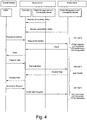
- FIG. 4 An example illustration of information exchange between components for radio management and seamless networking in the virtual processing environment is given in Fig. 4 . This shows the essence of interactions, and also shows where the different parts can be mapped on to a PPPoE based realisation described in the common digital interface section.
- waveform processing is normally carried out on a processing platform local to the relevant transceiver, the virtual processing environment also allows this to be distributed if required. In addition to giving access to additional processing resources, this also gives flexibility to equipment suppliers in the amount of waveform specific functionality that is provided with radio units. For, example, a radio unit might be supplied with physical layer functionality only (modulation, demodulation and channel coding), leaving protocol stack functionality to be implemented elsewhere.
- FIG. 5 An example illustration of the deployment of software/firmware components for waveform processing in the virtual processing environment is given in Fig. 5 , showing how processing for a given waveform can be distributed across radio units.
- FIG. 6 An example illustration of information exchange between components waveform processing in the virtual processing environment is given in Fig. 6 .
- the illustration shows how the physical layer and protocol stack can be located in separate radio units.
- a certifiable RTOS with time and memory space partitioning is used to keep the different processing applications separate. This, in conjunction with well-defined interfaces, eases certification.
- the virtual processing environment provides an optimised architecture for the next generation of communications avionics. It offers a high degree of flexibility, scalability, lower development cost and lower equipment cost.
- the common processing platform includes, for example, a common hardware platform, common interfaces, a common development environment and a common software execution environment.
- One of the common interfaces would be Ethernet for AFDX connectivity.
- a common interface to transceiver modules is also desirable, for example PCI Express or SRIO, Serial RapidIO.
- PCI Express is a high speed interconnect technology, employing serial links. It is based on point to point links, but the architecture includes switches which allow links to be routed in a tree structure, and also fanned out to multiple receivers from a single transmitter PCI Express is typically employed for chip to chip and board to board connections.
- the external cable specification also allows it to be employed in chassis to chassis connections.
- Serial RapidIO is another high speed interconnect technology, also employing serial links. It is based on point to point links, but the architecture includes switches which allow links to be routed in a flexible manner. Serial RapidIO is typically employed for chip to chip and board to board connections.
- a common platform does not preclude the evolution of that platform over time.
- version 1.0 might be deployed for a VHF radio and version 1.1 for an L-Band radio as well as an HF radio.
- the common platform can also come in multiple flavours supporting increasing processing capability. For example, one platform might only employ a processor, whereas another platform might employ a processor and an FPGA.
- External wireless aircraft communications employ a variety of communication means including HF, VHF and Satcom.
- Different interface schemes are employed to access the various services, which may be based on digital or analogue methods.
- the internal aircraft communications infrastructure becomes more and more IP based, it is desirable to have a single method for accessing all wireless services, covering both modern IP based services and legacy analogue services.
- the virtual distributed processing architecture employs a digital network, such as AFDX, for radio unit interconnection and interfacing to client systems.
- ADFX is an example of a deterministic digital network.
- Such a network provides a Type 1 service with guaranteed latency and bandwidth. Providing the bandwidth of the digital network is higher than that offered by the radio services, the digital network can support both Type 1 and Type 2 radio services.
- AFDX networks currently use 10 Mbit / s and 100 Mbit / s Ethernet networks and so support rates much higher than most radio services, except for very high bandwidth radio services such as WiMAX and DVB, which are likely to use a significant proportion of the maximum AFDX bandwidth today.
- WiMAX and DVB very high bandwidth radio services
- AFDX speeds are likely to increase in the future, following the evolution of Ethernet speeds.
- Such a method is provided for satellite communications, using the Ethernet Interface defined in Attachment 5 of ARINC 781. This uses PPPoE to set up and clear down primary context connections across the satellite link. Once a primary context has been set up, secondary contexts can be set up using Telnet sessions.
- Each context can be one of the following types:
- the idea is to take the Ethernet interface of ARINC 781 (or a derivative) and combine it with a network such as AFDX to support all IMR radio services.
- the client system uses PPPoE over AFDX to set up a session with a Satcom radio unit, requesting a background class.
- the Satcom radio unit establishes a primary context with a background class across the satellite link. IP packets from the client are sent over the Satcom link.
- the client system uses PPPoE over AFDX to set up a session with a Satcom radio unit, requesting a streaming class.
- the Satcom radio unit establishes a primary context with the streaming class across the satellite link.
- the client system regularly sends uncompressed digitised voice to the Satcom radio unit. The latter compresses the voice and sends it over the Satcom link using the streaming class.
- the client system uses PPPoE over AFDX to set up a session with a VHF radio unit, requesting a streaming class. This prepares the radio unit for transmission.
- the client system regularly sends uncompressed digitised voice to the VHF radio unit, which is transmitted on the VHF link. The latter uses the voice information to modulate the analogue VHF signal. This scenario is illustrated in Fig. 7 .
- the client system uses PPPoE over AFDX to set up a session with a Satcom radio unit, requesting a background class.
- the Satcom radio unit establishes a primary context with a background class across the satellite link.
- the client system uses Telnet to set up a secondary context with a streaming class.
- the client system regularly sends uncompressed digitised voice to the Satcom radio unit. The latter compresses the voice and sends it over the Satcom link using the streaming class.
- the client system uses PPPoE over AFDX to set up a session with a VHF radio unit, requesting a background class.
- the client system uses Telnet to 'set up' a secondary context with a streaming class. This prepares the radio for transmission.
- the client system regularly sends uncompressed digitised voice to the VHF radio unit, which is transmitted on the VHF link.
- the radio unit uses the voice information to modulate the analogue VHF signal. This scenario is illustrated in Fig. 7 .
- Fig. 8 An illustration of the information exchange to access VHF analogue services using PPPoE is given in Fig. 8 .
- the client could be located in the aircraft domain, or could be the Controller for seamless networking in a radio unit.
- HMI equipment in the cockpit can set up voice calls in the same way, regardless of whether voice will be carried over an analogue VHF system or a Satcom VOIP system.
- the common digital interface is achieved by combining the use of PPPoE and Telnet services with a network such as AFDX. This allows the interface to support
- controlling entity that carries out radio management functions, and a controlling entity that supports seamless networking. If desired, a single controlling entity can carry out both functions.
- Seamless networking is the concept of transferring information over different communication links without the information source or destination needing to select the communication link that should be used. For example, a short message might be sent over a VHF data link when the aircraft is within VHF range, or may be sent over a Satcom link when the aircraft is out of VHF range - the desired link is selected automatically .
- a single entity termed a Controller supports both radio management and seamless networking functions.
- Controller Priority Services 1 3 HF, VHF 2 2 HF, VHF 3 7 HF, VHF, Satcom 4 1 HF, VHF, Satcom
- All the Controllers are connected to each other via a network (e.g. Ethernet based AFDX).
- a network e.g. Ethernet based AFDX.
- Each Controller periodically broadcasts information about the status of the services it can provide and its priority number. Such broadcasts might be on Ethernet packets or IP packets.
- a Controller also broadcasts the same information for each of the other Controllers it can hear, thus providing information on its overall connectivity.
- Each Controller computes a metric that indicates the level of overall connectivity of each Controller, using a suitable algorithm.
- Such an algorithm can weight each service in an appropriate manner (for example, VHF services will currently be more important than HF or Satcom services).
- the Controllers broadcast this information to client systems on a regular basis.
- the client systems rank Controllers in order of the highest metric. If more than one Controller shares the same metric, then the priority level at commissioning is used to differentiate the ranking.
- the client systems can then select a Controller to use, based on ranking. For example, the pilot's HMI system could select the top-ranking Controller, whereas the co-pilot's HMI system could select the second ranking Controller. This scheme provides full redundancy.
- the invention may be implemented through hardware, firmware and software. It preferably employs Software Defined Radio techniques.
- each radio has a discrete module consisting of a transceiver and a processor platform, and preferably the processor platforms have a common architecture, which may be their hardware architecture and/or their interfaces and/or their development environment and/or their software execution environment.
- the processor platforms may alternatively be shared by two or more radio transceivers, i.e. they may be dedicated to plural transceivers.
- the hardware may be organised differently, so that for example the dedicated processor platforms are grouped in a module, for example a collection of processing cards, separate from the transceivers.
Landscapes
- Engineering & Computer Science (AREA)
- Aviation & Aerospace Engineering (AREA)
- Computer Networks & Wireless Communication (AREA)
- Signal Processing (AREA)
- Physics & Mathematics (AREA)
- Astronomy & Astrophysics (AREA)
- General Physics & Mathematics (AREA)
- Mobile Radio Communication Systems (AREA)
- Small-Scale Networks (AREA)
- Radio Relay Systems (AREA)
Claims (18)
- Flugzeugfunksystem, das mehrere Funkgeräte umfasst, wobei jedes Funkgerät einen Transceiver und eine dedizierte Prozessorplattform zum Durchführen von digitaler Signalverarbeitung für diesen Transceiver aufweist, wobei die Prozessoren jeder Plattform durch ein digitales Kommunikationsnetz miteinander verbunden sind, so dass die dedizierten Prozessorplattformen eine virtuelle Verarbeitungsumgebung bilden, in der die Verarbeitung von für das gesamte System relevanten Aufgaben über die Prozessoren verteilt ist.
- System nach Anspruch 1, wobei wenigstens eine der dedizierten Prozessorplattformen für zwei oder mehr der Transceiver dediziert ist.
- System nach Anspruch 1 oder Anspruch 2, wobei zwei oder mehr der dedizierten Prozessorplattformen in einem Modul separat von den Transceivern gruppiert sind.
- System nach einem der vorherigen Ansprüche, wobei das Netzwerk ein deterministisches AFDX-(Avionics Full Duplex Ethernet)-Netzwerk oder ein anderes deterministisches Netzwerk ist.
- System nach einem der Ansprüche 1 bis 3, wobei das Netzwerk ein Ethernet-Netzwerk ist.
- System nach einem vorherigen Anspruch, wobei die virtuelle Verarbeitungsumgebung CORBA, Common Objekt Request Broker Architecture, oder Echtzeit-CORBA entspricht.
- System nach einem der vorherigen Ansprüche, wobei wenigstens eines der Funkgeräte SDR-(Software Defined Radio)-Techniken einsetzt.
- System nach einem der vorherigen Ansprüche, wobei das System so konfiguriert ist, dass es bewirkt, dass zwei oder mehr der dedizierten Prozessorplattformen eine virtuelle Verarbeitungsumgebung für eine nahtlose Vernetzung über mehrere mögliche Funkkanäle bilden.
- System nach einem der vorherigen Ansprüche, wobei das System so konfiguriert ist, dass es bewirkt, dass zwei oder mehr der dedizierten Prozessorplattformen eine virtuelle Verarbeitungsumgebung für Funkmanagement bilden.
- System nach einem der vorherigen Ansprüche, wobei das System so konfiguriert ist, dass es bewirkt, dass zwei oder mehr der dedizierten Prozessorplattformen eine virtuelle Verarbeitungsumgebung für Wellenformverarbeitung bilden.
- System nach einem der vorherigen Ansprüche, wobei die dedizierten Prozessorplattformen eine gemeinsame Architektur haben, einschließlich einem oder mehreren aus einer gemeinsamen Hardware-Architektur; gemeinsamen Schnittstellen; einer gemeinsamen Entwicklungsumgebung; und einer gemeinsamen Software-Ausführungsumgebung.
- System nach einem der vorherigen Ansprüche, wobei jedes Funkgerät ein Transceiver-Modul umfasst, das über eine den Funkgeräten gemeinsame Schnittstelle mit der dedizierten Prozessorplattform verbunden ist.
- Flugzeugfunksystem nach einem der vorherigen Ansprüche, das einen Server umfasst, der zum Unterstützen von Kommunikationen über das Netzwerk mit PPPoE, Point to Point Protocol over Ethernet, konfiguriert ist, um eine gemeinsame digitale Schnittstelle zwischen einer Flugzeugdomäne und den Funkgeräten für mehrere Kommunikationstypen bereitzustellen.
- System nach Anspruch 13 und ferner gemäß einem der Ansprüche 1 bis 12.
- System nach einem der vorherigen Ansprüche, das wenigstens einen Controller umfasst, der mit dem Netzwerk verbunden ist, wobei jeder Controller zum Ermitteln seiner eigenen Gesamtkonnektivität und zum Rundsenden derselben über das Netzwerk konfiguriert ist, um zuzulassen, dass Client-Systeme einen Controller zur Verwendung auf der Basis der Rangordnung von Konnektivitäten auswählen.
- System nach Anspruch 15, wobei jeder Controller zum Ermitteln seiner Konnektivität auf der Basis des Funkdiensttyps, den er anbieten kann, und einer Prioritätsstufe konfiguriert ist, die aufgestellt und gespeichert wird, wenn das Flugzeugfunksystem in Betrieb genommen oder konfiguriert wird.
- System nach einem der vorherigen Ansprüche, das mehrere Antennensysteme umfasst, die jeweils mit einem jeweiligen Funkgerät durch eine RF-Kabelverbindung verbunden sind.
- Luftfahrtsystem, das Kabinen- und Cockpit-Mensch-Maschinen-Schnittstellen, Luftfahrtschnittstellen und wenigstens ein Flugzeugfunksystem nach einem der vorherigen Ansprüche umfasst, die alle durch das digitale Kommunikationsnetz miteinander verbunden sind.
Applications Claiming Priority (2)
| Application Number | Priority Date | Filing Date | Title |
|---|---|---|---|
| GB1002889A GB2477960A (en) | 2010-02-19 | 2010-02-19 | Integrated aircraft radio system in which a plurality of radios are networked together |
| PCT/GB2011/000111 WO2011101611A1 (en) | 2010-02-19 | 2011-01-27 | Aircraft radio system |
Publications (2)
| Publication Number | Publication Date |
|---|---|
| EP2536629A1 EP2536629A1 (de) | 2012-12-26 |
| EP2536629B1 true EP2536629B1 (de) | 2016-06-22 |
Family
ID=42114113
Family Applications (1)
| Application Number | Title | Priority Date | Filing Date |
|---|---|---|---|
| EP11703241.7A Active EP2536629B1 (de) | 2010-02-19 | 2011-01-27 | Flugzeugfunksystem |
Country Status (10)
| Country | Link |
|---|---|
| US (1) | US9169018B2 (de) |
| EP (1) | EP2536629B1 (de) |
| JP (2) | JP2013519589A (de) |
| CN (1) | CN102834319B (de) |
| BR (1) | BR112012021713B1 (de) |
| CA (1) | CA2790251C (de) |
| GB (1) | GB2477960A (de) |
| RU (1) | RU2564434C2 (de) |
| UA (1) | UA109649C2 (de) |
| WO (1) | WO2011101611A1 (de) |
Families Citing this family (11)
| Publication number | Priority date | Publication date | Assignee | Title |
|---|---|---|---|---|
| US9520903B2 (en) | 2014-05-20 | 2016-12-13 | Honeywell International Inc. | Interconnection fabric with protocol agnostic switch for flexible radio avionics |
| US10536232B2 (en) * | 2015-06-29 | 2020-01-14 | Visteon Global Technologies, Inc. | Integrating audio content with additional digital content |
| KR101948560B1 (ko) * | 2016-03-02 | 2019-02-15 | 한국전자통신연구원 | 항공 전자 시스템 및 그 구동 방법 |
| KR102033330B1 (ko) * | 2016-03-07 | 2019-10-17 | 한국전자통신연구원 | 항공전자 통신 모듈 및 이의 동작 방법 |
| CN106603143B (zh) * | 2016-11-29 | 2020-03-17 | 航天恒星科技有限公司 | 空间站试验平台及其控制器 |
| SE1750614A1 (en) | 2017-05-17 | 2018-11-18 | Icomera Ab | Communication system for aircrafts |
| US20190154825A1 (en) * | 2017-11-20 | 2019-05-23 | Honeywell International Inc. | Virtualized navigation and communication radios |
| CN109194497B (zh) * | 2018-07-17 | 2021-07-16 | 中国航空无线电电子研究所 | 面向软件无线电系统的双srio网络备份系统 |
| KR20210105930A (ko) * | 2018-12-25 | 2021-08-27 | 아이디아 가부시키가이샤 | 선박 동정 공유 항행 지원 시스템 |
| RU197960U1 (ru) * | 2020-01-24 | 2020-06-09 | Федеральное государственное унитарное предприятие «Государственный научно-исследовательский институт авиационных систем» ("ФГУП ГосНИИАС") | Оконечное устройство бортовой сети реального времени |
| CN111970288B (zh) * | 2020-08-24 | 2023-04-07 | 成都天奥信息科技有限公司 | 一种基于VoIP地空语音通信的发射跟随方法 |
Family Cites Families (32)
| Publication number | Priority date | Publication date | Assignee | Title |
|---|---|---|---|---|
| US7113780B2 (en) * | 1992-03-06 | 2006-09-26 | Aircell, Inc. | System for integrating an airborne wireless cellular network with terrestrial wireless cellular networks and the public switched telephone network |
| US7107062B2 (en) * | 1992-03-06 | 2006-09-12 | Aircell, Inc. | System for managing call handoffs between an aircraft and multiple cell sites |
| US7062268B2 (en) * | 1992-03-06 | 2006-06-13 | Aircell, Inc. | Overlapping spectrum cellular communication networks |
| US8081968B2 (en) * | 2000-10-11 | 2011-12-20 | Gogo Llc | System for creating an air-to-ground IP tunnel in an airborne wireless cellular network to differentiate individual passengers |
| US5940754A (en) * | 1992-06-17 | 1999-08-17 | Gte Laboratories Incorporated | Method of fault identification for multiplexed devices |
| US5608722A (en) * | 1995-04-03 | 1997-03-04 | Qualcomm Incorporated | Multi-user communication system architecture with distributed receivers |
| US6047165A (en) * | 1995-11-14 | 2000-04-04 | Harris Corporation | Wireless, frequency-agile spread spectrum ground link-based aircraft data communication system |
| US6018644A (en) * | 1997-01-28 | 2000-01-25 | Northrop Grumman Corporation | Low-loss, fault-tolerant antenna interface unit |
| US6671589B2 (en) * | 2001-02-13 | 2003-12-30 | William Holst | Method and apparatus to support remote and automatically initiated data loading and data acquisition of airborne computers using a wireless spread spectrum aircraft data services link |
| US20020160773A1 (en) * | 2001-03-29 | 2002-10-31 | Tenzing Communications, Inc. | Communications systems for aircraft including wireless systems |
| US6990338B2 (en) * | 2001-06-11 | 2006-01-24 | The Boeing Company | Mobile wireless local area network and related methods |
| US7054322B2 (en) * | 2001-08-31 | 2006-05-30 | The Boeing Company | Mobile communications network using point-to-point protocol over ethernet |
| JP2003218731A (ja) * | 2002-01-21 | 2003-07-31 | Nagano Japan Radio Co | ソフトウェア無線機用信号処理装置および無線システム |
| DE10211179C1 (de) * | 2002-03-14 | 2003-12-18 | Framatome Anp Gmbh | Abstandhalter für das Brennelement eines Siedewasserreaktors |
| ZA200507571B (en) * | 2003-03-21 | 2007-03-28 | Axesstel Inc | Wireless gateway |
| JP4453575B2 (ja) | 2004-09-07 | 2010-04-21 | 株式会社日立製作所 | ソフトウェア無線装置 |
| US7941248B1 (en) * | 2005-08-03 | 2011-05-10 | Rockwell Collins, Inc. | Method and apparatus for implementing and managing avionics functions |
| US7620127B1 (en) | 2005-09-28 | 2009-11-17 | Rockwell Collins, Inc. | High availability digital radio architecture |
| WO2008029053A2 (fr) * | 2006-09-06 | 2008-03-13 | Thomson Licensing | Reseau maille sans fils pour la distribution de contenu |
| US7158072B1 (en) * | 2006-09-08 | 2007-01-02 | Rockwell Collins, Inc. | Ethernet connection of airborne radar over fiber optic cable |
| US7847730B2 (en) * | 2006-09-27 | 2010-12-07 | Bae Systems Information And Electronic Systems Integration, Inc. | Software defined navigation signal generator |
| US8504019B2 (en) * | 2007-03-30 | 2013-08-06 | Livetv, Llc | Aircraft communications system with data memory cache and associated methods |
| FR2914450B1 (fr) * | 2007-03-30 | 2009-07-10 | Airbus Sas | Systeme de communication d'aeronef comprenant un terminal d'aeronef et une ressource portable |
| FR2914802B1 (fr) * | 2007-04-06 | 2011-02-18 | Airbus France | Procede et dispositif de gestion de canaux de communication pour des echanges de donnees a partir d'un aeronef |
| DE102007020480B4 (de) * | 2007-04-27 | 2009-04-09 | Airbus Deutschland Gmbh | Verfahren zum Überprüfen einer Kommunikationsverbindung |
| US8081933B2 (en) * | 2007-07-13 | 2011-12-20 | Honeywell International Inc. | Reconfigurable aircraft radio communications system |
| US8948960B2 (en) * | 2007-11-30 | 2015-02-03 | Honeywell International Inc. | Systems and methods for arbitrating sensor and actuator signals in a multi-channel control system |
| US8203483B2 (en) * | 2008-03-13 | 2012-06-19 | Cubic Corporation | Digital beamforming antenna and datalink array |
| JP2009223732A (ja) * | 2008-03-18 | 2009-10-01 | Hitachi Kokusai Electric Inc | 分散処理プログラム |
| US8019338B2 (en) * | 2008-05-29 | 2011-09-13 | Honeywell International Inc. | Reconfigurable aircraft communications system with integrated avionics communication router and audio management functions |
| US8559391B2 (en) * | 2010-02-12 | 2013-10-15 | Wei Lu | Open wireless architecture (OWA) unified airborne and terrestrial communications architecture |
| US9397745B2 (en) * | 2010-05-18 | 2016-07-19 | Qualcomm Incorporated | Hybrid satellite and mesh network system for aircraft and ship internet service |
-
2010
- 2010-02-19 GB GB1002889A patent/GB2477960A/en not_active Withdrawn
-
2011
- 2011-01-27 EP EP11703241.7A patent/EP2536629B1/de active Active
- 2011-01-27 CA CA2790251A patent/CA2790251C/en active Active
- 2011-01-27 JP JP2012553382A patent/JP2013519589A/ja active Pending
- 2011-01-27 BR BR112012021713-5A patent/BR112012021713B1/pt active IP Right Grant
- 2011-01-27 RU RU2012140017/11A patent/RU2564434C2/ru active
- 2011-01-27 US US13/579,915 patent/US9169018B2/en active Active
- 2011-01-27 UA UAA201210920A patent/UA109649C2/ru unknown
- 2011-01-27 WO PCT/GB2011/000111 patent/WO2011101611A1/en not_active Ceased
- 2011-01-27 CN CN201180010270.5A patent/CN102834319B/zh not_active Expired - Fee Related
-
2016
- 2016-01-28 JP JP2016014800A patent/JP6255043B2/ja active Active
Non-Patent Citations (1)
| Title |
|---|
| None * |
Also Published As
| Publication number | Publication date |
|---|---|
| BR112012021713B1 (pt) | 2022-01-11 |
| CA2790251A1 (en) | 2011-08-25 |
| BR112012021713A2 (pt) | 2016-08-23 |
| WO2011101611A8 (en) | 2012-09-27 |
| US20130190948A1 (en) | 2013-07-25 |
| JP2013519589A (ja) | 2013-05-30 |
| CA2790251C (en) | 2018-02-20 |
| US9169018B2 (en) | 2015-10-27 |
| RU2564434C2 (ru) | 2015-09-27 |
| JP6255043B2 (ja) | 2017-12-27 |
| UA109649C2 (en) | 2015-09-25 |
| RU2012140017A (ru) | 2014-03-27 |
| JP2016146627A (ja) | 2016-08-12 |
| GB2477960A (en) | 2011-08-24 |
| EP2536629A1 (de) | 2012-12-26 |
| CN102834319B (zh) | 2016-09-07 |
| WO2011101611A1 (en) | 2011-08-25 |
| GB201002889D0 (en) | 2010-04-07 |
| CN102834319A (zh) | 2012-12-19 |
Similar Documents
| Publication | Publication Date | Title |
|---|---|---|
| US9169018B2 (en) | Aircraft radio system | |
| US8774795B2 (en) | Reconfigurable satcom avionics radio | |
| JP7241484B2 (ja) | ネットワーク情報に基づいてビークル搭載のスイッチマトリクスの構成を行うためのシステム及び方法 | |
| EP2933931B1 (de) | Verwaltungsanordnung für Funkmittel für Flugzeug mit software bestimmte Funkeinheit. | |
| EP4597879A2 (de) | Breitband-satellitenendgerät | |
| KR20110108362A (ko) | 분산 안테나 시스템에서 개선된 디지털 rf 전송을 위한 시스템과 방법 | |
| US11070285B2 (en) | System and method for configuring a multistage interconnection network based on user traffic demand | |
| US20050259668A1 (en) | Method of providing broadband services in client dense environments | |
| US12027054B2 (en) | Communication system and method of controlling air traffic of an airspace | |
| US20040087283A1 (en) | Slice based architecture for a multifunction radio | |
| JP2002152847A (ja) | 電子無線システム用送受信機―プロセッサ構築ブロック | |
| JP2022552941A (ja) | 分散アンテナシステムのマスタユニットのためのパッシブバックプレーンアーキテクチャ | |
| CN106603143B (zh) | 空间站试验平台及其控制器 | |
| US9197906B1 (en) | Aircraft cabin management system | |
| US9520903B2 (en) | Interconnection fabric with protocol agnostic switch for flexible radio avionics | |
| MX2007008248A (es) | Un metodo y sistema para compensar una falla de pasarela de satelite. | |
| US20020007234A1 (en) | Apparatus and method for transitioning from a dual air/ground and ground/ground aeronautical data network architecture to an end-to-end aeronautical data network architecture | |
| KR102226254B1 (ko) | 분산 안테나 시스템 및 분산 안테나 시스템의 서비스 방법 | |
| US7643440B1 (en) | Integrated television and broadband data system for aircraft | |
| Jongeling et al. | A common platform for dsn receiver development | |
| KR101708563B1 (ko) | Utp 케이블을 이용한 신호 분산 장치 및 신호 분산 방법 | |
| Wang et al. | Research of flexible terminal | |
| US20060059523A1 (en) | Receiving and bridging broadband access signals for wired and wireless redistribution | |
| Baddoo et al. | ICST Transactions | |
| Baddoo et al. | The SANDRA Communications Concept–Integration of Radios |
Legal Events
| Date | Code | Title | Description |
|---|---|---|---|
| PUAI | Public reference made under article 153(3) epc to a published international application that has entered the european phase |
Free format text: ORIGINAL CODE: 0009012 |
|
| 17P | Request for examination filed |
Effective date: 20120815 |
|
| AK | Designated contracting states |
Kind code of ref document: A1 Designated state(s): AL AT BE BG CH CY CZ DE DK EE ES FI FR GB GR HR HU IE IS IT LI LT LU LV MC MK MT NL NO PL PT RO RS SE SI SK SM TR |
|
| DAX | Request for extension of the european patent (deleted) | ||
| GRAP | Despatch of communication of intention to grant a patent |
Free format text: ORIGINAL CODE: EPIDOSNIGR1 |
|
| INTG | Intention to grant announced |
Effective date: 20151223 |
|
| GRAR | Information related to intention to grant a patent recorded |
Free format text: ORIGINAL CODE: EPIDOSNIGR71 |
|
| GRAS | Grant fee paid |
Free format text: ORIGINAL CODE: EPIDOSNIGR3 |
|
| GRAA | (expected) grant |
Free format text: ORIGINAL CODE: 0009210 |
|
| INTG | Intention to grant announced |
Effective date: 20160512 |
|
| AK | Designated contracting states |
Kind code of ref document: B1 Designated state(s): AL AT BE BG CH CY CZ DE DK EE ES FI FR GB GR HR HU IE IS IT LI LT LU LV MC MK MT NL NO PL PT RO RS SE SI SK SM TR |
|
| REG | Reference to a national code |
Ref country code: GB Ref legal event code: FG4D |
|
| REG | Reference to a national code |
Ref country code: CH Ref legal event code: EP |
|
| REG | Reference to a national code |
Ref country code: IE Ref legal event code: FG4D |
|
| REG | Reference to a national code |
Ref country code: AT Ref legal event code: REF Ref document number: 807506 Country of ref document: AT Kind code of ref document: T Effective date: 20160715 |
|
| REG | Reference to a national code |
Ref country code: DE Ref legal event code: R096 Ref document number: 602011027544 Country of ref document: DE |
|
| REG | Reference to a national code |
Ref country code: LT Ref legal event code: MG4D |
|
| REG | Reference to a national code |
Ref country code: NL Ref legal event code: MP Effective date: 20160622 |
|
| PG25 | Lapsed in a contracting state [announced via postgrant information from national office to epo] |
Ref country code: NO Free format text: LAPSE BECAUSE OF FAILURE TO SUBMIT A TRANSLATION OF THE DESCRIPTION OR TO PAY THE FEE WITHIN THE PRESCRIBED TIME-LIMIT Effective date: 20160922 Ref country code: LT Free format text: LAPSE BECAUSE OF FAILURE TO SUBMIT A TRANSLATION OF THE DESCRIPTION OR TO PAY THE FEE WITHIN THE PRESCRIBED TIME-LIMIT Effective date: 20160622 Ref country code: FI Free format text: LAPSE BECAUSE OF FAILURE TO SUBMIT A TRANSLATION OF THE DESCRIPTION OR TO PAY THE FEE WITHIN THE PRESCRIBED TIME-LIMIT Effective date: 20160622 |
|
| REG | Reference to a national code |
Ref country code: AT Ref legal event code: MK05 Ref document number: 807506 Country of ref document: AT Kind code of ref document: T Effective date: 20160622 |
|
| PG25 | Lapsed in a contracting state [announced via postgrant information from national office to epo] |
Ref country code: GR Free format text: LAPSE BECAUSE OF FAILURE TO SUBMIT A TRANSLATION OF THE DESCRIPTION OR TO PAY THE FEE WITHIN THE PRESCRIBED TIME-LIMIT Effective date: 20160923 Ref country code: NL Free format text: LAPSE BECAUSE OF FAILURE TO SUBMIT A TRANSLATION OF THE DESCRIPTION OR TO PAY THE FEE WITHIN THE PRESCRIBED TIME-LIMIT Effective date: 20160622 Ref country code: RS Free format text: LAPSE BECAUSE OF FAILURE TO SUBMIT A TRANSLATION OF THE DESCRIPTION OR TO PAY THE FEE WITHIN THE PRESCRIBED TIME-LIMIT Effective date: 20160622 Ref country code: HR Free format text: LAPSE BECAUSE OF FAILURE TO SUBMIT A TRANSLATION OF THE DESCRIPTION OR TO PAY THE FEE WITHIN THE PRESCRIBED TIME-LIMIT Effective date: 20160622 Ref country code: SE Free format text: LAPSE BECAUSE OF FAILURE TO SUBMIT A TRANSLATION OF THE DESCRIPTION OR TO PAY THE FEE WITHIN THE PRESCRIBED TIME-LIMIT Effective date: 20160622 Ref country code: LV Free format text: LAPSE BECAUSE OF FAILURE TO SUBMIT A TRANSLATION OF THE DESCRIPTION OR TO PAY THE FEE WITHIN THE PRESCRIBED TIME-LIMIT Effective date: 20160622 |
|
| REG | Reference to a national code |
Ref country code: FR Ref legal event code: PLFP Year of fee payment: 7 |
|
| PG25 | Lapsed in a contracting state [announced via postgrant information from national office to epo] |
Ref country code: SK Free format text: LAPSE BECAUSE OF FAILURE TO SUBMIT A TRANSLATION OF THE DESCRIPTION OR TO PAY THE FEE WITHIN THE PRESCRIBED TIME-LIMIT Effective date: 20160622 Ref country code: RO Free format text: LAPSE BECAUSE OF FAILURE TO SUBMIT A TRANSLATION OF THE DESCRIPTION OR TO PAY THE FEE WITHIN THE PRESCRIBED TIME-LIMIT Effective date: 20160622 Ref country code: EE Free format text: LAPSE BECAUSE OF FAILURE TO SUBMIT A TRANSLATION OF THE DESCRIPTION OR TO PAY THE FEE WITHIN THE PRESCRIBED TIME-LIMIT Effective date: 20160622 Ref country code: IS Free format text: LAPSE BECAUSE OF FAILURE TO SUBMIT A TRANSLATION OF THE DESCRIPTION OR TO PAY THE FEE WITHIN THE PRESCRIBED TIME-LIMIT Effective date: 20161022 |
|
| PG25 | Lapsed in a contracting state [announced via postgrant information from national office to epo] |
Ref country code: SM Free format text: LAPSE BECAUSE OF FAILURE TO SUBMIT A TRANSLATION OF THE DESCRIPTION OR TO PAY THE FEE WITHIN THE PRESCRIBED TIME-LIMIT Effective date: 20160622 Ref country code: AT Free format text: LAPSE BECAUSE OF FAILURE TO SUBMIT A TRANSLATION OF THE DESCRIPTION OR TO PAY THE FEE WITHIN THE PRESCRIBED TIME-LIMIT Effective date: 20160622 Ref country code: BE Free format text: LAPSE BECAUSE OF FAILURE TO SUBMIT A TRANSLATION OF THE DESCRIPTION OR TO PAY THE FEE WITHIN THE PRESCRIBED TIME-LIMIT Effective date: 20160622 Ref country code: PL Free format text: LAPSE BECAUSE OF FAILURE TO SUBMIT A TRANSLATION OF THE DESCRIPTION OR TO PAY THE FEE WITHIN THE PRESCRIBED TIME-LIMIT Effective date: 20160622 Ref country code: ES Free format text: LAPSE BECAUSE OF FAILURE TO SUBMIT A TRANSLATION OF THE DESCRIPTION OR TO PAY THE FEE WITHIN THE PRESCRIBED TIME-LIMIT Effective date: 20160622 Ref country code: PT Free format text: LAPSE BECAUSE OF FAILURE TO SUBMIT A TRANSLATION OF THE DESCRIPTION OR TO PAY THE FEE WITHIN THE PRESCRIBED TIME-LIMIT Effective date: 20161024 |
|
| REG | Reference to a national code |
Ref country code: DE Ref legal event code: R097 Ref document number: 602011027544 Country of ref document: DE |
|
| PLBE | No opposition filed within time limit |
Free format text: ORIGINAL CODE: 0009261 |
|
| STAA | Information on the status of an ep patent application or granted ep patent |
Free format text: STATUS: NO OPPOSITION FILED WITHIN TIME LIMIT |
|
| 26N | No opposition filed |
Effective date: 20170323 |
|
| PG25 | Lapsed in a contracting state [announced via postgrant information from national office to epo] |
Ref country code: DK Free format text: LAPSE BECAUSE OF FAILURE TO SUBMIT A TRANSLATION OF THE DESCRIPTION OR TO PAY THE FEE WITHIN THE PRESCRIBED TIME-LIMIT Effective date: 20160622 |
|
| PG25 | Lapsed in a contracting state [announced via postgrant information from national office to epo] |
Ref country code: SI Free format text: LAPSE BECAUSE OF FAILURE TO SUBMIT A TRANSLATION OF THE DESCRIPTION OR TO PAY THE FEE WITHIN THE PRESCRIBED TIME-LIMIT Effective date: 20160622 |
|
| REG | Reference to a national code |
Ref country code: CH Ref legal event code: PL |
|
| PG25 | Lapsed in a contracting state [announced via postgrant information from national office to epo] |
Ref country code: MC Free format text: LAPSE BECAUSE OF FAILURE TO SUBMIT A TRANSLATION OF THE DESCRIPTION OR TO PAY THE FEE WITHIN THE PRESCRIBED TIME-LIMIT Effective date: 20160622 |
|
| PG25 | Lapsed in a contracting state [announced via postgrant information from national office to epo] |
Ref country code: CH Free format text: LAPSE BECAUSE OF NON-PAYMENT OF DUE FEES Effective date: 20170131 Ref country code: LI Free format text: LAPSE BECAUSE OF NON-PAYMENT OF DUE FEES Effective date: 20170131 |
|
| REG | Reference to a national code |
Ref country code: IE Ref legal event code: MM4A |
|
| PG25 | Lapsed in a contracting state [announced via postgrant information from national office to epo] |
Ref country code: LU Free format text: LAPSE BECAUSE OF NON-PAYMENT OF DUE FEES Effective date: 20170127 |
|
| REG | Reference to a national code |
Ref country code: FR Ref legal event code: PLFP Year of fee payment: 8 |
|
| PG25 | Lapsed in a contracting state [announced via postgrant information from national office to epo] |
Ref country code: IE Free format text: LAPSE BECAUSE OF NON-PAYMENT OF DUE FEES Effective date: 20170127 |
|
| PG25 | Lapsed in a contracting state [announced via postgrant information from national office to epo] |
Ref country code: MT Free format text: LAPSE BECAUSE OF NON-PAYMENT OF DUE FEES Effective date: 20170127 |
|
| PG25 | Lapsed in a contracting state [announced via postgrant information from national office to epo] |
Ref country code: AL Free format text: LAPSE BECAUSE OF FAILURE TO SUBMIT A TRANSLATION OF THE DESCRIPTION OR TO PAY THE FEE WITHIN THE PRESCRIBED TIME-LIMIT Effective date: 20160622 |
|
| REG | Reference to a national code |
Ref country code: DE Ref legal event code: R082 Ref document number: 602011027544 Country of ref document: DE Representative=s name: MARKS & CLERK (LUXEMBOURG) LLP, LU Ref country code: DE Ref legal event code: R081 Ref document number: 602011027544 Country of ref document: DE Owner name: THALES HOLDINGS UK PLC, READING, GB Free format text: FORMER OWNER: THALES HOLDINGS UK PLC, ADDLESTONE, SURREY, GB |
|
| PG25 | Lapsed in a contracting state [announced via postgrant information from national office to epo] |
Ref country code: HU Free format text: LAPSE BECAUSE OF FAILURE TO SUBMIT A TRANSLATION OF THE DESCRIPTION OR TO PAY THE FEE WITHIN THE PRESCRIBED TIME-LIMIT; INVALID AB INITIO Effective date: 20110127 |
|
| PG25 | Lapsed in a contracting state [announced via postgrant information from national office to epo] |
Ref country code: BG Free format text: LAPSE BECAUSE OF FAILURE TO SUBMIT A TRANSLATION OF THE DESCRIPTION OR TO PAY THE FEE WITHIN THE PRESCRIBED TIME-LIMIT Effective date: 20160622 |
|
| PG25 | Lapsed in a contracting state [announced via postgrant information from national office to epo] |
Ref country code: CY Free format text: LAPSE BECAUSE OF NON-PAYMENT OF DUE FEES Effective date: 20160622 |
|
| PG25 | Lapsed in a contracting state [announced via postgrant information from national office to epo] |
Ref country code: MK Free format text: LAPSE BECAUSE OF FAILURE TO SUBMIT A TRANSLATION OF THE DESCRIPTION OR TO PAY THE FEE WITHIN THE PRESCRIBED TIME-LIMIT Effective date: 20160622 |
|
| PG25 | Lapsed in a contracting state [announced via postgrant information from national office to epo] |
Ref country code: TR Free format text: LAPSE BECAUSE OF FAILURE TO SUBMIT A TRANSLATION OF THE DESCRIPTION OR TO PAY THE FEE WITHIN THE PRESCRIBED TIME-LIMIT Effective date: 20160622 |
|
| PGFP | Annual fee paid to national office [announced via postgrant information from national office to epo] |
Ref country code: IT Payment date: 20201229 Year of fee payment: 11 Ref country code: CZ Payment date: 20210114 Year of fee payment: 11 |
|
| PG25 | Lapsed in a contracting state [announced via postgrant information from national office to epo] |
Ref country code: CZ Free format text: LAPSE BECAUSE OF NON-PAYMENT OF DUE FEES Effective date: 20220127 |
|
| PG25 | Lapsed in a contracting state [announced via postgrant information from national office to epo] |
Ref country code: IT Free format text: LAPSE BECAUSE OF NON-PAYMENT OF DUE FEES Effective date: 20220127 |
|
| P01 | Opt-out of the competence of the unified patent court (upc) registered |
Effective date: 20230511 |
|
| PGFP | Annual fee paid to national office [announced via postgrant information from national office to epo] |
Ref country code: GB Payment date: 20251218 Year of fee payment: 16 |
|
| PGFP | Annual fee paid to national office [announced via postgrant information from national office to epo] |
Ref country code: FR Payment date: 20251222 Year of fee payment: 16 |
|
| PGFP | Annual fee paid to national office [announced via postgrant information from national office to epo] |
Ref country code: DE Payment date: 20251224 Year of fee payment: 16 |