EP2535601A1 - Ankerschraube - Google Patents
Ankerschraube Download PDFInfo
- Publication number
- EP2535601A1 EP2535601A1 EP12169002A EP12169002A EP2535601A1 EP 2535601 A1 EP2535601 A1 EP 2535601A1 EP 12169002 A EP12169002 A EP 12169002A EP 12169002 A EP12169002 A EP 12169002A EP 2535601 A1 EP2535601 A1 EP 2535601A1
- Authority
- EP
- European Patent Office
- Prior art keywords
- fastening element
- self
- screw shaft
- drill head
- anchor bolt
- Prior art date
- Legal status (The legal status is an assumption and is not a legal conclusion. Google has not performed a legal analysis and makes no representation as to the accuracy of the status listed.)
- Withdrawn
Links
- 238000010079 rubber tapping Methods 0.000 claims abstract description 65
- 238000000034 method Methods 0.000 claims abstract description 12
- 239000000463 material Substances 0.000 claims description 47
- 238000005553 drilling Methods 0.000 claims description 36
- 239000011435 rock Substances 0.000 claims description 9
- 239000012530 fluid Substances 0.000 claims description 5
- 238000010348 incorporation Methods 0.000 claims description 3
- 238000005065 mining Methods 0.000 claims description 3
- 239000007787 solid Substances 0.000 claims description 3
- 230000005641 tunneling Effects 0.000 claims description 3
- 238000011010 flushing procedure Methods 0.000 description 3
- 238000009435 building construction Methods 0.000 description 2
- 229920002430 Fibre-reinforced plastic Polymers 0.000 description 1
- 229910000831 Steel Inorganic materials 0.000 description 1
- 238000004873 anchoring Methods 0.000 description 1
- 230000015572 biosynthetic process Effects 0.000 description 1
- 239000011083 cement mortar Substances 0.000 description 1
- 230000000694 effects Effects 0.000 description 1
- 238000000605 extraction Methods 0.000 description 1
- 239000011151 fibre-reinforced plastic Substances 0.000 description 1
- -1 for example Substances 0.000 description 1
- 238000002347 injection Methods 0.000 description 1
- 239000007924 injection Substances 0.000 description 1
- 239000007788 liquid Substances 0.000 description 1
- 239000002184 metal Substances 0.000 description 1
- 230000000284 resting effect Effects 0.000 description 1
- 239000010959 steel Substances 0.000 description 1
- 229920003002 synthetic resin Polymers 0.000 description 1
- 239000000057 synthetic resin Substances 0.000 description 1
Images
Classifications
-
- F—MECHANICAL ENGINEERING; LIGHTING; HEATING; WEAPONS; BLASTING
- F16—ENGINEERING ELEMENTS AND UNITS; GENERAL MEASURES FOR PRODUCING AND MAINTAINING EFFECTIVE FUNCTIONING OF MACHINES OR INSTALLATIONS; THERMAL INSULATION IN GENERAL
- F16B—DEVICES FOR FASTENING OR SECURING CONSTRUCTIONAL ELEMENTS OR MACHINE PARTS TOGETHER, e.g. NAILS, BOLTS, CIRCLIPS, CLAMPS, CLIPS OR WEDGES; JOINTS OR JOINTING
- F16B13/00—Dowels or other devices fastened in walls or the like by inserting them in holes made therein for that purpose
- F16B13/002—Dowels or other devices fastened in walls or the like by inserting them in holes made therein for that purpose self-cutting
-
- F—MECHANICAL ENGINEERING; LIGHTING; HEATING; WEAPONS; BLASTING
- F16—ENGINEERING ELEMENTS AND UNITS; GENERAL MEASURES FOR PRODUCING AND MAINTAINING EFFECTIVE FUNCTIONING OF MACHINES OR INSTALLATIONS; THERMAL INSULATION IN GENERAL
- F16B—DEVICES FOR FASTENING OR SECURING CONSTRUCTIONAL ELEMENTS OR MACHINE PARTS TOGETHER, e.g. NAILS, BOLTS, CIRCLIPS, CLAMPS, CLIPS OR WEDGES; JOINTS OR JOINTING
- F16B25/00—Screws that cut thread in the body into which they are screwed, e.g. wood screws
- F16B25/001—Screws that cut thread in the body into which they are screwed, e.g. wood screws characterised by the material of the body into which the screw is screwed
- F16B25/0026—Screws that cut thread in the body into which they are screwed, e.g. wood screws characterised by the material of the body into which the screw is screwed the material being a hard non-organic material, e.g. stone, concrete or drywall
-
- F—MECHANICAL ENGINEERING; LIGHTING; HEATING; WEAPONS; BLASTING
- F16—ENGINEERING ELEMENTS AND UNITS; GENERAL MEASURES FOR PRODUCING AND MAINTAINING EFFECTIVE FUNCTIONING OF MACHINES OR INSTALLATIONS; THERMAL INSULATION IN GENERAL
- F16B—DEVICES FOR FASTENING OR SECURING CONSTRUCTIONAL ELEMENTS OR MACHINE PARTS TOGETHER, e.g. NAILS, BOLTS, CIRCLIPS, CLAMPS, CLIPS OR WEDGES; JOINTS OR JOINTING
- F16B25/00—Screws that cut thread in the body into which they are screwed, e.g. wood screws
- F16B25/0036—Screws that cut thread in the body into which they are screwed, e.g. wood screws characterised by geometric details of the screw
- F16B25/0094—Screws that cut thread in the body into which they are screwed, e.g. wood screws characterised by geometric details of the screw the screw being assembled or manufactured from several components, e.g. a tip out of a first material welded to shaft of a second material
-
- F—MECHANICAL ENGINEERING; LIGHTING; HEATING; WEAPONS; BLASTING
- F16—ENGINEERING ELEMENTS AND UNITS; GENERAL MEASURES FOR PRODUCING AND MAINTAINING EFFECTIVE FUNCTIONING OF MACHINES OR INSTALLATIONS; THERMAL INSULATION IN GENERAL
- F16B—DEVICES FOR FASTENING OR SECURING CONSTRUCTIONAL ELEMENTS OR MACHINE PARTS TOGETHER, e.g. NAILS, BOLTS, CIRCLIPS, CLAMPS, CLIPS OR WEDGES; JOINTS OR JOINTING
- F16B25/00—Screws that cut thread in the body into which they are screwed, e.g. wood screws
- F16B25/10—Screws performing an additional function to thread-forming, e.g. drill screws or self-piercing screws
- F16B25/103—Screws performing an additional function to thread-forming, e.g. drill screws or self-piercing screws by means of a drilling screw-point, i.e. with a cutting and material removing action
-
- Y—GENERAL TAGGING OF NEW TECHNOLOGICAL DEVELOPMENTS; GENERAL TAGGING OF CROSS-SECTIONAL TECHNOLOGIES SPANNING OVER SEVERAL SECTIONS OF THE IPC; TECHNICAL SUBJECTS COVERED BY FORMER USPC CROSS-REFERENCE ART COLLECTIONS [XRACs] AND DIGESTS
- Y10—TECHNICAL SUBJECTS COVERED BY FORMER USPC
- Y10T—TECHNICAL SUBJECTS COVERED BY FORMER US CLASSIFICATION
- Y10T29/00—Metal working
- Y10T29/49—Method of mechanical manufacture
- Y10T29/49826—Assembling or joining
- Y10T29/49947—Assembling or joining by applying separate fastener
Definitions
- the present invention relates to an anchor bolt according to the preamble of claim 1 and a method for fastening an anchor bolt according to the preamble of claim 11.
- Anchor bolts are used for a wide variety of engineering applications to attach an object to the anchor bolt.
- the anchor bolt is screwed with a self-tapping thread into the hole, the diameter of the self-tapping thread is greater than the diameter of the bore, so that the self-tapping thread cuts into the material itself and produces a positive connection between the material and the self-tapping thread.
- two operations are required, namely first the incorporation of the bore with a drill and then the introduction of the anchor bolt.
- self-drilling anchor bolts which have a drill head on the screw shaft. These self-drilling anchor bolts can be used in one operation with the help of Drill head at a front end of the screw shaft incorporated a bore in the material and with the self-tapping thread on the screw shank a positive connection between the anchor bolt and the bore limiting material are made.
- the anchor bolt has a screw shaft and at the front end of the screw shaft, a drill head is arranged. Further, the screw shaft is provided with a self-tapping thread and the diameter of the screw shaft in the region of the self-tapping thread without the self-tapping thread substantially corresponds to the diameter of the drill head.
- the EP 1 760 331 A2 shows a fastener for hard surfaces, such as concrete masonry or the like, with a cylindrical base body, on the outside at least partially a self-tapping thread is provided and having a first end with a bottom portion and a second, the first end facing away from the base body internal engaging means for a setting tool and having a receptacle open to the second end, which is provided with a load application means, wherein the receptacle connects in the direction of the second end of the engagement means, wherein the engagement means is formed as a continuous opening in the bottom portion.
- the object of the present invention is to provide an anchor bolt and a method for fixing an anchor bolt available in which the anchor bolt can be inexpensively and reliably secured with a small technical effort.
- a self-drilling anchor bolt for use in mining, tunneling, civil engineering and for screwing into rock or a structure
- a screw shaft having a front end and a rear end, one at the front end the drill shank formed drill head, a self-tapping thread for fixing the anchor bolt in a bore incorporated with the drill
- the anchor bolt comprises a fastener as a separate component in addition to the screw shaft and the self-tapping thread is formed on the fastener.
- the self-tapping thread is thus decoupled from the screw shaft formed on a separate component.
- the fastening element is mounted axially displaceably on the screw shaft.
- the anchor screw can only be insufficiently secured in the material which delimits the bore with the self-tapping thread.
- the axial drilling motion depends on various circumstances, particularly on the upcoming rock.
- the axial movement of the screw shaft during drilling is different than the required axial movement due to the pitch of the self-tapping thread.
- the self-tapping thread may act to promote the material towards the borehole mouth, thus reducing the strength of the material in the area of the self-tapping thread and permitting a poorer bond between the tapping thread and the material.
- the fastener can be screwed or incorporated axially with the self-tapping thread according to the pitch of the self-tapping thread in the material.
- the fastening element in particular formed as a sleeve, formed with an opening, disposed within the opening of the screw shaft and the outside of the fastening element, the self-tapping thread is formed.
- a torque can be transmitted from the screw shaft to the fastening element, in particular by means of a positive connection between the fastening element at the opening and the screw shaft.
- the screw shank can thus be set in a rotational movement and this is transmitted to the fastening element, thereby screwing the fastening element into the bore.
- At least one sliding surface is expediently formed on the fastening element at the opening and on the screw shank, which each lie on top of one another, and effect an axial sliding bearing of the fastening element on the screw shaft, and preferably the at least one sliding surface additionally forms the positive connection for transmitting the torque ,
- the opening of the fastening element has at least one longitudinal groove and between the at least one longitudinal groove and the fastening element forms a gap for the passage of drilling material and / or a rinsing fluid.
- the longitudinal groove can thereby advantageously Drilling material or flushing fluid are promoted during drilling from the region of the drill head to the well mouth and / or flushing fluid from the well mouth to the drill head or vice versa.
- the outer diameter of the fastener without the self-tapping thread is equal to or smaller than the maximum diameter of the drill head.
- the outer diameter of the fastener without the self-tapping thread is less than 20, 10, 5, 3, 2 or 1% smaller than the maximum diameter of the drill head. The self-tapping thread thus cuts into the material not machined by the drill head.
- the screw shaft is provided on the outside with a profiling for conveying the drilling material when drilling from the drill head to a borehole mouth and preferably the profiling is helical, in particular partially helical, formed.
- the screw shaft is divided into a first portion in the region of the front end and a second portion in the region of the rear end and the screw shaft has at the first portion a small diameter than at the second portion, so that the fastening element at an axial arrangement on the first portion has no positive connection with the screw shaft.
- the fastening element at an axial arrangement on the first portion has no positive connection with the screw shaft.
- the screw shank can be unscrewed from the drill head, for example by means of a screw connection, and then another screw shank can be inserted and connected to the drill head, for example by means of the screw connection or a bayonet connection.
- the screw shaft is formed as a solid or a hollow cross-section and / or at the rear end of the screw shaft an anchor head is formed and / or the diameter of the fastener with the self-tapping thread is greater than the maximum diameter of the drill head, so that with the screwed Fastening element of the drill head and thus also connected to the drill head screw shank can be fastened axially in the bore.
- a polygon is preferably formed on the anchor head in order thereby to be able to apply a torque to the movement of the screw shaft by means of a drilling tool on the anchor head and thus also on the screw shaft.
- Method according to the invention for fastening an anchor bolt, in particular anchor bolt described in this patent application with the steps: incorporating a bore with a drill head formed on a screw shank, fastening the anchor bolt with a self-tapping thread of the anchor bolt in the bore, wherein the self-tapping thread during screwing in the bore limiting material performs an axial movement relative to the screw shaft toward a front end of the screw shaft.
- the thread when screwing in the self-tapping thread, the thread cuts into the material delimiting the bore, e.g. As rock or concrete, and / or a positive connection is made between the thread and the bore limiting material and / or the self-tapping thread is formed on a fastener as a separate component to the screw shaft and the fastener performs the axial movement relative to the screw shaft toward a front end of the screw shaft.
- the fastener when screwing in the self-tapping thread, the thread cuts into the material delimiting the bore, e.g. As rock or concrete, and / or a positive connection is made between the thread and the bore limiting material and / or the self-tapping thread is formed on a fastener as a separate component to the screw shaft and the fastener performs the axial movement relative to the screw shaft toward a front end of the screw shaft.
- the self-tapping thread is screwed into the bore-limiting material during drilling with the drill head, and preferably the fastener carries out the rotational movement of the screw shaft for drilling with the drill head due to a connection between the screw shaft and the fastener which produces a torque transfers from the screw shaft to the fastener.
- the self-tapping thread is screwed into the bore limiting material after, preferably, partially incorporating the bore with the drill head.
- the fastener is moved with the self-tapping thread axially to the drill head or at a distance of less than 10cm, 5cm or 2cm to the drill bit as it is screwed into the material delimiting the bore and / or the drill bit rests on the screwed fastener , so that the drill head and thus also the screw shaft is fastened axially with the fastening element in the bore.
- the screw shaft is drilled with the screw head manually or with drilling equipment in the material.
- the screw shaft is rotated with the screw head rotating or rotating or rotationally whirling and / or with a liquid or air or drilled with an extraction in the material.
- the fastener is axially disposed axially of the screw shaft in the region of the rear end of the screw shaft, so that at the beginning of the drilling process, the self-tapping thread on the fastener does not fit into the bore limiting material einschraubt.
- the fastener with the self-tapping thread cuts into the material limiting the bore, since the fastener at the beginning of the drilling process axially in the rear End of the screw shaft is arranged axially on the screw shaft and only then the fastener moves axially toward the front end of the screw shaft.
- the fastening element is plugged onto the screw shaft and screwed in manually or motor-driven only after a boring of the screw shaft with the drill head.
- a hardenable fixation material for.
- synthetic resin or cement mortar a space between the anchor bolt and the bore limiting material introduced.
- the carrying capacity of the anchor bolt can be further increased by an injection method.
- the hardenable fixing material is introduced by a longitudinal channel on the screw shaft in a configuration of the screw shaft as a hollow cross-section.
- the anchor bolt is at least partially, in particular completely, made of metal, for. As steel, or, preferably fiber reinforced plastic, for. B. GRP.
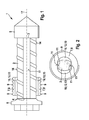
- self-drilling anchor bolt 1 is used to secure with the help of the anchor bolt 1 an object.
- the anchor bolt 1 is used, for example, in building construction to attach objects to concrete walls or ceilings or mining to attach in the upcoming rock in the tunnel also an object.
- the anchor bolt 1 has a screw shank 2 as a solid cross section with a front end 3 and a rear end 4. At the front end 3, a drill head 5 is fixed to the screw shaft 2 and at the rear end 4 of the screw shank 2 an anchor head 6 is attached.
- a trained as a sleeve 8 fastener 7 has an opening 10.
- the fastening element 7 is pushed onto the screw shaft 2 ( Fig. 1 and 2 ), so that thereby the screw shaft 2 is disposed within the opening 10 of the fastening element 7.
- the fastening element 7 is provided on its radial outer side with a self-tapping thread 9.
- the opening 10 is further provided with two flat sliding surfaces 11 and the screw shaft 2 also has two flat sliding surfaces 11. The two sliding surfaces 11 on the screw shaft 2 rest on the two sliding surfaces 11 on the opening 10 of the fastening element 7, thereby forming a positive connection for transmitting torque from the screw shaft 2 is on the fastener 7.
- the fastening element 7 also has two longitudinal grooves 12, so that two intermediate spaces 13 are formed between the fastening element 7 and the screw shank 2. Through these spaces 13 drilling material or flushing fluid can be passed. Furthermore, the screw shank 2 is provided with a helical profiling 14 on the outside outside the two equalizing surfaces 11. With the aid of the profiling 14, drilling material can be conveyed from the drill head 5 in the direction of the rear end 4 or a borehole mouth of a bore to be machined with the drill head 5.
- a torque is applied to the anchor head 6 with a drill and thereby the anchor head 6, the screw shaft 2 and the drill head 5 in a rotational movement about the longitudinal axis 17th offset the screw shaft 2.
- a bore is incorporated into the material with the drill head 5 and at the beginning of the bore there is no contact between the fastener 7 and the material in which the bore is incorporated, because at the beginning of the bore, the fastener 7 in the region of the rear end 4 of Screw shank 2, for example, resting on the anchor head 6, is arranged.
- the fastening element 7 Only when reaching a predetermined borehole depth, there is a contact between the fastening element 7 and the material which limits the bore. In this case, the fastening element 7 performs the rotational or rotational movement of the screw shaft 2 about the longitudinal axis 17, due to the positive connection to the two sliding surfaces 11.
- the self-tapping thread 9 thus cuts regardless of the Bohrfort Vietnamese or the axial movement during drilling the drill head 6 alone due to the slope of the self-tapping thread 9 in the material and the fastener 7 moves in the axial direction in the direction of the drill head 5 and the front end 3 of the screw shaft 2 until the fastener 7 rests on the drill head 5.
- the drill After or shortly before the attachment of the fastener 7 to the drill head 5, the drill is turned off and thereby lead Screw shaft 2 and the fastener 7 no more rotational movement.
- the fastener 7 makes with the self-tapping thread 9 a positive connection between the bore limiting material and the self-tapping thread 9 ago.
- An axial movement in the direction of the borehole mouth is excluded for the screw shaft 2, because the screw shaft 2 is fixedly connected to the drill head 5 and the drill head 5 rests axially on the fastening element 7 (not shown).
- the anchor bolt 1 is firmly anchored in the hole.
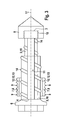
- FIG. 3 a second embodiment of the screw shaft 2 and the anchor bolt 1 is shown.
- the screw shaft 2 is divided into a first section 15 and a second section 16.
- the first section 15 has a smaller diameter than the second section 16, so that there is no form-fitting connection to the two sliding surfaces 11 between the screw shaft 2 and the fastening element 7 on the first section 15.
- the screw shaft 2 is releasably connected to the drill head 5 with a releasable connection device, for example a screw connection 18 or a bayonet connection.
- the screw shaft 2 can be set in a rotational movement without the fastener. 7 performs a rotational movement and the screw shaft 2 can be solved by means of the screw 18 of the drill head 5 and then screwed another screw shaft 2 in the drill head 5 and secured.
- the screw shaft 2 can also be designed as a drill pipe for incorporating the bore with the drill head 5, and only then is a screw shaft 2, for example of a different length, fastened to the drill head 5 by means of the screw connection 18 and thus ultimately Also, the screw shaft 2 secured with the fastener 7 in the bore.
- the anchor bolt 1 Due to the formation of the self-tapping thread 9 on the separate fastener 7 in addition to the screw shank 2, when cutting the self-tapping thread 9 in the material which limits the bore, the self-tapping thread 9 perform that axial movement due to the pitch of the self-tapping thread 9, which specifies the slope of the self-tapping thread 9. As a result, a particularly safe, reliable and high forces receiving positive connection between the self-tapping thread 9 and the material in the self-drilling anchor bolt 1 is possible. Furthermore, different fastening elements 7 with correspondingly adapted self-tapping threads 9 for different materials can be pushed onto an identical screw shank 2 with the drill head 5. As a result, with the anchor bolt 1, the connection between the self-tapping thread 9 and the material can be additionally improved.
Landscapes
- Engineering & Computer Science (AREA)
- General Engineering & Computer Science (AREA)
- Mechanical Engineering (AREA)
- Physics & Mathematics (AREA)
- Geometry (AREA)
- Joining Of Building Structures In Genera (AREA)
- Dowels (AREA)
- Connection Of Plates (AREA)
Abstract
Bei einer selbstbohrende Ankerschraube (1) zur Anwendung im Berg-, Tunnel-, Hoch- oder Tiefbau und zum Einschrauben in Gestein oder ein Bauwerk, umfassend einen Schraubenschaft (2), der ein vorderes Ende (3) und ein hinteres Ende (4) aufweist, einen an dem vorderen Ende (3) des Schraubenschaftes (2) ausgebildeten Bohrkopf (5), ein selbstschneidendes Gewinde (9) zur Befestigung der Ankerschraube (1) in einer mit dem Bohrkopf (5) eingearbeiteten Bohrung, soll die Ankerschraube (1) mit einem geringen technischen Aufwand preiswert und zuverlässig befestigt werden können. Diese Aufgabe wird dadurch gelöst, dass die Ankerschraube (1) ein Befestigungselement (7) als separates Bauteil in Ergänzung zu dem Schraubenschaft (2) umfasst und das selbstschneidende Gewinde (9) an dem Befestigungselement (7) ausgebildet ist.
Description
- Die vorliegende Erfindung betrifft eine Ankerschraube gemäß dem Oberbegriff des Anspruches 1 und ein Verfahren zur Befestigung einer Ankerschraube gemäß dem Oberbegriff des Anspruches 11.
- Ankerschrauben werden für die verschiedensten technischen Anwendungen eingesetzt, um an der Ankerschraube einen Gegenstand zu befestigen. Beispielsweise können mit Ankerschrauben im Hochbau an Wänden aus Beton Gegenstände befestigt werden oder im Tunnelbau im anstehenden Gestein ebenfalls mit einer Ankerschraube ein Gegenstand befestigt werden. Hierzu wird zunächst mit einem Bohrgerät eine Bohrung in das Material, zum Beispiel Gestein oder Beton, eingearbeitet und anschließend wird die Ankerschraube mit einem selbstschneidenden Gewinde in die Bohrung eingeschraubt, wobei der Durchmesser des selbstschneidenden Gewindes größer ist als der Durchmesser der Bohrung, sodass sich das selbstschneidende Gewinde in das Material selbst einschneidet und eine formschlüssige Verbindung zwischen dem Material und dem selbstschneidenden Gewinde herstellt. Dadurch sind jedoch zwei Arbeitsgänge erforderlich, nämlich zunächst das Einarbeiten der Bohrung mit einem Bohrer und anschließend das Einbringen der Ankerschraube.
- Abweichend hiervon sind auch selbstbohrende Ankerschrauben bekannt, welche über einen Bohrkopf an dem Schraubenschaft verfügen. Bei diesen selbstbohrenden Ankerschrauben kann in einem Arbeitsgang mit Hilfe des Bohrkopfes an einem vorderen Ende des Schraubenschaftes eine Bohrung in das Material eingearbeitet und mit dem selbstschneidenden Gewinde an dem Schraubenschaft eine formschlüssige Verbindung zwischen der Ankerschraube und dem die Bohrung begrenzenden Material hergestellt werden.
- Aus der
US 5 190 425 ist eine selbstbohrende Ankerschraube bekannt. Die Ankerschraube weist einen Schraubenschaft auf und an dem vorderen Ende des Schraubenschaftes ist ein Bohrkopf angeordnet. Ferner ist der Schraubenschaft mit einem selbstschneidenden Gewinde versehen und der Durchmesser des Schraubenschaftes im Bereich des selbstschneidenden Gewindes ohne dem selbstschneidenden Gewinde entspricht im Wesentlichen dem Durchmesser des Bohrkopfes. - Die
EP 1 760 331 A2 zeigt ein Befestigungselement für harte Untergründe, wie Betonmauerwerk oder dergleichen, mit einem zylinderförmigen Grundkörper, an dessen Außenseite zumindest bereichsweise ein selbstschneidendes Gewinde vorgesehen ist und der ein erstes Ende mit einem Bodenabschnitt sowie ein zweites, dem ersten Ende abgewandtes Ende aufweist, wobei der Grundkörper ein innenliegendes Angriffsmittel für ein Setzwerkzeug und eine zum zweiten Ende offene Aufnahme aufweist, die mit einem Lastangriffsmittel versehen ist, wobei sich die Aufnahme in Richtung des zweiten Endes an das Angriffsmittel anschließt, wobei das Angriffsmittel als durchgängige Öffnung im Bodenabschnitt ausgebildet ist. - Die Aufgabe der vorliegenden Erfindung besteht darin, eine Ankerschraube und ein Verfahren zur Befestigung einer Ankerschraube zur Verfügung zu stellen, bei denen die Ankerschraube mit einem geringen technischen Aufwand preiswert und zuverlässig befestigt werden kann.
- Diese Aufgabe wird gelöst mit einer selbstbohrenden Ankerschraube zur Anwendung im Berg-, Tunnel-, Hoch- oder Tiefbau und zum Einschrauben in Gestein oder ein Bauwerk, umfassend einen Schraubenschaft, der ein vorderes Ende und ein hinteres Ende aufweist, einen an dem vorderen Ende des Schraubenschaftes ausgebildeten Bohrkopf, ein selbstschneidendes Gewinde zur Befestigung der Ankerschraube in einer mit dem Bohrkopf eingearbeiteten Bohrung, wobei die Ankerschraube ein Befestigungselement als separates Bauteil in Ergänzung zu dem Schraubenschaft umfasst und das selbstschneidende Gewinde an dem Befestigungselement ausgebildet ist. Das selbstschneidende Gewinde ist damit von dem Schraubenschaft entkoppelt an einem separaten Bauteil ausgebildet. Dadurch können mit einem Schraubenschaft in vorteilhafter Weise für unterschiedliche Materialien unterschiedliche Arten von selbstschneidendem Gewinde zur Verfügung gestellt werden, indem lediglich ein anderes Befestigungselement auf den Schraubenschaft aufgeschoben ist oder angeordnet wird. Ferner ist es dadurch möglich, dass aufgrund der Ausbildung als separates Bauteil das Befestigungselement axial bezüglich des Schraubenschaftes verschiebbar ist.
- In einer zusätzlichen Ausgestaltung ist das Befestigungselement axial verschieblich an dem Schraubenschaft gelagert. Bei einer Ausbildung des selbstschneidenden Gewindes an dem Schraubenschaft kann mit dem selbstschneidenden Gewinde die Ankerschraube nur unzulänglich in dem Material befestigt werden, welches die Bohrung begrenzt. Beim Bohren der Bohrung mit einer selbstbohrenden Ankerschraube hängt die axiale Bohrbewegung von verschiedenen Umständen ab, insbesondere von dem anstehenden Gestein. Im Regelfall ist dabei die axiale Bewegung des Schraubenschaftes beim Bohren anders als die erforderliche axiale Bewegung aufgrund der Steigung des selbstschneidenden Gewindes. Somit kommt es im Stand der Technik zu Differenzen in der erforderlichen axialen Bewegung aufgrund der Steigung des selbstschneidenden Gewindes und der tatsächlichen axialen Geschwindigkeit aufgrund des Bohrfortschrittes mit dem Bohrkopf. Dadurch kann im Stand der Technik das selbstschneidende Gewinde dahingehend wirken, dass dieses das Material in Richtung zu dem Bohrlochmund fördert und somit die Festigkeit des Materials im Bereich des selbstschneidenden Gewindes vermindert und eine schlechtere Verbindung zwischen dem selbstschneidenden Gewinde und dem Material möglich ist. Bei einer erfindungsgemäßen Entkoppelung mit separaten Bauteilen des Befestigungselementes mit dem selbstschneidenden Gewinde, welches axial verschieblich auf dem Schraubenschaft gelagert ist, kann das Befestigungselement mit dem selbstschneidenden Gewinde axial entsprechend der Steigung des selbstschneidenden Gewindes in das Material eingeschraubt oder eingearbeitet werden.
- In einer zusätzlichen Variante ist das Befestigungselement, insbesondere als eine Hülse ausgebildet, mit einer Öffnung ausgebildet, innerhalb der Öffnung der Schraubenschaft angeordnet und außenseitig an dem Befestigungselement ist das selbstschneidende Gewinde ausgebildet.
- In einer ergänzenden Ausgestaltung ist von dem Schraubenschaft auf das Befestigungselement ein Drehmoment übertragbar, insbesondere mittels einer formschlüssigen Verbindung zwischen dem Befestigungselement an der Öffnung und dem Schraubenschaft. Zum Versetzen des Befestigungselementes in eine Rotationsbewegung mit einer Rotationsachse als einer Längsachse des Schraubenschaftes, kann somit der Schraubenschaft in eine Rotationsbewegung versetzt werden und diese wird auf das Befestigungselement übertragen, sodass dadurch das Befestigungselement in die Bohrung eingeschraubt wird.
- Zweckmäßig ist an dem Befestigungselement an der Öffnung und an dem Schraubenschaft jeweils wenigstens eine Gleitfläche ausgebildet, die jeweils aufeinander liegen, und eine axiale Gleitlagerung des Befestigungselementes an dem Schraubenschaft bewirken und vorzugsweise bildet die jeweils wenigstens eine Gleitfläche die formschlüssige Verbindung zur Übertragung des Drehmomentes zusätzlich aus.
- In einer ergänzenden Ausgestaltung weist die Öffnung des Befestigungselementes wenigstens eine Längsnut auf und zwischen der wenigstens einen Längsnut und dem Befestigungselement bildet sich ein Zwischenraum aus zur Durchleitung von Bohrmaterial und/oder eines Spülfluides. Durch die Längsnut kann dadurch in vorteilhafter Weise Bohrmaterial oder Spülfluid beim Bohren vom Bereich des Bohrkopfes zu dem Bohrlochmund gefördert werden und/oder Spülfluid vom Bohrlochmund zu dem Bohrkopf oder umgekehrt.
- Vorzugsweise ist der Außendurchmesser des Befestigungselementes ohne das selbstschneidende Gewinde gleich groß oder kleiner als der maximale Durchmesser des Bohrkopfes. Zweckmäßig ist der Außendurchmesser des Befestigungselementes ohne das selbstschneidende Gewinde weniger als 20, 10, 5, 3, 2 oder 1 % kleiner als der maximalen Durchmesser des Bohrkopfes. Das selbstschneidende Gewinde schneidet sich somit in das nicht von dem Bohrkopf bearbeitete Material ein.
- In einer zusätzlichen Ausgestaltung ist der Schraubenschaft außenseitig mit einer Profilierung zur Förderung des Bohrmateriales beim Bohren von dem Bohrkopf zu einem Bohrlochmund versehen und vorzugsweise ist die Profilierung schraubenlinienförmig, insbesondere teilschraubenlinienförmig, ausgebildet.
- In einer ergänzenden Variante ist der Schraubenschaft in einen ersten Abschnitt im Bereich des vorderen Endes und in einen zweiten Abschnitt im Bereich des hinteren Endes unterteilt und der Schraubenschaft weist an dem ersten Abschnitt einen kleinen Durchmesser auf als an dem zweiten Abschnitt, so dass das Befestigungselement bei einer axialen Anordnung an dem ersten Abschnitt keine formschlüssige Verbindung mit dem Schraubenschaft aufweist. Bei einer axialen Bewegung zum Einschrauben des Befestigungselements besteht somit an dem ersten Abschnitt keine formschlüssige Verbindung mit dem Schraubenschaft und dadurch ist von dem Schraubenschaft an dem ersten Abschnitt kein Drehmoment mehr auf das Befestigungselement übertragbar. Bei einer lösbaren Verbindung des Schraubenschaftes an dem Bohrkopf kann dadurch, zum Beispiel mittels einer Schraubverbindung, der Schraubenschaft aus dem Bohrkopf ausgeschraubt und anschließend anderer Schraubenschaft eingefügt werden und mit dem Bohrkopf verbunden, zum Beispiel mittels der Schraubverbindung oder einer Bajonettverbindung.
- Insbesondere ist der Schraubenschaft als ein Voll- oder ein Hohlquerschnitt ausgebildet und/oder an dem hinteren Ende des Schraubenschaftes ist ein Ankerkopf ausgebildet und/oder der Durchmesser des Befestigungselementes mit dem selbstschneidenden Gewinde ist größer als der maximale Durchmesser des Bohrkopfes, so dass mit dem eingeschraubten Befestigungselement der Bohrkopf und damit auch der mit dem Bohrkopf verbundene Schraubenschaft axial in der Bohrung befestigbar ist. An dem Ankerkopf ist vorzugsweise ein Mehrkant ausgebildet, um dadurch mittels eines Bohrwerkzeuges auf den Ankerkopf und damit auch auf den Schraubenschaft ein Drehmoment zur Bewegung des Schraubenschaftes aufbringen zu können.
- Erfindungsgemäßes Verfahren zur Befestigung einer Ankerschraube, insbesondere in dieser Schutzrechtsanmeldung beschriebenen Ankerschraube, mit den Schritten: Einarbeiten einer Bohrung mit einem an einem Schraubenschaft ausgebildeten Bohrkopf, Befestigen der Ankerschraube mit einem selbstschneidenden Gewinde der Ankerschraube in der Bohrung, wobei das selbstschneidende Gewinde während des Einschraubens in das die Bohrung begrenzende Material eine axiale Bewegung relativ zu dem Schraubenschaft in Richtung zu einem vorderen Ende des Schraubenschaftes ausführt.
- In einer zusätzlichen Ausgestaltung schneidet sich beim Einschrauben des selbstschneidenden Gewindes das Gewinde in das die Bohrung begrenzende Material, z. B. Gestein oder Beton, ein und/oder eine formschlüssige Verbindung wird zwischen dem Gewinde und dem die Bohrung begrenzenden Material hergestellt und/oder das selbstschneidende Gewinde ist an einem Befestigungselement ausgebildet als separates Bauteil zu dem Schraubenschaft und das Befestigungselement führt die axiale Bewegung relativ zu dem Schraubenschaft in Richtung zu einem vorderen Ende des Schraubenschaftes aus.
- In einer ergänzenden Variante wird das selbstschneidende Gewinde während des Bohrens mit dem Bohrkopf in das die Bohrung begrenzende Material eingeschraubt und vorzugsweise führt das Befestigungselement die Rotationsbewegung des Schraubenschaftes zum Bohren mit dem Bohrkopf mit aus aufgrund einer Verbindung zwischen dem Schraubenschaft und dem Befestigungselement, welche ein Drehmoment von dem Schraubenschaft auf das Befestigungselement überträgt.
- In einer weiteren Ausführungsform wird das selbstschneidende Gewinde nach dem, vorzugsweise teilweisen, Einarbeiten der Bohrung mit dem Bohrkopf in das die Bohrung begrenzende Material eingeschraubt.
- Zweckmäßig wird das Befestigungselement mit dem selbstschneidenden Gewinde axial bis zu dem Bohrkopf oder mit einem Abstand von weniger als 10cm, 5cm oder 2 cm bis zu dem Bohrkopf beim Einschrauben in das die Bohrung begrenzende Material bewegt und/oder der Bohrkopf liegt auf dem eingeschraubten Befestigungselement auf, so dass der Bohrkopf und damit auch der Schraubenschaft axial mit dem Befestigungselement in der Bohrung befestigt wird.
- In einer weiteren Ausgestaltung wird der Schraubenschaft mit dem Schraubenkopf manuell oder mit Bohrausrüstung in das Material eingebohrt.
- In einer ergänzenden Variante wird der Schraubenschaft mit dem Schraubenkopf drehend bzw. rotierend oder drehschlagend und/oder mit einer Flüssigkeit oder Luft gespült oder mit einer Absaugung in das Material eingebohrt.
- In einer zusätzlichen Ausführungsform ist zu Beginn des Einbohrens des Schraubenschaftes mit dem Bohrkopf das Befestigungselement axial im Bereich des hinteren Endes des Schraubenschaftes axial an dem Schraubenschaft angeordnet, so dass zu Beginn des Bohrvorganges sich das selbstschneidende Gewinde an dem Befestigungselement nicht in das die Bohrung begrenzende Material einschraubt.
- In einer weiteren Ausgestaltung schneidet sich erst nach einem teilweisen Einbohren oder nach einem vollständigen Einbohren in der Endbohrtiefe des Schraubenschaftes mit dem Bohrkopf das Befestigungselement mit dem selbstschneidenden Gewinde in das die Bohrung begrenzende Material ein, da das Befestigungselement zu Beginn des Bohrvorganges axial im Bereich des hinteren Endes des Schraubenschaftes axial an dem Schraubenschaft angeordnet ist und erst anschließend bewegt sich das Befestigungselement axial in Richtung zu dem vorderen Ende des Schraubenschaftes.
- In einer ergänzenden Variante wird erst nach einem Einbohren des Schraubenschaftes mit dem Bohrkopf das Befestigungselement auf dem Schraubenschaft aufgesteckt und manuell oder motorgetrieben eingeschraubt.
- In einer zusätzlichen Ausgestaltung wird nach dem Einbohren des Schraubenschaftes mit dem Bohrkopf ein erhärtbares Fixierungsmaterial, z. B. Kunstharz oder Zementmörtel, ein einen Raum zwischen der Ankerschraube und dem die Bohrung begrenzenden Material eingebracht. Damit kann die Tragfähigkeit der Ankerschraube mit einem Injektionsverfahren weiter erhöht werden.
- Vorzugsweise wird das erhärtbare Fixierungsmaterial durch einen Längskanal an dem Schraubenschaft bei einer Ausbildung des Schraubenschaftes als Hohlquerschnitt eingebracht.
- Zweckmäßig besteht die Ankerschraube wenigstens teilweise, insbesondere vollständig, aus Metall, z. B. Stahl, oder, vorzugsweise faserverstärktem Kunststoff, z. B. GFK.
- Im Nachfolgenden werden Ausführungsbeispiele der Erfindung unter Bezugnahme auf die beigefügten Zeichnungen näher beschrieben. Es zeigen:
- Fig. 1
- eine Seitenansicht eines Schraubenschaftes in einem ersten Ausführungsbeispiel und ein Befestigungselement in einem Längsschnitt,
- Fig. 2
- einen Querschnitt des Schraubenschaftes und des Befestigungselementes gemäß
Fig. 1 und - Fig. 3
- eine Seitenansicht des Schraubenschaftes in einem zweiten Ausführungsbeispiel und das Befestigungselement in einem Längsschnitt.
- Eine in
Fig. 1 und 2 in einem ersten Ausführungsbeispiel dargestellte selbstbohrende Ankerschraube 1 dient dazu, um mit Hilfe der Ankerschraube 1 einen Gegenstand zu befestigen. Die Ankerschraube 1 wird beispielsweise im Hochbau dazu eingesetzt, um an Betonwänden oder Decken Gegenstände zu befestigen oder im Bergbau, um im anstehenden Gestein im Tunnel ebenfalls einen Gegenstand zu befestigen. - Die Ankerschraube 1 weist einen Schraubenschaft 2 als Vollquerschnitt auf mit einem vorderen Ende 3 und einem hinteren Ende 4. Am vorderen Ende 3 ist an dem Schraubenschaft 2 ein Bohrkopf 5 befestigt und am hinteren Ende 4 des Schraubenschaftes 2 ist ein Ankerkopf 6 befestigt.
- Ein als Hülse 8 ausgebildetes Befestigungselement 7 weist eine Öffnung 10 auf. Das Befestigungselement 7 ist auf den Schraubenschaft 2 aufgeschoben (
Fig. 1 und 2 ), sodass dadurch der Schraubenschaft 2 innerhalb der Öffnung 10 des Befestigungselements 7 angeordnet ist. Das Befestigungselement 7 ist an seiner radialen Außenseite mit einem selbstschneidenden Gewinde 9 versehen. Die Öffnung 10 ist ferner mit zwei ebenen Gleitflächen 11 versehen und der Schraubenschaft 2 weist ebenfalls zwei ebene Gleitflächen 11 auf. Die beiden Gleitflächen 11 an dem Schraubenschaft 2 liegen auf den beiden Gleitflächen 11 an der Öffnung 10 des Befestigungselements 7 auf, sodass dadurch eine formschlüssige Verbindung zur Übertragung eines Drehmoments von dem Schraubenschaft 2 auf das Befestigungselement 7 besteht. Das Befestigungselement 7 weist ferner zwei Längsnuten 12 auf, sodass sich zwischen dem Befestigungselement 7 und dem Schraubenschaft 2 zwei Zwischenräume 13 ausbilden. Durch diese Zwischenräume 13 kann Bohrmaterial oder Spülfluid geleitet werden. Ferner ist der Schraubenschaft 2 außenseitig außerhalb der beiden Gleichflächen 11 mit einer schraubenlinienförmigen Profilierung 14 versehen. Mit Hilfe der Profilierung 14 kann Bohrmaterial von dem Bohrkopf 5 in Richtung zu dem hinteren Ende 4 bzw. einem Bohrlochmund einer mit dem Bohrkopf 5 einzuarbeitenden Bohrung gefördert werden. - Zum Befestigen der selbstbohrenden Ankerschraube 1, beispielsweise in einer Betonwand oder in anstehendem Gestein bei einem Tunnel, wird mit einem Bohrgerät auf den Ankerkopf 6 ein Drehmoment aufgebracht und dadurch der Ankerkopf 6, der Schraubenschaft 2 und der Bohrkopf 5 in eine Rotationsbewegung um die Längsachse 17 des Schraubenschaftes 2 versetzt. Dadurch wird mit dem Bohrkopf 5 eine Bohrung in das Material eingearbeitet und zu Beginn der Bohrung besteht kein Kontakt zwischen dem Befestigungselement 7 und dem Material, in welchem die Bohrung eingearbeitet wird, weil zu Beginn der Bohrung das Befestigungselement 7 im Bereich des hinteren Endes 4 des Schraubenschaftes 2, zum Beispiel aufliegend auf dem Ankerkopf 6, angeordnet ist. Erst mit Erreichen einer vorgegebenen Bohrlochtiefe kommt es zu einem Kontakt zwischen dem Befestigungselement 7 und dem Material, welches die Bohrung begrenzt. Dabei führt das Befestigungselement 7 die Dreh- bzw. Rotationsbewegung des Schraubenschaftes 2 um die Längsachse 17 mit aus, aufgrund der formschlüssigen Verbindung an den beiden Gleitflächen 11. Das selbstschneidende Gewinde 9 schneidet sich somit unabhängig vom Bohrfortschritt bzw. der axialen Bewegung während des Bohrens mit dem Bohrkopf 6 allein aufgrund der Steigung des selbstschneidenden Gewindes 9 in das Material ein und das Befestigungselement 7 bewegt sich in axialer Richtung in Richtung zu dem Bohrkopf 5 bzw. dem vorderen Ende 3 des Schraubenschaftes 2 bis das Befestigungselement 7 auf dem Bohrkopf 5 aufliegt. Nach oder kurz vor dem Aufliegen des Befestigungselements 7 an dem Bohrkopf 5 wird das Bohrgerät abgeschaltet und dadurch führen Schraubenschaft 2 und das Befestigungselement 7 keine Rotationsbewegung mehr aus. Das Befestigungselement 7 stellt mit dem selbstschneidenden Gewinde 9 eine formschlüssige Verbindung zwischen dem die Bohrung begrenzenden Material und dem selbstschneidenden Gewinde 9 her. Eine axiale Bewegung in Richtung zu dem Bohrlochmund ist dabei für den Schraubenschaft 2 ausgeschlossen, weil der Schraubenschaft 2 fest mit dem Bohrkopf 5 verbunden ist und der Bohrkopf 5 axial auf dem Befestigungselement 7 aufliegt (nicht dargestellt). Dadurch ist die Ankerschraube 1 fest in der Bohrung verankert.
- In
Fig. 3 ist ein zweites Ausführungsbeispiel des Schraubenschaftes 2 bzw. der Ankerschraube 1 dargestellt. Im Nachfolgenden werden im Wesentlichen nur die Unterschiede zu dem ersten Ausführungsbeispiel gemäßFig. 1 beschrieben. Der Schraubenschaft 2 ist in einen ersten Abschnitt 15 und in einen zweiten Abschnitt 16 unterteilt. Der erste Abschnitt 15 weist einen kleineren Durchmesser als der zweite Abschnitt 16 auf, sodass an dem ersten Abschnitt 15 keine formschlüssige Verbindung an den beiden Gleitflächen 11 zwischen dem Schraubenschaft 2 und dem Befestigungselement 7 besteht. Der Schraubenschaft 2 ist mit einer lösbaren Verbindungseinrichtung, zum Beispiel einer Schraubverbindung 18 oder einer Bajonettverbindung, lösbar mit dem Bohrkopf 5 verbunden. Nach dem Einarbeiten der Bohrung mit dem Bohrkopf 5 und dem Bewegen des Befestigungselements 7 vollständig zu dem ersten Abschnitt 15 an dem Bohrkopf 5 und dem Aufliegen des Befestigungselements 7 an dem Bohrkopf 5 kann somit der Schraubenschaft 2 in eine Rotationsbewegung versetzt werden ohne dass das Befestigungselement 7 eine Rotationsbewegung mit ausführt und der Schraubenschaft 2 kann mittels der Schraubverbindung 18 von dem Bohrkopf 5 gelöst und anschließend ein anderer Schraubenschaft 2 in den Bohrkopf 5 eingeschraubt und befestigt werden. Dabei kann der Schraubenschaft 2 zum Einarbeiten der Bohrung mit dem Bohrkopf 5 auch als ein Bohrgestänge ausgebildet sein und erst anschließend wird ein Schraubenschaft 2, beispielsweise mit einer anderen Länge, an dem Bohrkopf 5 mittels der Schraubverbindung 18 befestigt und damit letztendlich auch der Schraubenschaft 2 mit dem Befestigungselement 7 in der Bohrung befestigt. - Insgesamt betrachtet sind mit der erfindungsgemäßen Ankerschraube 1 wesentliche Vorteile verbunden. Aufgrund der Ausbildung des selbstschneidenden Gewindes 9 an dem separaten Befestigungselement 7 in Ergänzung zu dem Schraubenschaft 2 kann beim Einschneiden des selbstschneidenden Gewindes 9 in das Material, welches die Bohrung begrenzt, das selbstschneidende Gewinde 9 diejenige axiale Bewegung aufgrund der Steigung des selbstschneidenden Gewindes 9 ausführen, welche die Steigung des selbstschneidenden Gewindes 9 vorgibt. Dadurch ist eine besonders sichere, zuverlässige und hohe Kräfte aufnehmende formschlüssige Verbindung zwischen dem selbstschneidenden Gewinde 9 und dem Material bei der selbstbohrenden Ankerschraube 1 möglich. Ferner können an einem identischen Schraubenschaft 2 mit dem Bohrkopf 5 unterschiedliche Befestigungselemente 7 mit entsprechend angepassten selbstschneidenden Gewinden 9 für unterschiedliche Materialien aufgeschoben werden. Dadurch kann mit der Ankerschraube 1 die Verbindung zwischen dem selbstschneidenden Gewinde 9 und dem Material zusätzlich verbessert werden.
Claims (15)
- Selbstbohrende Ankerschraube (1) zur Anwendung im Berg-, Tunnel-, Hoch- oder Tiefbau und zum Einschrauben in Gestein oder ein Bauwerk, umfassend- einen Schraubenschaft (2), der ein vorderes Ende (3) und ein hinteres Ende (4) aufweist,- einen an dem vorderen Ende (3) des Schraubenschaftes (2) ausgebildeten Bohrkopf (5),- ein selbstschneidendes Gewinde (9) zur Befestigung der Ankerschraube (1) in einer mit dem Bohrkopf (5) eingearbeiteten Bohrung,dadurch gekennzeichnet, dass
die Ankerschraube (1) ein Befestigungselement (7) als separates Bauteil in Ergänzung zu dem Schraubenschaft (2) umfasst und das selbstschneidende Gewinde (9) an dem Befestigungselement (7) ausgebildet ist. - Ankerschraube nach Anspruch 1,
dadurch gekennzeichnet, dass
das Befestigungselement (7) axial verschieblich an dem Schraubenschaft (2) gelagert ist. - Ankerschraube nach Anspruch 1 oder 2,
dadurch gekennzeichnet, dass
das Befestigungselement (7), insbesondere als eine Hülse (8) ausgebildet, mit einer Öffnung (10) ausgebildet ist, innerhalb der Öffnung (10) der Schraubenschaft (2) angeordnet und außenseitig an dem Befestigungselement (7) das selbstschneidende Gewinde (9) ausgebildet ist. - Ankerschraube nach einem oder mehreren der vorhergehenden Ansprüche,
dadurch gekennzeichnet, dass
von dem Schraubenschaft (2) auf das Befestigungselement (7) ein Drehmoment übertragbar ist, insbesondere mittels einer formschlüssigen Verbindung zwischen dem Befestigungselement (7) an der Öffnung (10) und dem Schraubenschaft (2). - Ankerschraube nach einem oder mehreren der vorhergehenden Ansprüche,
dadurch gekennzeichnet, dass
an dem Befestigungselement (7) an der Öffnung (10) und an dem Schraubenschaft (2) jeweils wenigstens eine Gleitfläche (11) ausgebildet ist, die jeweils aufeinander liegen, und eine axiale Gleitlagerung des Befestigungselementes (7) an dem Schraubenschaft (2) bewirken und vorzugsweise die jeweils wenigstens eine Gleitfläche (11) die formschlüssige Verbindung zur Übertragung des Drehmomentes zusätzlich ausbildet. - Ankerschraube nach einem oder mehreren der Ansprüche 3 bis 5, dadurch gekennzeichnet, dass
die Öffnung (10) des Befestigungselementes (7) wenigstens eine Längsnut (12) aufweist und sich zwischen der wenigstens einen Längsnut (12) und dem Befestigungselement (7) ein Zwischenraum (13) ausbildet zur Durchleitung von Bohrmaterial und/oder eines Spülfluides. - Ankerschraube nach einem oder mehreren der vorhergehenden Ansprüche,
dadurch gekennzeichnet, dass
der Außendurchmesser des Befestigungselementes (7) ohne dem selbstschneidenden Gewinde (9) gleich groß oder kleiner ist als der maximale Durchmesser des Bohrkopfes (5). - Ankerschraube nach einem oder mehreren der vorhergehenden Ansprüche,
dadurch gekennzeichnet, dass
der Schraubenschaft (2) außenseitig mit einer Profilierung (14) zur Förderung des Bohrmateriales beim Bohren von dem Bohrkopf (5) zu einem Bohrlochmund versehen ist und vorzugsweise die Profilierung (14) schraubenlinienförmig, insbesondere teilschraubenlinienförmig, ausgebildet ist. - Ankerschraube nach einem oder mehreren der vorhergehenden Ansprüche,
dadurch gekennzeichnet, dass
der Schraubenschaft (2) in einen ersten Abschnitt (15) im Bereich des vorderen Endes (3) und in einen zweiten Abschnitt (16) im Bereich des hinteren Endes (4) unterteilt ist und der Schraubenschaft (2) an dem ersten Abschnitt (15) einen kleinen Durchmesser aufweist als an dem zweiten Abschnitt (16), so dass das Befestigungselement (7) bei einer axialen Anordnung an dem ersten Abschnitt (15) keine formschlüssige Verbindung mit dem Schraubenschaft (2) aufweist. - Ankerschraube nach einem oder mehreren der vorhergehenden
Ansprüche,
dadurch gekennzeichnet, dass
der Schraubenschaft (2) als ein Voll- oder ein Hohlquerschnitt ausgebildet ist
und/oder
an dem hinteren Ende (4) des Schraubenschaftes (2) ein Ankerkopf (6) ausgebildet ist
und/oder
der Durchmesser des Befestigungselementes (7) mit dem selbstschneidenden Gewinde (9) größer ist als der maximale Durchmesser des Bohrkopfes (5), so dass mit dem eingeschraubten Befestigungselement (7) der Bohrkopf (5) und damit auch der mit dem Bohrkopf (5) verbundene Schraubenschaft (2) axial in der Bohrung befestigbar ist. - Verfahren zur Befestigung einer Ankerschraube (1), insbesondere
einer Ankerschraube (1) gemäß einem oder mehreren der vorhergehenden Ansprüche, mit den Schritten:- Einarbeiten einer Bohrung mit einem an einem Schraubenschaft (2) ausgebildeten Bohrkopf (5),- Befestigen der Ankerschraube (1) mit einem selbstschneidenden Gewinde (9) der Ankerschraube (1) in der Bohrung,dadurch gekennzeichnet, dass
das selbstschneidende Gewinde (9) während des Einschraubens in das die Bohrung begrenzende Material eine axiale Bewegung relativ zu dem Schraubenschaft (2) in Richtung zu einem vorderen Ende (3) des Schraubenschaftes (2) ausführt. - Verfahren nach Anspruch 11,
dadurch gekennzeichnet, dass
beim Einschrauben des selbstschneidenden Gewindes (9) sich das Gewinde (9) in das die Bohrung begrenzende Material, z. B. Gestein oder Beton, einschneidet
und/oder
eine formschlüssige Verbindung zwischen dem Gewinde (9) und dem die Bohrung begrenzenden Material hergestellt wird und/oder
das selbstschneidende Gewinde (9) an einem Befestigungselement (7) ausgebildet ist als separates Bauteil zu dem Schraubenschaft (2) und das Befestigungselement (7) die axiale Bewegung relativ zu dem Schraubenschaft (2) in Richtung zu einem vorderen Ende (3) des Schraubenschaftes (2) ausführt. - Verfahren nach Anspruch 11 oder 12,
dadurch gekennzeichnet, dass
das selbstschneidende Gewinde (9) während des Bohrens mit dem Bohrkopf (5) in das die Bohrung begrenzende Material eingeschraubt wird und vorzugsweise das Befestigungselement (7) die Rotationsbewegung des Schraubenschaftes (2) zum Bohren mit dem Bohrkopf (5) mit ausführt aufgrund einer Verbindung zwischen dem Schraubenschaft (2) und dem Befestigungselement (7), welche ein Drehmoment von dem Schraubenschaft (2) auf das Befestigungselement (7) überträgt. - Verfahren nach einem oder mehreren der Ansprüche 11 oder 13, dadurch gekennzeichnet, dass
das selbstschneidende Gewinde (9) nach dem, vorzugsweise teilweisen, Einarbeiten der Bohrung mit dem Bohrkopf (5) in das die Bohrung begrenzende Material eingeschraubt wird. - Verfahren nach einem oder mehreren der Ansprüche 11 bis 14,
dadurch gekennzeichnet, dass
das Befestigungselement (7) mit dem selbstschneidenden Gewinde (9) axial bis zu dem Bohrkopf (5) oder mit einem Abstand von weniger als 10cm, 5cm oder 2 cm bis zu dem Bohrkopf (5) beim Einschrauben in das die Bohrung begrenzende Material bewegt wird und/oder
der Bohrkopf (5) auf dem eingeschraubten Befestigungselement (7) aufliegt, so dass der Bohrkopf (5) und damit auch der Schraubenschaft (2) axial mit dem Befestigungselement (7) in der Bohrung befestigt wird.
Applications Claiming Priority (1)
| Application Number | Priority Date | Filing Date | Title |
|---|---|---|---|
| DE102011077595A DE102011077595A1 (de) | 2011-06-16 | 2011-06-16 | Ankerschraube |
Publications (1)
| Publication Number | Publication Date |
|---|---|
| EP2535601A1 true EP2535601A1 (de) | 2012-12-19 |
Family
ID=46168207
Family Applications (1)
| Application Number | Title | Priority Date | Filing Date |
|---|---|---|---|
| EP12169002A Withdrawn EP2535601A1 (de) | 2011-06-16 | 2012-05-23 | Ankerschraube |
Country Status (7)
| Country | Link |
|---|---|
| US (1) | US20120321411A1 (de) |
| EP (1) | EP2535601A1 (de) |
| AU (1) | AU2012202534A1 (de) |
| CA (1) | CA2775548A1 (de) |
| DE (1) | DE102011077595A1 (de) |
| RU (1) | RU2012124763A (de) |
| ZA (1) | ZA201204428B (de) |
Cited By (1)
| Publication number | Priority date | Publication date | Assignee | Title |
|---|---|---|---|---|
| WO2020260238A1 (en) * | 2019-06-27 | 2020-12-30 | Hilti Aktiengesellschaft | Concrete screw with integrated washer with bulging underhead surface |
Families Citing this family (4)
| Publication number | Priority date | Publication date | Assignee | Title |
|---|---|---|---|---|
| US9133630B2 (en) | 2013-06-14 | 2015-09-15 | Dean Dougherty | Fastener anchor repair system and method |
| DE102016125201A1 (de) | 2016-12-21 | 2018-06-21 | Ludwig Hettich Holding Gmbh & Co. Kg | System zum Fügen oder Armieren von Bauteilen |
| CN112032168B (zh) * | 2020-08-28 | 2022-03-11 | 浙江全友标准件股份有限公司 | 一种自攻螺钉 |
| CN116658219B (zh) * | 2023-08-02 | 2023-10-13 | 阳泉市广凯机械制造有限公司 | 锚索预应力控制装置及使用方法 |
Citations (4)
| Publication number | Priority date | Publication date | Assignee | Title |
|---|---|---|---|---|
| US5190425A (en) | 1991-10-21 | 1993-03-02 | Illinois Tool Works Inc. | Anchor |
| EP1760331A2 (de) | 2005-09-02 | 2007-03-07 | HILTI Aktiengesellschaft | Befestigungselement für harte Untergründe |
| US20080008554A1 (en) * | 2006-06-07 | 2008-01-10 | Chien-Ming Lu | Self-drilling wall anchor device |
| US20080063488A1 (en) * | 2006-09-13 | 2008-03-13 | Ming Chia Cheng | Self-drilling wall anchor device |
Family Cites Families (4)
| Publication number | Priority date | Publication date | Assignee | Title |
|---|---|---|---|---|
| JP3405932B2 (ja) * | 1999-02-12 | 2003-05-12 | 株式会社ヤマヒロ | アンカーボルト及びその施工工具並びにその施工工具を用いたアンカーボルトの取付け施工方法 |
| AT410579B (de) * | 2001-06-01 | 2003-06-25 | Karl Hanl | Bohrschraube und werkzeug zum einbohren |
| US20060067803A1 (en) * | 2004-09-27 | 2006-03-30 | Hsu Chin J | Self-drilling wall anchor device |
| US20080292421A1 (en) * | 2007-05-22 | 2008-11-27 | Chin Hou Lin | Self-drilling wall anchor device |
-
2011
- 2011-06-16 DE DE102011077595A patent/DE102011077595A1/de not_active Withdrawn
-
2012
- 2012-04-25 CA CA2775548A patent/CA2775548A1/en not_active Abandoned
- 2012-05-01 AU AU2012202534A patent/AU2012202534A1/en not_active Abandoned
- 2012-05-23 EP EP12169002A patent/EP2535601A1/de not_active Withdrawn
- 2012-06-15 US US13/524,706 patent/US20120321411A1/en not_active Abandoned
- 2012-06-15 ZA ZA2012/04428A patent/ZA201204428B/en unknown
- 2012-06-15 RU RU2012124763/12A patent/RU2012124763A/ru not_active Application Discontinuation
Patent Citations (4)
| Publication number | Priority date | Publication date | Assignee | Title |
|---|---|---|---|---|
| US5190425A (en) | 1991-10-21 | 1993-03-02 | Illinois Tool Works Inc. | Anchor |
| EP1760331A2 (de) | 2005-09-02 | 2007-03-07 | HILTI Aktiengesellschaft | Befestigungselement für harte Untergründe |
| US20080008554A1 (en) * | 2006-06-07 | 2008-01-10 | Chien-Ming Lu | Self-drilling wall anchor device |
| US20080063488A1 (en) * | 2006-09-13 | 2008-03-13 | Ming Chia Cheng | Self-drilling wall anchor device |
Cited By (2)
| Publication number | Priority date | Publication date | Assignee | Title |
|---|---|---|---|---|
| WO2020260238A1 (en) * | 2019-06-27 | 2020-12-30 | Hilti Aktiengesellschaft | Concrete screw with integrated washer with bulging underhead surface |
| EP3757316A1 (de) * | 2019-06-27 | 2020-12-30 | Hilti Aktiengesellschaft | Betonschraube mit integrierter unterlegscheibe mit gewölbter unterkopfoberfläche |
Also Published As
| Publication number | Publication date |
|---|---|
| RU2012124763A (ru) | 2013-12-20 |
| US20120321411A1 (en) | 2012-12-20 |
| CA2775548A1 (en) | 2012-12-16 |
| ZA201204428B (en) | 2013-02-27 |
| AU2012202534A1 (en) | 2013-01-10 |
| DE102011077595A1 (de) | 2012-12-20 |
Similar Documents
| Publication | Publication Date | Title |
|---|---|---|
| EP2802786B1 (de) | Spreizanker | |
| DE2941769C2 (de) | Verfahren zum Setzen eines Ankerbolzens und Ankerbolzen | |
| EP0955476A2 (de) | Selbstschneidende Schraube zum Einsatz in Vollbaustoffen | |
| EP2233757A2 (de) | Verfahren zur Verankerung eines Befestigungselementes in einem mineralischen Bauteil sowie Befestigungselement für mineralische Bauteile | |
| EP1892425A2 (de) | Befestigungselement für harte Untergründe | |
| EP0988427B1 (de) | Verbindungselement zum verbinden von wenigstens zwei holzbauteilen und einer knotenplatte | |
| DE102011077595A1 (de) | Ankerschraube | |
| DE2535066A1 (de) | Verfahren zum spreizdruckfreien setzen von duebeln sowie werkzeug und duebel zur durchfuehrung des verfahrens | |
| WO2011103937A2 (de) | Bewehrungs- und/oder ankerschraube | |
| EP2691659B1 (de) | Befestigungs-anker sowie befestigungs-anker-anordnung | |
| EP2128458B1 (de) | Befestigungselement | |
| DE3718158C2 (de) | Vorrichtung zur Erzeugung einer Hinterschneidung in einem zylindrisch vorgebohrten Bohrloch | |
| AT510315B1 (de) | Anordnung zur, insbesondere distanzierten, befestigung zumindest einer dämmstoffplatte an einem gebäude | |
| WO2013131777A2 (de) | Gesteinsanker | |
| DE19634383A1 (de) | Verbindungs- und Befestigungsvorrichtung | |
| EP3959056B1 (de) | System und verfahren zum befestigen eines ankers in einem mineralischen untergrund sowie ein furchwerkzeug zum furchen eines innengewindes in einem bohrloch | |
| EP2009296B1 (de) | Chemisch verankerbares Befestigungselement | |
| EP3135927B1 (de) | Schraube zum einschrauben in ein bohrloch und anordnung mit einer derartigen schraube | |
| EP1400704A1 (de) | Einrichtung zur distanzierten Befestigung von Wärmedämmplatten an Wänden oder Decken | |
| EP2878739B1 (de) | Dämmstoffhalter zur Befestigung von Dämmstoffplatten an einen Untergrund | |
| DE8401123U1 (de) | Formschlußdübel für Beton | |
| EP0348545A1 (de) | Ankerbefestigung, Verfahren und Mittel zu deren Herstellung | |
| EP0881400A1 (de) | Befestigungsschraube, insbesondere Rohrschraube | |
| DE4205616A1 (de) | Anker zur verankerung mittels einer verbundmasse in einem bohrloch eines betonteils | |
| AT410579B (de) | Bohrschraube und werkzeug zum einbohren |
Legal Events
| Date | Code | Title | Description |
|---|---|---|---|
| PUAI | Public reference made under article 153(3) epc to a published international application that has entered the european phase |
Free format text: ORIGINAL CODE: 0009012 |
|
| AK | Designated contracting states |
Kind code of ref document: A1 Designated state(s): AL AT BE BG CH CY CZ DE DK EE ES FI FR GB GR HR HU IE IS IT LI LT LU LV MC MK MT NL NO PL PT RO RS SE SI SK SM TR |
|
| AX | Request for extension of the european patent |
Extension state: BA ME |
|
| STAA | Information on the status of an ep patent application or granted ep patent |
Free format text: STATUS: THE APPLICATION IS DEEMED TO BE WITHDRAWN |
|
| 18D | Application deemed to be withdrawn |
Effective date: 20130620 |