EP2535571B1 - Verfahren zur Optimierung der erzeugten Leistung einer Windkraftanlage durch Reduzierung der mechanischen Einwirkung auf die Struktur - Google Patents
Verfahren zur Optimierung der erzeugten Leistung einer Windkraftanlage durch Reduzierung der mechanischen Einwirkung auf die Struktur Download PDFInfo
- Publication number
- EP2535571B1 EP2535571B1 EP12290166.3A EP12290166A EP2535571B1 EP 2535571 B1 EP2535571 B1 EP 2535571B1 EP 12290166 A EP12290166 A EP 12290166A EP 2535571 B1 EP2535571 B1 EP 2535571B1
- Authority
- EP
- European Patent Office
- Prior art keywords
- rotor
- angle
- aerodynamic
- velocity
- blades
- Prior art date
- Legal status (The legal status is an assumption and is not a legal conclusion. Google has not performed a legal analysis and makes no representation as to the accuracy of the status listed.)
- Active
Links
- 238000000034 method Methods 0.000 title claims description 23
- 238000005259 measurement Methods 0.000 claims description 19
- 238000013507 mapping Methods 0.000 claims description 14
- 238000004519 manufacturing process Methods 0.000 claims description 9
- 230000003247 decreasing effect Effects 0.000 claims description 6
- 230000033228 biological regulation Effects 0.000 claims description 2
- 239000011295 pitch Substances 0.000 description 20
- 241000940835 Pales Species 0.000 description 12
- 206010033546 Pallor Diseases 0.000 description 12
- 238000011217 control strategy Methods 0.000 description 5
- ZZUFCTLCJUWOSV-UHFFFAOYSA-N furosemide Chemical compound C1=C(Cl)C(S(=O)(=O)N)=CC(C(O)=O)=C1NCC1=CC=CO1 ZZUFCTLCJUWOSV-UHFFFAOYSA-N 0.000 description 5
- 229920000297 Rayon Polymers 0.000 description 4
- 238000006073 displacement reaction Methods 0.000 description 4
- 239000002964 rayon Substances 0.000 description 4
- 230000005484 gravity Effects 0.000 description 3
- 238000005457 optimization Methods 0.000 description 3
- 241000897276 Termes Species 0.000 description 2
- 230000000694 effects Effects 0.000 description 2
- 238000011084 recovery Methods 0.000 description 2
- 230000015572 biosynthetic process Effects 0.000 description 1
- 238000013016 damping Methods 0.000 description 1
- 238000013461 design Methods 0.000 description 1
- 238000011161 development Methods 0.000 description 1
- 230000005611 electricity Effects 0.000 description 1
- 238000003786 synthesis reaction Methods 0.000 description 1
Images


Classifications
-
- F—MECHANICAL ENGINEERING; LIGHTING; HEATING; WEAPONS; BLASTING
- F03—MACHINES OR ENGINES FOR LIQUIDS; WIND, SPRING, OR WEIGHT MOTORS; PRODUCING MECHANICAL POWER OR A REACTIVE PROPULSIVE THRUST, NOT OTHERWISE PROVIDED FOR
- F03D—WIND MOTORS
- F03D7/00—Controlling wind motors
- F03D7/02—Controlling wind motors the wind motors having rotation axis substantially parallel to the air flow entering the rotor
- F03D7/022—Adjusting aerodynamic properties of the blades
- F03D7/0224—Adjusting blade pitch
-
- F—MECHANICAL ENGINEERING; LIGHTING; HEATING; WEAPONS; BLASTING
- F03—MACHINES OR ENGINES FOR LIQUIDS; WIND, SPRING, OR WEIGHT MOTORS; PRODUCING MECHANICAL POWER OR A REACTIVE PROPULSIVE THRUST, NOT OTHERWISE PROVIDED FOR
- F03D—WIND MOTORS
- F03D7/00—Controlling wind motors
- F03D7/02—Controlling wind motors the wind motors having rotation axis substantially parallel to the air flow entering the rotor
- F03D7/028—Controlling wind motors the wind motors having rotation axis substantially parallel to the air flow entering the rotor controlling wind motor output power
- F03D7/0292—Controlling wind motors the wind motors having rotation axis substantially parallel to the air flow entering the rotor controlling wind motor output power to reduce fatigue
-
- F—MECHANICAL ENGINEERING; LIGHTING; HEATING; WEAPONS; BLASTING
- F03—MACHINES OR ENGINES FOR LIQUIDS; WIND, SPRING, OR WEIGHT MOTORS; PRODUCING MECHANICAL POWER OR A REACTIVE PROPULSIVE THRUST, NOT OTHERWISE PROVIDED FOR
- F03D—WIND MOTORS
- F03D7/00—Controlling wind motors
- F03D7/02—Controlling wind motors the wind motors having rotation axis substantially parallel to the air flow entering the rotor
- F03D7/04—Automatic control; Regulation
- F03D7/042—Automatic control; Regulation by means of an electrical or electronic controller
- F03D7/043—Automatic control; Regulation by means of an electrical or electronic controller characterised by the type of control logic
- F03D7/045—Automatic control; Regulation by means of an electrical or electronic controller characterised by the type of control logic with model-based controls
-
- Y—GENERAL TAGGING OF NEW TECHNOLOGICAL DEVELOPMENTS; GENERAL TAGGING OF CROSS-SECTIONAL TECHNOLOGIES SPANNING OVER SEVERAL SECTIONS OF THE IPC; TECHNICAL SUBJECTS COVERED BY FORMER USPC CROSS-REFERENCE ART COLLECTIONS [XRACs] AND DIGESTS
- Y02—TECHNOLOGIES OR APPLICATIONS FOR MITIGATION OR ADAPTATION AGAINST CLIMATE CHANGE
- Y02E—REDUCTION OF GREENHOUSE GAS [GHG] EMISSIONS, RELATED TO ENERGY GENERATION, TRANSMISSION OR DISTRIBUTION
- Y02E10/00—Energy generation through renewable energy sources
- Y02E10/70—Wind energy
- Y02E10/72—Wind turbines with rotation axis in wind direction
Definitions
- the present invention relates to the field of renewable energies and more particularly the control of wind turbines.
- Wind turbines are designed to produce electricity as cheaply as possible.
- wind turbines are typically constructed to achieve maximum performance at around 15 m / s. It is in fact pointless to design wind turbines that maximize their efficiency at even higher wind speeds, which are infrequent. In case of wind speeds higher than 15 m / s, it is necessary to lose some of the additional energy contained in the wind in order to avoid damaging the wind turbine. All wind turbines are therefore designed with a power control system.
- Linear controllers have been widely used for power control by controlling the inclination angle of the blades (blade orientation).
- EP2 112 376 A2 and US 2006/0033338 A1 disclose alternative control strategies for wind turbines.
- the object of the invention relates to a method for optimizing the electrical energy production of a horizontal axis wind turbine by performing a non-linear control of the orientation of the blades taking into account the dynamics of the system, while minimizing the mechanical impact on the structure.
- the impact is minimized by changing the angle of inclination of the blades so that the aerodynamic force applied to the nacelle leads to zero speed from the top of the mast.
- the method is based in particular on a physical model of the aerodynamic force.
- the term defined so as to reduce speed variations of the top of the mast is proportional to a difference between the current values of positions and speeds of the mast and the reference values of positions and speeds of the mast.
- a positional reference value being a function of the aerodynamic force determined in step c)
- a speed reference value being a zero value.
- T aero 0.5 ⁇ ⁇ R b 3 vs q ⁇ , R b ⁇ r V w V w 2 )
- An objective of the method according to the invention is to maximize the energy production of a wind turbine with a horizontal axis (propeller perpendicular to the wind), implanted on land (onshore) or at sea (offshore), while limiting the extreme moments and the fatigue of the mechanical structure.
- the angle of inclination of the blades is sought to maximize the recovered power P aero as a function of the wind speed V w .
- the orientation of the blades is the angle between the blades and a reference such as the ground (horizontal plane, perpendicular to the mast of the wind turbine).
- This setpoint is determined as a function of the rotor speed measurement. This pair is determined to optimize the energy recovery under maximum power stress, by means of mapping.
- An example of such mapping is provided on the figure 5 , where T e is represented as a function of ⁇ r . ii - Generation of a rotor speed setpoint ⁇ r sp
- a rotor speed setpoint is determined ⁇ r sp .
- This setpoint is obtained by means of maps that are a function of the wind speed.
- mapping the parameter c q is presented on the figure 1 .
- This map indicates the value of the parameter c q according to the ratio R b ⁇ r V w , for different pitches (a curve for each ⁇ ). This type of mapping is well known to specialists.
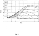
- the report R b ⁇ r V w is rated TSR on the Figures 1 to 3 .
- ⁇ r sp arg max ⁇ r 0.5 ⁇ ⁇ R b 3 vs q ⁇ , R b ⁇ r V w V w 2 * ⁇ r iii - Generating an aerodynamic torque setpoint T aero sp
- control strategy used is a dynamic control strategy that anticipates the setpoint variation and that corrects with two terms, a proportional term and an integral term.
- Another objective of the invention is to maximize the production of energy while limiting the extreme moments and the fatigue of the mechanical structure.
- we control the orientation of the blades that is to say that we change the setpoint ⁇ the angle ⁇ so as to obtain a compromise between recovered power and fatigue of the structure.
- the impact is minimized by changing the angle of inclination of the blades so that the aerodynamic force applied to the nacelle leads to zero speed from the top of the mast.
- the method is based in particular on a physical model of the aerodynamic force.
- mapping the parameter c t is presented on the figure 2 .
- This map indicates the value of the parameter c t according to the ratio R b ⁇ r V w , for different pitches (a curve for each ⁇ ). This type of mapping is well known to specialists.
- This force is the one that moves the gondola and influences the dynamics of the mast (and the platform if the wind turbine is installed at sea on a platform).
- F aerodynamic force
- a setpoint value of aerodynamic force produced on the nacelle is determined when the blades are oriented with said first angle, by decreasing said aerodynamic force determined in step c) by a proportional term defined so as to reduce the velocity variations of said mast (and of the platform if the wind turbine is implanted at sea on a platform).
- This instruction is intended to reduce fatigue and extreme moments of the structure.
- the reference value is the theoretical value that we wish to obtain: zero mast and platform speeds, and the position of the mast and the platform. F and the force imposed by the sea (F hydro ).
- mapping the parameter c p is presented on the figure 3 .
- This map indicates the value of the parameter c p according to the ratio R b ⁇ r V w , for different pitches (a curve for each ⁇ ).
- This type of mapping is well known to specialists.
- r a parameter that corresponds to the size ratio between the mast and the floating structure. This represents the position of the center of gravity.
- the control strategy will seek to generate an aerodynamic force different from F to minimize fatigue and extreme moments of the structure.
- F aero sp F ⁇ - k 1 k 2 k 3 k 4 X - X ref with k1, k2, k3, and k4 calibration parameters to be determined.
- the blades are oriented according to the angle of inclination calculated in the previous step.
Landscapes
- Engineering & Computer Science (AREA)
- Life Sciences & Earth Sciences (AREA)
- Sustainable Development (AREA)
- Sustainable Energy (AREA)
- Chemical & Material Sciences (AREA)
- Combustion & Propulsion (AREA)
- Mechanical Engineering (AREA)
- General Engineering & Computer Science (AREA)
- Physics & Mathematics (AREA)
- Fluid Mechanics (AREA)
- Wind Motors (AREA)
Claims (7)
- Verfahren zur Optimierung der Stromerzeugung eines Windrades mit horizontaler Achse, wobei das Windrad einen Masten umfasst, der eine Gondel trägt, die mit einem Rotor versehen ist, auf dem Flügel befestigt sind, wobei ein Neigungswinkel der Flügel kontrolliert wird, dadurch gekennzeichnet, dass es die folgenden Schritte umfasst:a) Bestimmung eines ersten Neigungswinkels der Flügel, der es ermöglicht, die rückgewonnene Leistung zu maximieren, mit Hilfe der folgenden Schritte:i) Erzeugung eines elektrischen Drehmomentsollwerts Tsp r des Rotors in Abhängigkeit von einer Messung einer Rotorgeschwindigkeit;ii) Erzeugung eines Rotorgeschwindigkeitssollwerts Ωsp r in Abhängigkeit von einer Messung einer Windgeschwindigkeit Vwr mit Hilfe von Kartographien;iii) Erzeugung eines aerodynamischen Drehmomentsollwerts Tsp aero, um diesen Rotorgeschwindigkeitssollwert zu verfolgen;iv) Bestimmung des ersten Neigungswinkels, der es ermöglicht, dieses aerodynamische Drehmoment zu verwirklichen und die Regelung der Geschwindigkeit des Rotors zu gewährleisten.b) Auswahl eines aerodynamischen Kraftmodells, um eine auf der Gondel erzeugte aerodynamische Kraft in Abhängigkeit von einer Windgeschwindigkeit, einem Neigungswinkel und einer Geschwindigkeit des Rotors zu modellieren;c) Bestimmung der auf der Gondel erzeugten aerodynamischen Kraft, wenn die Flügel mit dem ersten Winkel ausgerichtet sind;d) Bestimmung eines Sollwerts einer auf der Gondel erzeugten aerodynamischen Kraft, wenn die Flügel mit dem ersten Winkel ausgerichtet sind, wobei die in Schritt c) bestimmte aerodynamische Kraft durch einen definieren Term verringert wird, um Geschwindigkeitsvariationen der Spitze des Masten zu verringern;e) Bestimmung eines zweiten Neigungswinkels der Flügel, der es ermöglicht, den Sollwert einer aerodynamischen Kraft zu erhalten, wobei das aerodynamische Kraftmodell umgekehrt wird und eine Messung einer Windgeschwindigkeit, eine Messung einer Rotorgeschwindigkeit und der Sollwert einer aerodynamischen Kraft verwendet werden; undf) Ausrichten der Flügel nach dem zweiten Winkel.
- Verfahren nach Anspruch 1, bei dem der definierte Term, um Geschwindigkeitsvariationen der Spitze des Masten zu verringern, zu einer Abweichung zwischen aktuellen Positions- und Geschwindigkeitswerten des Masten und Positions- und Geschwindigkeitsreferenzwerten des Masten proportional ist, wobei ein Positionsreferenzwert von der in Schritt c) bestimmten aerodynamischen Kraft abhängt, und ein Geschwindigkeitsreferenzwert ein Nullwert ist.
- Verfahren nach einem der vorhergehenden Ansprüche, bei dem das aerodynamische Kraftmodell in Abhängigkeit von der Windgeschwindigkeit Vwr, dem Neigungswinkel θ und der Geschwindigkeit des Rotors Ωr folgendermaßen geschrieben wird:
 - Rb : Radius des Rotors;-: Dicht der Luft;
 - ct : Parameter, der aus der Kartographie stammt und von
- Verfahren nach Anspruch 3, bei dem zu dem Term entsprechend der Geschwindigkeit des Windes des aerodynamischen Kraftmodells ein Term proportional zur Torsion des Masten hinzugefügt wird.
- Verfahren nach einem der vorhergehenden Ansprüche, bei dem der erste Neigungswinkel der Flügel bestimmt wird, der es ermöglicht, die rückgewonnene Leistung zu optimieren, wobei die folgenden Schritte durchgeführt werden:a) Auswahl eines aerodynamischen Kraftmodells, um das auf der Gondel erzeugte aerodynamische Drehmoment in Abhängigkeit von einer Windgeschwindigkeit Vwr, dem Neigungswinkel und einer Geschwindigkeit des Rotors Ω zu modellieren;b) Bestimmung eines Sollwerts eines aerodynamischen Drehmoments mit Hilfe des Modells;c) Bestimmung des ersten Neigungswinkels der Flügel, der es ermöglicht, den Sollwert eine aerodynamischen Drehmoments zu erhalten, wobei das aerodynamische Drehmomentmodell umgekehrt wird und eine Messung einer Windgeschwindigkeit, eine Messung einer Rotorgeschwindigkeit und der Sollwert eines aerodynamischen Drehmoments verwendet werden.
- Verfahren nach Anspruch 5, bei dem das aerodynamische Drehmomentmodell folgendermaßen geschrieben wird:
 - Rb : Radius des Rotors;-: Dicht der Luft;- cq : Parameter, der aus der Kartographie stammt und
- Verfahren nach Anspruch 6, bei dem zu dem Term entsprechend der Geschwindigkeit des Windes des aerodynamischen Drehmomentmodells ein Term proportional zur Torsion des Masten hinzugefügt wird.
Applications Claiming Priority (1)
| Application Number | Priority Date | Filing Date | Title |
|---|---|---|---|
| FR1101879A FR2976630B1 (fr) | 2011-06-17 | 2011-06-17 | Procede pour optimiser la puissance recuperee par une eolienne en reduisant l'impact mecanique sur la structure. |
Publications (2)
| Publication Number | Publication Date |
|---|---|
| EP2535571A1 EP2535571A1 (de) | 2012-12-19 |
| EP2535571B1 true EP2535571B1 (de) | 2018-10-17 |
Family
ID=46168368
Family Applications (1)
| Application Number | Title | Priority Date | Filing Date |
|---|---|---|---|
| EP12290166.3A Active EP2535571B1 (de) | 2011-06-17 | 2012-05-16 | Verfahren zur Optimierung der erzeugten Leistung einer Windkraftanlage durch Reduzierung der mechanischen Einwirkung auf die Struktur |
Country Status (5)
| Country | Link |
|---|---|
| US (1) | US10041473B2 (de) |
| EP (1) | EP2535571B1 (de) |
| DK (1) | DK2535571T3 (de) |
| ES (1) | ES2710336T3 (de) |
| FR (1) | FR2976630B1 (de) |
Families Citing this family (14)
| Publication number | Priority date | Publication date | Assignee | Title |
|---|---|---|---|---|
| CN103514353A (zh) * | 2012-06-29 | 2014-01-15 | 国际商业机器公司 | 新增风机的功率预测方法和系统 |
| US9316205B2 (en) * | 2013-03-15 | 2016-04-19 | Frontier Wind, Llc | Determining loads using various sensor locations |
| CN103441537B (zh) * | 2013-06-18 | 2018-04-13 | 国家电网公司 | 配有储能电站的分散式风电场有功优化调控方法 |
| FR3013777B1 (fr) | 2013-11-25 | 2015-11-13 | IFP Energies Nouvelles | Procede de controle et de surveillance d'une eolienne au moyen d'une estimation de la vitesse du vent au moyen d'un capteur lidar |
| FR3088434B1 (fr) | 2018-11-12 | 2020-11-13 | Ifp Energies Now | Procede de determination d’un facteur d’induction pour une eolienne equipee d’un capteur de teledetection par laser |
| FR3094093B1 (fr) | 2019-03-18 | 2021-03-05 | Ifp Energies Now | Procédé de prédiction de la vitesse du vent dans le plan du rotor pour une éolienne équipée d’un capteur de télédétection par Laser |
| FR3095246B1 (fr) | 2019-04-16 | 2022-12-09 | Ifp Energies Now | Procédé et système de contrôle d’une grandeur d’une éolienne par choix du contrôleur par un apprentissage automatique |
| FR3097644B1 (fr) | 2019-06-19 | 2021-06-11 | Ifp Energies Now | Procédé de détermination du profil vertical de la vitesse du vent en amont d’une éolienne équipée d’un capteur de télédétection par Laser |
| FR3107094B1 (fr) | 2020-02-10 | 2022-02-11 | Ifp Energies Now | Procédé de détermination de la vitesse du vent dans le plan du rotor d’une éolienne |
| FR3107095B1 (fr) | 2020-02-10 | 2022-02-11 | Ifp Energies Now | Procédé de détermination de la direction du vent au moyen d’un capteur de télédétection par Laser |
| FR3114881B1 (fr) | 2020-10-01 | 2022-09-09 | Ifp Energies Now | Procédé de détermination de la vitesse moyenne du vent au moyen d’un capteur de télédétection par Laser |
| FR3115115B1 (fr) | 2020-10-14 | 2022-10-14 | Ifp Energies Now | Procédé de détermination d’un facteur d’induction entre un plan de mesure et le plan du rotor d’une éolienne |
| FR3116123B1 (fr) | 2020-11-06 | 2022-10-14 | Ifp Energies Now | Procédé de détermination de la vitesse du vent dans le plan du rotor d’une éolienne |
| FR3126248B1 (fr) | 2021-08-20 | 2023-07-28 | Ifp Energies Now | Procédé de détermination de la vitesse du vent au moyen d’un capteur de télédétection par Laser monté sur une éolienne |
Family Cites Families (4)
| Publication number | Priority date | Publication date | Assignee | Title |
|---|---|---|---|---|
| US7317260B2 (en) * | 2004-05-11 | 2008-01-08 | Clipper Windpower Technology, Inc. | Wind flow estimation and tracking using tower dynamics |
| US20100014969A1 (en) | 2006-10-02 | 2010-01-21 | Kitchener Clark Wilson | Wind turbine with blade pitch control to compensate for wind shear and wind misalignment |
| US7942629B2 (en) | 2008-04-22 | 2011-05-17 | General Electric Company | Systems and methods involving wind turbine towers for power applications |
| NL2001878C2 (nl) * | 2008-08-07 | 2010-02-09 | Stichting Energie | Systeem en werkwijze voor compensatie van rotoronbalans voor een windturbine. |
-
2011
- 2011-06-17 FR FR1101879A patent/FR2976630B1/fr active Active
-
2012
- 2012-05-16 EP EP12290166.3A patent/EP2535571B1/de active Active
- 2012-05-16 DK DK12290166.3T patent/DK2535571T3/en active
- 2012-05-16 ES ES12290166T patent/ES2710336T3/es active Active
- 2012-06-08 US US13/491,686 patent/US10041473B2/en active Active
Non-Patent Citations (1)
| Title |
|---|
| None * |
Also Published As
| Publication number | Publication date |
|---|---|
| US20120321463A1 (en) | 2012-12-20 |
| FR2976630B1 (fr) | 2021-07-23 |
| DK2535571T3 (en) | 2019-02-18 |
| EP2535571A1 (de) | 2012-12-19 |
| US10041473B2 (en) | 2018-08-07 |
| FR2976630A1 (fr) | 2012-12-21 |
| ES2710336T3 (es) | 2019-04-24 |
Similar Documents
| Publication | Publication Date | Title |
|---|---|---|
| EP2535571B1 (de) | Verfahren zur Optimierung der erzeugten Leistung einer Windkraftanlage durch Reduzierung der mechanischen Einwirkung auf die Struktur | |
| EP2904265B1 (de) | Verfahren zur steuerung einer windenergieanlage mit einer geschätzten windgeschwindigkeit | |
| EP2642121B1 (de) | Verfahren zur Steuerung einer Windkraftanlage durch Optimierung ihrer Energieerzeugung bei gleichzeitiger Minimierung der mechanischen Auswirkung auf ihr Getriebe | |
| CN103541861B (zh) | 浮动式风电机组塔架负阻尼抑制系统和方法 | |
| CN110446853A (zh) | 用于管理风力涡轮机塔架的扭转振荡的系统和方法 | |
| CN102562491B (zh) | 风力涡轮机以及操作架设在水体中的风力涡轮机的方法 | |
| CN102644546B (zh) | 风力涡轮机的叶片载荷减少 | |
| JP5101689B2 (ja) | 風力発電装置及び風力発電装置のヨー旋回制御方法 | |
| EP2422080B1 (de) | Gewinnung von wellenenergie in einer windturbinenanlage | |
| US20130302161A1 (en) | Controller of wind turbine and wind turbine | |
| Wang et al. | A method for modeling of floating vertical axis wind turbine | |
| CN104153942A (zh) | 风力涡轮和用于控制风力涡轮载荷的方法 | |
| EP2981710B1 (de) | Verfahren zur steuerung der axiallast bei einer windturbine | |
| EP3862563B1 (de) | Verfahren zur bestimmung der windrichtung mithilfe eines laserfernerkennungssensors | |
| Namik et al. | State-space control of tower motion for deepwater floating offshore wind turbines | |
| EP3862560B1 (de) | Verfahren zur bestimmung der windgeschwindigkeit in der rotorebene einer windkraftanlage | |
| CN113323804B (zh) | 解决风力发电机组塔架二阶前后振动的控制方法与模块 | |
| Natili et al. | Experimental analysis of yaw by individual pitch control | |
| Rozehnal et al. | Performance analysis of a horizontal axis wind turbine | |
| FR3126248A1 (fr) | Procédé de détermination de la vitesse du vent au moyen d’un capteur de télédétection par Laser monté sur une éolienne | |
| Xudong et al. | Shape design and aerodynamic characteristics of wind turbine blades based on energy cost | |
| Sirigu et al. | Innovative blade design for wind generator application | |
| CN109667717A (zh) | 风力发电装置的控制系统、风力发电装置及控制方法 |
Legal Events
| Date | Code | Title | Description |
|---|---|---|---|
| PUAI | Public reference made under article 153(3) epc to a published international application that has entered the european phase |
Free format text: ORIGINAL CODE: 0009012 |
|
| AK | Designated contracting states |
Kind code of ref document: A1 Designated state(s): AL AT BE BG CH CY CZ DE DK EE ES FI FR GB GR HR HU IE IS IT LI LT LU LV MC MK MT NL NO PL PT RO RS SE SI SK SM TR |
|
| AX | Request for extension of the european patent |
Extension state: BA ME |
|
| 17P | Request for examination filed |
Effective date: 20130619 |
|
| RBV | Designated contracting states (corrected) |
Designated state(s): AL AT BE BG CH CY CZ DE DK EE ES FI FR GB GR HR HU IE IS IT LI LT LU LV MC MK MT NL NO PL PT RO RS SE SI SK SM TR |
|
| STAA | Information on the status of an ep patent application or granted ep patent |
Free format text: STATUS: EXAMINATION IS IN PROGRESS |
|
| 17Q | First examination report despatched |
Effective date: 20170221 |
|
| RAP1 | Party data changed (applicant data changed or rights of an application transferred) |
Owner name: IFP ENERGIES NOUVELLES |
|
| GRAP | Despatch of communication of intention to grant a patent |
Free format text: ORIGINAL CODE: EPIDOSNIGR1 |
|
| STAA | Information on the status of an ep patent application or granted ep patent |
Free format text: STATUS: GRANT OF PATENT IS INTENDED |
|
| INTG | Intention to grant announced |
Effective date: 20180601 |
|
| RIN1 | Information on inventor provided before grant (corrected) |
Inventor name: CREFF, YANN Inventor name: CHAUVIN, JONATHAN |
|
| GRAS | Grant fee paid |
Free format text: ORIGINAL CODE: EPIDOSNIGR3 |
|
| GRAA | (expected) grant |
Free format text: ORIGINAL CODE: 0009210 |
|
| STAA | Information on the status of an ep patent application or granted ep patent |
Free format text: STATUS: THE PATENT HAS BEEN GRANTED |
|
| AK | Designated contracting states |
Kind code of ref document: B1 Designated state(s): AL AT BE BG CH CY CZ DE DK EE ES FI FR GB GR HR HU IE IS IT LI LT LU LV MC MK MT NL NO PL PT RO RS SE SI SK SM TR |
|
| REG | Reference to a national code |
Ref country code: GB Ref legal event code: FG4D Free format text: NOT ENGLISH |
|
| REG | Reference to a national code |
Ref country code: CH Ref legal event code: EP |
|
| REG | Reference to a national code |
Ref country code: IE Ref legal event code: FG4D Free format text: LANGUAGE OF EP DOCUMENT: FRENCH |
|
| REG | Reference to a national code |
Ref country code: DE Ref legal event code: R096 Ref document number: 602012052266 Country of ref document: DE Ref country code: AT Ref legal event code: REF Ref document number: 1054343 Country of ref document: AT Kind code of ref document: T Effective date: 20181115 |
|
| REG | Reference to a national code |
Ref country code: DK Ref legal event code: T3 Effective date: 20190211 |
|
| REG | Reference to a national code |
Ref country code: NL Ref legal event code: FP |
|
| REG | Reference to a national code |
Ref country code: LT Ref legal event code: MG4D |
|
| REG | Reference to a national code |
Ref country code: AT Ref legal event code: MK05 Ref document number: 1054343 Country of ref document: AT Kind code of ref document: T Effective date: 20181017 |
|
| REG | Reference to a national code |
Ref country code: NO Ref legal event code: CREP Representative=s name: TANDBERG INNOVATION AS, POSTBOKS 1570 VIKA, 0118 Ref country code: NO Ref legal event code: T2 Effective date: 20181017 |
|
| REG | Reference to a national code |
Ref country code: ES Ref legal event code: FG2A Ref document number: 2710336 Country of ref document: ES Kind code of ref document: T3 Effective date: 20190424 |
|
| PG25 | Lapsed in a contracting state [announced via postgrant information from national office to epo] |
Ref country code: FI Free format text: LAPSE BECAUSE OF FAILURE TO SUBMIT A TRANSLATION OF THE DESCRIPTION OR TO PAY THE FEE WITHIN THE PRESCRIBED TIME-LIMIT Effective date: 20181017 Ref country code: BG Free format text: LAPSE BECAUSE OF FAILURE TO SUBMIT A TRANSLATION OF THE DESCRIPTION OR TO PAY THE FEE WITHIN THE PRESCRIBED TIME-LIMIT Effective date: 20190117 Ref country code: LV Free format text: LAPSE BECAUSE OF FAILURE TO SUBMIT A TRANSLATION OF THE DESCRIPTION OR TO PAY THE FEE WITHIN THE PRESCRIBED TIME-LIMIT Effective date: 20181017 Ref country code: HR Free format text: LAPSE BECAUSE OF FAILURE TO SUBMIT A TRANSLATION OF THE DESCRIPTION OR TO PAY THE FEE WITHIN THE PRESCRIBED TIME-LIMIT Effective date: 20181017 Ref country code: PL Free format text: LAPSE BECAUSE OF FAILURE TO SUBMIT A TRANSLATION OF THE DESCRIPTION OR TO PAY THE FEE WITHIN THE PRESCRIBED TIME-LIMIT Effective date: 20181017 Ref country code: LT Free format text: LAPSE BECAUSE OF FAILURE TO SUBMIT A TRANSLATION OF THE DESCRIPTION OR TO PAY THE FEE WITHIN THE PRESCRIBED TIME-LIMIT Effective date: 20181017 Ref country code: IS Free format text: LAPSE BECAUSE OF FAILURE TO SUBMIT A TRANSLATION OF THE DESCRIPTION OR TO PAY THE FEE WITHIN THE PRESCRIBED TIME-LIMIT Effective date: 20190217 Ref country code: AT Free format text: LAPSE BECAUSE OF FAILURE TO SUBMIT A TRANSLATION OF THE DESCRIPTION OR TO PAY THE FEE WITHIN THE PRESCRIBED TIME-LIMIT Effective date: 20181017 |
|
| PG25 | Lapsed in a contracting state [announced via postgrant information from national office to epo] |
Ref country code: AL Free format text: LAPSE BECAUSE OF FAILURE TO SUBMIT A TRANSLATION OF THE DESCRIPTION OR TO PAY THE FEE WITHIN THE PRESCRIBED TIME-LIMIT Effective date: 20181017 Ref country code: PT Free format text: LAPSE BECAUSE OF FAILURE TO SUBMIT A TRANSLATION OF THE DESCRIPTION OR TO PAY THE FEE WITHIN THE PRESCRIBED TIME-LIMIT Effective date: 20190217 Ref country code: RS Free format text: LAPSE BECAUSE OF FAILURE TO SUBMIT A TRANSLATION OF THE DESCRIPTION OR TO PAY THE FEE WITHIN THE PRESCRIBED TIME-LIMIT Effective date: 20181017 Ref country code: GR Free format text: LAPSE BECAUSE OF FAILURE TO SUBMIT A TRANSLATION OF THE DESCRIPTION OR TO PAY THE FEE WITHIN THE PRESCRIBED TIME-LIMIT Effective date: 20190118 Ref country code: SE Free format text: LAPSE BECAUSE OF FAILURE TO SUBMIT A TRANSLATION OF THE DESCRIPTION OR TO PAY THE FEE WITHIN THE PRESCRIBED TIME-LIMIT Effective date: 20181017 |
|
| PGFP | Annual fee paid to national office [announced via postgrant information from national office to epo] |
Ref country code: NL Payment date: 20190527 Year of fee payment: 8 |
|
| REG | Reference to a national code |
Ref country code: DE Ref legal event code: R097 Ref document number: 602012052266 Country of ref document: DE |
|
| PG25 | Lapsed in a contracting state [announced via postgrant information from national office to epo] |
Ref country code: CZ Free format text: LAPSE BECAUSE OF FAILURE TO SUBMIT A TRANSLATION OF THE DESCRIPTION OR TO PAY THE FEE WITHIN THE PRESCRIBED TIME-LIMIT Effective date: 20181017 Ref country code: IT Free format text: LAPSE BECAUSE OF FAILURE TO SUBMIT A TRANSLATION OF THE DESCRIPTION OR TO PAY THE FEE WITHIN THE PRESCRIBED TIME-LIMIT Effective date: 20181017 |
|
| PLBE | No opposition filed within time limit |
Free format text: ORIGINAL CODE: 0009261 |
|
| STAA | Information on the status of an ep patent application or granted ep patent |
Free format text: STATUS: NO OPPOSITION FILED WITHIN TIME LIMIT |
|
| PG25 | Lapsed in a contracting state [announced via postgrant information from national office to epo] |
Ref country code: SM Free format text: LAPSE BECAUSE OF FAILURE TO SUBMIT A TRANSLATION OF THE DESCRIPTION OR TO PAY THE FEE WITHIN THE PRESCRIBED TIME-LIMIT Effective date: 20181017 Ref country code: EE Free format text: LAPSE BECAUSE OF FAILURE TO SUBMIT A TRANSLATION OF THE DESCRIPTION OR TO PAY THE FEE WITHIN THE PRESCRIBED TIME-LIMIT Effective date: 20181017 Ref country code: SK Free format text: LAPSE BECAUSE OF FAILURE TO SUBMIT A TRANSLATION OF THE DESCRIPTION OR TO PAY THE FEE WITHIN THE PRESCRIBED TIME-LIMIT Effective date: 20181017 Ref country code: RO Free format text: LAPSE BECAUSE OF FAILURE TO SUBMIT A TRANSLATION OF THE DESCRIPTION OR TO PAY THE FEE WITHIN THE PRESCRIBED TIME-LIMIT Effective date: 20181017 |
|
| 26N | No opposition filed |
Effective date: 20190718 |
|
| PG25 | Lapsed in a contracting state [announced via postgrant information from national office to epo] |
Ref country code: SI Free format text: LAPSE BECAUSE OF FAILURE TO SUBMIT A TRANSLATION OF THE DESCRIPTION OR TO PAY THE FEE WITHIN THE PRESCRIBED TIME-LIMIT Effective date: 20181017 |
|
| REG | Reference to a national code |
Ref country code: CH Ref legal event code: PL |
|
| PG25 | Lapsed in a contracting state [announced via postgrant information from national office to epo] |
Ref country code: CH Free format text: LAPSE BECAUSE OF NON-PAYMENT OF DUE FEES Effective date: 20190531 Ref country code: LI Free format text: LAPSE BECAUSE OF NON-PAYMENT OF DUE FEES Effective date: 20190531 Ref country code: MC Free format text: LAPSE BECAUSE OF FAILURE TO SUBMIT A TRANSLATION OF THE DESCRIPTION OR TO PAY THE FEE WITHIN THE PRESCRIBED TIME-LIMIT Effective date: 20181017 |
|
| REG | Reference to a national code |
Ref country code: BE Ref legal event code: MM Effective date: 20190531 |
|
| PG25 | Lapsed in a contracting state [announced via postgrant information from national office to epo] |
Ref country code: LU Free format text: LAPSE BECAUSE OF NON-PAYMENT OF DUE FEES Effective date: 20190516 |
|
| PG25 | Lapsed in a contracting state [announced via postgrant information from national office to epo] |
Ref country code: TR Free format text: LAPSE BECAUSE OF FAILURE TO SUBMIT A TRANSLATION OF THE DESCRIPTION OR TO PAY THE FEE WITHIN THE PRESCRIBED TIME-LIMIT Effective date: 20181017 |
|
| PG25 | Lapsed in a contracting state [announced via postgrant information from national office to epo] |
Ref country code: IE Free format text: LAPSE BECAUSE OF NON-PAYMENT OF DUE FEES Effective date: 20190516 |
|
| PG25 | Lapsed in a contracting state [announced via postgrant information from national office to epo] |
Ref country code: BE Free format text: LAPSE BECAUSE OF NON-PAYMENT OF DUE FEES Effective date: 20190531 |
|
| REG | Reference to a national code |
Ref country code: NL Ref legal event code: MM Effective date: 20200601 |
|
| PG25 | Lapsed in a contracting state [announced via postgrant information from national office to epo] |
Ref country code: NL Free format text: LAPSE BECAUSE OF NON-PAYMENT OF DUE FEES Effective date: 20200601 |
|
| REG | Reference to a national code |
Ref country code: NO Ref legal event code: MMEP |
|
| PG25 | Lapsed in a contracting state [announced via postgrant information from national office to epo] |
Ref country code: CY Free format text: LAPSE BECAUSE OF FAILURE TO SUBMIT A TRANSLATION OF THE DESCRIPTION OR TO PAY THE FEE WITHIN THE PRESCRIBED TIME-LIMIT Effective date: 20181017 |
|
| PG25 | Lapsed in a contracting state [announced via postgrant information from national office to epo] |
Ref country code: NO Free format text: LAPSE BECAUSE OF NON-PAYMENT OF DUE FEES Effective date: 20200531 Ref country code: MT Free format text: LAPSE BECAUSE OF FAILURE TO SUBMIT A TRANSLATION OF THE DESCRIPTION OR TO PAY THE FEE WITHIN THE PRESCRIBED TIME-LIMIT Effective date: 20181017 Ref country code: HU Free format text: LAPSE BECAUSE OF FAILURE TO SUBMIT A TRANSLATION OF THE DESCRIPTION OR TO PAY THE FEE WITHIN THE PRESCRIBED TIME-LIMIT; INVALID AB INITIO Effective date: 20120516 |
|
| REG | Reference to a national code |
Ref country code: NO Ref legal event code: REIN Owner name: IFP ENERGIES NOUVELLES, FR Effective date: 20211206 |
|
| PG25 | Lapsed in a contracting state [announced via postgrant information from national office to epo] |
Ref country code: MK Free format text: LAPSE BECAUSE OF FAILURE TO SUBMIT A TRANSLATION OF THE DESCRIPTION OR TO PAY THE FEE WITHIN THE PRESCRIBED TIME-LIMIT Effective date: 20181017 |
|
| PGFP | Annual fee paid to national office [announced via postgrant information from national office to epo] |
Ref country code: NO Payment date: 20230519 Year of fee payment: 12 Ref country code: FR Payment date: 20230523 Year of fee payment: 12 Ref country code: ES Payment date: 20230612 Year of fee payment: 12 Ref country code: DK Payment date: 20230524 Year of fee payment: 12 Ref country code: DE Payment date: 20230530 Year of fee payment: 12 |
|
| PGFP | Annual fee paid to national office [announced via postgrant information from national office to epo] |
Ref country code: GB Payment date: 20230523 Year of fee payment: 12 |