EP2535546B1 - Combined heat and power device - Google Patents
Combined heat and power device Download PDFInfo
- Publication number
- EP2535546B1 EP2535546B1 EP12170885.3A EP12170885A EP2535546B1 EP 2535546 B1 EP2535546 B1 EP 2535546B1 EP 12170885 A EP12170885 A EP 12170885A EP 2535546 B1 EP2535546 B1 EP 2535546B1
- Authority
- EP
- European Patent Office
- Prior art keywords
- heater head
- power plant
- combustion chamber
- combined heat
- plant according
- Prior art date
- Legal status (The legal status is an assumption and is not a legal conclusion. Google has not performed a legal analysis and makes no representation as to the accuracy of the status listed.)
- Not-in-force
Links
Images
Classifications
-
- F—MECHANICAL ENGINEERING; LIGHTING; HEATING; WEAPONS; BLASTING
- F02—COMBUSTION ENGINES; HOT-GAS OR COMBUSTION-PRODUCT ENGINE PLANTS
- F02G—HOT GAS OR COMBUSTION-PRODUCT POSITIVE-DISPLACEMENT ENGINE PLANTS; USE OF WASTE HEAT OF COMBUSTION ENGINES; NOT OTHERWISE PROVIDED FOR
- F02G1/00—Hot gas positive-displacement engine plants
- F02G1/04—Hot gas positive-displacement engine plants of closed-cycle type
- F02G1/043—Hot gas positive-displacement engine plants of closed-cycle type the engine being operated by expansion and contraction of a mass of working gas which is heated and cooled in one of a plurality of constantly communicating expansible chambers, e.g. Stirling cycle type engines
- F02G1/053—Component parts or details
- F02G1/055—Heaters or coolers
-
- F—MECHANICAL ENGINEERING; LIGHTING; HEATING; WEAPONS; BLASTING
- F02—COMBUSTION ENGINES; HOT-GAS OR COMBUSTION-PRODUCT ENGINE PLANTS
- F02G—HOT GAS OR COMBUSTION-PRODUCT POSITIVE-DISPLACEMENT ENGINE PLANTS; USE OF WASTE HEAT OF COMBUSTION ENGINES; NOT OTHERWISE PROVIDED FOR
- F02G1/00—Hot gas positive-displacement engine plants
- F02G1/04—Hot gas positive-displacement engine plants of closed-cycle type
- F02G1/043—Hot gas positive-displacement engine plants of closed-cycle type the engine being operated by expansion and contraction of a mass of working gas which is heated and cooled in one of a plurality of constantly communicating expansible chambers, e.g. Stirling cycle type engines
- F02G1/045—Controlling
- F02G1/047—Controlling by varying the heating or cooling
-
- F—MECHANICAL ENGINEERING; LIGHTING; HEATING; WEAPONS; BLASTING
- F24—HEATING; RANGES; VENTILATING
- F24H—FLUID HEATERS, e.g. WATER OR AIR HEATERS, HAVING HEAT-GENERATING MEANS, e.g. HEAT PUMPS, IN GENERAL
- F24H8/00—Fluid heaters characterised by means for extracting latent heat from flue gases by means of condensation
-
- F—MECHANICAL ENGINEERING; LIGHTING; HEATING; WEAPONS; BLASTING
- F02—COMBUSTION ENGINES; HOT-GAS OR COMBUSTION-PRODUCT ENGINE PLANTS
- F02G—HOT GAS OR COMBUSTION-PRODUCT POSITIVE-DISPLACEMENT ENGINE PLANTS; USE OF WASTE HEAT OF COMBUSTION ENGINES; NOT OTHERWISE PROVIDED FOR
- F02G2254/00—Heat inputs
- F02G2254/10—Heat inputs by burners
-
- F—MECHANICAL ENGINEERING; LIGHTING; HEATING; WEAPONS; BLASTING
- F02—COMBUSTION ENGINES; HOT-GAS OR COMBUSTION-PRODUCT ENGINE PLANTS
- F02G—HOT GAS OR COMBUSTION-PRODUCT POSITIVE-DISPLACEMENT ENGINE PLANTS; USE OF WASTE HEAT OF COMBUSTION ENGINES; NOT OTHERWISE PROVIDED FOR
- F02G2254/00—Heat inputs
- F02G2254/15—Heat inputs by exhaust gas
-
- F—MECHANICAL ENGINEERING; LIGHTING; HEATING; WEAPONS; BLASTING
- F02—COMBUSTION ENGINES; HOT-GAS OR COMBUSTION-PRODUCT ENGINE PLANTS
- F02G—HOT GAS OR COMBUSTION-PRODUCT POSITIVE-DISPLACEMENT ENGINE PLANTS; USE OF WASTE HEAT OF COMBUSTION ENGINES; NOT OTHERWISE PROVIDED FOR
- F02G2254/00—Heat inputs
- F02G2254/50—Dome arrangements for heat input
-
- F—MECHANICAL ENGINEERING; LIGHTING; HEATING; WEAPONS; BLASTING
- F02—COMBUSTION ENGINES; HOT-GAS OR COMBUSTION-PRODUCT ENGINE PLANTS
- F02G—HOT GAS OR COMBUSTION-PRODUCT POSITIVE-DISPLACEMENT ENGINE PLANTS; USE OF WASTE HEAT OF COMBUSTION ENGINES; NOT OTHERWISE PROVIDED FOR
- F02G2255/00—Heater tubes
- F02G2255/20—Heater fins
-
- F—MECHANICAL ENGINEERING; LIGHTING; HEATING; WEAPONS; BLASTING
- F24—HEATING; RANGES; VENTILATING
- F24H—FLUID HEATERS, e.g. WATER OR AIR HEATERS, HAVING HEAT-GENERATING MEANS, e.g. HEAT PUMPS, IN GENERAL
- F24H1/00—Water heaters, e.g. boilers, continuous-flow heaters or water-storage heaters
- F24H1/22—Water heaters other than continuous-flow or water-storage heaters, e.g. water heaters for central heating
- F24H1/40—Water heaters other than continuous-flow or water-storage heaters, e.g. water heaters for central heating with water tube or tubes
- F24H1/43—Water heaters other than continuous-flow or water-storage heaters, e.g. water heaters for central heating with water tube or tubes helically or spirally coiled
-
- Y—GENERAL TAGGING OF NEW TECHNOLOGICAL DEVELOPMENTS; GENERAL TAGGING OF CROSS-SECTIONAL TECHNOLOGIES SPANNING OVER SEVERAL SECTIONS OF THE IPC; TECHNICAL SUBJECTS COVERED BY FORMER USPC CROSS-REFERENCE ART COLLECTIONS [XRACs] AND DIGESTS
- Y02—TECHNOLOGIES OR APPLICATIONS FOR MITIGATION OR ADAPTATION AGAINST CLIMATE CHANGE
- Y02B—CLIMATE CHANGE MITIGATION TECHNOLOGIES RELATED TO BUILDINGS, e.g. HOUSING, HOUSE APPLIANCES OR RELATED END-USER APPLICATIONS
- Y02B30/00—Energy efficient heating, ventilation or air conditioning [HVAC]
-
- Y—GENERAL TAGGING OF NEW TECHNOLOGICAL DEVELOPMENTS; GENERAL TAGGING OF CROSS-SECTIONAL TECHNOLOGIES SPANNING OVER SEVERAL SECTIONS OF THE IPC; TECHNICAL SUBJECTS COVERED BY FORMER USPC CROSS-REFERENCE ART COLLECTIONS [XRACs] AND DIGESTS
- Y02—TECHNOLOGIES OR APPLICATIONS FOR MITIGATION OR ADAPTATION AGAINST CLIMATE CHANGE
- Y02E—REDUCTION OF GREENHOUSE GAS [GHG] EMISSIONS, RELATED TO ENERGY GENERATION, TRANSMISSION OR DISTRIBUTION
- Y02E20/00—Combustion technologies with mitigation potential
- Y02E20/30—Technologies for a more efficient combustion or heat usage
Definitions
- the invention relates to a combined heat and power plant according to the preamble of patent claim 1.
- a combined heat and power plant of the type mentioned is after US 5 711 232 A known.
- a system which has a combustion chamber for the combustion of both solid and fluid fuels.
- the combustion chamber seen in the main flow direction in a known manner, an exhaust gas train downstream for removing an exhaust gas formed during combustion.
- this system has a hot gas engine, namely a Stirling engine, with a trained for heat exchange with the exhaust heater head. This is in the form of reaching into the flue exhaust tubes.
- This plant consists of a boiler with a combustion chamber for the combustion of a fuel, in this case a biomass solid fuel, namely wood.
- a combustion chamber seen in the main flow direction in a known manner, an exhaust gas train downstream for removing an exhaust gas formed during combustion.
- this system has a hot gas engine, namely a Stirling engine, with a trained for heat exchange with the exhaust heater head.
- This heater head is arranged in this system in the lower region of the combustion chamber, seen in the main flow direction of the exhaust gas in front of the flue gas.
- the invention has for its object to improve a combined heat and power plant of the type mentioned, in particular from the aspect of a more compact design and, consequently, a more efficient use of heat with the help of the Stirling engine.
- the heater head is arranged at the other end of the combustion chamber.
- the exhaust gas produced during the combustion only after the passage of the exhaust gas train which - which will be explained below - is particularly preferably designed as a heat exchanger, (directly) comes into contact with the heater head.
- the heater head which is preferably provided with a multiplicity of heat transfer fins for surface enlargement, is not contaminated and is therefore not impaired in its efficiency.
- the interposition of the flue gas between the combustion chamber and the heater head thus has the consequence that possible combustion residues can settle in the flue gas before reaching the heater head.
- the cleaning of the exhaust gas train is considerably easier than the cleaning of the geometrically complex heater head of the hot gas engine.
- the heater head is connected downstream of the flue
- first exhaust gas train or primary heat exchanger
- second exhaust gas train or secondary heat exchanger
- the heater head is not arranged directly in or at least at the outlet of the combustion chamber as in the aforementioned prior art, since possible combustion residues in this case directly pollute the heat transfer fins on the heater head, but only after a (possibly first) flue gas.
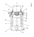
- the one in the only one FIG. 1 shown cogeneration plant consists initially in a known manner from a boiler 1 with a combustion chamber 2 for combustion of a fuel.
- This combustion chamber 2 is seen in the main flow direction (indicated by arrows) downstream of an exhaust 3 for the removal of an exhaust gas formed during combustion.
- the combined heat and power plant is made a hot gas engine 4 (in particular Stirling engine) with a heater head 5 designed for heat exchange with the exhaust gas.
- the fuel is the use of a fluid fuel provided, in particular oil, but also gas.
- FIG. 1 it can be seen, at one end of the combustion chamber 2, a burner 14 and at the other end of the combustion chamber 2, the heater head 5 is arranged.
- the combustion chamber 2 is cylindrical, wherein on one end face of the burner 14 and on the other end face of the heater head 5 is arranged.
- the heater head 5 is formed downstream of the exhaust gas 3 in the main flow direction of the exhaust gas seen.
- the heat transfer lamellae 10 are arranged like a wreath around a lamellar-free, preferably dome-shaped surface region 11 of the heater head 5.
- This lamellar surface area 11 of the heater head 5 is how FIG. 1 shows, formed with an outside of a preferably also dome-shaped combustion chamber 12 thermally connected.
- thermally related is to be understood that either the surface area 11 and the combustion chamber 12 directly touch or at least a material (such as nonwoven, stainless steel wool or the like) is disposed between the two components, which ensures good heat transfer.
- the combustion chamber 2 is provided away from the heater head with at least one opening 13 for the exhaust gas train 3.
- the exhaust gas 3 is formed as the combustion chamber 2 at least partially enclosing annular gap space and at least partially thermally connected with a water-carrying space 15, wherein the water-carrying space 15 is particularly preferred and formed as an annular gap the exhaust gas 3 is at least partially enclosing.
- the exhaust gas 3 is formed in a conventional manner as a heat exchanger, as a primary heat exchanger.
- main longitudinal axes of the combustion chamber 2, the exhaust gas duct 3 and the hot gas engine 4 are parallel to each other, here even superposed, formed.
- a shut-off element 6 is arranged between the exhaust gas 3 and the heater head 5.
- the heater head 5 is formed by a chamber 7 provided with openings 7 enclosed, wherein the exhaust gas 3 is formed via the openings 7 with the chamber 8 connectable.
- the shut-off element 6 is thus provided for closing on demand (this will be discussed below) of the openings 7.
- the shut-off element 6 (which is in FIG. 1 is not shown in detail) either temperature-dependent automatically (for example via a bimetal) or via a (mechanical or electromechanical) actuator operably formed.
- FIG. 1 illustrated preferably provided that the heater head 5 of the hot gas engine 4 between the exhaust 3 and a Nachschaltebenleyer 9 (secondary heat exchanger or second flue) is arranged.
- This Nachschaltebenleyer 9 is arranged at the heater head side end of the combustion chamber 2 and a helically wound coil heat exchanger, the heater head 5 at least partially enclosing and (as in the WO 2007/079730 A1 ) formed by the exhaust gas radially from the inside to the outside.
- the combined heat and power plant functions as follows:
- the burner 14 is used to burn a fluid fuel, in particular oil.
- the resulting exhaust gas flows in FIG. 1 from left to right in the combustion chamber 2.
- a Strömungsumschelement 16 may be arranged. With this Strömungsumschelement 16, the heat input of the burner 14 opposite end face of the combustion chamber 2 can be influenced. This may be necessary if the maximum amount of heat is not to be transferred to the combustion chamber wall 12 and thus to the lamellar-free surface area 11 of the heater head 5.
- the exhaust gas flows as a sheath flow back toward the burner 14 is deflected in the region of the burner 14 and passed through the opening 13 formed as an annular gap in the exhaust gas 3. Since the exhaust gas 3 is enclosed by a space 15 flowed through by the heating circuit water, the exhaust gas is cooled when passing through the exhaust gas train 3, which thus serves as a primary heat exchanger.
- the exhaust gas is in any case passed through the Nachschaltebenleyer 9 (second flue) to be further cooled there again.
- the exhaust gas can also flow into the chamber 8, in which the heating head 5 provided with heat-transfer fins 10 is located.
- the openings 7 In FIG. 1 are the openings 7 to about 1/4 to 1/3 closed. The position of the shut-off element 6 can influence how much heat is transferred to the heater head 5.
- shut-off element 6 releases the openings 7 at low power, ie the hot exhaust gas can transfer its heat to the chamber 8 and thus to the heat transfer plate 10 delivered. If the burner 14, however, operated at a higher power, the access to the chamber 8 is closed with the shut-off 6, because the heater head 5 is already supplied via the rear wall of the combustion chamber (combustion chamber 12) enough heat to ensure a constant hot gas engine operation.
Description
Die Erfindung betrifft eine Kraft-Wärme-Kopplungsanlage gemäß dem Oberbegriff des Patentanspruchs 1.The invention relates to a combined heat and power plant according to the preamble of
Eine Kraft-Wärme-Kopplungsanlage der eingangs genannten Art ist nach
Weiterhin wird darauf verwiesen, dass eine Kraft-Wärme-Kopplungsanlage ähnlich der eingangs genannten Art von der schweizer Firma Hovalwerk AG unter der Bezeichnung AgroLyt - Stirling BHKW gebaut und angeboten wird. Diese Anlage besteht aus einem Heizkessel mit einer Brennkammer zur Verbrennung eines Brennstoffs, und zwar in diesem Fall eines Biomasse-Festbrennstoffs, nämlich Holz. Dabei ist der Brennkammer in Hauptströmungsrichtung gesehen in bekannter Weise ein Abgaszug zur Abfuhr eines bei der Verbrennung entstandenen Abgases nachgeschaltet. Außerdem weist diese Anlage einen Heißgasmotor, nämlich einen Stirlingmotor, mit einem zum Wärmeaustausch mit dem Abgas ausgebildeten Erhitzerkopf auf. Dieser Erhitzerkopf ist bei dieser Anlage im unteren Bereich der Brennkammer, in Hauptströmungsrichtung des Abgases gesehen vor dem Abgaszug angeordnet.Furthermore, it is pointed out that a combined heat and power plant similar to the type mentioned by the Swiss company Hovalwerk AG under the name AgroLyt - Stirling CHP is built and offered. This plant consists of a boiler with a combustion chamber for the combustion of a fuel, in this case a biomass solid fuel, namely wood. In this case, the combustion chamber seen in the main flow direction in a known manner, an exhaust gas train downstream for removing an exhaust gas formed during combustion. In addition, this system has a hot gas engine, namely a Stirling engine, with a trained for heat exchange with the exhaust heater head. This heater head is arranged in this system in the lower region of the combustion chamber, seen in the main flow direction of the exhaust gas in front of the flue gas.
Der Erfindung liegt die Aufgabe zugrunde, eine Kraft-Wärme-Kopplungsanlage der eingangs genannten Art zu verbessern, und zwar insbesondere unter dem Aspekt einer kompakteren Bauform und damit einhergehend einer effizienteren Wärmenutzung mit Hilfe des Stirlingmotors.The invention has for its object to improve a combined heat and power plant of the type mentioned, in particular from the aspect of a more compact design and, consequently, a more efficient use of heat with the help of the Stirling engine.
Diese Aufgabe ist mit einer Kraft-Wärme-Kopplungsanlage der eingangs genannten Art durch die im Kennzeichen des Patentanspruchs 1 aufgeführten Merkmale gelöst.This object is achieved with a combined heat and power plant of the type mentioned by the features listed in the characterizing part of
Nach der Erfindung ist also vorgesehen, dass am anderen Ende der Brennkammer der Erhitzerkopf angeordnet ist.According to the invention, it is thus provided that the heater head is arranged at the other end of the combustion chamber.
Es ist dabei dafür gesorgt, dass das bei der Verbrennung entstehende Abgas erst nach der Passage des Abgaszuges, der - was weiter unten noch erläutert wird - besonders bevorzugt als Wärmetauscher ausgebildet ist, (direkt) mit dem Erhitzerkopf in Kontakt kommt. Hierdurch ist erheblich besser dafür gesorgt, dass der zur Oberflächenvergrößerung vorzugsweise mit einer Vielzahl von Wärmeübertragungslamellen versehene Erhitzerkopf nicht verschmutzt und dadurch in seinem Wirkungsgrad nicht beeinträchtigt wird. Die Zwischenschaltung des Abgaszuges zwischen die Brennkammer und den Erhitzerkopf hat somit zur Folge, dass sich mögliche Verbrennungsrückstände vor dem Erreichen des Erhitzerkopfes im Abgaszug absetzen können. Die Reinigung des Abgaszuges ist erheblich einfacher als die Reinigung des geometrisch komplexen Erhitzerkopfes des Heißgasmotors.It is thereby ensured that the exhaust gas produced during the combustion only after the passage of the exhaust gas train, which - which will be explained below - is particularly preferably designed as a heat exchanger, (directly) comes into contact with the heater head. As a result, it is considerably better ensured that the heater head, which is preferably provided with a multiplicity of heat transfer fins for surface enlargement, is not contaminated and is therefore not impaired in its efficiency. The interposition of the flue gas between the combustion chamber and the heater head thus has the consequence that possible combustion residues can settle in the flue gas before reaching the heater head. The cleaning of the exhaust gas train is considerably easier than the cleaning of the geometrically complex heater head of the hot gas engine.
Bezüglich der Maßgabe, dass der Erhitzerkopf dem Abgaszug nachgeschaltet ist, wird darauf hingewiesen, dass neben dem insofern ersten Abgaszug (oder auch Primärwärmetauscher) regelmäßig auch ein zweiter Abgaszug (oder auch Sekundärwärmetauscher) vorgesehen ist, der wiederum in Hauptströmungsrichtung gesehen dem Erhitzerkopf nachgeschaltet ist. Wesentlich ist also, dass der Erhitzerkopf nicht wie beim eingangs genannten Stand der Technik unmittelbar in oder jedenfalls am Ausgang der Brennkammer angeordnet ist, da mögliche Verbrennungsrückstände in diesem Fall direkt die Wärmeübertragungslamellen am Erhitzerkopf verschmutzen, sondern erst nach einem (gegebenenfalls ersten) Abgaszug.With respect to the proviso that the heater head is connected downstream of the flue, it is noted that in addition to the insofar as the first exhaust gas train (or primary heat exchanger) is regularly provided also a second exhaust gas train (or secondary heat exchanger), which in turn is followed in the main flow direction of the heater head. It is therefore essential that the heater head is not arranged directly in or at least at the outlet of the combustion chamber as in the aforementioned prior art, since possible combustion residues in this case directly pollute the heat transfer fins on the heater head, but only after a (possibly first) flue gas.
Andere vorteilhafte Weiterbildungen ergeben sich aus den abhängigen Patentansprüchen.Other advantageous developments emerge from the dependent claims.
Die erfindungsgemäße Kraft-Wärme-Kopplungsanlage einschließlich ihrer vorteilhaften Weiterbildungen gemäß der abhängigen Patentansprüche wird nachfolgend anhand der zeichnerischen Darstellung eines bevorzugten Ausführungsbeispiels näher erläutert.The combined heat and power plant according to the invention including its advantageous developments according to the dependent claims will be explained in more detail with reference to the drawing of a preferred embodiment.
Es zeigt
Figur 1- schematisch und im Schnitt die erfindungsgemäße Kraft-Wärme-Kopplungsanlage.
- FIG. 1
- schematically and in section, the inventive combined heat and power plant.
Die in der einzigen
Bei der erfindungsgemäßen Kraft-Wärme-Kopplungsanlage ist als Brennstoff die Verwendung eines fluiden Brennstoffs vorgesehen, und zwar insbesondere Öl, aber auch Gas.In the combined heat and power plant of the invention, the fuel is the use of a fluid fuel provided, in particular oil, but also gas.
Wie aus
Ferner ist vorgesehen, dass der Erhitzerkopf 5 dem Abgaszug 3 in Hauptströmungsrichtung des Abgases gesehen nachgeschaltet ausgebildet ist.It is further provided that the heater head 5 is formed downstream of the
Wie bereits erläutert, ist auf diese Weise gewährleistet, dass sich Verbrennungsrückstände auf dem Weg zum Erhitzerkopf 5 im Abgaszug 3 absetzen können, so dass eine Verschmutzung des Erhitzerkopfes 5 vermieden werden kann.As already explained, it is ensured in this way that combustion residues on the way to the heater head 5 can settle in the
Dies gilt umso mehr, wenn der Erhitzerkopf 5, wie bevorzugt und in
Weiterhin ist bevorzugt vorgesehen, dass die Wärmeübertragungslamellen 10 kranzartig um einen lamellenfreien, vorzugsweise kalottenförmigen Oberflächenbereich 11 des Erhitzerkopfes 5 angeordnet sind. Dieser lamellenfreie Oberflächenbereich 11 des Erhitzerkopfes 5 ist dabei, wie
Ferner ist vorgesehen, dass die Brennkammer 2 erhitzerkopfabgewandt mit mindestens einer Öffnung 13 zum Abgaszug 3 versehen ist. Dabei ist der Abgaszug 3 als die Brennkammer 2 mindestens teilweise umschließender Ringspaltraum und mindestens teilweise mit einem wasserführenden Raum 15 thermisch in Verbindung stehend ausgebildet, wobei der wasserführende Raum 15 besonders bevorzugt und wie dargestellt als Ringspaltraum den Abgaszug 3 mindestens teilweise umschließend ausgebildet ist. Auf diese Weise ergibt sich, dass der Abgaszug 3 in an sich bekannter Weise als Wärmeaustauscher, und zwar als Primärwärmetauscher, ausgebildet ist.Furthermore, it is provided that the
Wie weiterhin aus
Ein weiteres wesentliches Merkmal der erfindungsgemäßen Kraft-Wärme-Kopplungsanlage besteht darin, dass zur Unterbindung eines Wärmeaustausches zwischen dem Abgas und dem Erhitzerkopf 5 ein Absperrelement 6 zwischen dem Abgaszug 3 und dem Erhitzerkopf 5 angeordnet ist. Wie aus
Wie bereits eingangs erläutert, ist wie in
Die erfindungsgemäße Kraft-Wärme-Kopplungsanlage funktioniert wie folgt: Mit dem Brenner 14 wird ein fluider Brennstoff, insbesondere Öl, verbrannt. Das dabei entstehende Abgas strömt in
Nach der Umlenkung am Strömungsumlenkelement 16 oder an der Brennkammerrückwand strömt das Abgas als Mantelströmung zurück in Richtung Brenner 14 wird im Bereich des Brenners 14 umgelenkt und durch die als Ringspalt ausgebildete Öffnung 13 in den Abgaszug 3 geleitet. Da der Abgaszug 3 von einem vom Heizkreiswasser durchströmten Raum 15 umschlossen ist, wird das Abgas beim Passieren des Abgaszuges 3, der somit als Primärwärmetauscher dient, abgekühlt.After deflection at Strömungsumlenkelement 16 or at the combustion chamber rear wall, the exhaust gas flows as a sheath flow back toward the
Am Ende des Abgaszuges 3 wird das Abgas auf jeden Fall durch den Nachschaltwärmetauscher 9 (zweiter Abgaszug) geleitet, um dort nochmals weiter abgekühlt zu werden. Je nach Stellung des Absperrelements 6 kann das Abgas aber auch in die Kammer 8 strömen, in der sich der mit Wärmeübertragungslamellen 10 versehene Erhitzerkopf 5 befindet. In
Verwendet man einen in seiner Brennerleistung einstellbaren Brenner 14, so ist vorgesehen, dass das Absperrelement 6 die Öffnungen 7 bei niedriger Leistung frei gibt, d. h. das heiße Abgas kann seine Wärme an die Kammer 8 und damit an die Wärmeübertragungslamelle 10 abgegeben. Wird der Brenner 14 dagegen mit höherer Leistung betrieben, so wird der Zugang zur Kammer 8 mit dem Absperrelement 6 verschlossen, denn dem Erhitzerkopf 5 wird bereits über die Rückwand der Brennkammer (Brennkammerwandung 12) genug Wärme zugeführt, um einen konstanten Heißgasmotorbetrieb zu gewährleisten.If one uses a
- 11
- Heizkesselboiler
- 22
- Brennkammercombustion chamber
- 33
- AbgaszugFlue outlet
- 44
- HeißgasmotorStirling engine
- 55
- Erhitzerkopfheater head
- 66
- Absperrelementshut-off
- 77
- Öffnungopening
- 88th
- Kammerchamber
- 99
- NachschaltwärmetauscherNachschaltwärmetauscher
- 1010
- WärmeübertragungslamelleHeat transfer fin
- 1111
- Oberflächenbereichsurface area
- 1212
- Brennkammerwandungcombustion chamber wall
- 1313
- Öffnungopening
- 1414
- Brennerburner
- 1515
- Raumroom
- 1616
- Strömungsumlenkelementflow diversion
Claims (10)
- A combined heat and power plant, comprising a heating boiler (1) with a combustion chamber (2) for combusting a fuel, wherein, viewed in the main flow direction, an exhaust flue (3) for discharging exhaust gas resulting from the combustion is arranged downstream of the combustion chamber (2), and a hot gas engine (4) with a heater head (5) formed for heat exchange with the exhaust gas, wherein, viewed in the main flow direction of the exhaust gas, the heater head (5) is formed to be arranged downstream of the exhaust flue (3), wherein at one end of the combustion chamber (2), a burner (14) is arranged,
characterized in
that at the other end of the combustion chamber (2), the heater head (5) is arranged. - The combined heat and power plant according to claim 1,
characterized in
that for preventing heat exchange between the exhaust gas and the heater head (5), a shut-off element (6) is arranged between the exhaust flue (3) and the heater head (5). - The combined heat and power plant according to claim 1 or claim 2,
characterized in
that the heater head (5) is formed to be enclosed by a chamber (8) that is provided with openings (7). - The combined heat and power plant according to claim 3,
characterized in
that the exhaust flue (3) is formed to be connectable to the chamber (8) via the openings (7). - The combined heat and power plant according to any one of the claims 1 to 4,
characterized in
that the heater head (5) of the hot gas engine (4) is arranged between the exhaust flue (3) and a downstream heat exchanger (9). - The combined heat and power plant according to claim 5,
characterized in
that the downstream heat exchanger (9) is arranged at the heater head side at the end of the combustion chamber (2). - The combined heat and power plant according to any one of the claims 1 to 6,
characterized in
that the heater head (5) has a multiplicity of heat exchange fins (10) for increasing the surface area. - The combined heat and power plant according to claim 7,
characterized in
that the heat exchange fins (10) are arranged in a rim-like manner around a fin-free surface region (11) of the heater head (5). - The combined heat and power plant according to claim 7 or claim 8,
characterized in
that the fin-free surface region (11) of the heater head (5) is formed to be thermally connected to an outer side of a combustion chamber wall (12). - The combined heat and power plant according to any one of the claims 1 to 9,
characterized in
that on the side facing away from the heater head, the combustion chamber (2) is provided with an opening (13) to the exhaust flue (3).
Applications Claiming Priority (1)
| Application Number | Priority Date | Filing Date | Title |
|---|---|---|---|
| DE102011106617A DE102011106617A1 (en) | 2011-06-16 | 2011-06-16 | Cogeneration plant |
Publications (2)
| Publication Number | Publication Date |
|---|---|
| EP2535546A1 EP2535546A1 (en) | 2012-12-19 |
| EP2535546B1 true EP2535546B1 (en) | 2014-10-08 |
Family
ID=46197142
Family Applications (1)
| Application Number | Title | Priority Date | Filing Date |
|---|---|---|---|
| EP12170885.3A Not-in-force EP2535546B1 (en) | 2011-06-16 | 2012-06-05 | Combined heat and power device |
Country Status (2)
| Country | Link |
|---|---|
| EP (1) | EP2535546B1 (en) |
| DE (1) | DE102011106617A1 (en) |
Families Citing this family (1)
| Publication number | Priority date | Publication date | Assignee | Title |
|---|---|---|---|---|
| IT201600114405A1 (en) * | 2016-11-14 | 2018-05-14 | Calini Donatella | A COMBUSTION CHAMBER AND HEAT ABSORBER FOR STIRLING MOTORS IN ALFA CONFIGURATION |
Family Cites Families (10)
| Publication number | Priority date | Publication date | Assignee | Title |
|---|---|---|---|---|
| JPS58221340A (en) * | 1982-06-16 | 1983-12-23 | Sanden Corp | Gas instantaneous hot-water heater utilizing stirling engine |
| DE3502308A1 (en) * | 1984-01-19 | 1985-10-10 | Klaus Ing Grad Kramer | Decentralised current supply by heat/current connection to Stirling engine |
| DE3516962A1 (en) * | 1985-05-10 | 1986-11-13 | Messerschmitt-Bölkow-Blohm GmbH, 8012 Ottobrunn | OIL OR GAS FIRED HOT WATER HOME HEATING |
| JPH0719008A (en) * | 1993-06-30 | 1995-01-20 | Aisin Seiki Co Ltd | Heating device for stirling engine |
| AT408159B (en) * | 1998-10-16 | 2001-09-25 | Vaillant Gmbh | FURNISHING WITH AT LEAST ONE FUEL CELL |
| GB0020012D0 (en) * | 2000-08-15 | 2000-10-04 | Bg Intellectual Pty Ltd | Heat transfer head for a stirling engine |
| US20020084065A1 (en) * | 2001-01-04 | 2002-07-04 | Tamin Enterprises | Fluid heat exchanger |
| US20060026835A1 (en) * | 2004-08-03 | 2006-02-09 | Wood James G | Heat exchanger fins and method for fabricating fins particularly suitable for stirling engines |
| DE102006001590A1 (en) | 2006-01-11 | 2007-07-12 | Viessmann Werke Gmbh & Co Kg | boiler |
| DE202010011591U1 (en) * | 2010-08-20 | 2010-10-28 | Robert Bosch Gmbh | Device for heating a heat exchanger of a heat engine and combustion heating system with heat engine |
-
2011
- 2011-06-16 DE DE102011106617A patent/DE102011106617A1/en not_active Ceased
-
2012
- 2012-06-05 EP EP12170885.3A patent/EP2535546B1/en not_active Not-in-force
Also Published As
| Publication number | Publication date |
|---|---|
| EP2535546A1 (en) | 2012-12-19 |
| DE102011106617A1 (en) | 2012-12-20 |
Similar Documents
| Publication | Publication Date | Title |
|---|---|---|
| EP3040638B1 (en) | Heat transfer pipe and boiler comprising one such heat transfer pipe | |
| EP2413080A2 (en) | Cooling device for a combustion engine | |
| DE60305277T2 (en) | Efficient heat exchanger and combustion chamber arrangement for boiler and air heater | |
| DE2447006C2 (en) | Gas turbine system with a sealing device between the combustion chamber and the turbine inlet guide ring | |
| EP1899654B1 (en) | Boiler | |
| DE1802196A1 (en) | Burner unit for radiator | |
| EP2535546B1 (en) | Combined heat and power device | |
| EP1698839B1 (en) | Boiler | |
| DE102008037762A1 (en) | Cast iron or aluminum sectional boilers | |
| DE2820832B2 (en) | Water tube boiler for a collective heating system | |
| EP2314947B1 (en) | Solid fuel burning device with heat exchanger for transferring heat to a fluid circuit | |
| DE202009011326U1 (en) | Heat exchanger for the flue gas duct of a furnace | |
| DE102011053011B4 (en) | Cogeneration plant | |
| DE3205121C2 (en) | Heating boiler | |
| DE102012000302A1 (en) | Device for heating a heat carrier for in particular laundry machines | |
| EP1221571B1 (en) | Cooled combustion apparatus | |
| EP2462334B1 (en) | Preheating device for preheating liquid and/or gaseous fuel for an internal combustion engine | |
| EP0275401A2 (en) | Heater and process for operating this heater | |
| DE2927161C2 (en) | Method and device for heating water by recovering heat from the exhaust gases of a heating boiler | |
| EP3096093B1 (en) | Heating device | |
| DE202004008763U1 (en) | boiler | |
| DE2919306C3 (en) | Heating boiler and method of operating the same | |
| WO2022078619A1 (en) | Device for heating a medium | |
| CH657912A5 (en) | GAS HEATED BOILER. | |
| EP0059898A2 (en) | Method for using a hot water central heating system with a separated flue gas heat exchanger |
Legal Events
| Date | Code | Title | Description |
|---|---|---|---|
| PUAI | Public reference made under article 153(3) epc to a published international application that has entered the european phase |
Free format text: ORIGINAL CODE: 0009012 |
|
| AK | Designated contracting states |
Kind code of ref document: A1 Designated state(s): AL AT BE BG CH CY CZ DE DK EE ES FI FR GB GR HR HU IE IS IT LI LT LU LV MC MK MT NL NO PL PT RO RS SE SI SK SM TR |
|
| AX | Request for extension of the european patent |
Extension state: BA ME |
|
| 17P | Request for examination filed |
Effective date: 20130617 |
|
| RBV | Designated contracting states (corrected) |
Designated state(s): AL AT BE BG CH CY CZ DE DK EE ES FI FR GB GR HR HU IE IS IT LI LT LU LV MC MK MT NL NO PL PT RO RS SE SI SK SM TR |
|
| 17Q | First examination report despatched |
Effective date: 20130717 |
|
| GRAP | Despatch of communication of intention to grant a patent |
Free format text: ORIGINAL CODE: EPIDOSNIGR1 |
|
| INTG | Intention to grant announced |
Effective date: 20140625 |
|
| GRAS | Grant fee paid |
Free format text: ORIGINAL CODE: EPIDOSNIGR3 |
|
| GRAA | (expected) grant |
Free format text: ORIGINAL CODE: 0009210 |
|
| STAA | Information on the status of an ep patent application or granted ep patent |
Free format text: STATUS: THE PATENT HAS BEEN GRANTED |
|
| AK | Designated contracting states |
Kind code of ref document: B1 Designated state(s): AL AT BE BG CH CY CZ DE DK EE ES FI FR GB GR HR HU IE IS IT LI LT LU LV MC MK MT NL NO PL PT RO RS SE SI SK SM TR |
|
| REG | Reference to a national code |
Ref country code: GB Ref legal event code: FG4D Free format text: NOT ENGLISH |
|
| REG | Reference to a national code |
Ref country code: AT Ref legal event code: REF Ref document number: 690775 Country of ref document: AT Kind code of ref document: T Effective date: 20141015 Ref country code: CH Ref legal event code: NV Representative=s name: PATENTANWALTSBUERO DR. URS FALK, CH Ref country code: CH Ref legal event code: EP |
|
| REG | Reference to a national code |
Ref country code: IE Ref legal event code: FG4D Free format text: LANGUAGE OF EP DOCUMENT: GERMAN |
|
| REG | Reference to a national code |
Ref country code: DE Ref legal event code: R096 Ref document number: 502012001384 Country of ref document: DE Effective date: 20141120 |
|
| REG | Reference to a national code |
Ref country code: NL Ref legal event code: T3 |
|
| REG | Reference to a national code |
Ref country code: LT Ref legal event code: MG4D |
|
| PG25 | Lapsed in a contracting state [announced via postgrant information from national office to epo] |
Ref country code: ES Free format text: LAPSE BECAUSE OF FAILURE TO SUBMIT A TRANSLATION OF THE DESCRIPTION OR TO PAY THE FEE WITHIN THE PRESCRIBED TIME-LIMIT Effective date: 20141008 Ref country code: FI Free format text: LAPSE BECAUSE OF FAILURE TO SUBMIT A TRANSLATION OF THE DESCRIPTION OR TO PAY THE FEE WITHIN THE PRESCRIBED TIME-LIMIT Effective date: 20141008 Ref country code: PT Free format text: LAPSE BECAUSE OF FAILURE TO SUBMIT A TRANSLATION OF THE DESCRIPTION OR TO PAY THE FEE WITHIN THE PRESCRIBED TIME-LIMIT Effective date: 20150209 Ref country code: LT Free format text: LAPSE BECAUSE OF FAILURE TO SUBMIT A TRANSLATION OF THE DESCRIPTION OR TO PAY THE FEE WITHIN THE PRESCRIBED TIME-LIMIT Effective date: 20141008 Ref country code: NO Free format text: LAPSE BECAUSE OF FAILURE TO SUBMIT A TRANSLATION OF THE DESCRIPTION OR TO PAY THE FEE WITHIN THE PRESCRIBED TIME-LIMIT Effective date: 20150108 Ref country code: IS Free format text: LAPSE BECAUSE OF FAILURE TO SUBMIT A TRANSLATION OF THE DESCRIPTION OR TO PAY THE FEE WITHIN THE PRESCRIBED TIME-LIMIT Effective date: 20150208 |
|
| PG25 | Lapsed in a contracting state [announced via postgrant information from national office to epo] |
Ref country code: PL Free format text: LAPSE BECAUSE OF FAILURE TO SUBMIT A TRANSLATION OF THE DESCRIPTION OR TO PAY THE FEE WITHIN THE PRESCRIBED TIME-LIMIT Effective date: 20141008 Ref country code: CY Free format text: LAPSE BECAUSE OF FAILURE TO SUBMIT A TRANSLATION OF THE DESCRIPTION OR TO PAY THE FEE WITHIN THE PRESCRIBED TIME-LIMIT Effective date: 20141008 Ref country code: HR Free format text: LAPSE BECAUSE OF FAILURE TO SUBMIT A TRANSLATION OF THE DESCRIPTION OR TO PAY THE FEE WITHIN THE PRESCRIBED TIME-LIMIT Effective date: 20141008 Ref country code: SE Free format text: LAPSE BECAUSE OF FAILURE TO SUBMIT A TRANSLATION OF THE DESCRIPTION OR TO PAY THE FEE WITHIN THE PRESCRIBED TIME-LIMIT Effective date: 20141008 Ref country code: RS Free format text: LAPSE BECAUSE OF FAILURE TO SUBMIT A TRANSLATION OF THE DESCRIPTION OR TO PAY THE FEE WITHIN THE PRESCRIBED TIME-LIMIT Effective date: 20141008 Ref country code: GR Free format text: LAPSE BECAUSE OF FAILURE TO SUBMIT A TRANSLATION OF THE DESCRIPTION OR TO PAY THE FEE WITHIN THE PRESCRIBED TIME-LIMIT Effective date: 20150109 Ref country code: LV Free format text: LAPSE BECAUSE OF FAILURE TO SUBMIT A TRANSLATION OF THE DESCRIPTION OR TO PAY THE FEE WITHIN THE PRESCRIBED TIME-LIMIT Effective date: 20141008 |
|
| REG | Reference to a national code |
Ref country code: DE Ref legal event code: R097 Ref document number: 502012001384 Country of ref document: DE |
|
| PG25 | Lapsed in a contracting state [announced via postgrant information from national office to epo] |
Ref country code: DK Free format text: LAPSE BECAUSE OF FAILURE TO SUBMIT A TRANSLATION OF THE DESCRIPTION OR TO PAY THE FEE WITHIN THE PRESCRIBED TIME-LIMIT Effective date: 20141008 Ref country code: EE Free format text: LAPSE BECAUSE OF FAILURE TO SUBMIT A TRANSLATION OF THE DESCRIPTION OR TO PAY THE FEE WITHIN THE PRESCRIBED TIME-LIMIT Effective date: 20141008 Ref country code: CZ Free format text: LAPSE BECAUSE OF FAILURE TO SUBMIT A TRANSLATION OF THE DESCRIPTION OR TO PAY THE FEE WITHIN THE PRESCRIBED TIME-LIMIT Effective date: 20141008 Ref country code: RO Free format text: LAPSE BECAUSE OF FAILURE TO SUBMIT A TRANSLATION OF THE DESCRIPTION OR TO PAY THE FEE WITHIN THE PRESCRIBED TIME-LIMIT Effective date: 20141008 Ref country code: SK Free format text: LAPSE BECAUSE OF FAILURE TO SUBMIT A TRANSLATION OF THE DESCRIPTION OR TO PAY THE FEE WITHIN THE PRESCRIBED TIME-LIMIT Effective date: 20141008 |
|
| PLBE | No opposition filed within time limit |
Free format text: ORIGINAL CODE: 0009261 |
|
| STAA | Information on the status of an ep patent application or granted ep patent |
Free format text: STATUS: NO OPPOSITION FILED WITHIN TIME LIMIT |
|
| 26N | No opposition filed |
Effective date: 20150709 |
|
| PG25 | Lapsed in a contracting state [announced via postgrant information from national office to epo] |
Ref country code: MC Free format text: LAPSE BECAUSE OF FAILURE TO SUBMIT A TRANSLATION OF THE DESCRIPTION OR TO PAY THE FEE WITHIN THE PRESCRIBED TIME-LIMIT Effective date: 20141008 |
|
| PG25 | Lapsed in a contracting state [announced via postgrant information from national office to epo] |
Ref country code: LU Free format text: LAPSE BECAUSE OF FAILURE TO SUBMIT A TRANSLATION OF THE DESCRIPTION OR TO PAY THE FEE WITHIN THE PRESCRIBED TIME-LIMIT Effective date: 20150605 Ref country code: SI Free format text: LAPSE BECAUSE OF FAILURE TO SUBMIT A TRANSLATION OF THE DESCRIPTION OR TO PAY THE FEE WITHIN THE PRESCRIBED TIME-LIMIT Effective date: 20141008 |
|
| REG | Reference to a national code |
Ref country code: IE Ref legal event code: MM4A |
|
| PG25 | Lapsed in a contracting state [announced via postgrant information from national office to epo] |
Ref country code: IE Free format text: LAPSE BECAUSE OF NON-PAYMENT OF DUE FEES Effective date: 20150605 |
|
| REG | Reference to a national code |
Ref country code: FR Ref legal event code: PLFP Year of fee payment: 5 |
|
| PGFP | Annual fee paid to national office [announced via postgrant information from national office to epo] |
Ref country code: GB Payment date: 20160617 Year of fee payment: 5 Ref country code: DE Payment date: 20160602 Year of fee payment: 5 |
|
| PGFP | Annual fee paid to national office [announced via postgrant information from national office to epo] |
Ref country code: NL Payment date: 20160610 Year of fee payment: 5 |
|
| PGFP | Annual fee paid to national office [announced via postgrant information from national office to epo] |
Ref country code: CH Payment date: 20160727 Year of fee payment: 5 Ref country code: IT Payment date: 20160624 Year of fee payment: 5 |
|
| PG25 | Lapsed in a contracting state [announced via postgrant information from national office to epo] |
Ref country code: MT Free format text: LAPSE BECAUSE OF FAILURE TO SUBMIT A TRANSLATION OF THE DESCRIPTION OR TO PAY THE FEE WITHIN THE PRESCRIBED TIME-LIMIT Effective date: 20141008 |
|
| PGFP | Annual fee paid to national office [announced via postgrant information from national office to epo] |
Ref country code: FR Payment date: 20160708 Year of fee payment: 5 |
|
| PG25 | Lapsed in a contracting state [announced via postgrant information from national office to epo] |
Ref country code: SM Free format text: LAPSE BECAUSE OF FAILURE TO SUBMIT A TRANSLATION OF THE DESCRIPTION OR TO PAY THE FEE WITHIN THE PRESCRIBED TIME-LIMIT Effective date: 20141008 Ref country code: HU Free format text: LAPSE BECAUSE OF FAILURE TO SUBMIT A TRANSLATION OF THE DESCRIPTION OR TO PAY THE FEE WITHIN THE PRESCRIBED TIME-LIMIT; INVALID AB INITIO Effective date: 20120605 Ref country code: BG Free format text: LAPSE BECAUSE OF FAILURE TO SUBMIT A TRANSLATION OF THE DESCRIPTION OR TO PAY THE FEE WITHIN THE PRESCRIBED TIME-LIMIT Effective date: 20141008 |
|
| PG25 | Lapsed in a contracting state [announced via postgrant information from national office to epo] |
Ref country code: BE Free format text: LAPSE BECAUSE OF NON-PAYMENT OF DUE FEES Effective date: 20150630 |
|
| PG25 | Lapsed in a contracting state [announced via postgrant information from national office to epo] |
Ref country code: TR Free format text: LAPSE BECAUSE OF FAILURE TO SUBMIT A TRANSLATION OF THE DESCRIPTION OR TO PAY THE FEE WITHIN THE PRESCRIBED TIME-LIMIT Effective date: 20141008 |
|
| REG | Reference to a national code |
Ref country code: DE Ref legal event code: R119 Ref document number: 502012001384 Country of ref document: DE |
|
| REG | Reference to a national code |
Ref country code: CH Ref legal event code: PL |
|
| REG | Reference to a national code |
Ref country code: NL Ref legal event code: MM Effective date: 20170701 |
|
| GBPC | Gb: european patent ceased through non-payment of renewal fee |
Effective date: 20170605 |
|
| PG25 | Lapsed in a contracting state [announced via postgrant information from national office to epo] |
Ref country code: NL Free format text: LAPSE BECAUSE OF NON-PAYMENT OF DUE FEES Effective date: 20170701 |
|
| REG | Reference to a national code |
Ref country code: FR Ref legal event code: ST Effective date: 20180228 |
|
| PG25 | Lapsed in a contracting state [announced via postgrant information from national office to epo] |
Ref country code: GB Free format text: LAPSE BECAUSE OF NON-PAYMENT OF DUE FEES Effective date: 20170605 Ref country code: LI Free format text: LAPSE BECAUSE OF NON-PAYMENT OF DUE FEES Effective date: 20170630 Ref country code: CH Free format text: LAPSE BECAUSE OF NON-PAYMENT OF DUE FEES Effective date: 20170630 Ref country code: DE Free format text: LAPSE BECAUSE OF NON-PAYMENT OF DUE FEES Effective date: 20180103 |
|
| PG25 | Lapsed in a contracting state [announced via postgrant information from national office to epo] |
Ref country code: IT Free format text: LAPSE BECAUSE OF NON-PAYMENT OF DUE FEES Effective date: 20170605 Ref country code: FR Free format text: LAPSE BECAUSE OF NON-PAYMENT OF DUE FEES Effective date: 20170630 |
|
| PG25 | Lapsed in a contracting state [announced via postgrant information from national office to epo] |
Ref country code: MK Free format text: LAPSE BECAUSE OF FAILURE TO SUBMIT A TRANSLATION OF THE DESCRIPTION OR TO PAY THE FEE WITHIN THE PRESCRIBED TIME-LIMIT Effective date: 20141008 |
|
| REG | Reference to a national code |
Ref country code: AT Ref legal event code: MM01 Ref document number: 690775 Country of ref document: AT Kind code of ref document: T Effective date: 20170605 |
|
| PG25 | Lapsed in a contracting state [announced via postgrant information from national office to epo] |
Ref country code: AL Free format text: LAPSE BECAUSE OF FAILURE TO SUBMIT A TRANSLATION OF THE DESCRIPTION OR TO PAY THE FEE WITHIN THE PRESCRIBED TIME-LIMIT Effective date: 20141008 |
|
| PG25 | Lapsed in a contracting state [announced via postgrant information from national office to epo] |
Ref country code: AT Free format text: LAPSE BECAUSE OF NON-PAYMENT OF DUE FEES Effective date: 20170605 |