EP2535208A1 - Rotating seal assembly for tire inflation system - Google Patents
Rotating seal assembly for tire inflation system Download PDFInfo
- Publication number
- EP2535208A1 EP2535208A1 EP12172083A EP12172083A EP2535208A1 EP 2535208 A1 EP2535208 A1 EP 2535208A1 EP 12172083 A EP12172083 A EP 12172083A EP 12172083 A EP12172083 A EP 12172083A EP 2535208 A1 EP2535208 A1 EP 2535208A1
- Authority
- EP
- European Patent Office
- Prior art keywords
- tube
- seal
- connector
- internal
- seal assembly
- Prior art date
- Legal status (The legal status is an assumption and is not a legal conclusion. Google has not performed a legal analysis and makes no representation as to the accuracy of the status listed.)
- Granted
Links
Images


Classifications
-
- B—PERFORMING OPERATIONS; TRANSPORTING
- B60—VEHICLES IN GENERAL
- B60C—VEHICLE TYRES; TYRE INFLATION; TYRE CHANGING; CONNECTING VALVES TO INFLATABLE ELASTIC BODIES IN GENERAL; DEVICES OR ARRANGEMENTS RELATED TO TYRES
- B60C23/00—Devices for measuring, signalling, controlling, or distributing tyre pressure or temperature, specially adapted for mounting on vehicles; Arrangement of tyre inflating devices on vehicles, e.g. of pumps or of tanks; Tyre cooling arrangements
- B60C23/001—Devices for manually or automatically controlling or distributing tyre pressure whilst the vehicle is moving
- B60C23/003—Devices for manually or automatically controlling or distributing tyre pressure whilst the vehicle is moving comprising rotational joints between vehicle-mounted pressure sources and the tyres
- B60C23/00363—Details of sealings
-
- B—PERFORMING OPERATIONS; TRANSPORTING
- B60—VEHICLES IN GENERAL
- B60C—VEHICLE TYRES; TYRE INFLATION; TYRE CHANGING; CONNECTING VALVES TO INFLATABLE ELASTIC BODIES IN GENERAL; DEVICES OR ARRANGEMENTS RELATED TO TYRES
- B60C23/00—Devices for measuring, signalling, controlling, or distributing tyre pressure or temperature, specially adapted for mounting on vehicles; Arrangement of tyre inflating devices on vehicles, e.g. of pumps or of tanks; Tyre cooling arrangements
- B60C23/001—Devices for manually or automatically controlling or distributing tyre pressure whilst the vehicle is moving
- B60C23/003—Devices for manually or automatically controlling or distributing tyre pressure whilst the vehicle is moving comprising rotational joints between vehicle-mounted pressure sources and the tyres
- B60C23/00309—Devices for manually or automatically controlling or distributing tyre pressure whilst the vehicle is moving comprising rotational joints between vehicle-mounted pressure sources and the tyres characterised by the location of the components, e.g. valves, sealings, conduits or sensors
- B60C23/00318—Devices for manually or automatically controlling or distributing tyre pressure whilst the vehicle is moving comprising rotational joints between vehicle-mounted pressure sources and the tyres characterised by the location of the components, e.g. valves, sealings, conduits or sensors on the wheels or the hubs
Definitions
- the subject invention relates to a seal assembly for a tire inflation system.
- Tire inflation systems monitor this pressure loss and act to supply air to under-inflated tires as needed. Once the tires are inflated to a proper pressure level, the tire inflation system continues to monitor and maintain proper tire pressure to maximize the life of the tire.
- the tire inflation system communicates compressed air through a non-rotating component, such as an axle housing for example, into a rotating component, which is connected to the tire.
- a non-rotating component such as an axle housing for example
- the rotating component comprises a thru-tee connector that is attached to a hub cap. Difficulties arise when communicating pressurized air through this type of rotating connection.
- a connector for a tire inflation system includes a body with an air inlet receiving pressurized air from an air supply and an air outlet to communicate the pressurized air to at least one tire.
- the body is to be connected to a rotating wheel component and includes an internal cavity connecting the air inlet to the air outlet.
- a seal assembly is positioned within the internal cavity.
- a tube has a first end supported by the seal assembly and a second end that is to be coupled to a non-rotating axle component.
- the seal assembly and tube are rotatable relative to each other and seal assembly is rotatable relative to the body.
- the tube communicates pressurized air from the non-rotating axle component to the air inlet to inflate the tire as needed.
- a connector for a tire inflation system comprising:
- the connector includes an internal lubrication compartment positioned outboard of the internal cavity.
- the connector includes an outboard end face having at least one opening to supply lubrication to the internal lubrication compartment.
- the opening receives a detachable plug to hold the lubrication within the internal lubrication compartment.
- the connector includes a plurality of vent holes extending from the internal lubrication cavity to the outboard end face.
- the vent holes are circumferentially spaced apart from each other about the opening.
- the plug includes a flexible flange formed about an outer peripheral surface of the plug. The flexible flange portion overlaps the plurality of vent holes.
- the seal assembly comprises a seal body including at least one curved surface portion that abuts against a corresponding curved surface portion formed within the internal cavity of the connector.
- the seal body comprises first and second pieces that are secured together.
- One of the first and second pieces includes an abutment that retains the tube within the seal body such that the tube cannot be axially disconnected from the seal body.
- a secondary seal can be mounted within the first and second pieces to seal the tube within the seal body.
- a tire inflation system comprising a connector according to the first or second aspect.
- the tire inflation system may further comprise a non-rotating axle component; a hub cap mounted for rotation relative to said non-rotating axle component about an axis; and the connector may be connected to said hub cap.
- a tire inflation system comprising:
- the connector may include an internal lubrication compartment positioned outboard of said internal cavity.
- the connector may include an outboard end face having at least one opening to supply lubrication to said internal lubrication compartment.
- the at least one opening may receive a detachable plug to hold the lubrication within said internal lubrication compartment.
- the connector may include a plurality of vent holes extending from said internal lubrication cavity to said outboard end face.
- the vent holes may be circumferentially spaced apart from each other about said at least one opening.
- the plug may include a flexible flange formed about an outer peripheral surface of said plug. The flexible flange portion may overlap said plurality of vent holes.
- the connector may include an inboard end face that defines said air inlet.
- the connector may comprise a plurality of bores formed within said connector and extending from said inboard end face to said internal lubrication compartment to allow lubrication to be directed into said internal lubrication compartment.
- the plurality of bores may be circumferentially spaced apart from each other about said air inlet.
- the container may include a retainer to retain said seal assembly within said internal cavity.
- the retainer may include an enlarged flange portion formed about an outer periphery of said retainer. The enlarged flange portion may at least partially overlap said plurality of bores.
- the seal assembly may include at least one curved surface portion that abuts against a corresponding curved surface portion formed within said internal cavity.
- the seal body may comprise first and second pieces that are secured together. At least one of said first and second pieces may include an abutment that retains said tube within said seal body such that said tube cannot be axially disconnected from said seal body.
- Figure 1 shows a tire inflation system 10 that supplies pressurized air to an axle 12, which in turn supplies pressurized air to one or more tires 14 as needed to maintain a desired tire pressure.
- the axle 12 receives pressurized air from an air supply 16.
- the subject tire inflation system 10 can be used with any type of axle such as a non-drive axle, drive axle, steer-axle, non-steer axle, etc., for example.
- the air supply 16 can be a dedicated air supply or can comprise an existing air supply already utilized on the vehicle, such as an air supply for vehicle brakes for example.
- the tire inflation system 10 includes a control 18 that monitors tire pressure and acts to supply air to the tires 14 when the tires 14 become under-inflated, i.e. when tire pressures fall below a desired pressure level.
- the control 18 includes appropriate structures and program algorithms that are used to determine when air is to be supplied to the tires 14 and which are used to control the amount of air supplied as known.
- the control 18 can be automatically activated via an electronic control unit or other similar device to control the amount of air supplied, or the control 18 can be manually actuated by a vehicle operator.
- the control 18 can include various valves, sensors, pressure regulators, etc. as known to control distribution of the air from the air supply 16.
- the control 18 is also configured to stop supplying air to a tire 14 if pressure falls below a certain level to prevent the air source 16 from being depleted of air, such as when a tire 14 has experienced a blow-out for example.
- the control 18 supplies air to a non-rotating component, in this example the axle 12, which includes passages that direct the pressurized air toward the rotating tire 14.
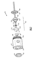
- FIG. 2 shows one example of a wheel end assembly 20 as used with the tire inflation system 10.
- the axle 12 includes an axle housing 22 within an internal cavity 24 that directs pressurized air to an axle outlet 26 at an end face 28 of the axle housing.
- the wheel end assembly 20 includes a hub cap 30 that is mounted for rotation with the tire 14 about an axis A.
- a connector 32 is used to fluidly connect the non-rotating axle housing 22 to the rotating hub cap 30.
- the connector 32 provides a sealed interface that allows pressurized air to be communicated from a non-rotating component to a rotating component without leaking.
- the connector 32 includes a tube 34 that has a first tube end 36 and a second tube end 38.
- the tube is made from a stainless steel material; however, other materials could also be used.
- the first tube end 36 comprises an outboard end and the second tube end 38 comprises an inboard end.
- the term "outboard” refers to a direction that faces away from a vehicle center and the term “inboard” refers to a direction that faces toward a vehicle center.
- the first tube end 36 is supported within a connector body 40 and the second tube end 38 is supported within a seal assembly 42 associated with the axle housing 22.
- the tube 34 rotates within the seal assembly 42.
- First 44a and second 44b hose connections are coupled to the connector body 40 to communicate the pressurized air from the connector 32 to the tires 14 as known.
- each wheel end assembly 20 includes a pair of tires, one inboard tire and one outboard tire, and the first hose 44a supplies air to one of the tires and the second hose 44b supplies air to the other tire.
- the connector body 40 includes an outer peripheral surface 50 that includes a pair of air outlets 52 that are coupled to the first 44a and second 44b hoses.
- the connector body 40 has an outboard end face 54 and an inboard end face 56.
- the air outlets 52 are located between the inboard 56 and outboard 54 end faces.
- the body 40 includes an air inlet 58 that is at the inboard end face 56.
- the outer peripheral surface 50 has a threaded portion 50a about an inboard end of the body 40 such that the connector 32 can be threadably attached to the hub cap 30.
- Other attachment methods could also be used to secure the connector 32 to the hub cap 30.
- the body 40 includes an internal cavity 60 that interconnects the air inlet 58 at one end to the air outlets 52.
- a seal assembly 62 is at least partially received within the internal cavity 60.
- a retainer 64 is positioned at the air inlet 58 and is pressed into internal cavity 60 at the inboard end face 56 to securely hold the seal assembly 62 within the internal cavity 60.
- a second seal 66 is positioned on an outboard side of the seal assembly 62 at an interface that fluidly connects to the air outlets 52.
- the first tube end 36 is supported within the seal assembly 62 such that the seal assembly 62 and tube 34 can rotate relative to each other.
- the seal assembly 62 includes a curved outer surface 68 that abuts directly against a curved surface portion 70 formed within the internal cavity 60.
- the curved outer surface 68 comprises a spherical surface. This seal contact configuration allows the seal assembly 62 to rotate within the body 40 as needed to accommodate tolerance stack-up issues that can arise once the various components are assembled together.
- the curved outer surface 68 comprises a first surface portion that directly engages the body 40.
- the seal assembly 62 also includes a curved surface portion 72 that directly engages a corresponding curved surface 74 formed on an inboard end of the retainer 64.
- the retainer 64 is held fixed to the body 40 by a press-fit or other type of connection interface.
- the curved surface portion 72 allows the seal assembly to rotate relative to the retainer 64 as needed.
- this ball and socket type connection interface between the connector body 40 and the seal assembly 62 provides another degree of freedom of movement to accommodate a wide range of tolerance stack-ups such as runout between the hub and axle, for example.
- the body 40 also includes an internal lubrication chamber 80 that is positioned outboard of the internal cavity 60.
- the lubrication chamber 80 is fluidly separated from the air outlets 52, the internal cavity 60, and the air inlet 58.
- At least one opening 82 is formed within the outboard end face 54 of the connector body 40. In the example shown, the at least one opening 82 comprises an enlarged central opening.
- a plug 84 is detachably secured to the body 40 to allow lubricant to be added to the lubrication chamber 80 as needed.
- the plug 84 is formed from a resilient material that allows the plug 84 to be repeatedly attached and detached from the connector 32 in a simple manner.
- a flange portion 86 is formed about the opening 82 inside the lubrication chamber 80.
- the plug 84 includes an internal lip 88 that snaps over this flange portion 86 to hold the plug 84 securely in place.
- a plurality of vent holes 90 extend from the internal lubrication chamber 80 to the outboard end face 54 of the body 40.
- the vent holes 90 are circumferentially spaced apart from each other about the central opening 82.
- the plug 84 includes a flexible flange 92 that is formed about an outer peripheral surface of the plug 84, and which is positioned to overlap the vent holes 90.
- the flexible flange 92 comprises a moveable flap that covers the vent holes 90 to prevent lubrication from exiting the chamber 80.
- the vent holes 90 operate to prevent the lubrication chamber 80 from being pressurized.
- the increased air pressure acts to move the flange 92 out of contact with the outboard end face 54 of the body as indicated by arrows 94. This allows the pressurized air to escape to atmosphere. Once the pressure within the chamber 80 falls below the predetermined limit, the flange 92 returns to its original position to cover the vent holes 90.
- the body 40 also includes a plurality of bores 96 ( Figure 6 ) that extend from the inboard end face 56 to the internal lubrication chamber 80.
- the bores 96 are circumferentially spaced apart from each other about the air inlet 58.
- the bores 96 are spaced such that they do not intersect the air outlets 52.
- the retainer 64 includes an enlarged flange portion 98 formed about an outer peripheral surface that at least partially overlaps the bores 96.
- An outboard surface of the flange portion 98 is axially spaced from the inboard end face 56 of the body.
- the bores 96 cooperate with the flange portion 98 to create a labyrinth design to mitigate loss of lubrication.
- the bores 96 also allow hub lubrication fill to be performed in a center of the wheel unit.
- the seal assembly 62 can comprise a completely spherical element such as that shown in Figures 3-6 or other seal configurations can also be used.
- the seal assembly 62 of Figures 3-6 comprises a single element 62a with an internal bore 62b extending therethrough to receive the tube 34.
- An abutment 62c prevents the tube 34 from extending into the second seal 66.
- the second seal 66 comprises a cup-shaped element with cross-holes that fluidly connect to the air outlets 52. Air flows through the tube 34, into an internal cavity of the second seal 66 and then exits the outlets 52.
- Figures 7-9 show another example of a seal assembly 62'.
- the body 40, second seal 66, retainer 64, and plug 84 are the same as that shown in Figures 3-6 .
- the seal assembly 62' in this example comprises a two-piece configuration with a first seal component 100 and a second seal component 102 that are secured together via a snap-fit or other attachment method.
- the first seal component 100 includes an abutment 104 that retains the tube 34 within a seal body such that the tube 34 cannot be axially disconnected from the seal body.
- a secondary seal 106 provides a sealed interface for the tube 34 within the seal assembly 62'.
- the first seal component 100 comprises a cup-shaped member with a spherical surface 108 that faces the air inlet 58.
- a cylindrical portion 110 extends axially outwardly from a bottom of a cup-shaped cavity toward the second seal component, i.e. extends in an outboard direction.
- the cylindrical portion 110 defines an internal bore 112 that receives the tube 34.
- the second seal component 102 comprises a cup-shaped member with a spherical portion 114 that abuts against the curved surface portion 70 formed within the internal cavity 60.
- a cylindrical portion or hub portion 116 extends axially outwardly from a bottom of a cup-shaped cavity toward the first seal component 100, i.e. extends in an inboard direction.
- the hub portion 116 includes an internal bore 118 that is open to an interior of the tube 34. Air exits the tube 34, passes through the bore 118 and enters the cup-shaped cavity of the seal 66.
- the outboard first tube end 36 of the tube 34 comprises a flared tube end 120.
- the cylindrical portion 110 of the first seal component 100 terminates at the abutment 104.
- the flared tube end 120 engages the abutment 104 to prevent the tube 34 from being axially withdrawn from the seal body.
- the hub portion 116 seats the secondary seal 106 to provide sealing engagement between the flared tube end 120 and the second seal component 102.
- the first and second seal components 100, 102 each include a truncated portion 122, i.e. a cylindrical portion, which extends toward each other.
- the truncated portion 122 terminates at an abutting contact surface 124 between the two seal components 100, 102.
- This truncation removes material, which reduces cost.
- the ball and socket joint described above overcomes the weaknesses of a traditional thru-tee connection.
- the ball and socket design allows flexibility to accommodate runout between the hub and the axle.
- the tube inside the ball may either rotate within the ball within the seal, or can run on the seal in the axle mounted receiving tube.
- the vent holes that are partially covered create a labyrinth design to mitigate oil loss. Breather holes perform double duty to allow hub oil filling to be performed in a center of the unit.
Abstract
Description
- The subject invention relates to a seal assembly for a tire inflation system.
- Over time, tires inherently loose air pressure through permeation and leaks. Tire inflation systems monitor this pressure loss and act to supply air to under-inflated tires as needed. Once the tires are inflated to a proper pressure level, the tire inflation system continues to monitor and maintain proper tire pressure to maximize the life of the tire.
- In one known configuration, the tire inflation system communicates compressed air through a non-rotating component, such as an axle housing for example, into a rotating component, which is connected to the tire. Typically, the rotating component comprises a thru-tee connector that is attached to a hub cap. Difficulties arise when communicating pressurized air through this type of rotating connection.
- In a first aspect of the invention there is provided a connector for a tire inflation system includes a body with an air inlet receiving pressurized air from an air supply and an air outlet to communicate the pressurized air to at least one tire. The body is to be connected to a rotating wheel component and includes an internal cavity connecting the air inlet to the air outlet. A seal assembly is positioned within the internal cavity. A tube has a first end supported by the seal assembly and a second end that is to be coupled to a non-rotating axle component. The seal assembly and tube are rotatable relative to each other and seal assembly is rotatable relative to the body. The tube communicates pressurized air from the non-rotating axle component to the air inlet to inflate the tire as needed.
- In a second aspect of the invention there is provided a connector for a tire inflation system comprising:
- a body including an air inlet receiving pressurized air from an air supply and an air outlet to communicate the pressurized air to at least one tire, said body including an internal cavity connecting said air inlet to said air outlet, said body adapted to be connected to a rotating wheel component;
- a seal assembly at least partially received within said internal cavity; and
- a tube having a first end supported by said seal assembly and a second end adapted for connection to a non-rotating axle component, said tube communicating pressurized air from the non-rotating axle component to said air inlet, and wherein said seal assembly and said tube are rotatable relative to each other and said seal assembly is rotatable relative to said body.
- In one example, the connector includes an internal lubrication compartment positioned outboard of the internal cavity. The connector includes an outboard end face having at least one opening to supply lubrication to the internal lubrication compartment. The opening receives a detachable plug to hold the lubrication within the internal lubrication compartment.
- In one example, the connector includes a plurality of vent holes extending from the internal lubrication cavity to the outboard end face. The vent holes are circumferentially spaced apart from each other about the opening. The plug includes a flexible flange formed about an outer peripheral surface of the plug. The flexible flange portion overlaps the plurality of vent holes.
- In one example, the seal assembly comprises a seal body including at least one curved surface portion that abuts against a corresponding curved surface portion formed within the internal cavity of the connector.
- In one example, the seal body comprises first and second pieces that are secured together. One of the first and second pieces includes an abutment that retains the tube within the seal body such that the tube cannot be axially disconnected from the seal body. A secondary seal can be mounted within the first and second pieces to seal the tube within the seal body.
- In a third aspect of the present invention there is provided a tire inflation system comprising a connector according to the first or second aspect.
- The tire inflation system may further comprise a non-rotating axle component; a hub cap mounted for rotation relative to said non-rotating axle component about an axis; and the connector may be connected to said hub cap.
- In a fourth aspect there is provided a tire inflation system comprising:
- a non-rotating axle component;
- a hub cap mounted for rotation relative to said non-rotating axle component about an axis;
- a connector connected to said hub cap, said connector including an air inlet, an air outlet, and an internal cavity interconnecting said air inlet and said air outlet to communicate pressurized air to at least one tire via said air outlet;
- a seal assembly at least partially received within said internal cavity; and
- a tube having a first end supported by said seal assembly and a second end adapted for connection to said non-rotating axle component, said non-rotating axle component being coupled to an air supply, and wherein said tube communicates pressurized air from said non-rotating axle component to said air inlet, and wherein said seal assembly and said tube are rotatable relative to each other and said seal assembly is rotatable relative to said connector.
- The following features are optional features of the third or fourth aspect.
- The connector may include an internal lubrication compartment positioned outboard of said internal cavity. The connector may include an outboard end face having at least one opening to supply lubrication to said internal lubrication compartment. The at least one opening may receive a detachable plug to hold the lubrication within said internal lubrication compartment.
- The connector may include a plurality of vent holes extending from said internal lubrication cavity to said outboard end face. The vent holes may be circumferentially spaced apart from each other about said at least one opening. The plug may include a flexible flange formed about an outer peripheral surface of said plug. The flexible flange portion may overlap said plurality of vent holes.
- The connector may include an inboard end face that defines said air inlet. The connector may comprise a plurality of bores formed within said connector and extending from said inboard end face to said internal lubrication compartment to allow lubrication to be directed into said internal lubrication compartment. The plurality of bores may be circumferentially spaced apart from each other about said air inlet. The container may include a retainer to retain said seal assembly within said internal cavity. The retainer may include an enlarged flange portion formed about an outer periphery of said retainer. The enlarged flange portion may at least partially overlap said plurality of bores.
- The seal assembly may include at least one curved surface portion that abuts against a corresponding curved surface portion formed within said internal cavity. The seal body may comprise first and second pieces that are secured together. At least one of said first and second pieces may include an abutment that retains said tube within said seal body such that said tube cannot be axially disconnected from said seal body. These and other features of the present invention can be best understood from the following specification and drawings, the following of which is a brief description.
-
-
Figure 1 is a schematic representation of a tire inflation system. -
Figure 2 is a schematic view, in partial cross-section, of one example of a wheel end assembly as used with the tire inflation system. -
Figure 3 is a perspective view from an inboard end of a connector as used in the tire inflation system. -
Figure 4 is a perspective view of the connector ofFigure 3 from an outboard end. -
Figure 5 is a cross-section of the connector ofFigure 3 taken along lines 5-5 as indicated inFigure 3 . -
Figure 6 is a cross-section of the connector ofFigure 3 taken along lines 6-6 as shown inFigure 4 . -
Figure 7 is an exploded view facing an outboard end of a connector assembly showing one example of a seal. -
Figure 8 is an exploded view of the connector ofFigure 7 facing an inboard direction. -
Figure 9 is a cross-sectional view of the connector ofFigure 7 . -
Figure 1 shows atire inflation system 10 that supplies pressurized air to anaxle 12, which in turn supplies pressurized air to one ormore tires 14 as needed to maintain a desired tire pressure. Theaxle 12 receives pressurized air from an air supply 16. The subjecttire inflation system 10 can be used with any type of axle such as a non-drive axle, drive axle, steer-axle, non-steer axle, etc., for example. The air supply 16 can be a dedicated air supply or can comprise an existing air supply already utilized on the vehicle, such as an air supply for vehicle brakes for example. - The
tire inflation system 10 includes acontrol 18 that monitors tire pressure and acts to supply air to thetires 14 when thetires 14 become under-inflated, i.e. when tire pressures fall below a desired pressure level. Thecontrol 18 includes appropriate structures and program algorithms that are used to determine when air is to be supplied to thetires 14 and which are used to control the amount of air supplied as known. Thecontrol 18 can be automatically activated via an electronic control unit or other similar device to control the amount of air supplied, or thecontrol 18 can be manually actuated by a vehicle operator. Thecontrol 18 can include various valves, sensors, pressure regulators, etc. as known to control distribution of the air from the air supply 16. Thecontrol 18 is also configured to stop supplying air to atire 14 if pressure falls below a certain level to prevent the air source 16 from being depleted of air, such as when atire 14 has experienced a blow-out for example. - The
control 18 supplies air to a non-rotating component, in this example theaxle 12, which includes passages that direct the pressurized air toward the rotatingtire 14. -
Figure 2 shows one example of awheel end assembly 20 as used with thetire inflation system 10. Theaxle 12 includes anaxle housing 22 within aninternal cavity 24 that directs pressurized air to anaxle outlet 26 at anend face 28 of the axle housing. - The
wheel end assembly 20 includes ahub cap 30 that is mounted for rotation with thetire 14 about an axis A. Aconnector 32 is used to fluidly connect thenon-rotating axle housing 22 to therotating hub cap 30. Theconnector 32 provides a sealed interface that allows pressurized air to be communicated from a non-rotating component to a rotating component without leaking. - The
connector 32 includes atube 34 that has afirst tube end 36 and asecond tube end 38. In one example, the tube is made from a stainless steel material; however, other materials could also be used. Thefirst tube end 36 comprises an outboard end and thesecond tube end 38 comprises an inboard end. The term "outboard" refers to a direction that faces away from a vehicle center and the term "inboard" refers to a direction that faces toward a vehicle center. Thefirst tube end 36 is supported within aconnector body 40 and thesecond tube end 38 is supported within aseal assembly 42 associated with theaxle housing 22. Thetube 34 rotates within theseal assembly 42. First 44a and second 44b hose connections are coupled to theconnector body 40 to communicate the pressurized air from theconnector 32 to thetires 14 as known. Typically, eachwheel end assembly 20 includes a pair of tires, one inboard tire and
one outboard tire, and thefirst hose 44a supplies air to one of the tires and thesecond hose 44b supplies air to the other tire. - As shown in
Figures 3-6 , theconnector body 40 includes an outerperipheral surface 50 that includes a pair ofair outlets 52 that are coupled to the first 44a and second 44b hoses. Theconnector body 40 has anoutboard end face 54 and aninboard end face 56. Theair outlets 52 are located between the inboard 56 and outboard 54 end faces. Thebody 40 includes anair inlet 58 that is at theinboard end face 56. - In one example, the outer
peripheral surface 50 has a threadedportion 50a about an inboard end of thebody 40 such that theconnector 32 can be threadably attached to thehub cap 30. Other attachment methods could also be used to secure theconnector 32 to thehub cap 30. - As shown in
Figure 5 , thebody 40 includes aninternal cavity 60 that interconnects theair inlet 58 at one end to theair outlets 52. Aseal assembly 62 is at least partially received within theinternal cavity 60. Aretainer 64 is positioned at theair inlet 58 and is pressed intointernal cavity 60 at theinboard end face 56 to securely hold theseal assembly 62 within theinternal cavity 60. Asecond seal 66 is positioned on an outboard side of theseal assembly 62 at an interface that fluidly connects to theair outlets 52. - The
first tube end 36 is supported within theseal assembly 62 such that theseal assembly 62 andtube 34 can rotate relative to each other. Theseal assembly 62 includes a curvedouter surface 68 that abuts directly against acurved surface portion 70 formed within theinternal cavity 60. In one example, the curvedouter surface 68 comprises a spherical surface. This seal contact configuration allows theseal assembly 62 to rotate within thebody 40 as needed to accommodate tolerance stack-up issues that can arise once the various components are assembled together. - The curved
outer surface 68 comprises a first surface portion that directly engages thebody 40. Theseal assembly 62 also includes acurved surface portion 72 that directly engages a correspondingcurved surface 74 formed on an inboard end of theretainer 64. Theretainer 64 is held fixed to thebody 40 by a press-fit or other type of connection interface. Thecurved surface portion 72 allows the seal assembly to rotate relative to theretainer 64 as needed. As such, this ball and socket type connection interface between theconnector body 40 and theseal assembly 62 provides another degree of freedom of movement to accommodate a wide range of tolerance stack-ups such as runout between the hub and axle, for example. - The
body 40 also includes aninternal lubrication chamber 80 that is positioned outboard of theinternal cavity 60. Thelubrication chamber 80 is fluidly separated from theair outlets 52, theinternal cavity 60, and theair inlet 58. At least oneopening 82 is formed within the outboard end face 54 of theconnector body 40. In the example shown, the at least oneopening 82 comprises an enlarged central opening. - A
plug 84 is detachably secured to thebody 40 to allow lubricant to be added to thelubrication chamber 80 as needed. Theplug 84 is formed from a resilient material that allows theplug 84 to be repeatedly attached and detached from theconnector 32 in a simple manner. Aflange portion 86 is formed about theopening 82 inside thelubrication chamber 80. Theplug 84 includes aninternal lip 88 that snaps over thisflange portion 86 to hold theplug 84 securely in place. - A plurality of vent holes 90 extend from the
internal lubrication chamber 80 to the outboard end face 54 of thebody 40. The vent holes 90 are circumferentially spaced apart from each other about thecentral opening 82. Theplug 84 includes aflexible flange 92 that is formed about an outer peripheral surface of theplug 84, and which is positioned to overlap the vent holes 90. As such, theflexible flange 92 comprises a moveable flap that covers the vent holes 90 to prevent lubrication from exiting thechamber 80. The vent holes 90 operate to prevent thelubrication chamber 80 from being pressurized. If pressure within thelubrication chamber 80 exceeds a predetermined limit, the increased air pressure acts to move theflange 92 out of contact with the outboard end face 54 of the body as indicated byarrows 94. This allows the pressurized air to escape to atmosphere. Once the pressure within thechamber 80 falls below the predetermined limit, theflange 92 returns to its original position to cover the vent holes 90. - The
body 40 also includes a plurality of bores 96 (Figure 6 ) that extend from theinboard end face 56 to theinternal lubrication chamber 80. Thebores 96 are circumferentially spaced apart from each other about theair inlet 58. Thebores 96 are spaced such that they do not intersect theair outlets 52. Theretainer 64 includes anenlarged flange portion 98 formed about an outer peripheral surface that at least partially overlaps thebores 96. An outboard surface of theflange portion 98 is axially spaced from the inboard end face 56 of the body. In the event of a seal failure, thebores 96 cooperate with theflange portion 98 to create a labyrinth design to mitigate loss of lubrication. Thebores 96 also allow hub lubrication fill to be performed in a center of the wheel unit. - The
seal assembly 62 can comprise a completely spherical element such as that shown inFigures 3-6 or other seal configurations can also be used. Theseal assembly 62 ofFigures 3-6 comprises asingle element 62a with aninternal bore 62b extending therethrough to receive thetube 34. Anabutment 62c prevents thetube 34 from extending into thesecond seal 66. Thesecond seal 66 comprises a cup-shaped element with cross-holes that fluidly connect to theair outlets 52. Air flows through thetube 34, into an internal cavity of thesecond seal 66 and then exits theoutlets 52.Figures 7-9 show another example of a seal assembly 62'. Thebody 40,second seal 66,retainer 64, and plug 84 are the same as that shown inFigures 3-6 . - The seal assembly 62' in this example comprises a two-piece configuration with a
first seal component 100 and asecond seal component 102 that are secured together via a snap-fit or other attachment method. Thefirst seal component 100 includes anabutment 104 that retains thetube 34 within a seal body such that thetube 34 cannot be axially disconnected from the seal body. Asecondary seal 106 provides a sealed interface for thetube 34 within the seal assembly 62'. - The
first seal component 100 comprises a cup-shaped member with aspherical surface 108 that faces theair inlet 58. Acylindrical portion 110 extends axially outwardly from a bottom of a cup-shaped cavity toward the second seal component, i.e. extends in an outboard direction. Thecylindrical portion 110 defines aninternal bore 112 that receives thetube 34. - The
second seal component 102 comprises a cup-shaped member with aspherical portion 114 that abuts against thecurved surface portion 70 formed within theinternal cavity 60. A cylindrical portion orhub portion 116 extends axially outwardly from a bottom of a cup-shaped cavity toward thefirst seal component 100, i.e. extends in an inboard direction. Thehub portion 116 includes aninternal bore 118 that is open to an interior of thetube 34. Air exits thetube 34, passes through thebore 118 and enters the cup-shaped cavity of theseal 66. - In this example, the outboard
first tube end 36 of thetube 34 comprises a flaredtube end 120. Thecylindrical portion 110 of thefirst seal component 100 terminates at theabutment 104. The flaredtube end 120 engages theabutment 104 to prevent thetube 34 from being axially withdrawn from the seal body. Thehub portion 116 seats thesecondary seal 106 to provide sealing engagement between the flaredtube end 120 and thesecond seal component 102. - In this example, the first and
second seal components truncated portion 122, i.e. a cylindrical portion, which extends toward each other. Thetruncated portion 122 terminates at an abutting contact surface 124 between the twoseal components - Although a preferred embodiment of this invention has been disclosed, a worker of ordinary skill in this art would recognize that certain modifications would come within the scope of this invention. For that reason, the following claims should be studied to determine the true scope and content of this invention.
Claims (15)
- A connector for a tire inflation system comprising:a body including an air inlet receiving pressurized air from an air supply and an air outlet to communicate the pressurized air to at least one tire, said body including an internal cavity connecting said air inlet to said air outlet, said body adapted to be connected to a rotating wheel component;a seal assembly at least partially received within said internal cavity; anda tube having a first end supported by said seal assembly and a second end adapted for connection to a non-rotating axle component, said tube communicating pressurized air from the non-rotating axle component to said air inlet, and wherein said seal assembly and said tube are rotatable relative to each other and said seal assembly is rotatable relative to said body.
- The connector according to claim 1 wherein said seal assembly comprises a seal body including at least one curved surface portion that abuts against a corresponding curved surface portion formed within said internal cavity.
- The connector according to claim 2 wherein said seal body comprises a spherical component including an internal bore that receives said first end of said tube.
- The connector according to claim 2 or 3 wherein said seal body comprises first and second pieces that are secured together, and wherein at least one of said first and second pieces includes an abutment that retains said tube within said seal body such that said tube cannot be axially disconnected from said seal body, preferably the connector includes a secondary seal to provide a sealed interface between said tube and one of said first and said second pieces.
- The connector according to claim 4 wherein said first piece comprises a cup-shaped member with a first spherical portion that abuts against said curved surface portion formed within said internal cavity and a first cylindrical portion that extends from said first spherical portion toward said second piece, and wherein said second piece comprises a cup-shaped member with a second spherical surface facing said air inlet and a second cylindrical portion that extends from said second spherical portion to abut against said first cylindrical portion of said first piece.
- The connector according to claim 5 wherein said second piece includes a tubular extension extending from an inner surface of said second spherical portion toward an inner surface of said first spherical portion, said tubular extension receiving said first end of said tube.
- The connector according to claim 6 wherein said first end of said tube comprises a flared tube end and wherein said tubular extension terminates at said abutment, said flared tube end engaging said abutment to prevent said tube from being axially withdrawn from said seal body, preferably wherein said first piece includes a hub portion extending outwardly from said internal surface of said first spherical portion, said hub portion seating said secondary seal to provide sealing engagement between said flared tube end and said first piece.
- The connector according to claim 2 or 3 wherein said seal body includes at least one additional curved surface portion and including a retainer having a curved abutment surface that engages said additional curved surface portion, said retainer being coupled to said body to retain said seal body within said internal cavity.
- The connector according to claim 8 wherein said seal body comprises a first seal body and wherein said seal assembly includes a second seal body that engages said at least one curved surface portion of said first seal body, said at least one curved surface portion including an opening that directs pressurized air from said tube into an internal cavity of said second seal body, preferably wherein said second seal body comprises a cup-shaped member with at least one side wall opening to communicate pressurized air to said air outlet of said body.
- The connector according to any one of the previous claims wherein said body includes an internal lubrication compartment positioned outboard of said internal cavity, said body including an outboard end face having a central opening to supply lubrication to said internal lubrication compartment, and wherein said central opening receives a detachable plug to hold the lubrication within said internal lubrication compartment.
- The connector according to claim 10 including a plurality of vent holes extending from said internal lubrication cavity to said outboard end face, said vent holes being circumferentially spaced apart from each other about said central opening, and wherein said plug includes a flexible flange formed about an outer peripheral surface of said plug, said flexible flange portion overlapping said plurality of vent holes.
- The connector according to claim 10 or 11 wherein said body includes an inboard end face that defines said air inlet, and including a plurality of bores formed within said body and extending from said inboard end face to said internal lubrication compartment to allow lubrication to be directed into said internal lubrication compartment, preferably wherein said plurality of bores are circumferentially spaced apart from each other about said air inlet, and including a retainer to retain said seal body within said internal cavity, said retainer including an enlarged flange portion formed about an outer peripheral surface that at least partially overlaps said plurality of bores.
- A tire inflation system comprising:a non-rotating axle component;a hub cap mounted for rotation relative to said non-rotating axle component about an axis;a connector connected to said hub cap, said connector including an air inlet, an air outlet, and an internal cavity interconnecting said air inlet and said air outlet to communicate pressurized air to at least one tire via said air outlet;
a seal assembly at least partially received within said internal cavity; and
a tube having a first end supported by said seal assembly and a second end adapted for connection to said non-rotating axle component, said non-rotating axle component being coupled to an air supply, and wherein said tube communicates pressurized air from said non-rotating axle component to said air inlet, and wherein said seal assembly and said tube are rotatable relative to each other and said seal assembly is rotatable relative to said connector. - The tire inflation system according to claim 13 wherein said connector includes an internal lubrication compartment positioned outboard of said internal cavity, said connector including an outboard end face having at least one opening to supply lubrication to said internal lubrication compartment, and wherein said at least one opening receives a detachable plug to hold the lubrication within said internal lubrication compartment, preferably wherein said connector includes a plurality of vent holes extending from said internal lubrication cavity to said outboard end face, said vent holes being circumferentially spaced apart from each other about said at least one opening, and wherein said plug includes a flexible flange formed about an outer peripheral surface of said plug, said flexible flange portion overlapping said plurality of vent holes, and preferably wherein said connector includes an inboard end face that defines said air inlet, and including a plurality of bores formed within said connector and extending from said inboard end face to said internal lubrication compartment to allow lubrication to be directed into said internal lubrication compartment, and wherein said plurality of bores are circumferentially spaced apart from each other about said air inlet, and including a retainer to retain said seal assembly within said internal cavity, said retainer including an enlarged flange portion formed about an outer periphery of said retainer, said enlarged flange portion at least partially overlapping said plurality of bores.
- The tire inflation system according to claim 13 or 14 wherein said seal assembly comprises a seal body including at least one curved surface portion that abuts against a corresponding curved surface portion formed within said internal cavity, and wherein said seal body comprises first and second pieces that are secured together, and wherein at least one of said first and second pieces includes an abutment that retains said tube within said seal body such that said tube cannot be axially disconnected from said seal body.
Applications Claiming Priority (1)
| Application Number | Priority Date | Filing Date | Title |
|---|---|---|---|
| US13/160,570 US8746305B2 (en) | 2011-06-15 | 2011-06-15 | Rotating seal assembly for tire inflation system |
Publications (2)
| Publication Number | Publication Date |
|---|---|
| EP2535208A1 true EP2535208A1 (en) | 2012-12-19 |
| EP2535208B1 EP2535208B1 (en) | 2016-04-06 |
Family
ID=46275721
Family Applications (1)
| Application Number | Title | Priority Date | Filing Date |
|---|---|---|---|
| EP12172083.3A Not-in-force EP2535208B1 (en) | 2011-06-15 | 2012-06-14 | Rotating seal assembly for tire inflation system |
Country Status (2)
| Country | Link |
|---|---|
| US (1) | US8746305B2 (en) |
| EP (1) | EP2535208B1 (en) |
Cited By (2)
| Publication number | Priority date | Publication date | Assignee | Title |
|---|---|---|---|---|
| EP3068639A4 (en) * | 2013-11-11 | 2017-06-21 | Equalaire Systems, Inc. | Rotary union for tire inflation system |
| US11685201B2 (en) | 2016-10-19 | 2023-06-27 | Pressure Systems International, Llc | Inflation manifold |
Families Citing this family (16)
| Publication number | Priority date | Publication date | Assignee | Title |
|---|---|---|---|---|
| WO2014071220A2 (en) | 2012-11-01 | 2014-05-08 | FlowBelow Aero, Inc. | Aerodynamic system and adjustable fairings |
| GB2516697B (en) * | 2013-07-30 | 2016-06-29 | Jaguar Land Rover Ltd | Vehicle Axle Assembly |
| US10562357B2 (en) | 2015-06-12 | 2020-02-18 | Dana Heavy Vehicle Systems Group, Llc | Rotary joint air collector ring and the tire inflation system made therewith |
| US10556469B2 (en) | 2015-09-17 | 2020-02-11 | Dana Heavy Vehicle Systems Group, Llc | Hub cap assembly and a wheel end assembly for a tire inflation system |
| JP6657520B2 (en) * | 2016-02-03 | 2020-03-04 | 株式会社神戸製鋼所 | Tire air filling mechanism and tire air filling method of tire testing device |
| US11292299B2 (en) * | 2016-08-26 | 2022-04-05 | IP Holdings One, LLC | Apparatus for delivering air through trailer axle system |
| EP3535145B1 (en) | 2016-11-04 | 2024-05-15 | Flowbelow Aero, Inc. | Chassis mounted energy extraction and delivery system |
| US10654529B2 (en) | 2017-06-24 | 2020-05-19 | FlowBelow Aero, Inc. | Aerodynamic systems and fairings with fairing caps |
| EP3652023A4 (en) | 2017-07-12 | 2021-04-07 | Flowbelow Aero, Inc. | Aerodynamic toolbox assembly |
| US10882571B2 (en) | 2017-07-30 | 2021-01-05 | FlowBelow Aero, Inc. | Rotatable aerodynamic fairing system |
| US11454322B2 (en) | 2019-06-04 | 2022-09-27 | Fairfield Manufacturing Company, Inc. | Rotary pneumatic seal for a central tire inflation system |
| MX2022001265A (en) * | 2019-08-12 | 2022-02-22 | Equalaire Systems Inc | Adjustable position rotary union. |
| US11767064B2 (en) | 2021-01-12 | 2023-09-26 | FlowBelow Aero, Inc. | Spring-biased mud flap hanger with improved pivoting motion guidance |
| US11845347B2 (en) | 2021-05-12 | 2023-12-19 | David Alan Copeland | Precision charging control of an untethered vehicle with a modular vehicle charging roadway |
| US11376898B1 (en) * | 2021-07-19 | 2022-07-05 | Globetech Manufacturing, Inc. | Air inflation system |
| AU2021290374A1 (en) * | 2021-12-24 | 2023-07-13 | Chets Professional Services Pty. Ltd. | Improved mechanism of transferring air/ liquid/ gas of stationary component to second rotating component. |
Citations (5)
| Publication number | Priority date | Publication date | Assignee | Title |
|---|---|---|---|---|
| US1794900A (en) * | 1929-05-18 | 1931-03-03 | Rutherford H Hutchinson | Tire-inflating mechanism |
| US3331638A (en) * | 1965-09-15 | 1967-07-18 | Int Harvester Co | Hub cap with fill plug |
| DE2540240A1 (en) * | 1975-09-10 | 1977-03-24 | Rudolf F Ing Grad Garbaty | Pneumatic coupling for monitoring tyre pressure - has resilient ring between parts, pressurized by liquid, also O rings |
| US5584949A (en) * | 1994-05-06 | 1996-12-17 | Ingram; Anthony L. | Air inflation system for trailer axles |
| US20040000364A1 (en) * | 2002-07-01 | 2004-01-01 | Equalaire Systems, Inc. | Rotary air connection with bearing for tire inflation system |
Family Cites Families (27)
| Publication number | Priority date | Publication date | Assignee | Title |
|---|---|---|---|---|
| US4335283A (en) | 1979-12-05 | 1982-06-15 | Eaton Corporation | Temperature compensated fill valve/pressure switch |
| US4434833A (en) | 1982-04-21 | 1984-03-06 | Eaton Corporation | Axle wheel end assembly |
| US4724879A (en) | 1984-06-04 | 1988-02-16 | Eaton Corporation | Central tire inflation system |
| US4895199A (en) | 1986-07-31 | 1990-01-23 | Paccar Inc | Tire inflation and deflation valve |
| US4844138A (en) * | 1986-09-01 | 1989-07-04 | Kabushiki Kaisha Tokai Rika Denki Seisakusho | Automobile tire pneumatic pressure controlling apparatus |
| US4782878A (en) | 1986-12-18 | 1988-11-08 | Tire Inflation Systems, Corp. | Tire inflating and deflating system and apparatus |
| US4924926A (en) | 1988-08-15 | 1990-05-15 | Eaton Corporation | Central tire inflation system |
| US4883106A (en) | 1989-01-19 | 1989-11-28 | Eaton Corporation | Rotary wheel-end assembly for tire inflation system |
| US4938272A (en) | 1989-01-26 | 1990-07-03 | General Motors Corporation | Valve actuator for tire pressure management |
| ES2082030T3 (en) | 1990-05-17 | 1996-03-16 | Equalaire Systems Inc | AIR CONTROL SYSTEM FOR VEHICLE TIRES. |
| US5253687A (en) | 1991-09-03 | 1993-10-19 | Eaton Corporation | Vehicle central tire inflation system |
| US5377736A (en) * | 1993-11-18 | 1995-01-03 | Marks-Rms, Inc. | Driven axle vehicle inflation system |
| US5769979A (en) | 1996-08-30 | 1998-06-23 | Equalaire Systems, Inc. | Rotary air connection for tire inflation system |
| US6105645A (en) * | 1998-05-14 | 2000-08-22 | Ingram; Anthony L. | Rotary union assembly for use in air pressure inflation systems for tractor trailer tires |
| US6250327B1 (en) | 1999-02-25 | 2001-06-26 | Dana Corporation | Fluid flow valve with variable flow rate |
| US6131631A (en) | 1999-05-10 | 2000-10-17 | Equalaire Systems, Inc. | Press plug support for tire inflation system |
| WO2001002196A1 (en) | 1999-07-02 | 2001-01-11 | Pressure Guard, Inc. | On-axle tire inflation system |
| US6394159B1 (en) | 2001-01-26 | 2002-05-28 | Meritor Heavy Vehicle Technology, Llc | Hub cap filter for tire inflation system |
| US6474383B1 (en) | 2001-05-31 | 2002-11-05 | Hutchinson, S.A. | Automotive wheel with improved inflation system |
| US6604414B1 (en) | 2001-12-04 | 2003-08-12 | Dana Corporation | Supply and tire pressure sensing apparatus and method |
| US6880598B2 (en) | 2002-09-06 | 2005-04-19 | Eaton Corporation | Check valve for tire inflation system |
| WO2004080729A2 (en) * | 2003-03-06 | 2004-09-23 | Nelson Christopher A | Central tire inflation system rotary air union |
| US7185688B2 (en) | 2004-01-27 | 2007-03-06 | Arvinmeritor Technology, Llc | Central tire inflation system for drive axle |
| US20050194079A1 (en) | 2004-03-08 | 2005-09-08 | Equalaire Systems, Inc. | Easy maintenance automatic tire inflation system |
| US8245746B2 (en) | 2004-07-21 | 2012-08-21 | Arvinmeritor Technology, Llc | Tire inflation system with pressure limiter |
| US7690412B1 (en) | 2008-11-04 | 2010-04-06 | Arvinmeritor Technology, Llc | Drive axle with air passage for tire inflation system |
| US7931061B2 (en) | 2008-12-15 | 2011-04-26 | Arvinmeritor Technology, Llc | Tire inflation system with integrated wheel seal |
-
2011
- 2011-06-15 US US13/160,570 patent/US8746305B2/en active Active
-
2012
- 2012-06-14 EP EP12172083.3A patent/EP2535208B1/en not_active Not-in-force
Patent Citations (5)
| Publication number | Priority date | Publication date | Assignee | Title |
|---|---|---|---|---|
| US1794900A (en) * | 1929-05-18 | 1931-03-03 | Rutherford H Hutchinson | Tire-inflating mechanism |
| US3331638A (en) * | 1965-09-15 | 1967-07-18 | Int Harvester Co | Hub cap with fill plug |
| DE2540240A1 (en) * | 1975-09-10 | 1977-03-24 | Rudolf F Ing Grad Garbaty | Pneumatic coupling for monitoring tyre pressure - has resilient ring between parts, pressurized by liquid, also O rings |
| US5584949A (en) * | 1994-05-06 | 1996-12-17 | Ingram; Anthony L. | Air inflation system for trailer axles |
| US20040000364A1 (en) * | 2002-07-01 | 2004-01-01 | Equalaire Systems, Inc. | Rotary air connection with bearing for tire inflation system |
Cited By (9)
| Publication number | Priority date | Publication date | Assignee | Title |
|---|---|---|---|---|
| EP3068639A4 (en) * | 2013-11-11 | 2017-06-21 | Equalaire Systems, Inc. | Rotary union for tire inflation system |
| AU2014346426B2 (en) * | 2013-11-11 | 2017-10-19 | Pressure Systems International, Llc | Rotary union for tire inflation system |
| EP3530494A1 (en) * | 2013-11-11 | 2019-08-28 | Equalaire Systems, Inc. | Rotary union for tire inflation system |
| AU2018200434B2 (en) * | 2013-11-11 | 2019-09-19 | Equalaire Systems, Inc. | Rotary union for tire inflation system |
| CN110561987A (en) * | 2013-11-11 | 2019-12-13 | 伊夸莱尔系统公司 | Vehicle tire inflation system |
| US10562356B2 (en) | 2013-11-11 | 2020-02-18 | Equalaire Systems, Inc. | Rotary union for tire inflation system |
| US11813898B2 (en) | 2013-11-11 | 2023-11-14 | Pressure Systems International, Llc | Rotary union for tire inflation system |
| US11685201B2 (en) | 2016-10-19 | 2023-06-27 | Pressure Systems International, Llc | Inflation manifold |
| US11738611B2 (en) | 2016-10-19 | 2023-08-29 | Pressure Systems International, Llc | Fluid conduits including pressure sensors |
Also Published As
| Publication number | Publication date |
|---|---|
| US8746305B2 (en) | 2014-06-10 |
| EP2535208B1 (en) | 2016-04-06 |
| US20120318422A1 (en) | 2012-12-20 |
Similar Documents
| Publication | Publication Date | Title |
|---|---|---|
| EP2535208B1 (en) | Rotating seal assembly for tire inflation system | |
| US7931061B2 (en) | Tire inflation system with integrated wheel seal | |
| US9908373B2 (en) | Rotary air connection with central valve for tire inflation system | |
| US7690412B1 (en) | Drive axle with air passage for tire inflation system | |
| CN103003074B (en) | Constant pressure air counterbalance tire inflation system | |
| EP2836376B1 (en) | Tire inflation system | |
| RU2460650C2 (en) | Integrated rotary unit and hub cap | |
| WO2001002196A1 (en) | On-axle tire inflation system | |
| US6260595B1 (en) | Unitized hub cap | |
| US10562357B2 (en) | Rotary joint air collector ring and the tire inflation system made therewith | |
| US20050161136A1 (en) | Central tire inflation system for drive axle | |
| EP2848435B1 (en) | Tire inflation system having a rotary coupling | |
| US11292299B2 (en) | Apparatus for delivering air through trailer axle system | |
| US20220324271A1 (en) | Multi-body hubcap for tire inflation systems | |
| AU2016226067B2 (en) | Steer axle tire inflation system | |
| US20220379668A1 (en) | Hub Covering for a Tyre Filling Device of a Vehicle | |
| US9989102B2 (en) | Vented gaiter | |
| CN114222673A (en) | Rotary union and hub cap with smooth bore | |
| WO2020215063A2 (en) | Tire pressure management system | |
| WO2000034092A2 (en) | Connection cartridge for air tanks | |
| US20230191853A1 (en) | Rotor with breather and anti-rotation arrangement for tire calibration arrangements | |
| CN116409095A (en) | Axle assembly having spindle plug and sleeve |
Legal Events
| Date | Code | Title | Description |
|---|---|---|---|
| PUAI | Public reference made under article 153(3) epc to a published international application that has entered the european phase |
Free format text: ORIGINAL CODE: 0009012 |
|
| AK | Designated contracting states |
Kind code of ref document: A1 Designated state(s): AL AT BE BG CH CY CZ DE DK EE ES FI FR GB GR HR HU IE IS IT LI LT LU LV MC MK MT NL NO PL PT RO RS SE SI SK SM TR |
|
| AX | Request for extension of the european patent |
Extension state: BA ME |
|
| 17P | Request for examination filed |
Effective date: 20130619 |
|
| RBV | Designated contracting states (corrected) |
Designated state(s): AL AT BE BG CH CY CZ DE DK EE ES FI FR GB GR HR HU IE IS IT LI LT LU LV MC MK MT NL NO PL PT RO RS SE SI SK SM TR |
|
| GRAP | Despatch of communication of intention to grant a patent |
Free format text: ORIGINAL CODE: EPIDOSNIGR1 |
|
| INTG | Intention to grant announced |
Effective date: 20151001 |
|
| GRAS | Grant fee paid |
Free format text: ORIGINAL CODE: EPIDOSNIGR3 |
|
| GRAA | (expected) grant |
Free format text: ORIGINAL CODE: 0009210 |
|
| AK | Designated contracting states |
Kind code of ref document: B1 Designated state(s): AL AT BE BG CH CY CZ DE DK EE ES FI FR GB GR HR HU IE IS IT LI LT LU LV MC MK MT NL NO PL PT RO RS SE SI SK SM TR |
|
| REG | Reference to a national code |
Ref country code: GB Ref legal event code: FG4D |
|
| REG | Reference to a national code |
Ref country code: AT Ref legal event code: REF Ref document number: 787327 Country of ref document: AT Kind code of ref document: T Effective date: 20160415 Ref country code: CH Ref legal event code: EP |
|
| REG | Reference to a national code |
Ref country code: IE Ref legal event code: FG4D |
|
| REG | Reference to a national code |
Ref country code: DE Ref legal event code: R096 Ref document number: 602012016505 Country of ref document: DE |
|
| REG | Reference to a national code |
Ref country code: LT Ref legal event code: MG4D Ref country code: NL Ref legal event code: MP Effective date: 20160406 |
|
| REG | Reference to a national code |
Ref country code: AT Ref legal event code: MK05 Ref document number: 787327 Country of ref document: AT Kind code of ref document: T Effective date: 20160406 |
|
| PG25 | Lapsed in a contracting state [announced via postgrant information from national office to epo] |
Ref country code: NL Free format text: LAPSE BECAUSE OF FAILURE TO SUBMIT A TRANSLATION OF THE DESCRIPTION OR TO PAY THE FEE WITHIN THE PRESCRIBED TIME-LIMIT Effective date: 20160406 |
|
| PG25 | Lapsed in a contracting state [announced via postgrant information from national office to epo] |
Ref country code: IS Free format text: LAPSE BECAUSE OF FAILURE TO SUBMIT A TRANSLATION OF THE DESCRIPTION OR TO PAY THE FEE WITHIN THE PRESCRIBED TIME-LIMIT Effective date: 20160806 Ref country code: FI Free format text: LAPSE BECAUSE OF FAILURE TO SUBMIT A TRANSLATION OF THE DESCRIPTION OR TO PAY THE FEE WITHIN THE PRESCRIBED TIME-LIMIT Effective date: 20160406 Ref country code: PL Free format text: LAPSE BECAUSE OF FAILURE TO SUBMIT A TRANSLATION OF THE DESCRIPTION OR TO PAY THE FEE WITHIN THE PRESCRIBED TIME-LIMIT Effective date: 20160406 Ref country code: LT Free format text: LAPSE BECAUSE OF FAILURE TO SUBMIT A TRANSLATION OF THE DESCRIPTION OR TO PAY THE FEE WITHIN THE PRESCRIBED TIME-LIMIT Effective date: 20160406 Ref country code: NO Free format text: LAPSE BECAUSE OF FAILURE TO SUBMIT A TRANSLATION OF THE DESCRIPTION OR TO PAY THE FEE WITHIN THE PRESCRIBED TIME-LIMIT Effective date: 20160706 |
|
| PG25 | Lapsed in a contracting state [announced via postgrant information from national office to epo] |
Ref country code: LV Free format text: LAPSE BECAUSE OF FAILURE TO SUBMIT A TRANSLATION OF THE DESCRIPTION OR TO PAY THE FEE WITHIN THE PRESCRIBED TIME-LIMIT Effective date: 20160406 Ref country code: SE Free format text: LAPSE BECAUSE OF FAILURE TO SUBMIT A TRANSLATION OF THE DESCRIPTION OR TO PAY THE FEE WITHIN THE PRESCRIBED TIME-LIMIT Effective date: 20160406 Ref country code: RS Free format text: LAPSE BECAUSE OF FAILURE TO SUBMIT A TRANSLATION OF THE DESCRIPTION OR TO PAY THE FEE WITHIN THE PRESCRIBED TIME-LIMIT Effective date: 20160406 Ref country code: GR Free format text: LAPSE BECAUSE OF FAILURE TO SUBMIT A TRANSLATION OF THE DESCRIPTION OR TO PAY THE FEE WITHIN THE PRESCRIBED TIME-LIMIT Effective date: 20160707 Ref country code: ES Free format text: LAPSE BECAUSE OF FAILURE TO SUBMIT A TRANSLATION OF THE DESCRIPTION OR TO PAY THE FEE WITHIN THE PRESCRIBED TIME-LIMIT Effective date: 20160406 Ref country code: AT Free format text: LAPSE BECAUSE OF FAILURE TO SUBMIT A TRANSLATION OF THE DESCRIPTION OR TO PAY THE FEE WITHIN THE PRESCRIBED TIME-LIMIT Effective date: 20160406 Ref country code: PT Free format text: LAPSE BECAUSE OF FAILURE TO SUBMIT A TRANSLATION OF THE DESCRIPTION OR TO PAY THE FEE WITHIN THE PRESCRIBED TIME-LIMIT Effective date: 20160808 Ref country code: HR Free format text: LAPSE BECAUSE OF FAILURE TO SUBMIT A TRANSLATION OF THE DESCRIPTION OR TO PAY THE FEE WITHIN THE PRESCRIBED TIME-LIMIT Effective date: 20160406 |
|
| PG25 | Lapsed in a contracting state [announced via postgrant information from national office to epo] |
Ref country code: IT Free format text: LAPSE BECAUSE OF FAILURE TO SUBMIT A TRANSLATION OF THE DESCRIPTION OR TO PAY THE FEE WITHIN THE PRESCRIBED TIME-LIMIT Effective date: 20160406 Ref country code: BE Free format text: LAPSE BECAUSE OF FAILURE TO SUBMIT A TRANSLATION OF THE DESCRIPTION OR TO PAY THE FEE WITHIN THE PRESCRIBED TIME-LIMIT Effective date: 20160406 |
|
| REG | Reference to a national code |
Ref country code: DE Ref legal event code: R097 Ref document number: 602012016505 Country of ref document: DE |
|
| PG25 | Lapsed in a contracting state [announced via postgrant information from national office to epo] |
Ref country code: MC Free format text: LAPSE BECAUSE OF FAILURE TO SUBMIT A TRANSLATION OF THE DESCRIPTION OR TO PAY THE FEE WITHIN THE PRESCRIBED TIME-LIMIT Effective date: 20160406 Ref country code: CZ Free format text: LAPSE BECAUSE OF FAILURE TO SUBMIT A TRANSLATION OF THE DESCRIPTION OR TO PAY THE FEE WITHIN THE PRESCRIBED TIME-LIMIT Effective date: 20160406 Ref country code: SK Free format text: LAPSE BECAUSE OF FAILURE TO SUBMIT A TRANSLATION OF THE DESCRIPTION OR TO PAY THE FEE WITHIN THE PRESCRIBED TIME-LIMIT Effective date: 20160406 Ref country code: RO Free format text: LAPSE BECAUSE OF FAILURE TO SUBMIT A TRANSLATION OF THE DESCRIPTION OR TO PAY THE FEE WITHIN THE PRESCRIBED TIME-LIMIT Effective date: 20160406 Ref country code: EE Free format text: LAPSE BECAUSE OF FAILURE TO SUBMIT A TRANSLATION OF THE DESCRIPTION OR TO PAY THE FEE WITHIN THE PRESCRIBED TIME-LIMIT Effective date: 20160406 Ref country code: DK Free format text: LAPSE BECAUSE OF FAILURE TO SUBMIT A TRANSLATION OF THE DESCRIPTION OR TO PAY THE FEE WITHIN THE PRESCRIBED TIME-LIMIT Effective date: 20160406 |
|
| REG | Reference to a national code |
Ref country code: CH Ref legal event code: PL |
|
| PLBE | No opposition filed within time limit |
Free format text: ORIGINAL CODE: 0009261 |
|
| STAA | Information on the status of an ep patent application or granted ep patent |
Free format text: STATUS: NO OPPOSITION FILED WITHIN TIME LIMIT |
|
| PG25 | Lapsed in a contracting state [announced via postgrant information from national office to epo] |
Ref country code: SM Free format text: LAPSE BECAUSE OF FAILURE TO SUBMIT A TRANSLATION OF THE DESCRIPTION OR TO PAY THE FEE WITHIN THE PRESCRIBED TIME-LIMIT Effective date: 20160406 |
|
| 26N | No opposition filed |
Effective date: 20170110 |
|
| GBPC | Gb: european patent ceased through non-payment of renewal fee |
Effective date: 20160706 |
|
| REG | Reference to a national code |
Ref country code: IE Ref legal event code: MM4A |
|
| REG | Reference to a national code |
Ref country code: FR Ref legal event code: ST Effective date: 20170228 |
|
| PG25 | Lapsed in a contracting state [announced via postgrant information from national office to epo] |
Ref country code: CH Free format text: LAPSE BECAUSE OF NON-PAYMENT OF DUE FEES Effective date: 20160630 Ref country code: FR Free format text: LAPSE BECAUSE OF NON-PAYMENT OF DUE FEES Effective date: 20160630 Ref country code: LI Free format text: LAPSE BECAUSE OF NON-PAYMENT OF DUE FEES Effective date: 20160630 |
|
| PG25 | Lapsed in a contracting state [announced via postgrant information from national office to epo] |
Ref country code: SI Free format text: LAPSE BECAUSE OF FAILURE TO SUBMIT A TRANSLATION OF THE DESCRIPTION OR TO PAY THE FEE WITHIN THE PRESCRIBED TIME-LIMIT Effective date: 20160406 Ref country code: IE Free format text: LAPSE BECAUSE OF NON-PAYMENT OF DUE FEES Effective date: 20160614 Ref country code: GB Free format text: LAPSE BECAUSE OF NON-PAYMENT OF DUE FEES Effective date: 20160706 |
|
| PG25 | Lapsed in a contracting state [announced via postgrant information from national office to epo] |
Ref country code: HU Free format text: LAPSE BECAUSE OF FAILURE TO SUBMIT A TRANSLATION OF THE DESCRIPTION OR TO PAY THE FEE WITHIN THE PRESCRIBED TIME-LIMIT; INVALID AB INITIO Effective date: 20120614 Ref country code: CY Free format text: LAPSE BECAUSE OF FAILURE TO SUBMIT A TRANSLATION OF THE DESCRIPTION OR TO PAY THE FEE WITHIN THE PRESCRIBED TIME-LIMIT Effective date: 20160406 |
|
| PG25 | Lapsed in a contracting state [announced via postgrant information from national office to epo] |
Ref country code: MT Free format text: LAPSE BECAUSE OF NON-PAYMENT OF DUE FEES Effective date: 20160630 Ref country code: LU Free format text: LAPSE BECAUSE OF NON-PAYMENT OF DUE FEES Effective date: 20160614 Ref country code: MK Free format text: LAPSE BECAUSE OF FAILURE TO SUBMIT A TRANSLATION OF THE DESCRIPTION OR TO PAY THE FEE WITHIN THE PRESCRIBED TIME-LIMIT Effective date: 20160406 Ref country code: TR Free format text: LAPSE BECAUSE OF FAILURE TO SUBMIT A TRANSLATION OF THE DESCRIPTION OR TO PAY THE FEE WITHIN THE PRESCRIBED TIME-LIMIT Effective date: 20160406 |
|
| PG25 | Lapsed in a contracting state [announced via postgrant information from national office to epo] |
Ref country code: BG Free format text: LAPSE BECAUSE OF FAILURE TO SUBMIT A TRANSLATION OF THE DESCRIPTION OR TO PAY THE FEE WITHIN THE PRESCRIBED TIME-LIMIT Effective date: 20160406 |
|
| PG25 | Lapsed in a contracting state [announced via postgrant information from national office to epo] |
Ref country code: AL Free format text: LAPSE BECAUSE OF FAILURE TO SUBMIT A TRANSLATION OF THE DESCRIPTION OR TO PAY THE FEE WITHIN THE PRESCRIBED TIME-LIMIT Effective date: 20160406 |
|
| PGFP | Annual fee paid to national office [announced via postgrant information from national office to epo] |
Ref country code: DE Payment date: 20190627 Year of fee payment: 8 |
|
| REG | Reference to a national code |
Ref country code: DE Ref legal event code: R119 Ref document number: 602012016505 Country of ref document: DE |
|
| PG25 | Lapsed in a contracting state [announced via postgrant information from national office to epo] |
Ref country code: DE Free format text: LAPSE BECAUSE OF NON-PAYMENT OF DUE FEES Effective date: 20210101 |