EP2535177B1 - Quick-connect coupling - Google Patents
Quick-connect coupling Download PDFInfo
- Publication number
- EP2535177B1 EP2535177B1 EP12160939.0A EP12160939A EP2535177B1 EP 2535177 B1 EP2535177 B1 EP 2535177B1 EP 12160939 A EP12160939 A EP 12160939A EP 2535177 B1 EP2535177 B1 EP 2535177B1
- Authority
- EP
- European Patent Office
- Prior art keywords
- balls
- peripheral groove
- quick
- ball
- connect coupling
- Prior art date
- Legal status (The legal status is an assumption and is not a legal conclusion. Google has not performed a legal analysis and makes no representation as to the accuracy of the status listed.)
- Active
Links
Images
Classifications
-
- B—PERFORMING OPERATIONS; TRANSPORTING
- B30—PRESSES
- B30B—PRESSES IN GENERAL
- B30B15/00—Details of, or accessories for, presses; Auxiliary measures in connection with pressing
- B30B15/02—Dies; Inserts therefor; Mounting thereof; Moulds
- B30B15/026—Mounting of dies, platens or press rams
-
- B—PERFORMING OPERATIONS; TRANSPORTING
- B23—MACHINE TOOLS; METAL-WORKING NOT OTHERWISE PROVIDED FOR
- B23B—TURNING; BORING
- B23B31/00—Chucks; Expansion mandrels; Adaptations thereof for remote control
- B23B31/02—Chucks
- B23B31/10—Chucks characterised by the retaining or gripping devices or their immediate operating means
- B23B31/107—Retention by laterally-acting detents, e.g. pins, screws, wedges; Retention by loose elements, e.g. balls
- B23B31/1071—Retention by balls
-
- B—PERFORMING OPERATIONS; TRANSPORTING
- B25—HAND TOOLS; PORTABLE POWER-DRIVEN TOOLS; MANIPULATORS
- B25B—TOOLS OR BENCH DEVICES NOT OTHERWISE PROVIDED FOR, FOR FASTENING, CONNECTING, DISENGAGING, OR HOLDING
- B25B23/00—Details of, or accessories for, spanners, wrenches, screwdrivers
- B25B23/0007—Connections or joints between tool parts
- B25B23/0035—Connection means between socket or screwdriver bit and tool
-
- B—PERFORMING OPERATIONS; TRANSPORTING
- B26—HAND CUTTING TOOLS; CUTTING; SEVERING
- B26D—CUTTING; DETAILS COMMON TO MACHINES FOR PERFORATING, PUNCHING, CUTTING-OUT, STAMPING-OUT OR SEVERING
- B26D7/00—Details of apparatus for cutting, cutting-out, stamping-out, punching, perforating, or severing by means other than cutting
- B26D7/26—Means for mounting or adjusting the cutting member; Means for adjusting the stroke of the cutting member
- B26D7/2614—Means for mounting the cutting member
-
- B—PERFORMING OPERATIONS; TRANSPORTING
- B26—HAND CUTTING TOOLS; CUTTING; SEVERING
- B26F—PERFORATING; PUNCHING; CUTTING-OUT; STAMPING-OUT; SEVERING BY MEANS OTHER THAN CUTTING
- B26F1/00—Perforating; Punching; Cutting-out; Stamping-out; Apparatus therefor
- B26F1/38—Cutting-out; Stamping-out
- B26F1/40—Cutting-out; Stamping-out using a press, e.g. of the ram type
-
- F—MECHANICAL ENGINEERING; LIGHTING; HEATING; WEAPONS; BLASTING
- F16—ENGINEERING ELEMENTS AND UNITS; GENERAL MEASURES FOR PRODUCING AND MAINTAINING EFFECTIVE FUNCTIONING OF MACHINES OR INSTALLATIONS; THERMAL INSULATION IN GENERAL
- F16B—DEVICES FOR FASTENING OR SECURING CONSTRUCTIONAL ELEMENTS OR MACHINE PARTS TOGETHER, e.g. NAILS, BOLTS, CIRCLIPS, CLAMPS, CLIPS OR WEDGES; JOINTS OR JOINTING
- F16B21/00—Means for preventing relative axial movement of a pin, spigot, shaft or the like and a member surrounding it; Stud-and-socket releasable fastenings
- F16B21/10—Means for preventing relative axial movement of a pin, spigot, shaft or the like and a member surrounding it; Stud-and-socket releasable fastenings by separate parts
- F16B21/16—Means for preventing relative axial movement of a pin, spigot, shaft or the like and a member surrounding it; Stud-and-socket releasable fastenings by separate parts with grooves or notches in the pin or shaft
- F16B21/165—Means for preventing relative axial movement of a pin, spigot, shaft or the like and a member surrounding it; Stud-and-socket releasable fastenings by separate parts with grooves or notches in the pin or shaft with balls or rollers
Definitions
- the invention relates to a quick-connect coupling for connecting an exchangeable head to a pressing device according to patent claim 1.
- Pressing devices are used for various purposes, such as, for example, pressing cable shoes onto electrical cables, but also for cutting cables or punching holes into sheet metal constructions.
- an exchangeable head system is required.
- the different mountable heads are referred to in the following as exchangeable heads. Using the same pressing device with different exchangeable heads, it is quick and easy to change over to different applications where necessary.
- Quick-connect coupling mechanisms are of course known per se.
- An example of this is known from DE-2 551 125 , whereby percussion drills are held in a tool holder on a machine tool in an easily exchangeable manner.
- longitudinal forces are naturally also active here, these are compressive forces (seen in relation to the machine tool/tool connection), so that there is no risk of the quick-connect coupling being released under load by the longitudinal forces and thereby representing a safety risk.
- the WO-2004/091862 discloses a quick-action coupling cylinder that can also be used in a configuration where two opposite acting cylinders are adjacently positioned for holding onto a shaft having at least two identical grooves.
- the device is used for clamping two separate machine parts by means of locking balls onto a single shaft in a precisely positioned and shift-free manner.
- the two separate machine parts may e.g. be the two molds of an injection molding machine. However, each of the two separate machine parts holds onto the shaft by only just one groove.
- the DE-2614532 discloses a quick-connect coupling for a drill chuck, in accordance with the preamble of claim 1.
- the principle of using more than one coupling groove in conjunction with corresponding locking balls is employed.
- the design is such that a number of identical grooves are placed adjacently in a continuous row. A pressure body can thus be axially placed relative to the chuck housing at various discrete positions.
- the WO-2010/128131 discloses a medical hand-piece comprising a hollow shaft which can receive a treatment instrument.
- the object of the invention is to indicate a quick-connect coupling with loading capacity to connect an exchangeable head to a pressing device, wherein the quick-connect coupling is based on the known construction principle with movable locking bodies in the form of balls, which engage in corresponding grooves in an exchangeable head in the coupled state.
- This quick-connect coupling should endure high longitudinal traction forces on a sustained basis and, if possible, without wear and guarantee a high degree of safety.
- a further object involves the quick-connect coupling specified being designed in such a way that it is impossible for the pressing device and the interchangeable head to be wrongly assembled.
- the solution involves in principle the use in a generic quick-connect coupling of a further peripheral groove on the exchangeable head, on the one hand, and a greater number of locking bodies (balls) and, on the other hand, a form being provided on the other side on a shaft section of the exchangeable head, which is disposed closer to the pressing device and makes locking impossible if the exchangeable head is used in the wrong position.
- a generic quick-connect coupling between a first and a second component should be taken to mean the following in this case:
- a first component in this case the pressing device
- a number of balls K1 with a diameter D1 is radially movably disposed.
- a second component in this case the exchangeable head
- a peripheral groove with a groove depth N1 to partially hold the balls K1 is present on a shaft part in an area with a shaft radius R1 with the first and second components in a connected state.
- a locking ring is movably attached to the ball-holding part in an axial direction and in a spring-mounted manner, the balls K1 being held radially fixed in the peripheral groove by said locking ring when the first and second component are in the connected state.
- the proposed form A on the shaft section of the exchangeable head mean that if the exchangeable head is not completely inserted into the ball-holding part on the pressing device, a fixed connection cannot be made (in other words, a connection in which power is only transmitted across a single peripheral groove and the locking bodies engaging with it).
- Non-lockabilityin the event of incorrect assembly is of course particularly important, because this is exactly what must be completely and reliably prevented, due to the associated risks (breakage of the quick-connect coupling when there is a build-up of pressure).
- the proposed solution has the added advantage that it functions purely mechanically and does not require electronic monitoring.
- a further advantage is also that the proposed arrangement facilitates the unlimited twistability of the exchangeable head in relation to the pressing device.
- a further measure that ensures that the quick-connect coupling is able to withstand high longitudinal traction forces on a sustained basis and with as little wear as possible involves the peripheral grooves each being provided with a base surface and side faces, namely in such a way that the balls K and the further balls K have a point contact with the base surface and the side faces in the connected state and that the point contact with the side face is made roughly in the region of the half groove depth N.
- This means that the locating point of the balls is moved from the entry edge of the peripheral grooves sensitive to deformation towards the entry centre of the peripheral grooves, which significantly increases wear resistance.
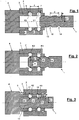
- Fig. 1 shows a theoretical sectional drawing of an exchangeable head 1 not yet inserted in the quick-connect coupling with a locking ring 2 in an unlocked position.
- the locking ring 2 and a ball-holding part 3 are parts of the quick-connect coupling, which are connected to a pressing device 4.
- balls K1 with a diameter D1 and further balls K2, likewise with the diameter D1 are disposed in ball guides 5, 6 such that they are radially movable.
- the balls K1, K2 act as movable locking bodies.
- the balls K1, K2 and the ball guides 5, 6 are distributed over the periphery of the ball-holding part 3.
- the ball-holding part 3 and the exchangeable head 1 are adjusted to one another, such that there is a sliding fit.
- Special shaping (see Fig. 4 ) of the ball guides 5, 6 on the inside of the ball-holding part 3 also prevents the balls K1, K2 from falling out when the exchangeable head 1 is not inserted or not inserted fully.
- the locking ring 2 is mounted on the ball-holding part 3 in an axially movable manner.
- the locking ring 2 has locating grooves 7, 8 on the inside, which are formed so that the balls K1, K2 can move away into the locating grooves 7, 8 when the locking ring 2 is in the unlocked position - as shown here -and thereby avoid obstructing the insertion of the exchangeable head 1.
- a spring element 9 that is mounted between the ball-holding part 3 and the locking ring 2 and permanently tries to press the locking ring 2 in an axial direction into the locking position (see Fig. 3 ). In order to achieve the unlocked position of the locking ring 2, as shown, the locking ring 2 must therefore be moved into this position manually by means of a gripping bar (not shown).
- the quick-connect coupling described creates a mechanically secure, but detachable connection between the pressing device 4 and the exchangeable head 1 and the pressing device 4 transmits compressive forces onto the exchangeable head 1, there is a plunger within the pressing device 4, via which pressure is transmitted onto an axially spring-mounted connecting rod within the exchangeable head 1 during operation by means of a contact surface on the plunger tip.
- these elements are not shown here.
- the quick-connect coupling is exposed to high axial forces with this sort of use, which act as traction forces and pull the pressing device 4 and the exchangeable head 1 apart.
- the exchangeable head 1 has a shaft part 13with a shaft radius R1.
- the shaft radius R1 of the exchangeable head 1 corresponds to the inside radii of the ball-holding part 3, naturally with corresponding tolerances for an easy-to-use sliding fit, because various exchangeable heads must be attachable to the pressing device.
- the exchangeable head 1 has a peripheral groove 14 with a groove depth N in the area of the shaft part 13 with the shaft radius R1.
- the peripheral groove 14 serves the partial holding of balls K1 with the pressing device 4 and the exchangeable head 1 in the connected state.
- the shaft part 13 has a further peripheral groove 15, likewise with the groove depth N and likewise in the area of the shaft part 13 with the shaft radius R1.
- the peripheral groove 15 serves to partially hold the balls K2 with the pressing device 4 and the exchangeable head 1 in the coupled state.
- the further peripheral groove 15 is disposed in the axial direction closer to the pressing device 4.
- the peripheral groove 14 and the further peripheral groove 15 naturally have the same axial spacing as the balls K1 and K2 in the ball-holding part, namely at a distance d.
- Fig. 3 shows a theoretical sectional drawing of an exchangeable head 1 completely inserted in the quick-connect coupling with the locking ring 2 in a locked position. It is made clear here that both the balls K1 and the further balls K2 are fixed in their radial position by stopping surfaces 16, 17 on the locking ring following complete insertion of the exchangeable head 1 and the advancing of the locking ring 2 (which is supported by the spring element 9), such that they have no more freedom of movement and the exchangeable head 1 is therefore locked in the quick-connect coupling.
- the balls K1, K2 now engage as a fixed locking body both with the shaft part 13 and also with the ball-holding part 3 and therefore prevent reciprocal movement.
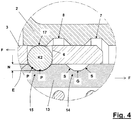
- Fig. 4 shows a detail of a sectional drawing of the quick-connect coupling for the theoretical shaping of the peripheral grooves 14, 15.
- the state shown corresponds to that shown in Fig. 3 and is the same in principle for both peripheral grooves 14, 15.
- the peripheral grooves 14, 15 each display a base surface G and side faces S, namely, such that the balls K1, K2 have a point contact with the base surface G and the side face S at locating points P in the connected state and the point contact with the side face occurs in the area of the half groove depth N.
- the side faces S may also be divided into several curve sections and neither is it necessary for the individual curve sections to be straight lines. Under load, pressure is therefore transmitted to the contact points P on the side faces S.
- the entry edges E of the peripheral grooves 14, 15 sensitive to deformation therefore remain unloaded.
Landscapes
- Engineering & Computer Science (AREA)
- Mechanical Engineering (AREA)
- Life Sciences & Earth Sciences (AREA)
- Forests & Forestry (AREA)
- Quick-Acting Or Multi-Walled Pipe Joints (AREA)
Description
- The invention relates to a quick-connect coupling for connecting an exchangeable head to a pressing device according to
patent claim 1. - Pressing devices are used for various purposes, such as, for example, pressing cable shoes onto electrical cables, but also for cutting cables or punching holes into sheet metal constructions. In order to perform these different applications on one machine, an exchangeable head system is required. To simplify matters, the different mountable heads are referred to in the following as exchangeable heads. Using the same pressing device with different exchangeable heads, it is quick and easy to change over to different applications where necessary.
- However, a particular problem affecting pressing devices with exchangeable heads is the longitudinal forces being transmitted, in other words, the compressive forces produced by the pressing devices, because the coupling mechanism by which the exchangeable head is attached to the pressing device naturally has to withstand these forces and the corresponding safety requirements are relatively high. The aim, therefore, is to find a coupling mechanism that can be handled quickly and easily and yet offers operational safety, even with high and very high longitudinal forces.
- Quick-connect coupling mechanisms are of course known per se. A quick-connect coupling mechanism used particularly frequently for torque transmission, especially in the field of hand machine tools, employs a solution with movable locking bodies, usually balls, which engage with corresponding grooves in the exchangeable tool in the connected state. An example of this is known from
DE-2 551 125 , whereby percussion drills are held in a tool holder on a machine tool in an easily exchangeable manner. Although longitudinal forces are naturally also active here, these are compressive forces (seen in relation to the machine tool/tool connection), so that there is no risk of the quick-connect coupling being released under load by the longitudinal forces and thereby representing a safety risk. - However, solutions are also known in which the same functional principle is also used with quick-connect couplings, where longitudinal forces are active, which represent traction forces in relation to the parts being connected. An example of this sort of connection is disclosed in
DE-1 108 528 . This specification shows a valve coupling for hose lines and pipelines. In this case, a coupling sleeve exhibits radial wall bores in which radially movable balls are disposed, which may project into a peripheral groove of a coupling plug. A spring-mounted locking sleeve prevents the balls from slipping out of the peripheral groove. Because this is an application in which pressurised fluids are conducted through connectable lines, although there is a certain safety risk, because evidently no applications involving very high fluid pressures are envisaged, additional measures do not seem necessary. - The situation is different, however, when the same functional principle is to be used in a quick-connect coupling to connect an exchangeable head to a powerful pressing device. Because relatively high pressures are used in this case (for example > 50 kN), special additional measures are needed in order to guarantee safety and reliability.
- The
WO-2004/091862 discloses a quick-action coupling cylinder that can also be used in a configuration where two opposite acting cylinders are adjacently positioned for holding onto a shaft having at least two identical grooves. The device is used for clamping two separate machine parts by means of locking balls onto a single shaft in a precisely positioned and shift-free manner. The two separate machine parts may e.g. be the two molds of an injection molding machine. However, each of the two separate machine parts holds onto the shaft by only just one groove. - The
DE-2614532 discloses a quick-connect coupling for a drill chuck, in accordance with the preamble ofclaim 1. The principle of using more than one coupling groove in conjunction with corresponding locking balls is employed. The design is such that a number of identical grooves are placed adjacently in a continuous row. A pressure body can thus be axially placed relative to the chuck housing at various discrete positions. - The
WO-2010/128131 discloses a medical hand-piece comprising a hollow shaft which can receive a treatment instrument. - The object of the invention, therefore, is to indicate a quick-connect coupling with loading capacity to connect an exchangeable head to a pressing device, wherein the quick-connect coupling is based on the known construction principle with movable locking bodies in the form of balls, which engage in corresponding grooves in an exchangeable head in the coupled state. This quick-connect coupling should endure high longitudinal traction forces on a sustained basis and, if possible, without wear and guarantee a high degree of safety.
- A further object involves the quick-connect coupling specified being designed in such a way that it is impossible for the pressing device and the interchangeable head to be wrongly assembled.
- This problem is solved by the features of
patent claim 1. - The solution involves in principle the use in a generic quick-connect coupling of a further peripheral groove on the exchangeable head, on the one hand, and a greater number of locking bodies (balls) and, on the other hand, a form being provided on the other side on a shaft section of the exchangeable head, which is disposed closer to the pressing device and makes locking impossible if the exchangeable head is used in the wrong position.
- In a general form, a generic quick-connect coupling between a first and a second component should be taken to mean the following in this case: In a ball-holding part on a first component (in this case the pressing device), a number of balls K1 with a diameter D1 is radially movably disposed. On a second component (in this case the exchangeable head) a peripheral groove with a groove depth N1 to partially hold the balls K1 is present on a shaft part in an area with a shaft radius R1 with the first and second components in a connected state. In this case, a locking ring is movably attached to the ball-holding part in an axial direction and in a spring-mounted manner, the balls K1 being held radially fixed in the peripheral groove by said locking ring when the first and second component are in the connected state.
- In concrete terms, the proposed solution means that
- on the shaft section of the exchangeable head there is a further peripheral groove,which is disposed closer to the pressing device in an axial direction, namely at a distance d from the peripheral groove,
- the further peripheral groove is designed to hold further balls K, wherein the further balls K are likewise disposed in a radially movable manner in the ball-holding part and wherein the further balls K are likewise spaced at a distance d, and
- the shaft section is disposed in an area that is closer to the pressing device in an axial direction and is likewise spaced at a distance d from the further peripheral groove, exhibits a form A that prevents the further balls K from moving radially when contact is made with the further balls K and thereby prevents the locking ring from moving.
- By using a further peripheral groove and with the associated use of a larger number of locking bodies (balls), it is possible to achieve the transmission of smaller forces per locking body (ball), or else the transmission of greater forces using the same measure. The proposed form A on the shaft section of the exchangeable head mean that if the exchangeable head is not completely inserted into the ball-holding part on the pressing device, a fixed connection cannot be made (in other words, a connection in which power is only transmitted across a single peripheral groove and the locking bodies engaging with it). Non-lockabilityin the event of incorrect assembly is of course particularly important, because this is exactly what must be completely and reliably prevented, due to the associated risks (breakage of the quick-connect coupling when there is a build-up of pressure). The proposed solution has the added advantage that it functions purely mechanically and does not require electronic monitoring.
- It has also emerged that with two peripheral grooves and a total of at least 12 balls - and of course using tool steels that are sufficiently hard and tough to avoid lasting deformation - the specified longitudinal forces in the region of 60 kN can be reliably transmitted.
- Also advantageous is an angularly offset arrangement of the balls K in the peripheral groove compared with the further balls K in the further peripheral groove. The forces can thereby be more effectively distributed over the entire cross-section.
- A further advantage is also that the proposed arrangement facilitates the unlimited twistability of the exchangeable head in relation to the pressing device.
- A further measure that ensures that the quick-connect coupling is able to withstand high longitudinal traction forces on a sustained basis and with as little wear as possible, involves the peripheral grooves each being provided with a base surface and side faces, namely in such a way that the balls K and the further balls K have a point contact with the base surface and the side faces in the connected state and that the point contact with the side face is made roughly in the region of the half groove depth N. This means that the locating point of the balls is moved from the entry edge of the peripheral grooves sensitive to deformation towards the entry centre of the peripheral grooves, which significantly increases wear resistance.
- An exemplary embodiment of the invention is described in greater detail below with the help of drawings. In the drawings
-
Fig. 1 shows a theoretical sectional drawing of an exchangeable head not yet inserted in the quick-connect coupling with the locking ring in an unlocked position, -
Fig. 2 shows a theoretical sectional drawing of an exchangeable head partly inserted in the quick-connect coupling with the locking ring in an unlocked position, -
Fig. 3 shows a theoretical sectional drawing of an exchangeable head completely inserted in the quick-connect coupling with the locking ring in a locked position and -
Fig. 4 shows a sectional detail drawing of the quick-connect coupling for the theoretical shaping of the peripheral grooves. -
Fig. 1 shows a theoretical sectional drawing of anexchangeable head 1 not yet inserted in the quick-connect coupling with alocking ring 2 in an unlocked position. In this case, thelocking ring 2 and a ball-holdingpart 3 are parts of the quick-connect coupling, which are connected to apressing device 4. In the ball-holdingpart 3, balls K1 with a diameter D1 and further balls K2, likewise with the diameter D1, are disposed inball guides ball guides holding part 3. Furthermore, the ball-holdingpart 3 and theexchangeable head 1 are adjusted to one another, such that there is a sliding fit. Special shaping (seeFig. 4 ) of theball guides part 3 also prevents the balls K1, K2 from falling out when theexchangeable head 1 is not inserted or not inserted fully. - The
locking ring 2 is mounted on the ball-holdingpart 3 in an axially movable manner. Thelocking ring 2 has locatinggrooves grooves locking ring 2 is in the unlocked position - as shown here -and thereby avoid obstructing the insertion of theexchangeable head 1. Not shown in this figure is aspring element 9 that is mounted between the ball-holdingpart 3 and thelocking ring 2 and permanently tries to press the lockingring 2 in an axial direction into the locking position (seeFig. 3 ). In order to achieve the unlocked position of thelocking ring 2, as shown, thelocking ring 2 must therefore be moved into this position manually by means of a gripping bar (not shown). - Since the quick-connect coupling described creates a mechanically secure, but detachable connection between the
pressing device 4 and theexchangeable head 1 and thepressing device 4 transmits compressive forces onto theexchangeable head 1, there is a plunger within thepressing device 4, via which pressure is transmitted onto an axially spring-mounted connecting rod within theexchangeable head 1 during operation by means of a contact surface on the plunger tip. To simplify the theoretical illustration and because they are not basically needed in order to understand the quick-connect coupling, these elements are not shown here. During operation, however, the quick-connect coupling is exposed to high axial forces with this sort of use, which act as traction forces and pull thepressing device 4 and theexchangeable head 1 apart. - The
exchangeable head 1 has a shaft part 13with a shaft radius R1. The shaft radius R1 of theexchangeable head 1 corresponds to the inside radii of the ball-holdingpart 3, naturally with corresponding tolerances for an easy-to-use sliding fit, because various exchangeable heads must be attachable to the pressing device. - The
exchangeable head 1 has aperipheral groove 14 with a groove depth N in the area of theshaft part 13 with the shaft radius R1. Theperipheral groove 14 serves the partial holding of balls K1 with thepressing device 4 and theexchangeable head 1 in the connected state. Theshaft part 13 has a furtherperipheral groove 15, likewise with the groove depth N and likewise in the area of theshaft part 13 with the shaft radius R1. Theperipheral groove 15 serves to partially hold the balls K2 with thepressing device 4 and theexchangeable head 1 in the coupled state. The furtherperipheral groove 15 is disposed in the axial direction closer to thepressing device 4. In addition, theperipheral groove 14 and the furtherperipheral groove 15 naturally have the same axial spacing as the balls K1 and K2 in the ball-holding part, namely at a distance d. - Based on the sizes introduced, it is easy to establish that with the proposed structural form with balls K1, K2 of the same size (i.e. the same diameter D1) and the same groove depth N for both
grooves Fig. 3 . - It is also true that with a structure of the type shown with the
shaft part 13 in an area disposed closer to thepressing device 4 in an axial direction and at a distance d from the furtherperipheral groove 15, there is a form A, which prevents the further balls K2 from moving radially when contact is made with the further balls K2 and therefore prevents thelocking ring 2 from moving. In this case, the form A is executed in its simplest form as an extension of the shaft part end with a constant radius R1 at least at a distance d from the secondperipheral groove 15. Other detail embodiments with the same effect are naturally possible. This form A means that no connection can be made between theexchangeable head 1 and thepressing device 4, in which the transmission of force only takes place via a single peripheral groove and the locking bodies (balls) engaging with it. This means that even in the case illustrated inFig. 2 , where theexchangeable head 1 is only inserted far enough for the furtherperipheral groove 15 to be located in the area of the balls K1 - a position in which thelocking ring 2 cannot be pushed into the locking position, due to the form A and the resulting blocking effect of the further balls K2 - no fixed connection can be made between theexchangeable head 1 and the pressing device, because the balls K1 can then still move way and are not fixable in the furtherperipheral groove 15. -
Fig. 3 shows a theoretical sectional drawing of anexchangeable head 1 completely inserted in the quick-connect coupling with thelocking ring 2 in a locked position. It is made clear here that both the balls K1 and the further balls K2 are fixed in their radial position by stoppingsurfaces exchangeable head 1 and the advancing of the locking ring 2 (which is supported by the spring element 9), such that they have no more freedom of movement and theexchangeable head 1 is therefore locked in the quick-connect coupling. The balls K1, K2 now engage as a fixed locking body both with theshaft part 13 and also with the ball-holdingpart 3 and therefore prevent reciprocal movement. -
Fig. 4 shows a detail of a sectional drawing of the quick-connect coupling for the theoretical shaping of theperipheral grooves Fig. 3 and is the same in principle for bothperipheral grooves peripheral grooves peripheral grooves peripheral grooves - However, in order to keep the permanent deformation by balls K1, K2 as small as possible with the great forces anticipated F, tests have revealed that the hardness of the steel used for the
shaft part 13 of theexchangeable head 4, for the ball-holdingpart 3 and for thelocking ring 2 must be at least 60 HRC. Apart from the high hardness level, the steels used must also exhibit adequate toughness. -
- 1
- Exchangeable head
- 2
- Locking ring
- 3
- Ball-holding part
- 4
- Pressing device
- 5
- Ball guide
- 6
- Ball guide
- 7
- Locating groove
- 8
- Locating groove
- 9
- Spring element
- 13
- Shaft part
- 14
- Peripheral groove
- 15
- Further peripheral groove
- 16
- Stopping surface
- 17
- Stopping surface
- K1
- Balls
- K2
- Further balls
- D1
- Diameter of the balls
- N
- Groove depth
- R1
- Shaft radius
- G
- Base surface of a peripheral groove
- S
- Side face of a peripheral groove
- P
- Locating point in the peripheral groove
- E
- Insertion edge of the peripheral groove
- F
- Axial force
Claims (7)
- A quick-connect coupling for connecting an exchangeable head (1) to a pressing device (4), wherein a number of balls (K1) with a diameter (D1) is radially movably disposed in a single ball-holding part (3) on the pressing device (4) and wherein a peripheral groove (14) with a groove depth (N) to partially hold the balls (K1) is present on a shaft part (13) with a radius (R1) with the pressing device (4) and the exchangeable head (1) in a connected state and wherein a single locking ring (2) is movably attached to the ball-holding part (3) in an axial direction, the balls (K1) being held radially fixed in the peripheral groove (14) by said locking ring when the pressing device (4) and the exchangeable head (1) are in the connected state, and where furthermore- on the shaft section (13) of the exchangeable head (1)there is a further peripheral groove (15), which is disposed closer to the pressing device (4) in an axial direction, namely at a distance (d) from the peripheral groove (14), and the further peripheral groove (15) is designed to hold further balls (K2), also with the diameter (D1), wherein the further balls (K2) are likewise disposed in a radially movable manner in the ball-holding part (3) and wherein the balls (K1) and the further balls (K2) in the ball-holding part (3) are likewise spaced at a distance (d), wherein in the ball-holding part (3), balls (K1) and further balls (K2) are disposed in ball guides (5, 6) such that they are radially movable and balls (K1, K2) and the ball guides (5, 6) are distributed over the periphery of ball-holding part (3), and the locking ring (2) has locating grooves (7, 8) on the inside, which are formed so that the balls (K1, K2) can move away into the locating grooves (7, 8) when the locking ring (2) is in the unlocked position,
characterised in that- the shaft part (13) is disposed in an area that is closer to the pressing device (4) in an axial direction and is likewise spaced at distance (d) from the further peripheral groove (15), exhibits a form (A) executed as an extension of the shaft part end with a constant radius (R1) at least at distance d from the peripheral groove (15), preventing the further balls (K2) from moving radially when contact is made with the further balls (K2) and therefore preventing the locking ring (2) from moving, such that it is impossible to lock the exchangeable head in the wrong position. - The quick-connect coupling according to patent claim 1, characterized in that the extension of the shaft part end with a constant radius (R1) is equal or greater than the distance (d) between the peripheral groove (14) and the further peripheral groove (15).
- The quick-connect coupling according to patent claim 1, characterised in that the balls (K1) and the further balls (K2) are of equal size.
- The quick-connect coupling according to patent claim 1, characterised in that a total of at least 12 balls (K1, K2) are distributed on the peripheral groove (14) and on the further peripheral groove (15) .
- The quick-connect coupling according to one of the patent claims 1, 3 or 4, characterised in that the balls (K1) are disposed angularly offset in the peripheral groove (14) compared with the further balls (K2) in the further peripheral groove (15).
- The quick-connect coupling according to one of the patent claims 1, 3, 4 or 5, characterised in that the peripheral grooves (14, 15) each exhibit a base surface (G) and side faces (S), in such a way that the balls (K1) and (K2) have a point contact with the base surface (G) and the side faces (S) at contact points (P) in the connected state and the point contact (P) with the side face (S) is made in the region of the half groove depth (N).
- The quick-connect coupling according to patent claim 6, characterised in that the side faces (S) are divided into several sections.
Applications Claiming Priority (1)
| Application Number | Priority Date | Filing Date | Title |
|---|---|---|---|
| CH01007/11A CH705122A1 (en) | 2011-06-16 | 2011-06-16 | Quick coupling for connecting a replaceable head. |
Publications (2)
| Publication Number | Publication Date |
|---|---|
| EP2535177A1 EP2535177A1 (en) | 2012-12-19 |
| EP2535177B1 true EP2535177B1 (en) | 2019-05-08 |
Family
ID=45851435
Family Applications (1)
| Application Number | Title | Priority Date | Filing Date |
|---|---|---|---|
| EP12160939.0A Active EP2535177B1 (en) | 2011-06-16 | 2012-03-23 | Quick-connect coupling |
Country Status (5)
| Country | Link |
|---|---|
| US (1) | US9242422B2 (en) |
| EP (1) | EP2535177B1 (en) |
| CN (1) | CN102829037B (en) |
| CA (1) | CA2776624A1 (en) |
| CH (1) | CH705122A1 (en) |
Families Citing this family (53)
| Publication number | Priority date | Publication date | Assignee | Title |
|---|---|---|---|---|
| WO2012171732A1 (en) * | 2011-06-16 | 2012-12-20 | Von Arx Ag | Quick coupling system for fastening an interchangeable head to a pressing tool |
| CH705122A1 (en) | 2011-06-16 | 2012-12-31 | Arx Ag | Quick coupling for connecting a replaceable head. |
| CH705121A1 (en) | 2011-06-16 | 2012-12-31 | Arx Ag | Quick coupling for connecting a replaceable head. |
| US9573263B2 (en) | 2012-04-18 | 2017-02-21 | Ridge Tool Company | Work tools having interchangeable work heads |
| CN202688184U (en) * | 2012-07-18 | 2013-01-23 | 深圳市华星光电技术有限公司 | Cutting device |
| DE102013103937B4 (en) * | 2013-04-18 | 2014-12-04 | Bilz Werkzeugfabrik Gmbh & Co. Kg | Quick change system for a tool holder |
| CN103307062B (en) * | 2013-06-06 | 2015-05-13 | 四川航天系统工程研究所 | Universal quick-locking connector |
| BR102013016280A2 (en) * | 2013-06-25 | 2015-08-18 | Dynamics Do Brasil Metalurgia Ltda | Hydraulic coupling enhancement for quick coupling |
| DE102013015506A1 (en) * | 2013-09-19 | 2015-03-19 | Wera-Werk Hermann Werner Gmbh & Co. Kg | socket |
| US9457227B2 (en) * | 2014-03-12 | 2016-10-04 | John Hetzel | Adjustable push-up apparatus |
| CN104326423A (en) * | 2014-10-24 | 2015-02-04 | 广州达意隆包装机械股份有限公司 | Shaped plate fixing mechanism and filling machine |
| CN104847804B (en) * | 2014-12-19 | 2018-06-19 | 北京宝沃汽车有限公司 | Quick Connect Kit and Engine Block Test equipment |
| CN104863945A (en) * | 2015-04-13 | 2015-08-26 | 苏州顺革智能科技有限公司 | Joint |
| WO2017095218A1 (en) * | 2015-12-04 | 2017-06-08 | Prolyte Group B.V. | Coupling for connecting construction parts, a truss provided therewith and associated method and use |
| EP3411537B1 (en) | 2016-02-05 | 2019-11-13 | Prolyte Group B.V. | Coupling for connecting construction parts, a truss provided therewith and associated method and use |
| DE102017204387A1 (en) | 2016-12-16 | 2018-06-21 | Ridge Tool Company | Tool heads and tool systems |
| DE202016107318U1 (en) * | 2016-12-23 | 2017-01-24 | Resbig Technology Gmbh | Manually actuated locking device |
| CN107044472B (en) * | 2017-06-01 | 2022-08-23 | 湖北文理学院 | Quick connecting mechanism |
| CN107387581A (en) * | 2017-09-13 | 2017-11-24 | 安徽省农业科学院蚕桑研究所 | It is a kind of to follow the multifunctional assembled attachment means cut and cut down hay mover automatically |
| US11162290B2 (en) * | 2017-10-19 | 2021-11-02 | Ford Motor Company | Automatic bump stop assembly |
| WO2019108539A1 (en) | 2017-11-28 | 2019-06-06 | Hubbell Incorporated | Portable hand-held power tool with interchangeable head |
| WO2019160794A1 (en) | 2018-02-14 | 2019-08-22 | Milwaukee Electric Tool Corporation | Powered threaded rod cutter |
| WO2019183311A1 (en) | 2018-03-23 | 2019-09-26 | Milwaukee Electric Tool Corporation | Attachment mechanism for a power tool |
| CN108436123B (en) * | 2018-03-27 | 2020-11-24 | 江苏高精机电装备有限公司 | Anchor clamps suitable for quick clamping of thin wall part |
| CN110860927B (en) * | 2018-08-27 | 2021-05-14 | 晟进科技股份有限公司 | Multipurpose chuck |
| EP3663047B1 (en) | 2018-12-07 | 2021-09-01 | Von Arx AG | Press apparatus with securing element |
| CN109895166B (en) * | 2019-03-26 | 2024-06-18 | 广州市兴世机械制造有限公司 | Slitting mechanism and breast pad production line using same |
| DE102019115386A1 (en) | 2019-06-06 | 2020-12-10 | Wto Vermögensverwaltung Gmbh | Operating key for stationary and driven tool holders |
| EP4003627A4 (en) * | 2019-07-27 | 2023-08-16 | Davis, Eric Alain | TOOL ADAPTER |
| EP3789648B1 (en) | 2019-09-06 | 2024-01-03 | ODU GmbH & Co. KG | Ball-lock connector |
| US20210362315A1 (en) * | 2019-09-23 | 2021-11-25 | Tien-I Industrial Co., Ltd. | Impact tool head |
| US12617064B2 (en) | 2019-09-23 | 2026-05-05 | Tien-I Industrial Co., Ltd. | Impact tool head |
| CN111129866B (en) * | 2019-12-24 | 2025-06-03 | 安徽博微联控科技有限公司 | Charging conversion connection device and method for charging type stereo garage |
| JP7477308B2 (en) * | 2020-01-20 | 2024-05-01 | 株式会社Subaru | Shank for cutting tool, cutting tool and cutting method |
| CN111348018B (en) * | 2020-04-09 | 2023-08-29 | 西安航空制动科技有限公司 | Brake instruction sensor interface assembly and design method thereof |
| CN111706254A (en) * | 2020-06-19 | 2020-09-25 | 南京浦裕投资有限公司 | Drilling machine for engineering construction |
| WO2022005929A1 (en) | 2020-07-02 | 2022-01-06 | Milwaukee Electric Tool Corporation | Rotary impact tool having bit holding device |
| CN113969924B (en) * | 2020-07-22 | 2026-01-06 | 舍弗勒投资(中国)有限公司 | Connection mechanism and shaft/sleeve assembly |
| AU2021350005A1 (en) * | 2020-09-24 | 2023-04-27 | Mako Surgical Corp. | Interlocking collet system for a surgical device |
| CN214443619U (en) | 2020-11-27 | 2021-10-22 | 米沃奇电动工具公司 | Electric threaded rod cutting machine |
| EP4011559B1 (en) * | 2020-12-09 | 2025-01-29 | Dubuis et Cie | Device having a quick coupling system for fastening an exchangeable head |
| CN112655301B (en) * | 2020-12-18 | 2022-08-12 | 东北农业大学 | A fast docking mechanism for tractor and agricultural machinery |
| DE102021104616A1 (en) | 2021-02-26 | 2022-09-01 | Bayerische Motoren Werke Aktiengesellschaft | Socket and screwdriver with socket |
| CN113043203A (en) * | 2021-04-16 | 2021-06-29 | 宁波泓谊塑胶科技有限公司 | Telescopic screwdriver |
| CN113172248B (en) * | 2021-04-25 | 2024-05-28 | 浙江欣兴工具股份有限公司 | Locking mechanism, positioning device and locking method |
| CN113188783B (en) * | 2021-04-28 | 2022-12-16 | 上海理工大学 | Torque performance testing device for real-time visualization of torque of surgical instrument |
| DE102021204606A1 (en) * | 2021-05-06 | 2022-11-10 | Robert Bosch Gesellschaft mit beschränkter Haftung | suction adapter |
| KR102388811B1 (en) * | 2021-06-10 | 2022-04-21 | 에스케이에코플랜트(주) | Apparatus for fastening and electrical house including the same |
| CN113339610B (en) * | 2021-06-29 | 2022-08-05 | 宁波康韩瑞电器有限公司 | Quick butt joint structure of interface for air conditioner |
| JP7735440B2 (en) * | 2022-02-04 | 2025-09-08 | 日東工器株式会社 | Tool Mounting Unit |
| US12644481B2 (en) * | 2022-05-27 | 2026-06-02 | Compx International Inc. | Quick release pin marine mount system for quick release accessories |
| KR102474918B1 (en) * | 2022-10-07 | 2022-12-07 | 주식회사 삼우에코 | Air knife of baffle device |
| CN116398549A (en) * | 2023-05-09 | 2023-07-07 | 无锡摩帕商贸有限公司 | Rail-changing coupler |
Family Cites Families (50)
| Publication number | Priority date | Publication date | Assignee | Title |
|---|---|---|---|---|
| US68567A (en) | 1867-09-03 | Improved nail-clincher | ||
| US2255695A (en) * | 1938-05-12 | 1941-09-09 | Clinton H M Bull | Sucker rod locking means |
| US2255333A (en) * | 1938-10-08 | 1941-09-09 | Albert T Scheiwer | Coupling |
| DE1108528B (en) | 1958-04-23 | 1961-06-08 | Walther Technik Carl Kurt Walt | Valve coupling for hose or pipelines |
| US3190168A (en) * | 1960-01-25 | 1965-06-22 | Sullivan Leonard Ray | Quick detachable fastening means |
| SE316967B (en) | 1967-09-15 | 1969-11-03 | E Jahrl | |
| SE374288B (en) | 1973-06-04 | 1975-03-03 | Eminentverktyg Ab | |
| US3937055A (en) | 1974-11-06 | 1976-02-10 | The United States Of America As Represented By The United States National Aeronautics And Space Administration | Method of peening and portable peening gun |
| FR2306909A1 (en) | 1975-04-10 | 1976-11-05 | Vallourec | Lift and transfer pipe conveyor - has two rollers each attached to pivoting arm activated by double acting cylinder |
| DE7536182U (en) | 1975-11-14 | 1978-02-02 | Robert Bosch Gmbh, 7000 Stuttgart | DEVICE FOR TORQUE TRANSMISSION |
| DE2614532B1 (en) | 1976-04-03 | 1977-09-15 | Hanns Dipl-Ing Schnitzler | DRILL CHUCK WITH DRILL SPIRAL |
| FR2437910A1 (en) * | 1978-10-06 | 1980-04-30 | Lauricella Robert | Chuck for rotary milling cutter - uses relative rotation of oval ring on round body to give ball convergence on ramped faces split sleeve which displaces axially |
| EP0253177A2 (en) | 1986-07-10 | 1988-01-20 | The Perkin-Elmer Corporation | Multiple outlet powder pickup system for thermal spray guns |
| DE3719893A1 (en) | 1987-06-13 | 1988-12-29 | Wagner Paul Heinz | HYDRAULIC SCREWDRIVER |
| DE10216213A1 (en) | 2002-04-10 | 2003-10-23 | Klauke Gmbh Gustav | Electro-hydraulic pressing device and method for operating the same |
| FR2649028B1 (en) | 1989-06-28 | 1994-05-06 | Snecma | DEVICE FOR AUTOMATICALLY TAKING A TOOL HOLDER OR TOOL |
| JPH0342199A (en) | 1989-07-06 | 1991-02-22 | Toshiba Mach Co Ltd | Device for clamping stamp and mortar |
| US5209153A (en) | 1990-02-28 | 1993-05-11 | Daia Industry Co., Ltd. | Portable hydraulically operated device incorporating automatic drain valve |
| US5253554A (en) | 1992-11-27 | 1993-10-19 | Riera Salvatore J | Power driven hose clamp tool |
| SE505162C2 (en) | 1995-03-22 | 1997-07-07 | Pressmaster Tool Ab | Tool head |
| US5957634A (en) * | 1997-03-07 | 1999-09-28 | Carpinetti; David J. | Quick change drill extender system |
| DE19716804A1 (en) | 1997-04-22 | 1998-10-29 | Klauke Gmbh Gustav | Electric handheld device |
| US6290606B1 (en) * | 1997-09-19 | 2001-09-18 | The Charles Machines Works, Inc. | Polygonal ball drive system for earth auger |
| DE19825160A1 (en) | 1997-10-15 | 1999-04-22 | Klauke Gmbh Gustav | Hydraulic press device e.g. for connecting cable shoes to electrical cables or for riveting |
| US6511268B1 (en) | 1999-08-13 | 2003-01-28 | Maxtech Manufacturing Inc. | Tool device with reversible drill bit/screw bit |
| DE19944229B4 (en) | 1999-09-15 | 2016-07-28 | Gustav Klauke Gmbh | Hydraulic hand press and replaceable head for this purpose |
| US6324768B1 (en) | 2000-04-18 | 2001-12-04 | Aip, Inc. | Ball lock punch retainer and checking gage system |
| US6324884B1 (en) | 2000-06-30 | 2001-12-04 | Mastercool, Inc. | Hand-held portable crimping tool |
| DE20012706U1 (en) | 2000-07-21 | 2000-09-28 | Maschinenfabrik Lorenz GmbH, 76275 Ettlingen | Interchangeable part for workpiece clamping device and workpiece clamping device adapted to it |
| DE10046869C2 (en) | 2000-09-20 | 2002-10-24 | Henkel Kgaa | Tableting punches |
| US7140817B1 (en) * | 2002-07-23 | 2006-11-28 | Black & Decker Inc. | Router bit system |
| DE602004029213D1 (en) | 2003-02-18 | 2010-11-04 | Greenlee Textron Inc | Quick-change spindle unit for hole saw |
| US6953196B1 (en) * | 2003-03-31 | 2005-10-11 | Daniel Huang | Non-inflation adapter for prompt engagement with a shank of a screw driver and a handle |
| DE10317341B4 (en) * | 2003-04-15 | 2014-03-20 | Andreas Maier Gmbh & Co. Kg | Quick release cylinder with guide device |
| DE20312887U1 (en) | 2003-08-21 | 2003-10-09 | Festool GmbH, 73240 Wendlingen | Mounting shaft for rotating tool has a polygonal cross section with rounded edges on a circle |
| US7641415B2 (en) * | 2006-01-31 | 2010-01-05 | Deere & Company | Automatic locking ball coupler for power take off |
| US8636287B2 (en) | 2006-04-13 | 2014-01-28 | Insty Bit Acquisition, Llc | Automatic tool-bit holder |
| US7839053B2 (en) * | 2007-03-28 | 2010-11-23 | Hoya Corporation | One-way rotational transfer mechanism, and ultrasonic rotary drive device incorporating one-way rotational transfer mechanism |
| US8251606B2 (en) * | 2007-08-31 | 2012-08-28 | The Blanchard Patent Holding Company, Llc | Fastener and assembly utilizing the same |
| US8074485B2 (en) | 2008-07-08 | 2011-12-13 | Tyco Electronics Corporation | Tool head assemblies for pressing devices |
| CN101769279A (en) * | 2008-12-31 | 2010-07-07 | 中国航空工业第一集团公司第六三一研究所 | Locking device |
| EP2233103B1 (en) * | 2009-03-26 | 2017-11-15 | W & H Dentalwerk Bürmoos GmbH | Medical, in particular dental handpiece |
| JP5422044B2 (en) * | 2009-05-07 | 2014-02-19 | ヴェー ウント ハー デンタルヴェルク ビュールモース ゲーエムベーハー | Medical handpiece |
| DE202009010128U1 (en) | 2009-07-24 | 2009-10-08 | Josef Weischer Gmbh | punching device |
| CH705121A1 (en) | 2011-06-16 | 2012-12-31 | Arx Ag | Quick coupling for connecting a replaceable head. |
| WO2012171732A1 (en) | 2011-06-16 | 2012-12-20 | Von Arx Ag | Quick coupling system for fastening an interchangeable head to a pressing tool |
| CH705122A1 (en) | 2011-06-16 | 2012-12-31 | Arx Ag | Quick coupling for connecting a replaceable head. |
| CN102619739B (en) | 2012-04-09 | 2015-04-15 | 台州巨力工具有限公司 | Variable plunger pump |
| US9573263B2 (en) | 2012-04-18 | 2017-02-21 | Ridge Tool Company | Work tools having interchangeable work heads |
| CN105264723B (en) | 2013-05-28 | 2018-01-26 | 里奇工具公司 | Power tool with interchangeable work head |
-
2011
- 2011-06-16 CH CH01007/11A patent/CH705122A1/en not_active Application Discontinuation
-
2012
- 2012-03-23 EP EP12160939.0A patent/EP2535177B1/en active Active
- 2012-04-18 US US13/449,821 patent/US9242422B2/en active Active
- 2012-05-10 CA CA2776624A patent/CA2776624A1/en not_active Abandoned
- 2012-06-13 CN CN201210194064.0A patent/CN102829037B/en not_active Expired - Fee Related
Non-Patent Citations (1)
| Title |
|---|
| None * |
Also Published As
| Publication number | Publication date |
|---|---|
| CN102829037B (en) | 2016-08-31 |
| CH705122A1 (en) | 2012-12-31 |
| CA2776624A1 (en) | 2012-12-16 |
| US20120319399A1 (en) | 2012-12-20 |
| US9242422B2 (en) | 2016-01-26 |
| EP2535177A1 (en) | 2012-12-19 |
| CN102829037A (en) | 2012-12-19 |
Similar Documents
| Publication | Publication Date | Title |
|---|---|---|
| EP2535177A1 (en) | Quick-connect coupling | |
| EP2535128B1 (en) | Quick-connect coupling | |
| US10364620B2 (en) | Drill rod clamping system and methods of using same | |
| US10150169B2 (en) | System for releasable coupling of a hole saw to a drill arbor | |
| US8147173B2 (en) | Adapter for operating a keyhole saw on a driving machine | |
| EP3408054B1 (en) | Device for the locking of pieces on machine tools | |
| US10722949B2 (en) | Coupling for connecting an interchangeable tool head to a machine part of a pressing device | |
| US9387539B2 (en) | Gripper with emergency release | |
| EP2087957B1 (en) | Rotary tool system with centering member | |
| US4844482A (en) | Drill chuck | |
| DE3443186A1 (en) | Chuck for powered hand tools, in particular drilling and/or impact hammers | |
| US20090279969A1 (en) | A fixation device for fixating a portable drilling machine to a drill template | |
| EP2039450A2 (en) | Separable mechanical coupling | |
| US20030002939A1 (en) | Boring head | |
| EP0387228B1 (en) | Tool coupling between a toolholder and a machine spindle | |
| JP7583748B2 (en) | Clamping device for tool holders | |
| US4777714A (en) | Quick-change mount for chucks | |
| US20120309601A1 (en) | Revolver disk and tool holder for a cutting tool | |
| DE102013006831A1 (en) | Clamping system for clamping a punch on a plunger of a flow pressure press | |
| DE102011116572A1 (en) | Clamping device for detachably holding tool retainer or tool with polygonal hollow shaft cone in exchangeable tool holder, has bolt rotated against force of springs away from releasing position over dead point in locked clamping position | |
| SE546196C2 (en) | Power Tool with a Coupling Mechanism comprising two biasing elements | |
| EP2719488A1 (en) | Toolholder with elastic finger clamping arrangement and cutting tool having a toolholder and a replaceable cutting head | |
| EP1657013B1 (en) | Tool holder | |
| CN214393888U (en) | Positioning mechanism | |
| JP2011016196A (en) | Coupling device |
Legal Events
| Date | Code | Title | Description |
|---|---|---|---|
| PUAI | Public reference made under article 153(3) epc to a published international application that has entered the european phase |
Free format text: ORIGINAL CODE: 0009012 |
|
| AK | Designated contracting states |
Kind code of ref document: A1 Designated state(s): AL AT BE BG CH CY CZ DE DK EE ES FI FR GB GR HR HU IE IS IT LI LT LU LV MC MK MT NL NO PL PT RO RS SE SI SK SM TR |
|
| AX | Request for extension of the european patent |
Extension state: BA ME |
|
| 17P | Request for examination filed |
Effective date: 20130603 |
|
| RBV | Designated contracting states (corrected) |
Designated state(s): AL AT BE BG CH CY CZ DE DK EE ES FI FR GB GR HR HU IE IS IT LI LT LU LV MC MK MT NL NO PL PT RO RS SE SI SK SM TR |
|
| STAA | Information on the status of an ep patent application or granted ep patent |
Free format text: STATUS: EXAMINATION IS IN PROGRESS |
|
| 17Q | First examination report despatched |
Effective date: 20180104 |
|
| GRAP | Despatch of communication of intention to grant a patent |
Free format text: ORIGINAL CODE: EPIDOSNIGR1 |
|
| STAA | Information on the status of an ep patent application or granted ep patent |
Free format text: STATUS: GRANT OF PATENT IS INTENDED |
|
| RIC1 | Information provided on ipc code assigned before grant |
Ipc: B23B 31/107 20060101ALI20181031BHEP Ipc: B26F 1/40 20060101ALI20181031BHEP Ipc: B30B 15/02 20060101AFI20181031BHEP Ipc: B25B 23/00 20060101ALI20181031BHEP Ipc: B23Q 1/00 20060101ALI20181031BHEP Ipc: B26D 7/26 20060101ALI20181031BHEP Ipc: B21D 28/34 20060101ALI20181031BHEP Ipc: F16B 21/16 20060101ALI20181031BHEP |
|
| INTG | Intention to grant announced |
Effective date: 20181122 |
|
| GRAS | Grant fee paid |
Free format text: ORIGINAL CODE: EPIDOSNIGR3 |
|
| GRAA | (expected) grant |
Free format text: ORIGINAL CODE: 0009210 |
|
| STAA | Information on the status of an ep patent application or granted ep patent |
Free format text: STATUS: THE PATENT HAS BEEN GRANTED |
|
| AK | Designated contracting states |
Kind code of ref document: B1 Designated state(s): AL AT BE BG CH CY CZ DE DK EE ES FI FR GB GR HR HU IE IS IT LI LT LU LV MC MK MT NL NO PL PT RO RS SE SI SK SM TR |
|
| REG | Reference to a national code |
Ref country code: GB Ref legal event code: FG4D |
|
| REG | Reference to a national code |
Ref country code: CH Ref legal event code: EP Ref country code: AT Ref legal event code: REF Ref document number: 1129514 Country of ref document: AT Kind code of ref document: T Effective date: 20190515 |
|
| REG | Reference to a national code |
Ref country code: IE Ref legal event code: FG4D |
|
| REG | Reference to a national code |
Ref country code: DE Ref legal event code: R096 Ref document number: 602012059776 Country of ref document: DE |
|
| REG | Reference to a national code |
Ref country code: NL Ref legal event code: MP Effective date: 20190508 |
|
| REG | Reference to a national code |
Ref country code: LT Ref legal event code: MG4D |
|
| PG25 | Lapsed in a contracting state [announced via postgrant information from national office to epo] |
Ref country code: NL Free format text: LAPSE BECAUSE OF FAILURE TO SUBMIT A TRANSLATION OF THE DESCRIPTION OR TO PAY THE FEE WITHIN THE PRESCRIBED TIME-LIMIT Effective date: 20190508 Ref country code: HR Free format text: LAPSE BECAUSE OF FAILURE TO SUBMIT A TRANSLATION OF THE DESCRIPTION OR TO PAY THE FEE WITHIN THE PRESCRIBED TIME-LIMIT Effective date: 20190508 Ref country code: LT Free format text: LAPSE BECAUSE OF FAILURE TO SUBMIT A TRANSLATION OF THE DESCRIPTION OR TO PAY THE FEE WITHIN THE PRESCRIBED TIME-LIMIT Effective date: 20190508 Ref country code: NO Free format text: LAPSE BECAUSE OF FAILURE TO SUBMIT A TRANSLATION OF THE DESCRIPTION OR TO PAY THE FEE WITHIN THE PRESCRIBED TIME-LIMIT Effective date: 20190808 Ref country code: FI Free format text: LAPSE BECAUSE OF FAILURE TO SUBMIT A TRANSLATION OF THE DESCRIPTION OR TO PAY THE FEE WITHIN THE PRESCRIBED TIME-LIMIT Effective date: 20190508 Ref country code: SE Free format text: LAPSE BECAUSE OF FAILURE TO SUBMIT A TRANSLATION OF THE DESCRIPTION OR TO PAY THE FEE WITHIN THE PRESCRIBED TIME-LIMIT Effective date: 20190508 Ref country code: PT Free format text: LAPSE BECAUSE OF FAILURE TO SUBMIT A TRANSLATION OF THE DESCRIPTION OR TO PAY THE FEE WITHIN THE PRESCRIBED TIME-LIMIT Effective date: 20190908 Ref country code: AL Free format text: LAPSE BECAUSE OF FAILURE TO SUBMIT A TRANSLATION OF THE DESCRIPTION OR TO PAY THE FEE WITHIN THE PRESCRIBED TIME-LIMIT Effective date: 20190508 Ref country code: ES Free format text: LAPSE BECAUSE OF FAILURE TO SUBMIT A TRANSLATION OF THE DESCRIPTION OR TO PAY THE FEE WITHIN THE PRESCRIBED TIME-LIMIT Effective date: 20190508 |
|
| PG25 | Lapsed in a contracting state [announced via postgrant information from national office to epo] |
Ref country code: GR Free format text: LAPSE BECAUSE OF FAILURE TO SUBMIT A TRANSLATION OF THE DESCRIPTION OR TO PAY THE FEE WITHIN THE PRESCRIBED TIME-LIMIT Effective date: 20190809 Ref country code: BG Free format text: LAPSE BECAUSE OF FAILURE TO SUBMIT A TRANSLATION OF THE DESCRIPTION OR TO PAY THE FEE WITHIN THE PRESCRIBED TIME-LIMIT Effective date: 20190808 Ref country code: RS Free format text: LAPSE BECAUSE OF FAILURE TO SUBMIT A TRANSLATION OF THE DESCRIPTION OR TO PAY THE FEE WITHIN THE PRESCRIBED TIME-LIMIT Effective date: 20190508 Ref country code: LV Free format text: LAPSE BECAUSE OF FAILURE TO SUBMIT A TRANSLATION OF THE DESCRIPTION OR TO PAY THE FEE WITHIN THE PRESCRIBED TIME-LIMIT Effective date: 20190508 |
|
| REG | Reference to a national code |
Ref country code: AT Ref legal event code: MK05 Ref document number: 1129514 Country of ref document: AT Kind code of ref document: T Effective date: 20190508 |
|
| PG25 | Lapsed in a contracting state [announced via postgrant information from national office to epo] |
Ref country code: EE Free format text: LAPSE BECAUSE OF FAILURE TO SUBMIT A TRANSLATION OF THE DESCRIPTION OR TO PAY THE FEE WITHIN THE PRESCRIBED TIME-LIMIT Effective date: 20190508 Ref country code: AT Free format text: LAPSE BECAUSE OF FAILURE TO SUBMIT A TRANSLATION OF THE DESCRIPTION OR TO PAY THE FEE WITHIN THE PRESCRIBED TIME-LIMIT Effective date: 20190508 Ref country code: DK Free format text: LAPSE BECAUSE OF FAILURE TO SUBMIT A TRANSLATION OF THE DESCRIPTION OR TO PAY THE FEE WITHIN THE PRESCRIBED TIME-LIMIT Effective date: 20190508 Ref country code: CZ Free format text: LAPSE BECAUSE OF FAILURE TO SUBMIT A TRANSLATION OF THE DESCRIPTION OR TO PAY THE FEE WITHIN THE PRESCRIBED TIME-LIMIT Effective date: 20190508 Ref country code: RO Free format text: LAPSE BECAUSE OF FAILURE TO SUBMIT A TRANSLATION OF THE DESCRIPTION OR TO PAY THE FEE WITHIN THE PRESCRIBED TIME-LIMIT Effective date: 20190508 Ref country code: SK Free format text: LAPSE BECAUSE OF FAILURE TO SUBMIT A TRANSLATION OF THE DESCRIPTION OR TO PAY THE FEE WITHIN THE PRESCRIBED TIME-LIMIT Effective date: 20190508 |
|
| REG | Reference to a national code |
Ref country code: DE Ref legal event code: R097 Ref document number: 602012059776 Country of ref document: DE |
|
| PG25 | Lapsed in a contracting state [announced via postgrant information from national office to epo] |
Ref country code: SM Free format text: LAPSE BECAUSE OF FAILURE TO SUBMIT A TRANSLATION OF THE DESCRIPTION OR TO PAY THE FEE WITHIN THE PRESCRIBED TIME-LIMIT Effective date: 20190508 Ref country code: IT Free format text: LAPSE BECAUSE OF FAILURE TO SUBMIT A TRANSLATION OF THE DESCRIPTION OR TO PAY THE FEE WITHIN THE PRESCRIBED TIME-LIMIT Effective date: 20190508 |
|
| PLBE | No opposition filed within time limit |
Free format text: ORIGINAL CODE: 0009261 |
|
| STAA | Information on the status of an ep patent application or granted ep patent |
Free format text: STATUS: NO OPPOSITION FILED WITHIN TIME LIMIT |
|
| PG25 | Lapsed in a contracting state [announced via postgrant information from national office to epo] |
Ref country code: TR Free format text: LAPSE BECAUSE OF FAILURE TO SUBMIT A TRANSLATION OF THE DESCRIPTION OR TO PAY THE FEE WITHIN THE PRESCRIBED TIME-LIMIT Effective date: 20190508 |
|
| 26N | No opposition filed |
Effective date: 20200211 |
|
| PG25 | Lapsed in a contracting state [announced via postgrant information from national office to epo] |
Ref country code: PL Free format text: LAPSE BECAUSE OF FAILURE TO SUBMIT A TRANSLATION OF THE DESCRIPTION OR TO PAY THE FEE WITHIN THE PRESCRIBED TIME-LIMIT Effective date: 20190508 |
|
| PG25 | Lapsed in a contracting state [announced via postgrant information from national office to epo] |
Ref country code: SI Free format text: LAPSE BECAUSE OF FAILURE TO SUBMIT A TRANSLATION OF THE DESCRIPTION OR TO PAY THE FEE WITHIN THE PRESCRIBED TIME-LIMIT Effective date: 20190508 |
|
| PG25 | Lapsed in a contracting state [announced via postgrant information from national office to epo] |
Ref country code: MC Free format text: LAPSE BECAUSE OF FAILURE TO SUBMIT A TRANSLATION OF THE DESCRIPTION OR TO PAY THE FEE WITHIN THE PRESCRIBED TIME-LIMIT Effective date: 20190508 |
|
| REG | Reference to a national code |
Ref country code: BE Ref legal event code: MM Effective date: 20200331 |
|
| PG25 | Lapsed in a contracting state [announced via postgrant information from national office to epo] |
Ref country code: LU Free format text: LAPSE BECAUSE OF NON-PAYMENT OF DUE FEES Effective date: 20200323 |
|
| PG25 | Lapsed in a contracting state [announced via postgrant information from national office to epo] |
Ref country code: IE Free format text: LAPSE BECAUSE OF NON-PAYMENT OF DUE FEES Effective date: 20200323 Ref country code: FR Free format text: LAPSE BECAUSE OF NON-PAYMENT OF DUE FEES Effective date: 20200331 |
|
| PG25 | Lapsed in a contracting state [announced via postgrant information from national office to epo] |
Ref country code: BE Free format text: LAPSE BECAUSE OF NON-PAYMENT OF DUE FEES Effective date: 20200331 |
|
| GBPC | Gb: european patent ceased through non-payment of renewal fee |
Effective date: 20200323 |
|
| PG25 | Lapsed in a contracting state [announced via postgrant information from national office to epo] |
Ref country code: GB Free format text: LAPSE BECAUSE OF NON-PAYMENT OF DUE FEES Effective date: 20200323 |
|
| PG25 | Lapsed in a contracting state [announced via postgrant information from national office to epo] |
Ref country code: MT Free format text: LAPSE BECAUSE OF FAILURE TO SUBMIT A TRANSLATION OF THE DESCRIPTION OR TO PAY THE FEE WITHIN THE PRESCRIBED TIME-LIMIT Effective date: 20190508 Ref country code: CY Free format text: LAPSE BECAUSE OF FAILURE TO SUBMIT A TRANSLATION OF THE DESCRIPTION OR TO PAY THE FEE WITHIN THE PRESCRIBED TIME-LIMIT Effective date: 20190508 |
|
| PG25 | Lapsed in a contracting state [announced via postgrant information from national office to epo] |
Ref country code: MK Free format text: LAPSE BECAUSE OF FAILURE TO SUBMIT A TRANSLATION OF THE DESCRIPTION OR TO PAY THE FEE WITHIN THE PRESCRIBED TIME-LIMIT Effective date: 20190508 Ref country code: IS Free format text: LAPSE BECAUSE OF FAILURE TO SUBMIT A TRANSLATION OF THE DESCRIPTION OR TO PAY THE FEE WITHIN THE PRESCRIBED TIME-LIMIT Effective date: 20190908 |
|
| PGFP | Annual fee paid to national office [announced via postgrant information from national office to epo] |
Ref country code: DE Payment date: 20230221 Year of fee payment: 12 |
|
| REG | Reference to a national code |
Ref country code: DE Ref legal event code: R081 Ref document number: 602012059776 Country of ref document: DE Owner name: EMERSON PROFESSIONAL TOOLS AG, CH Free format text: FORMER OWNER: VON ARX AG, SISSACH, CH |
|
| P01 | Opt-out of the competence of the unified patent court (upc) registered |
Effective date: 20230615 |
|
| PGFP | Annual fee paid to national office [announced via postgrant information from national office to epo] |
Ref country code: CH Payment date: 20230703 Year of fee payment: 12 |
|
| REG | Reference to a national code |
Ref country code: DE Ref legal event code: R119 Ref document number: 602012059776 Country of ref document: DE |
|
| REG | Reference to a national code |
Ref country code: CH Ref legal event code: PL |
|
| PG25 | Lapsed in a contracting state [announced via postgrant information from national office to epo] |
Ref country code: DE Free format text: LAPSE BECAUSE OF NON-PAYMENT OF DUE FEES Effective date: 20241001 |
|
| PG25 | Lapsed in a contracting state [announced via postgrant information from national office to epo] |
Ref country code: DE Free format text: LAPSE BECAUSE OF NON-PAYMENT OF DUE FEES Effective date: 20241001 Ref country code: CH Free format text: LAPSE BECAUSE OF NON-PAYMENT OF DUE FEES Effective date: 20240331 |