EP2535173A1 - Tire vulcanizer and tire vulcanizing method - Google Patents
Tire vulcanizer and tire vulcanizing method Download PDFInfo
- Publication number
- EP2535173A1 EP2535173A1 EP12169714A EP12169714A EP2535173A1 EP 2535173 A1 EP2535173 A1 EP 2535173A1 EP 12169714 A EP12169714 A EP 12169714A EP 12169714 A EP12169714 A EP 12169714A EP 2535173 A1 EP2535173 A1 EP 2535173A1
- Authority
- EP
- European Patent Office
- Prior art keywords
- medium
- passage
- vulcanization
- nitrogen gas
- pressure
- Prior art date
- Legal status (The legal status is an assumption and is not a legal conclusion. Google has not performed a legal analysis and makes no representation as to the accuracy of the status listed.)
- Granted
Links
- 238000000034 method Methods 0.000 title claims description 11
- 238000004073 vulcanization Methods 0.000 claims abstract description 140
- 230000007246 mechanism Effects 0.000 claims abstract description 104
- 238000010438 heat treatment Methods 0.000 claims abstract description 95
- 238000000059 patterning Methods 0.000 claims abstract description 58
- 238000011144 upstream manufacturing Methods 0.000 claims abstract description 18
- 238000007493 shaping process Methods 0.000 claims description 17
- IJGRMHOSHXDMSA-UHFFFAOYSA-N Atomic nitrogen Chemical compound N#N IJGRMHOSHXDMSA-UHFFFAOYSA-N 0.000 abstract description 187
- 229910001873 dinitrogen Inorganic materials 0.000 abstract description 187
- 239000007789 gas Substances 0.000 description 101
- 230000003247 decreasing effect Effects 0.000 description 10
- 230000006837 decompression Effects 0.000 description 8
- 239000012530 fluid Substances 0.000 description 8
- 230000000694 effects Effects 0.000 description 6
- 239000008235 industrial water Substances 0.000 description 4
- 238000009434 installation Methods 0.000 description 4
- 239000000470 constituent Substances 0.000 description 2
- 238000001816 cooling Methods 0.000 description 2
- 230000001502 supplementing effect Effects 0.000 description 2
- 239000011324 bead Substances 0.000 description 1
- 229920005549 butyl rubber Polymers 0.000 description 1
- 239000000498 cooling water Substances 0.000 description 1
- 238000007599 discharging Methods 0.000 description 1
- 239000013013 elastic material Substances 0.000 description 1
- 238000004519 manufacturing process Methods 0.000 description 1
Images



Classifications
-
- B—PERFORMING OPERATIONS; TRANSPORTING
- B29—WORKING OF PLASTICS; WORKING OF SUBSTANCES IN A PLASTIC STATE IN GENERAL
- B29D—PRODUCING PARTICULAR ARTICLES FROM PLASTICS OR FROM SUBSTANCES IN A PLASTIC STATE
- B29D30/00—Producing pneumatic or solid tyres or parts thereof
- B29D30/06—Pneumatic tyres or parts thereof (e.g. produced by casting, moulding, compression moulding, injection moulding, centrifugal casting)
- B29D30/0601—Vulcanising tyres; Vulcanising presses for tyres
-
- B—PERFORMING OPERATIONS; TRANSPORTING
- B29—WORKING OF PLASTICS; WORKING OF SUBSTANCES IN A PLASTIC STATE IN GENERAL
- B29D—PRODUCING PARTICULAR ARTICLES FROM PLASTICS OR FROM SUBSTANCES IN A PLASTIC STATE
- B29D30/00—Producing pneumatic or solid tyres or parts thereof
- B29D30/06—Pneumatic tyres or parts thereof (e.g. produced by casting, moulding, compression moulding, injection moulding, centrifugal casting)
- B29D30/08—Building tyres
-
- B—PERFORMING OPERATIONS; TRANSPORTING
- B29—WORKING OF PLASTICS; WORKING OF SUBSTANCES IN A PLASTIC STATE IN GENERAL
- B29C—SHAPING OR JOINING OF PLASTICS; SHAPING OF MATERIAL IN A PLASTIC STATE, NOT OTHERWISE PROVIDED FOR; AFTER-TREATMENT OF THE SHAPED PRODUCTS, e.g. REPAIRING
- B29C35/00—Heating, cooling or curing, e.g. crosslinking or vulcanising; Apparatus therefor
- B29C35/02—Heating or curing, e.g. crosslinking or vulcanizing during moulding, e.g. in a mould
- B29C35/04—Heating or curing, e.g. crosslinking or vulcanizing during moulding, e.g. in a mould using liquids, gas or steam
-
- B—PERFORMING OPERATIONS; TRANSPORTING
- B29—WORKING OF PLASTICS; WORKING OF SUBSTANCES IN A PLASTIC STATE IN GENERAL
- B29D—PRODUCING PARTICULAR ARTICLES FROM PLASTICS OR FROM SUBSTANCES IN A PLASTIC STATE
- B29D30/00—Producing pneumatic or solid tyres or parts thereof
- B29D30/06—Pneumatic tyres or parts thereof (e.g. produced by casting, moulding, compression moulding, injection moulding, centrifugal casting)
- B29D30/0601—Vulcanising tyres; Vulcanising presses for tyres
- B29D30/065—Tyre-vulcanising presses with two or more moulds, e.g. stacked upon each other
- B29D2030/0651—Tyre-vulcanising presses with two or more moulds, e.g. stacked upon each other the moulds being arranged side by side, or in a circle
-
- B—PERFORMING OPERATIONS; TRANSPORTING
- B29—WORKING OF PLASTICS; WORKING OF SUBSTANCES IN A PLASTIC STATE IN GENERAL
- B29D—PRODUCING PARTICULAR ARTICLES FROM PLASTICS OR FROM SUBSTANCES IN A PLASTIC STATE
- B29D30/00—Producing pneumatic or solid tyres or parts thereof
- B29D30/06—Pneumatic tyres or parts thereof (e.g. produced by casting, moulding, compression moulding, injection moulding, centrifugal casting)
- B29D30/0601—Vulcanising tyres; Vulcanising presses for tyres
- B29D30/0662—Accessories, details or auxiliary operations
- B29D2030/0675—Controlling the vulcanization processes
Definitions
- the present invention relates to a tire vulcanizer for squeezing upper molds and lower molds so as to vulcanize and pattern green tires, and a tire vulcanizing method.
- a green tire made by assembling constituent members of the tire is vulcanized by a tire vulcanizer.
- a bladder to be inflated by a low-pressure pressure medium is closely attached to an inner circumferential surface of the green tire installed between openable and closable upper and lower molds by a center mechanism of the tire vulcanizer.
- the green tire is heated from inside by squeezing of the upper and lower molds and introduction of a high-pressure heating medium to an interior of the bladder.
- the upper and lower molds are always heated by platen, the green tire is vulcanized by heating from an inner surface and an outer surface thereof.
- Japanese Unexamined Patent Application Publication No. H9-239734 discloses a twin type tire vulcanizer in which one open/close device opens and closes two sets of upper and lower molds. It should be noted that although a single type tire vulcanizer in which one open/close device opens and closes one set of upper and lower molds is used in the market, cost per one set of upper and lower molds is lower in the twin type tire vulcanizer. Thus, a use ratio of the twin type tire vulcanizer is extremely high.
- Japanese Unexamined Patent Application Publication No. 2008-162269 discloses a tire vulcanizer in which pressure and a temperature of a heating and pressurizing medium supplied to an interior of a bladder are respectively individually controlled.
- This tire vulcanizer has a gas supply source for supplying a high-pressure nitrogen gas, and a gas supply source for supplying a low-pressure nitrogen gas.
- a gas supply source for supplying a high-pressure nitrogen gas
- a gas supply source for supplying a low-pressure nitrogen gas.
- the high-pressure nitrogen gas is preliminarily heated by a heating means while being circulated in a closed-loop medium circulating passage, and a medium supplying passage and a medium returning passage providing communication between the medium circulating passage and the interior of the bladder are closed by a valve operation.
- a temperature of the high-pressure nitrogen gas circulated in the medium circulating passage is increased to a predetermined temperature.
- the valve operation so that the vulcanization is performed.
- the preliminarily heated high-pressure nitrogen gas is supplied to the interior of the bladder through the medium supplying passage.
- the nitrogen gas discharged from the interior of the bladder is recovered to the medium circulating passage through the medium returning passage.
- An object of the present invention is to provide a tire vulcanizer capable of improving economical efficiency in a twin type tire vulcanizer, and a tire vulcanizing method.
- a tire vulcanizer in the present invention includes two sets of vulcanizing and patterning portions, each of which includes a lower mold, an upper mold openable and closable relative to the lower mold, and a center mechanism provided with a bladder to be installed in a green tire, the vulcanizing and patterning portions for squeezing the green tires with the lower molds and the upper molds after shaping of installing the bladders to the green tires, so as to perform vulcanization and patterning, a medium circulating passage for circulating a vulcanization gas, medium supplying passages respectively provided for the center mechanisms and connected to the medium circulating passage, the medium supplying passages for supplying the vulcanization gas circulated in the medium circulating passage to interiors of the bladders, medium returning passages respectively provided for the center mechanisms and connected to the medium circulating passage on the downstream side in the circulating direction of the vulcanization gas with respect to the medium supplying passages, the medium returning passages for recovering the vulcanization gas discharged from the interiors of the bladders
- the vulcanization gas heated in the first heating device is supplied to the interior of the bladder of the center mechanism which is placed on the upstream side in the circulating direction of the vulcanization gas.
- the vulcanization and the patterning of the green tire are performed in the upper and lower molds placed on the upstream side in the circulating direction of the vulcanization gas.
- the vulcanization gas discharged from the interior of the bladder of the center mechanism which is placed on the upstream side in the circulating direction of the vulcanization gas is used for the vulcanization and the patterning, so that a temperature thereof is lowered.
- this vulcanization gas is heated again in the second heating device, so that the temperature is increased.
- the vulcanization gas heated in the second heating device is supplied to the interior of the bladder of the center mechanism which is placed on the downstream side in the circulating direction of the vulcanization gas.
- the vulcanization and the patterning of the green tire are performed in the upper and lower molds placed on the downstream side in the circulating direction of the vulcanization gas.
- the vulcanization gas discharged from the interior of the bladder of the center mechanism which is placed on the downstream side in the circulating direction of the vulcanization gas is used for the vulcanization and the patterning, so that the temperature thereof is lowered.
- this vulcanization gas is heated again in the first heating device, so that the temperature is increased.
- the vulcanization and the patterning are respectively performed in the two sets of upper and lower molds.
- two green tires can be respectively vulcanized and patterned with one system shared by the two center mechanisms. Therefore, the economical efficiency can be improved.
- the tire vulcanizer in the present invention further includes medium exhausting passages for exhausting the vulcanization gas discharged from the interiors of the bladders to an exterior, a tank provided in the medium exhausting passage, for storing the vulcanization gas discharged from the interiors of the bladders, and medium supplying paths respectively provided for the center mechanisms, for supplying the vulcanization gas in an interior of the tank to the interiors of the bladders, wherein at the time of at least one of the shaping and beginning of the vulcanization and the patterning, the vulcanization gas in the interior of the tank is supplied to the interiors of the bladders via the medium supplying paths.
- the vulcanization gas discharged from the interiors of the bladders is stored in the interior of the tank.
- the vulcanization gas stored in the interior of the tank is supplied to the interiors of the bladders at the time of the shaping.
- the bladders are extended with a low-pressure gas supplied from a low-pressure gas supply source at the time of the shaping.
- the bladders are extended with the vulcanization gas stored in the interior of the tank instead of the low-pressure gas.
- the thermal energy and the pressure energy remaining in the tire vulcanizer can be reused, and a supply amount of the low-pressure gas supplied from the low-pressure gas supply source can be decreased.
- the vulcanization gas stored in the interior of the tank is supplied to the interiors of the bladders at the beginning of the vulcanization and the patterning. In general, the vulcanization and the patterning are performed with a high-temperature and high-pressure vulcanization gas circulated in the medium circulating passage.
- a temperature of the interiors of the bladders can be promptly increased, so that a vulcanization time can be shortened. Thereby, energy efficiency can be improved.
- a tire vulcanizing method in the present invention is a tire vulcanizing method performed by using the tire vulcanizer, including a step of circulating the vulcanization gas in the medium circulating passage by the pump while closing the supply switching valves and the exhaust switching valves, opening the bypass valves, and heating the vulcanization gas by using at least one of the first heating device and the second heating device, and a step of supplying the vulcanization gas to the interiors of the bladders by the medium supplying passages while opening the supply switching valves and the exhaust switching valves, closing the bypass valves, and heating the vulcanization gas by using the first heating device and the second heating device, and recovering the vulcanization gas discharged from the interiors of the bladders to the medium circulating passage by the medium returning passages, so as to vulcanize and pattern the tires.
- the tire vulcanizer and the tire vulcanizing method of the present invention even when systems for circulating the vulcanization gas are not respectively provided for the center mechanisms, two green tires can be respectively vulcanized and patterned with one system shared by the two center mechanisms. Therefore, the economical efficiency can be improved.
- a tire vulcanizer 1 according to the present embodiment has lower and upper molds 2, 3 in which a green tire G is detachably placed as shown in Fig. 1 .
- the green tire G is patterned and formed by connecting and attaching constituent members such as a bead, a tread, and a side wall to each other in a patterning step.
- This green tire G is carried to a vulcanization step, and vulcanized and patterned in the tire vulcanizer 1.
- the lower mold 2 is replaceably provided on a lower heat plate 7 serving as a heat source.
- the upper mold 3 is replaceably provided under an upper heat plate 8 serving as a heat source.
- a jacket 9 serving as a heat source is provided in a periphery of the upper mold 3.
- a center mechanism 4 provided with an extendable and retractable bag shape bladder B which is made of an elastic material (such as butyl rubber) is arranged.
- a fluid inlet 5 for introducing a gas to an interior of the bladder B, and a fluid outlet 6 for discharging the gas from the interior of the bladder B are provided in the center mechanism 4.
- the center mechanism 4 By introducing a low-pressure nitrogen gas from the fluid inlet 5 to the interior of the bladder B, the center mechanism 4 extends the bladder B and closely attaches the bladder B to an inner circumferential surface of the green tire G carried onto the lower mold 2. This step is called a shaping step.
- the green tire G is vulcanized and patterned. That is, the installation device 100 is retreated from the lower mold 2. By lowering the upper mold 3, the upper mold 3 and the lower mold 2 are closed, so that a squeezing force is generated between the lower and upper molds 2, 3. At the same time, a high-temperature and high-pressure nitrogen gas is introduced from the fluid inlet 5 to the interior of the bladder B. Thereby, the green tire G is heated from inside and outside, so that the green tire G is vulcanized and patterned.
- vulcanized tires are cooled by a device called a post inflator in a state that the tires are inflated by air pressure in order to prevent deformation at the time of cooling, and further carried to the next step.
- Other vulcanized tires are left to be naturally cooled and carried to the next step.
- Figs. 1 and 2 show only one set of a vulcanization and patterning portion including the lower and upper molds 2, 3, and the center mechanism 4 provided with the bladder B. However, in the tire vulcanizer 1 of the present embodiment, two sets of vulcanization and patterning portions are arranged in parallel.
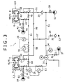
- Fig. 3 shows a schematic view of a vulcanization system for heating the bladders B from the inside.
- Fig. 3 shows two sets of lower and upper molds 2, 3 opened and closed by one open/close device.
- the same-type green tires G are respectively placed in cavities formed by the lower and upper molds 2, 3.
- the left center mechanism 4 is referred to as the center mechanism 4L
- the right center mechanism 4 is referred to as the center mechanism 4R.
- the tire vulcanizer 1 has a medium circulating passage 51 for circulating a nitrogen gas (vulcanization gas) clockwise upon preliminarily increasing a temperature of the nitrogen gas to a predetermined temperature before vulcanization and patterning.
- a nitrogen gas vulcanization gas
- a high-pressure nitrogen gas is supplied from a high-pressure gas supply port 12 to the medium circulating passage 51.
- a pressure control valve 26 for adjusting vulcanization pressure is provided in the medium circulating passage 51.
- a pump 10 for pressurizing the nitrogen gas is provided in the medium circulating passage 51.
- a check valve 20 for preventing a reverse flow of the nitrogen gas is provided.
- Industrial water for cooling a bearing of the pump 10 is supplied from a supply port 27 to the pump 10.
- Supply of the industrial water from the supply port 27 is controlled by a control valve 21.
- a temperature sensor 24 is provided in the bearing of the pump 10. The temperature sensor 24 monitors a temperature of the bearing of the pump 10. When the temperature detected by the temperature sensor 24 is higher than a predetermined temperature, the control valve 21 supplies the industrial water from the supply port 27 to the bearing of the pump 10, so as to cool the bearing of the pump 10.
- the tire vulcanizer 1 has medium supplying passages 52, 62 respectively provided for the center mechanisms 4L, 4R and connected to the medium circulating passage 51, the medium supplying passages for supplying the nitrogen gas circulated in the medium circulating passage 51 to the interiors of the bladders B.
- the other end of the medium supplying passage 52 whose one end is connected to the medium circulating passage 51 is connected to the fluid inlet 5 of the center mechanism 4L (refer to Fig. 1 ).
- the other end of the medium supplying passage 62 whose one end is connected to the medium circulating passage 51 is connected to the fluid inlet 5 of the center mechanism 4R (refer to Fig. 1 ).
- a supply switching automatic valve 13 is provided in the medium supplying passage 52.
- a supply switching automatic valve 43 is provided in the medium supplying passage 62.
- the tire vulcanizer 1 has medium returning passages 53, 63 respectively provided for the center mechanisms 4L, 4R and connected to the medium circulating passage 51, the medium returning passages for recovering the nitrogen gas discharged from the interiors of the bladders B to the medium circulating passage 51.
- the other end of the medium returning passage 53 whose one end is connected to the medium circulating passage 51 is connected to the fluid outlet 6 of the center mechanism 4L (refer to Fig. 1 ).
- the other end of the medium returning passage 63 whose one end is connected to the medium circulating passage 51 is connected to the fluid outlet 6 of the center mechanism 4R (refer to Fig. 1 ).
- the medium returning passages 53, 63 are connected to the medium circulating passage 51 on the downstream side in the circulating direction of the nitrogen gas with respect to the medium supplying passages 52, 62. Specifically, the medium returning passage 53 is connected to the medium circulating passage 51 on the downstream side in the circulating direction of the nitrogen gas with respect to the medium supplying passage 52. Similarly, the medium returning passage 63 is connected to the medium circulating passage 51 on the downstream side in the circulating direction of the nitrogen gas with respect to the medium supplying passage 62.
- An exhaust switching automatic valve 17 is provided in the medium returning passage 53.
- An exhaust switching automatic valve 47 is provided in the medium returning passage 63.
- the tire vulcanizer 1 has a first heating device 11 provided in the medium circulating passage 51, for heating the nitrogen gas.
- the first heating device 11 is arranged on the upstream side of a point where the medium supplying passage 52 provided in the center mechanism 4L which is placed on the upstream side in the circulating direction of the nitrogen gas is connected to the medium circulating passage 51.
- the high-pressure nitrogen gas supplied from the high-pressure gas supply port 12 passes through the medium circulating passage 51, and is further pressurized by the pump 10, and then heated in the first heating device 11.
- a temperature sensor 25 for measuring a temperature of the nitrogen gas is provided in an outlet of the first heating device 11.
- the first heating device 11 controls an output of the first heating device 11 based on the temperature measured by the temperature sensor 25 in such a manner that the temperature of the nitrogen gas at the outlet of the first heating device 11 becomes constant.
- bypass automatic valves 18, 48 are provided in the medium circulating passage 51.
- the bypass automatic valve 18 is arranged between a point where the medium supplying passage 52 is connected to the medium circulating passage 51 and a point where the medium returning passage 53 is connected to the medium circulating passage 51.
- the bypass automatic valve 48 is arranged between a point where the medium supplying passage 62 is connected to the medium circulating passage 51 and a point where the medium returning passage 63 is connected to the medium circulating passage 51.
- the nitrogen gas is circulated in the medium circulating passage 51.
- the bypass automatic valves 18, 48 are closed and the supply switching automatic valves 13, 43 and the exhaust switching automatic valves 17, 47 are opened, the nitrogen gas circulated in the medium circulating passage 51 is supplied to the interior of the bladder B of the left center mechanism 4L through the medium supplying passage 52.
- the nitrogen gas discharged from the interior of the bladder B of the left center mechanism 4L is recovered to the medium circulating passage 51 through the medium returning passage 53.
- the nitrogen gas recovered to the medium circulating passage 51 is supplied to the interior of the bladder B of the right center mechanism 4R through the medium supplying passage 62.
- the nitrogen gas discharged from the interior of the bladder B of the right center mechanism 4R is recovered to the medium circulating passage 51 through the medium returning passage 63 and recovered to the pump 10 through the check valve 20.
- the tire vulcanizer 1 has a second heating device 31 provided in the medium circulating passage 51, for heating the nitrogen gas.
- the second heating device 31 is arranged between a point where the medium returning passage 53 provided in the center mechanism 4L which is placed on the upstream side in the circulating direction of the nitrogen gas is connected to the medium circulating passage 51 and a point where the medium supplying passage 62 provided in the center mechanism 4R which is placed on the downstream side in the circulating direction of the nitrogen gas is connected to the medium circulating passage 51.
- a temperature sensor 28 for measuring the temperature of the gas is provided in an outlet of the second heating device 31.
- the second heating device 31 controls an output of the second heating device 31 based on the temperature measured by the temperature sensor 28 in such a manner that the temperature of the gas at the outlet of the second heating device 31 becomes constant.
- a medium supplying path 55 through which a low-pressure nitrogen gas supplied from a low-pressure gas supply port 14 passes is connected to the medium supplying passage 52.
- a decompression valve 15 and an automatic switch valve 16 are provided in this order in the medium supplying path 55 along the supplying direction of the low-pressure nitrogen gas.
- the decompression valve 15 adjusts pressure of the low-pressure nitrogen gas supplied from the low-pressure gas supply port 14. In a case where the supply switching automatic valve 13 is closed and the automatic switch valve 16 is opened, the low-pressure nitrogen gas supplied from the low-pressure gas supply port 14 is fed to the medium supplying passage 52 through the medium supplying path 55, and supplied to the interior of the bladder B of the left center mechanism 4L.
- a medium supplying path 65 through which a low-pressure nitrogen gas supplied from a low-pressure gas supply port 44 passes is connected to the medium supplying passage 62.
- a decompression valve 45 and an automatic switch valve 46 are provided in this order in the medium supplying path 65 along the supplying direction of the low-pressure nitrogen gas.
- the decompression valve 45 adjusts pressure of the low-pressure nitrogen gas supplied from the low-pressure gas supply port 44. In a case where the supply switching automatic valve 43 is closed and the automatic switch valve 46 is opened, the low-pressure nitrogen gas supplied from the low-pressure gas supply port 44 is fed to the medium supplying passage 62 through the medium supplying path 65, and supplied to the interior of the bladder B of the right center mechanism 4R.
- the tire vulcanizer 1 has medium exhausting passages 56, 66, 57 for exhausting the nitrogen gas discharged from the interiors of the bladders B to an exterior.
- the medium exhausting passage 56 branches from the medium returning passage 53.
- the medium exhausting passage 66 branches from the medium returning passage 63.
- the medium exhausting passage 56 and the medium exhausting passage 66 merge into the medium exhausting passage 57.
- An exhausting automatic valve 19 is provided in the medium exhausting passage 57, and the nitrogen gas passing through the exhausting automatic valve 19 is discharged from an exhaust port 23 to the exterior through a check valve 22 for preventing a reverse flow.
- a large number of tire vulcanizers 1 are installed in a tire factory, and main pipes are provided for utility of these tire vulcanizers 1.
- the high-pressure gas supply port 12, the low-pressure gas supply port 14, and the low-pressure gas supply port 44 shown in Fig. 3 are connection ports to the main pipes in the factory.
- the vulcanization and the patterning of the tires are started after the lower and upper molds 2, 3, the bladders B, and the like are sufficiently preliminarily heated. There is also a need for preliminarily increasing (preliminarily heating) the temperature of the nitrogen gas circulated in the medium circulating passage 51 to a predetermined temperature. Firstly, the supply switching automatic valves 13, 43 and the exhaust switching automatic valves 17, 47 are closed and the bypass automatic valves 18, 48 are opened. In this state, the pump 10 is rotated, and the first heating device 11 and the second heating device 31 provided in the medium circulating passage 51 are operated.
- the nitrogen gas supplied from the high-pressure gas supply port 12 is circulated in the medium circulating passage 51 by the pump 10, and in the meantime, heated to the predetermined temperature in the first heating device 11 and the second heating device 31.
- the control valve 21 controls supply of cooling water (industrial water) in such a manner that the temperature of the bearing of the pump 10 is not increased to the predetermined temperature or more.
- the green tires G are gripped by the installation devices 100 and loaded onto the lower molds 2 in the center mechanisms 4 (4L, 4R).
- the center mechanisms 4 (4L, 4R) As shown in Fig. 3 , in the left center mechanism 4L, the low-pressure nitrogen gas is supplied from the medium supplying path 55 to the interior of the bladder B.
- the automatic switch valve 16 is opened and the low-pressure nitrogen gas from the low-pressure gas supply port 14 is supplied to the interior of the bladder B via the decompression valve 15 and the automatic switch valve 16.
- the low-pressure nitrogen gas is supplied from the medium supplying path 65 to the interior of the bladder B.
- the automatic switch valve 46 is opened and the low-pressure nitrogen gas from the low-pressure gas supply port 44 is supplied to the interior of the bladder B via the decompression valve 45 and the automatic switch valve 46.
- the bladders B are extended in the center mechanisms 4L, 4R, and the bladders B are closely attached to the inner circumferential surfaces of the green tires G.
- the pressure of the low-pressure nitrogen gas is individually controlled by the decompression valves 15, 45 respectively provided in the medium supplying paths 55, 65.
- the installation devices 100 are retreated from the lower molds 2. After that, as shown in Fig. 2 , the upper molds 3 are lowered and the lower molds 2 and the upper molds 3 are closed, so that the squeezing force is generated between the lower and upper molds 2, 3. As shown in Fig. 3 , the automatic switch valves 16, 46 are respectively closed. The supply switching automatic valves 13, 43, the exhaust switching automatic valves 17, 47 are opened, and the bypass automatic valves 18, 48 are closed.
- the vulcanization and the patterning are started. Immediately after start of the vulcanization and the patterning, the nitrogen gas which has been circulated in the medium circulating passage 51 is supplied to the interior of the bladder B of the left center mechanism 4L through the medium supplying passage 52. At this time, since a capacity of the interior of the bladder B is large, pressure of the closed circuit is lowered immediately after the start of the vulcanization and the patterning. When the pressure of the closed circuit is lowered, the normal-temperature and high-pressure nitrogen gas is supplemented into the closed circuit from the high-pressure gas supply port 12. This nitrogen gas is pressurized by the pump 10, heated in the first heating device 11, and supplied to the interior of the bladder B of the left center mechanism 4L.
- the nitrogen gas discharged from the interior of the bladder B of the left center mechanism 4L is used for the vulcanization and the patterning, so that the temperature thereof is lowered. However, the nitrogen gas is heated again in the second heating device 31 and then supplied to the interior of the bladder B of the right center mechanism 4R. Until the pressure of the closed circuit reaches predetermined pressure, the high-pressure nitrogen gas continues to be supplied from the high-pressure gas supply port 12.
- the pressure control valve 26 provided between the high-pressure gas supply port 12 and the medium circulating passage 51 controls the pressure in such a manner that the pressure of the closed circuit becomes the predetermined pressure. It should be noted that the vulcanization of the tires largely depends on the temperature but does not largely depend on the pressure. Thus, without using the pressure control valve 26, the high-pressure nitrogen gas may be supplied directly from the main pipe whose pressure is controlled. A flow of the nitrogen gas in the reverse direction of the closed circuit is suppressed by the check valve 20.
- the pump 10 has a capability of generating differential pressure of about 0.1 MPa to 0.2 MPa between an inlet and an outlet at a flow rate of about 1 m 3 in order to circulate the nitrogen gas, and acts as a pressurization and circulation device for pressurizing and circulating the nitrogen gas on the inlet side.
- the system is designed in such a manner that a pressure loss of the nitrogen gas circulated in the closed circuit becomes the differential pressure generation capability of the pump 10 or less, without newly supplying the high-pressure nitrogen gas from the exterior, the nitrogen gas is circulated in the closed circuit at the predetermined pressure.
- the nitrogen gas circulated in the closed circuit is firstly heated in the first heating device 11.
- the temperature of the nitrogen gas on the outlet side of the first heating device 11 is maintained to be constant.
- the temperature of the nitrogen gas on the outlet side of the first heating device 11 is radically lowered.
- the first heating device 11 increases the output and heats the nitrogen gas with a full output, and lowers the output in accordance with an increase in the temperature of the nitrogen gas on the outlet side.
- the nitrogen gas heated in the first heating device 11 is supplied to the interior of the bladder B of the left center mechanism 4L placed on the upstream side in the circulating direction of the nitrogen gas. Thereby, in the lower and upper molds 2, 3 on the side of the left center mechanism 4L, the vulcanization and the patterning of the green tire G are performed.
- the nitrogen gas discharged from the interior of the bladder B of the left center mechanism 4L is used for the vulcanization and the patterning, so that the temperature thereof is lowered. However, this nitrogen gas is heated again in the second heating device 31, so that the temperature is increased.
- the temperature of the nitrogen gas on the outlet side of the second heating device 31 is maintained to be constant. Therefore, the nitrogen gas heated in the second heating device 31 is supplied to the interior of the bladder B of the right center mechanism 4R placed on the downstream side in the circulating direction of the nitrogen gas. Thereby, in the lower and upper molds 2, 3 on the side of the right center mechanism 4R, the vulcanization and the patterning of the green tire G are performed.
- the nitrogen gas discharged from the interior of the bladder B of the right center mechanism 4R is used for the vulcanization and the patterning, so that the temperature thereof is lowered. However, this nitrogen gas is supplied again to the pump 10 and heated again in the first heating device 11, so that the temperature is increased. In such a way, the nitrogen gas is circulated in the closed circuit, and the vulcanization and the patterning are performed respectively in the two sets of lower and upper molds 2, 3.
- the bypass automatic valves 18, 48 are opened, the supply switching automatic valves 13, 43 and the exhaust switching automatic valves 17, 47 are closed, and the exhausting automatic valve 19 is opened.
- the nitrogen gas discharged from the interior of the bladder B of the left center mechanism 4L is discharged from the exhaust port 23 to the main pipe through the medium exhausting passage 56 and the medium exhausting passage 57
- the nitrogen gas discharged from the interior of the bladder B of the right center mechanism 4R is discharged from the exhaust port 23 to the main pipe through the medium exhausting passage 66 and the medium exhausting passage 57.
- the lower molds 2 and the upper molds 3 are opened, and the vulcanized tires are taken out from the lower and upper molds 2, 3, and carried out to the next step.
- the nitrogen gas fed out from the pump 10 at the time of completing the vulcanization and the patterning is fed to the second heating device 31 through the first heating device 11 and the bypass automatic valve 18, and further circulated in the medium circulating passage 51 serving as a passage to recover to the pump 10 through the bypass automatic valve 48.
- the first heating device 11 and the second heating device 31 respectively adjust the outputs in such a manner that the temperatures of the nitrogen gas on the outlet side become the predetermined temperature (are preliminarily heated).
- the nitrogen gas heated in the first heating device 11 is supplied to the interior of the bladder B of the left center mechanism 4L placed on the upstream side in the circulating direction of the nitrogen gas.
- the vulcanization and the patterning of the green tire G are performed.
- the nitrogen gas discharged from the interior of the bladder B of the left center mechanism 4L which is placed on the upstream side in the circulating direction of the nitrogen gas is used for the vulcanization and the patterning, so that the temperature thereof is lowered.
- this nitrogen gas is heated again in the second heating device 31, so that the temperature is increased. Therefore, the nitrogen gas heated in the second heating device 31 is supplied to the interior of the bladder B of the right center mechanism 4R placed on the downstream side in the circulating direction of the nitrogen gas. Thereby, in the lower and upper molds 2, 3 placed on the downstream side in the circulating direction of the nitrogen gas (on the side of the right center mechanism 4R), the vulcanization and the patterning of the green tire G are performed. The nitrogen gas discharged from the interior of the bladder B of the right center mechanism 4R which is placed on the downstream side in the circulating direction of the nitrogen gas is used for the vulcanization and the patterning, so that the temperature thereof is lowered.
- this nitrogen gas is heated again in the first heating device 11, so that the temperature is increased.
- the vulcanization and the patterning are respectively performed in the two sets of lower and upper molds 2, 3.
- the two green tires G can be respectively vulcanized and patterned with one system shared by the two center mechanisms 4L, 4R. Therefore, economical efficiency can be improved.
- the tire vulcanizer 201 of the second embodiment is different from the tire vulcanizer 1 of the first embodiment in a point that as shown in Fig. 4 , the tire vulcanizer has a tank 70 provided in the medium exhausting passage 57, for storing the nitrogen gas discharged from the interiors of the bladders B, and medium supplying paths 58, 59, 60 respectively provided for the center mechanisms 4L, 4R, for supplying the nitrogen gas in an interior of the tank 70 to the interiors of the bladders B.
- the nitrogen gas discharged from the interiors of the bladders B of the center mechanisms 4L, 4R passes through the medium exhausting passage 56 and the medium exhausting passage 66 and merges in the medium exhausting passage 57.
- the medium exhausting passage 57 branches into a passage through which the gas is discharged from the exhaust port 23 to the exterior through an automatic switch valve 29 and the check valve 22, and a passage through which the gas flows to the interior of the tank 70 through an automatic switch valve 72.
- the nitrogen gas discharged from the interior of the tank 70 passes through an automatic exhaust valve 71 and is discharged from the same exhaust port 23 from which the nitrogen gas passing through the automatic switch valve 29 and the check valve 22 is also discharged to the exterior.
- the automatic exhaust valve 71 is closed at the time of the vulcanization and the patterning, and opened at the time of stop of the tire vulcanizer 201, so as to discharge the nitrogen gas in the interior of the tank 70 to the exterior.
- Pressure sensors 74, 75 are respectively provided at a point where the medium exhausting passage 56 and the medium exhausting passage 66 merge and at an outlet of the tank 70.
- the automatic switch valve 72 is closed and the automatic switch valve 29 is opened.
- the nitrogen gas discharged from interiors of the bladders B is discharged from the exhaust port 23 to the exterior through the automatic switch valve 29 and the check valve 22.
- the automatic switch valve 29 is closed and the automatic switch valve 72 is opened.
- the nitrogen gas discharged from the interiors of the bladders B is stored in the interior of the tank 70.
- the low-pressure gas supply port 14 is connected to the medium supplying path 55 via the medium supplying path 58, and also connected to the medium supplying path 65 via the medium supplying path 59 and the medium supplying path 60.
- a switch valve 76 is provided on the side of the low-pressure gas supply port 14 with respect to a point where the medium supplying path 59 is connected to the medium supplying path 58.
- the low-pressure nitrogen gas from the low-pressure gas supply port 14 is supplied to the interior of the bladder B of the left center mechanism 4L through the medium supplying path 58 and the medium supplying path 55, and also supplied to the interior of the bladder B of the right center mechanism 4R through the medium supplying path 59, the medium supplying path 60, and the medium supplying path 65.
- the nitrogen gas in the interior of the tank 70 is supplied to the interior of the bladder B of the left center mechanism 4L through the medium supplying path 59, the medium supplying path 58, and the medium supplying path 55, and also supplied to the interior of the bladder B of the right center mechanism 4R through the medium supplying path 60 and the medium supplying path 65.
- the medium circulating passage 51 is arranged around the tank 70.
- the nitrogen gas in the interior of the tank 70 is heated with the nitrogen gas circulated in the medium circulating passage 51. Thereby, a decrease in the temperature of the nitrogen gas in the interior of the tank 70 is prevented.
- the high-pressure nitrogen gas supplied from the high-pressure gas supply port 12 is circulated in the medium circulating passage 51 by the pump 10, and in the meantime, heated to the predetermined temperature in the first heating device 11 and the second heating device 31.
- the tank 70 is in a non-pressure state.
- the switch valve 76 is opened.
- the left center mechanism 4L the normal-temperature and low-pressure nitrogen gas is supplied from the low-pressure gas supply port 14 to the interior of the bladder B through the medium supplying path 58 and the medium supplying path 55.
- the normal-temperature and low-pressure nitrogen gas is supplied from the low-pressure gas supply port 14 to the interior of the bladder B through the medium supplying path 59, the medium supplying path 60, and the medium supplying path 65.
- the bladders B are extended, so that the bladders B are closely attached to the inner circumferential surfaces of the green tires G.
- the low-pressure gas supply port 14 is generally unused but supplies the low-pressure nitrogen gas only in a case where the interior of the tank 70 is in a non-pressure state.
- the upper molds 3 and the lower molds 2 are closed.
- the bypass automatic valves 18, 48 and opening the supply switching automatic valves 13, 43 and the exhaust switching automatic valves 17, 47 the closed circuit running from the medium circulating passage 51, the medium supplying passage 52, the interior of the bladder B of the left center mechanism 4L, the medium returning passage 53, the medium circulating passage 51, the medium supplying passage 62, the interior of the bladder B of the right center mechanism 4R, the medium returning passage 63, to the medium circulating passage 51 is formed, and the high-pressure nitrogen gas is circulated, so that the vulcanization and the patterning are performed.
- the bypass automatic valves 18, 48 are opened, and the supply switching automatic valves 13, 43 and the exhaust switching automatic valves 17, 47 are closed.
- the automatic switch valve 29 is closed and the automatic switch valve 72 is opened.
- the high-pressure nitrogen gas discharged from the interiors of the bladders B passes through the medium exhausting passage 56, the medium exhausting passage 66, and the medium exhausting passage 57 and is stored in the interior of the tank 70.
- the nitrogen gas does not flow through the medium exhausting passages 56, 66, 57.
- the automatic switch valve 72 is closed and the automatic switch valve 29 is opened, so that the nitrogen gas remaining in the interiors of the bladders B is exhausted from the exhaust port 23 to the exterior.
- the pressure difference between the pressure sensors 74, 75 at the time of switching between the automatic switch valve 72 and the automatic switch valve 29 is preferably 0.01 to 0.03 MPa.
- the bladders B are extended with the nitrogen gas stored in the interior of the tank 70 instead of the low-pressure nitrogen gas from the low-pressure gas supply port 14.
- the nitrogen gas in the interior of the tank 70 is supplied to the interior of the bladder B through the medium supplying path 59, the medium supplying path 58, and the medium supplying path 55.
- the nitrogen gas in the interior of the tank 70 is supplied to the interior of the bladder B through the medium supplying path 60 and the medium supplying path 65. At this time, the pressure of the nitrogen gas is decompressed by the decompression valves 15, 45 and supplied to the interiors of the bladders B.
- the pressure of the high-pressure nitrogen gas is about 2 MPa, and the pressure required for the shaping is about 0.01 to 0.02 MPa.
- the bladders B are extended, so that the bladders B are closely attached to the inner circumferential surfaces of the green tires G.
- thermal energy and pressure energy remaining in the tire vulcanizer 201 can be reused, and a supply amount of the low-pressure nitrogen gas supplied from the low-pressure gas supply port 14 can be decreased.
- the nitrogen gas discharged from the interiors of the bladders B is collected into the interior of the tank 70.
- the nitrogen gas discharged from the interior of the bladder B is collected into the interior of the tank 70 through the medium returning passage 53, the medium exhausting passage 56, and the medium exhausting passage 57.
- the nitrogen gas discharged from the interior of the bladder B is collected into the interior of the tank 70 through the medium returning passage 63, the medium exhausting passage 66, and the medium exhausting passage 57.
- the upper molds 3 and the lower molds 2 are closed and the vulcanization and the patterning are started.
- the pressure of the closed circuit is lowered. Therefore, in the first embodiment, the normal-temperature and high-pressure nitrogen gas is supplemented into the closed circuit from the high-pressure gas supply port 12.
- the automatic switch valve 29 is closed and the automatic switch valve 72 is opened, so that the nitrogen gas in the interior of the tank 70 is supplied to the interiors of the bladders B. It should be noted that by closing the supply switching automatic valves 13, 43 and the exhaust switching automatic valves 17, 47 and opening the bypass automatic valves 18, 48, a high-temperature and high-pressure nitrogen gas is circulated in the medium circulating passage 51.
- the nitrogen gas in the interior of the tank 70 is supplied to the interior of the bladder B through the medium supplying path 59, the medium supplying path 58, and the medium supplying path 55.
- the nitrogen gas in the interior of the tank 70 is supplied to the interior of the bladder B through the medium supplying path 60 and the medium supplying path 65.
- the thermal energy and the pressure energy remaining in the tire vulcanizer 201 can be reused, and a supply amount of the high-pressure nitrogen gas supplemented from the high-pressure gas supply port 12 can be decreased, so that thermal energy for heating the supplemented nitrogen gas can be decreased.
- a temperature of the interiors of the bladders B can be promptly increased, so that a vulcanization time can be shortened.
- the nitrogen gas discharged from the interiors of the bladders B is collected into the tank 70.
- the nitrogen gas discharged from the interior of the bladder B is collected into the interior of the tank 70 through the medium returning passage 53, the medium exhausting passage 56, and the medium exhausting passage 57.
- the nitrogen gas discharged from the interior of the bladder B is collected into the interior of the tank 70 through the medium returning passage 63, the medium exhausting passage 66, and the medium exhausting passage 57.
- the vulcanization and the patterning are performed with the nitrogen gas circulated in the medium circulating passage 51.
- the closed circuit is formed, and the high-temperature and high-pressure nitrogen gas is circulated in the closed circuit.
- the bypass automatic valves 18, 48 are opened again, and the supply switching automatic valves 13, 43 and the exhaust switching automatic valves 17, 47 are closed.
- the automatic switch valve 29 is closed and the automatic switch valve 72 is opened, so that the nitrogen gas discharged from the interiors of the bladders B is stored in the interior of the tank 70.
- the automatic switch valve 72 is closed and the automatic switch valve 29 is opened, so that the nitrogen gas remaining in the interiors of the bladders B is exhausted from the exhaust port 23 to the exterior.
- the thermal energy and the pressure energy remaining in the tire vulcanizer 201 are reused at the time of the shaping.
- the thermal energy and the pressure energy remaining in the tire vulcanizer 201 at the beginning of the vulcanization and the patterning are reused. It should be noted that the energy may be reused at the time of the shaping or at the beginning of the vulcanization and the patterning.
- the energy to be reused is determined in accordance with a capacity of the tank 70.
- the energy of the pump 10, the first heating device 11, and the second heating device 31, which is required for vulcanizing one tire can be saved by about 3%.
- An amount of the high-pressure nitrogen gas supplied from the main pipe via the high-pressure gas supply port 12 is decreased by about 30%.
- a facility for generating the high-pressure nitrogen gas can be downsized.
- the high-temperature nitrogen gas in the interior of the tank 70 can be supplied to the interiors of the bladders B at the beginning of the vulcanization.
- the temperature of the interiors of the bladders B can be promptly increased, so that the vulcanization time can also be shortened.
- the nitrogen gas is generally exhausted through the medium exhausting passage 57 after the completion of the vulcanization, the thermal energy and the pressure energy remaining in the tire vulcanizer 201 at the time of completing the vulcanization are released to the exterior of the tire vulcanizer 201, so that energy efficiency is unfavorable.
- the nitrogen gas discharged from the interiors of the bladders B is stored in the interior of the tank 70.
- the nitrogen gas stored in the interior of the tank 70 is supplied to the interiors of the bladders B at the time of the shaping.
- the bladders B are extended with the low-pressure nitrogen gas supplied from the low-pressure gas supply port 14 at the time of the shaping.
- the bladders B are extended with the nitrogen gas stored in the interior of the tank 70 instead of the low-pressure nitrogen gas. In such a way, by extending the bladders B with the nitrogen gas stored in the interior of the tank 70, the thermal energy and the pressure energy remaining in the tire vulcanizer 201 can be reused, and the supply amount of the low-pressure nitrogen gas supplied from the low-pressure gas supply port 14 can be decreased.
- the nitrogen gas stored in the interior of the tank 70 is supplied to the interiors of the bladders B at the beginning of the vulcanization and the patterning.
- the vulcanization and the patterning are performed with the high-temperature and high-pressure nitrogen gas circulated in the medium circulating passage 51.
- the pressure of the nitrogen gas is lowered at the beginning of the vulcanization and the patterning, there is a need for supplementing the high-pressure nitrogen gas from the high-pressure gas supply port 12 and heating the supplemented nitrogen gas.
- the thermal energy and the pressure energy remaining in the tire vulcanizer 201 can be reused, and the supply amount of the high-pressure nitrogen gas supplemented from the high-pressure gas supply port 12 can be decreased, so that the thermal energy for heating the supplemented nitrogen gas can be decreased.
- the high-temperature nitrogen gas stored in the interior of the tank 70 at the beginning of the vulcanization and the patterning the temperature of the interiors of the bladders B can be promptly increased, so that the vulcanization time can be shortened. Thereby, the energy efficiency can be improved.
- a nitrogen gas heated in a first heating device is supplied to an interior of the bladder of the center mechanism which is placed on the upstream side in the circulating direction of the nitrogen gas.
- the nitrogen gas discharged from the interior of the bladder of the center mechanism is used for vulcanization and patterning and a temperature thereof is lowered.
- this nitrogen gas is heated again in a second heating device, so that the temperature is increased. Therefore, the nitrogen gas heated in the second heating device is supplied to an interior of the bladder of the center mechanism which is placed on the downstream side in the circulating direction of the nitrogen gas.
Landscapes
- Engineering & Computer Science (AREA)
- Mechanical Engineering (AREA)
- Physics & Mathematics (AREA)
- Health & Medical Sciences (AREA)
- Oral & Maxillofacial Surgery (AREA)
- Thermal Sciences (AREA)
- Heating, Cooling, Or Curing Plastics Or The Like In General (AREA)
- Moulds For Moulding Plastics Or The Like (AREA)
Abstract
Description
- The present invention relates to a tire vulcanizer for squeezing upper molds and lower molds so as to vulcanize and pattern green tires, and a tire vulcanizing method.
- In a manufacturing step of a tire, a green tire made by assembling constituent members of the tire is vulcanized by a tire vulcanizer. A bladder to be inflated by a low-pressure pressure medium is closely attached to an inner circumferential surface of the green tire installed between openable and closable upper and lower molds by a center mechanism of the tire vulcanizer. After that, the green tire is heated from inside by squeezing of the upper and lower molds and introduction of a high-pressure heating medium to an interior of the bladder. The upper and lower molds are always heated by platen, the green tire is vulcanized by heating from an inner surface and an outer surface thereof.
- There are various types of tire vulcanizers used in a vulcanization step. Japanese Unexamined Patent Application Publication No.
H9-239734 - Japanese Unexamined Patent Application Publication No.
2008-162269 - A temperature of the high-pressure nitrogen gas circulated in the medium circulating passage is increased to a predetermined temperature. In this state, when upper and lower molds are closed and a squeezing force is imposed between the upper and lower molds, communication between the medium circulating passage, and the medium supplying passage and the medium returning passage is provided by the valve operation, so that the vulcanization is performed. The preliminarily heated high-pressure nitrogen gas is supplied to the interior of the bladder through the medium supplying passage. The nitrogen gas discharged from the interior of the bladder is recovered to the medium circulating passage through the medium returning passage.
- In the tire vulcanizer of Japanese Unexamined Patent Application Publication No.
2008-162269 H9-239734 2008-162269 - An object of the present invention is to provide a tire vulcanizer capable of improving economical efficiency in a twin type tire vulcanizer, and a tire vulcanizing method.
- A tire vulcanizer in the present invention includes two sets of vulcanizing and patterning portions, each of which includes a lower mold, an upper mold openable and closable relative to the lower mold, and a center mechanism provided with a bladder to be installed in a green tire, the vulcanizing and patterning portions for squeezing the green tires with the lower molds and the upper molds after shaping of installing the bladders to the green tires, so as to perform vulcanization and patterning, a medium circulating passage for circulating a vulcanization gas, medium supplying passages respectively provided for the center mechanisms and connected to the medium circulating passage, the medium supplying passages for supplying the vulcanization gas circulated in the medium circulating passage to interiors of the bladders, medium returning passages respectively provided for the center mechanisms and connected to the medium circulating passage on the downstream side in the circulating direction of the vulcanization gas with respect to the medium supplying passages, the medium returning passages for recovering the vulcanization gas discharged from the interiors of the bladders to the medium circulating passage, a pump provided in the medium circulating passage, for pressurizing the vulcanization gas, supply switching valves respectively provided in the medium supplying passages, for opening and closing the medium supplying passages, exhaust switching valves respectively provided in the medium returning passages, for opening and closing the medium returning passages, bypass valves provided in the medium circulating passage and respectively arranged for the center mechanisms between a point where the medium supplying passages are connected to the medium circulating passage and a point where the medium returning passages are connected to the medium circulating passage, the bypass valves for opening and closing the medium circulating passage, a first heating device provided in the medium circulating passage and arranged on the upstream side with respect to a point where the medium supplying passage provided in the center mechanism which is placed on the upstream side in the circulating direction of the vulcanization gas is connected to the medium circulating passage, the first heating device for heating the vulcanization gas, and a second heating device provided in the medium circulating passage and arranged between a point where the medium returning passage provided in the center mechanism which is placed on the upstream side in the circulating direction of the vulcanization gas is connected to the medium circulating passage, and a point where the medium supplying passage provided in the center mechanism which is placed on the downstream side in the circulating direction of the vulcanization gas is connected to the medium circulating passage, the second heating device for heating the vulcanization gas.
- According to the above configuration, the vulcanization gas heated in the first heating device is supplied to the interior of the bladder of the center mechanism which is placed on the upstream side in the circulating direction of the vulcanization gas. Thereby, the vulcanization and the patterning of the green tire are performed in the upper and lower molds placed on the upstream side in the circulating direction of the vulcanization gas. The vulcanization gas discharged from the interior of the bladder of the center mechanism which is placed on the upstream side in the circulating direction of the vulcanization gas is used for the vulcanization and the patterning, so that a temperature thereof is lowered. However, this vulcanization gas is heated again in the second heating device, so that the temperature is increased. Therefore, the vulcanization gas heated in the second heating device is supplied to the interior of the bladder of the center mechanism which is placed on the downstream side in the circulating direction of the vulcanization gas. Thereby, the vulcanization and the patterning of the green tire are performed in the upper and lower molds placed on the downstream side in the circulating direction of the vulcanization gas. The vulcanization gas discharged from the interior of the bladder of the center mechanism which is placed on the downstream side in the circulating direction of the vulcanization gas is used for the vulcanization and the patterning, so that the temperature thereof is lowered. However, this vulcanization gas is heated again in the first heating device, so that the temperature is increased. In such a way, the vulcanization and the patterning are respectively performed in the two sets of upper and lower molds. In this manner, even when systems for circulating the vulcanization gas are not respectively provided for the center mechanisms, two green tires can be respectively vulcanized and patterned with one system shared by the two center mechanisms. Therefore, the economical efficiency can be improved.
- The tire vulcanizer in the present invention further includes medium exhausting passages for exhausting the vulcanization gas discharged from the interiors of the bladders to an exterior, a tank provided in the medium exhausting passage, for storing the vulcanization gas discharged from the interiors of the bladders, and medium supplying paths respectively provided for the center mechanisms, for supplying the vulcanization gas in an interior of the tank to the interiors of the bladders, wherein at the time of at least one of the shaping and beginning of the vulcanization and the patterning, the vulcanization gas in the interior of the tank is supplied to the interiors of the bladders via the medium supplying paths.
- According to the above configuration, since the vulcanization gas is generally exhausted through the medium exhausting passages after completion of the vulcanization, thermal energy and pressure energy remaining in the tire vulcanizer are released to the exterior of the tire vulcanizer at the time of the completion of the vulcanization, so that energy efficiency is unfavorable. Thus, the vulcanization gas discharged from the interiors of the bladders is stored in the interior of the tank. The vulcanization gas stored in the interior of the tank is supplied to the interiors of the bladders at the time of the shaping. In general, the bladders are extended with a low-pressure gas supplied from a low-pressure gas supply source at the time of the shaping. However, the bladders are extended with the vulcanization gas stored in the interior of the tank instead of the low-pressure gas. In such a way, by extending the bladders with the vulcanization gas stored in the interior of the tank, the thermal energy and the pressure energy remaining in the tire vulcanizer can be reused, and a supply amount of the low-pressure gas supplied from the low-pressure gas supply source can be decreased. The vulcanization gas stored in the interior of the tank is supplied to the interiors of the bladders at the beginning of the vulcanization and the patterning. In general, the vulcanization and the patterning are performed with a high-temperature and high-pressure vulcanization gas circulated in the medium circulating passage. However, since pressure of the vulcanization gas is lowered at the beginning of the vulcanization and the patterning, there is a need for supplementing a high-pressure vulcanization gas from a vulcanization gas supply source and heating the supplemented vulcanization gas. In this regard, by using the vulcanization gas stored in the interior of the tank at the beginning of the vulcanization and the patterning, the thermal energy and the pressure energy remaining in the tire vulcanizer can be reused, and a supply amount of the high-pressure vulcanization gas supplemented from the vulcanization gas supply source can be decreased, so that thermal energy for heating the supplemented vulcanization gas can be decreased. By using the high-temperature vulcanization gas stored in the interior of the tank at the beginning of the vulcanization and the patterning, a temperature of the interiors of the bladders can be promptly increased, so that a vulcanization time can be shortened. Thereby, energy efficiency can be improved.
- A tire vulcanizing method in the present invention is a tire vulcanizing method performed by using the tire vulcanizer, including a step of circulating the vulcanization gas in the medium circulating passage by the pump while closing the supply switching valves and the exhaust switching valves, opening the bypass valves, and heating the vulcanization gas by using at least one of the first heating device and the second heating device, and a step of supplying the vulcanization gas to the interiors of the bladders by the medium supplying passages while opening the supply switching valves and the exhaust switching valves, closing the bypass valves, and heating the vulcanization gas by using the first heating device and the second heating device, and recovering the vulcanization gas discharged from the interiors of the bladders to the medium circulating passage by the medium returning passages, so as to vulcanize and pattern the tires.
- According to the tire vulcanizer and the tire vulcanizing method of the present invention, even when systems for circulating the vulcanization gas are not respectively provided for the center mechanisms, two green tires can be respectively vulcanized and patterned with one system shared by the two center mechanisms. Therefore, the economical efficiency can be improved.
-
-
Fig. 1 is a sectional view showing a tire vulcanizer; -
Fig. 2 is a sectional view showing the tire vulcanizer; -
Fig. 3 is a schematic view showing the tire vulcanizer; and -
Fig. 4 is a schematic view showing a tire vulcanizer. - Hereinafter, preferred embodiments of the present invention will be described with reference to the drawings.
- A
tire vulcanizer 1 according to the present embodiment has lower andupper molds Fig. 1 . The green tire G is patterned and formed by connecting and attaching constituent members such as a bead, a tread, and a side wall to each other in a patterning step. This green tire G is carried to a vulcanization step, and vulcanized and patterned in thetire vulcanizer 1. - The
lower mold 2 is replaceably provided on alower heat plate 7 serving as a heat source. Theupper mold 3 is replaceably provided under anupper heat plate 8 serving as a heat source. Ajacket 9 serving as a heat source is provided in a periphery of theupper mold 3. By moving theupper mold 3 upward and downward by an upper structure, theupper mold 3 is openable and closable from the upper side relative to thelower mold 2. As shown inFig. 1 , in a state that thelower mold 2 and theupper mold 3 are opened, the green tire G is carried onto thelower mold 2 by aninstallation device 100. - On the center lower side of the
lower mold 2, acenter mechanism 4 provided with an extendable and retractable bag shape bladder B which is made of an elastic material (such as butyl rubber) is arranged. Afluid inlet 5 for introducing a gas to an interior of the bladder B, and afluid outlet 6 for discharging the gas from the interior of the bladder B are provided in thecenter mechanism 4. By introducing a low-pressure nitrogen gas from thefluid inlet 5 to the interior of the bladder B, thecenter mechanism 4 extends the bladder B and closely attaches the bladder B to an inner circumferential surface of the green tire G carried onto thelower mold 2. This step is called a shaping step. - When the shaping step is completed, as shown in
Fig. 2 , the green tire G is vulcanized and patterned. That is, theinstallation device 100 is retreated from thelower mold 2. By lowering theupper mold 3, theupper mold 3 and thelower mold 2 are closed, so that a squeezing force is generated between the lower andupper molds fluid inlet 5 to the interior of the bladder B. Thereby, the green tire G is heated from inside and outside, so that the green tire G is vulcanized and patterned. - When the vulcanization and patterning step is completed, some vulcanized tires are cooled by a device called a post inflator in a state that the tires are inflated by air pressure in order to prevent deformation at the time of cooling, and further carried to the next step. Other vulcanized tires are left to be naturally cooled and carried to the next step.
-
Figs. 1 and2 show only one set of a vulcanization and patterning portion including the lower andupper molds center mechanism 4 provided with the bladder B. However, in thetire vulcanizer 1 of the present embodiment, two sets of vulcanization and patterning portions are arranged in parallel. -
Fig. 3 shows a schematic view of a vulcanization system for heating the bladders B from the inside.Fig. 3 shows two sets of lower andupper molds upper molds Fig. 3 , theleft center mechanism 4 is referred to as thecenter mechanism 4L, and theright center mechanism 4 is referred to as thecenter mechanism 4R. - The
tire vulcanizer 1 has amedium circulating passage 51 for circulating a nitrogen gas (vulcanization gas) clockwise upon preliminarily increasing a temperature of the nitrogen gas to a predetermined temperature before vulcanization and patterning. As the gas supplied to thetire vulcanizer 1, a highly-pure normal-temperature nitrogen gas which is chemically stable is generally used. A high-pressure nitrogen gas is supplied from a high-pressuregas supply port 12 to themedium circulating passage 51. Between themedium circulating passage 51 and the high-pressuregas supply port 12, apressure control valve 26 for adjusting vulcanization pressure is provided. In themedium circulating passage 51, apump 10 for pressurizing the nitrogen gas is provided. In themedium circulating passage 51, acheck valve 20 for preventing a reverse flow of the nitrogen gas is provided. - Industrial water for cooling a bearing of the
pump 10 is supplied from asupply port 27 to thepump 10. Supply of the industrial water from thesupply port 27 is controlled by acontrol valve 21. Atemperature sensor 24 is provided in the bearing of thepump 10. Thetemperature sensor 24 monitors a temperature of the bearing of thepump 10. When the temperature detected by thetemperature sensor 24 is higher than a predetermined temperature, thecontrol valve 21 supplies the industrial water from thesupply port 27 to the bearing of thepump 10, so as to cool the bearing of thepump 10. - The
tire vulcanizer 1 hasmedium supplying passages center mechanisms medium circulating passage 51, the medium supplying passages for supplying the nitrogen gas circulated in themedium circulating passage 51 to the interiors of the bladders B. Specifically, the other end of themedium supplying passage 52 whose one end is connected to themedium circulating passage 51 is connected to thefluid inlet 5 of thecenter mechanism 4L (refer toFig. 1 ). The other end of themedium supplying passage 62 whose one end is connected to themedium circulating passage 51 is connected to thefluid inlet 5 of thecenter mechanism 4R (refer toFig. 1 ). A supply switchingautomatic valve 13 is provided in themedium supplying passage 52. A supply switchingautomatic valve 43 is provided in themedium supplying passage 62. - The
tire vulcanizer 1 hasmedium returning passages center mechanisms medium circulating passage 51, the medium returning passages for recovering the nitrogen gas discharged from the interiors of the bladders B to themedium circulating passage 51. Specifically, the other end of themedium returning passage 53 whose one end is connected to themedium circulating passage 51 is connected to thefluid outlet 6 of thecenter mechanism 4L (refer toFig. 1 ). The other end of themedium returning passage 63 whose one end is connected to themedium circulating passage 51 is connected to thefluid outlet 6 of thecenter mechanism 4R (refer toFig. 1 ). Themedium returning passages medium circulating passage 51 on the downstream side in the circulating direction of the nitrogen gas with respect to themedium supplying passages medium returning passage 53 is connected to themedium circulating passage 51 on the downstream side in the circulating direction of the nitrogen gas with respect to themedium supplying passage 52. Similarly, themedium returning passage 63 is connected to themedium circulating passage 51 on the downstream side in the circulating direction of the nitrogen gas with respect to themedium supplying passage 62. An exhaust switchingautomatic valve 17 is provided in themedium returning passage 53. An exhaust switchingautomatic valve 47 is provided in themedium returning passage 63. - The
tire vulcanizer 1 has afirst heating device 11 provided in themedium circulating passage 51, for heating the nitrogen gas. Thefirst heating device 11 is arranged on the upstream side of a point where themedium supplying passage 52 provided in thecenter mechanism 4L which is placed on the upstream side in the circulating direction of the nitrogen gas is connected to themedium circulating passage 51. The high-pressure nitrogen gas supplied from the high-pressuregas supply port 12 passes through themedium circulating passage 51, and is further pressurized by thepump 10, and then heated in thefirst heating device 11. - A
temperature sensor 25 for measuring a temperature of the nitrogen gas is provided in an outlet of thefirst heating device 11. Thefirst heating device 11 controls an output of thefirst heating device 11 based on the temperature measured by thetemperature sensor 25 in such a manner that the temperature of the nitrogen gas at the outlet of thefirst heating device 11 becomes constant. - Bypass
automatic valves medium circulating passage 51. The bypassautomatic valve 18 is arranged between a point where themedium supplying passage 52 is connected to themedium circulating passage 51 and a point where themedium returning passage 53 is connected to themedium circulating passage 51. The bypassautomatic valve 48 is arranged between a point where themedium supplying passage 62 is connected to themedium circulating passage 51 and a point where themedium returning passage 63 is connected to themedium circulating passage 51. - In a case where the bypass
automatic valves automatic valves automatic valves medium circulating passage 51. Meanwhile, in a case where the bypassautomatic valves automatic valves automatic valves medium circulating passage 51 is supplied to the interior of the bladder B of theleft center mechanism 4L through themedium supplying passage 52. The nitrogen gas discharged from the interior of the bladder B of theleft center mechanism 4L is recovered to themedium circulating passage 51 through themedium returning passage 53. Further, the nitrogen gas recovered to themedium circulating passage 51 is supplied to the interior of the bladder B of theright center mechanism 4R through themedium supplying passage 62. The nitrogen gas discharged from the interior of the bladder B of theright center mechanism 4R is recovered to themedium circulating passage 51 through themedium returning passage 63 and recovered to thepump 10 through thecheck valve 20. - The
tire vulcanizer 1 has asecond heating device 31 provided in themedium circulating passage 51, for heating the nitrogen gas. Thesecond heating device 31 is arranged between a point where themedium returning passage 53 provided in thecenter mechanism 4L which is placed on the upstream side in the circulating direction of the nitrogen gas is connected to themedium circulating passage 51 and a point where themedium supplying passage 62 provided in thecenter mechanism 4R which is placed on the downstream side in the circulating direction of the nitrogen gas is connected to themedium circulating passage 51. - In a case where the bypass
automatic valves automatic valves automatic valves medium circulating passage 51 is heated in thesecond heating device 31. Meanwhile, in a case where the bypassautomatic valves automatic valves automatic valves left center mechanism 4L is heated in thesecond heating device 31 and then supplied to the interior of the bladder B of theright center mechanism 4R through themedium supplying passage 62. - A
temperature sensor 28 for measuring the temperature of the gas is provided in an outlet of thesecond heating device 31. Thesecond heating device 31 controls an output of thesecond heating device 31 based on the temperature measured by thetemperature sensor 28 in such a manner that the temperature of the gas at the outlet of thesecond heating device 31 becomes constant. - A medium supplying
path 55 through which a low-pressure nitrogen gas supplied from a low-pressuregas supply port 14 passes is connected to themedium supplying passage 52. Adecompression valve 15 and anautomatic switch valve 16 are provided in this order in the medium supplyingpath 55 along the supplying direction of the low-pressure nitrogen gas. Thedecompression valve 15 adjusts pressure of the low-pressure nitrogen gas supplied from the low-pressuregas supply port 14. In a case where the supply switchingautomatic valve 13 is closed and theautomatic switch valve 16 is opened, the low-pressure nitrogen gas supplied from the low-pressuregas supply port 14 is fed to themedium supplying passage 52 through the medium supplyingpath 55, and supplied to the interior of the bladder B of theleft center mechanism 4L. - Similarly, a medium supplying
path 65 through which a low-pressure nitrogen gas supplied from a low-pressuregas supply port 44 passes is connected to themedium supplying passage 62. Adecompression valve 45 and anautomatic switch valve 46 are provided in this order in the medium supplyingpath 65 along the supplying direction of the low-pressure nitrogen gas. Thedecompression valve 45 adjusts pressure of the low-pressure nitrogen gas supplied from the low-pressuregas supply port 44. In a case where the supply switchingautomatic valve 43 is closed and theautomatic switch valve 46 is opened, the low-pressure nitrogen gas supplied from the low-pressuregas supply port 44 is fed to themedium supplying passage 62 through the medium supplyingpath 65, and supplied to the interior of the bladder B of theright center mechanism 4R. - The
tire vulcanizer 1 has mediumexhausting passages medium exhausting passage 56 branches from themedium returning passage 53. Themedium exhausting passage 66 branches from themedium returning passage 63. Themedium exhausting passage 56 and themedium exhausting passage 66 merge into themedium exhausting passage 57. An exhaustingautomatic valve 19 is provided in themedium exhausting passage 57, and the nitrogen gas passing through the exhaustingautomatic valve 19 is discharged from anexhaust port 23 to the exterior through acheck valve 22 for preventing a reverse flow. In a case where the exhaust switchingautomatic valve 17 is closed and the exhaustingautomatic valve 19 is opened, the nitrogen gas discharged from the interior of the bladder B of theleft center mechanism 4L is discharged from theexhaust port 23 to the exterior through themedium returning passage 53, themedium exhausting passage 56, and themedium exhausting passage 57. In a case where the exhaust switchingautomatic valve 47 is closed and the exhaustingautomatic valve 19 is opened, the nitrogen gas discharged from the interior of the bladder B of theright center mechanism 4R is discharged from theexhaust port 23 to the exterior through themedium returning passage 63, themedium exhausting passage 66, and themedium exhausting passage 57. - In general, a large number of
tire vulcanizers 1 are installed in a tire factory, and main pipes are provided for utility of thesetire vulcanizers 1. The high-pressuregas supply port 12, the low-pressuregas supply port 14, and the low-pressuregas supply port 44 shown inFig. 3 are connection ports to the main pipes in the factory. - Next, operations of the tire vulcanizer 1 (tire vulcanizing method) will be described.
- The vulcanization and the patterning of the tires are started after the lower and
upper molds medium circulating passage 51 to a predetermined temperature. Firstly, the supply switchingautomatic valves automatic valves automatic valves pump 10 is rotated, and thefirst heating device 11 and thesecond heating device 31 provided in themedium circulating passage 51 are operated. The nitrogen gas supplied from the high-pressuregas supply port 12 is circulated in themedium circulating passage 51 by thepump 10, and in the meantime, heated to the predetermined temperature in thefirst heating device 11 and thesecond heating device 31. At this time, thecontrol valve 21 controls supply of cooling water (industrial water) in such a manner that the temperature of the bearing of thepump 10 is not increased to the predetermined temperature or more. - As shown in
Fig. 1 , before the vulcanization, the green tires G are gripped by theinstallation devices 100 and loaded onto thelower molds 2 in the center mechanisms 4 (4L, 4R). As shown inFig. 3 , in theleft center mechanism 4L, the low-pressure nitrogen gas is supplied from the medium supplyingpath 55 to the interior of the bladder B. Specifically, theautomatic switch valve 16 is opened and the low-pressure nitrogen gas from the low-pressuregas supply port 14 is supplied to the interior of the bladder B via thedecompression valve 15 and theautomatic switch valve 16. Similarly, in theright center mechanism 4R, the low-pressure nitrogen gas is supplied from the medium supplyingpath 65 to the interior of the bladder B. Specifically, theautomatic switch valve 46 is opened and the low-pressure nitrogen gas from the low-pressuregas supply port 44 is supplied to the interior of the bladder B via thedecompression valve 45 and theautomatic switch valve 46. Thereby, the bladders B are extended in thecenter mechanisms decompression valves medium supplying paths - After the shaping step of closely attaching the bladders B to the inner circumferential surfaces of the green tires G, the
installation devices 100 are retreated from thelower molds 2. After that, as shown inFig. 2 , theupper molds 3 are lowered and thelower molds 2 and theupper molds 3 are closed, so that the squeezing force is generated between the lower andupper molds Fig. 3 , theautomatic switch valves automatic valves automatic valves automatic valves medium circulating passage 51, themedium supplying passage 52, the interior of the bladder B of theleft center mechanism 4L, themedium returning passage 53, themedium circulating passage 51, themedium supplying passage 62, the interior of the bladder B of theright center mechanism 4R, themedium returning passage 63, to themedium circulating passage 51 is formed. - When the above closed circuit is formed, the vulcanization and the patterning are started. Immediately after start of the vulcanization and the patterning, the nitrogen gas which has been circulated in the
medium circulating passage 51 is supplied to the interior of the bladder B of theleft center mechanism 4L through themedium supplying passage 52. At this time, since a capacity of the interior of the bladder B is large, pressure of the closed circuit is lowered immediately after the start of the vulcanization and the patterning. When the pressure of the closed circuit is lowered, the normal-temperature and high-pressure nitrogen gas is supplemented into the closed circuit from the high-pressuregas supply port 12. This nitrogen gas is pressurized by thepump 10, heated in thefirst heating device 11, and supplied to the interior of the bladder B of theleft center mechanism 4L. The nitrogen gas discharged from the interior of the bladder B of theleft center mechanism 4L is used for the vulcanization and the patterning, so that the temperature thereof is lowered. However, the nitrogen gas is heated again in thesecond heating device 31 and then supplied to the interior of the bladder B of theright center mechanism 4R. Until the pressure of the closed circuit reaches predetermined pressure, the high-pressure nitrogen gas continues to be supplied from the high-pressuregas supply port 12. Thepressure control valve 26 provided between the high-pressuregas supply port 12 and themedium circulating passage 51 controls the pressure in such a manner that the pressure of the closed circuit becomes the predetermined pressure. It should be noted that the vulcanization of the tires largely depends on the temperature but does not largely depend on the pressure. Thus, without using thepressure control valve 26, the high-pressure nitrogen gas may be supplied directly from the main pipe whose pressure is controlled. A flow of the nitrogen gas in the reverse direction of the closed circuit is suppressed by thecheck valve 20. - When the high-pressure nitrogen gas is supplied from the high-pressure
gas supply port 12 to the closed circuit, the pressure of the closed circuit reaches supply pressure in a short time. Thepump 10 has a capability of generating differential pressure of about 0.1 MPa to 0.2 MPa between an inlet and an outlet at a flow rate of about 1 m3 in order to circulate the nitrogen gas, and acts as a pressurization and circulation device for pressurizing and circulating the nitrogen gas on the inlet side. When the system is designed in such a manner that a pressure loss of the nitrogen gas circulated in the closed circuit becomes the differential pressure generation capability of thepump 10 or less, without newly supplying the high-pressure nitrogen gas from the exterior, the nitrogen gas is circulated in the closed circuit at the predetermined pressure. - The nitrogen gas circulated in the closed circuit is firstly heated in the
first heating device 11. At this time, by measuring the temperature of the nitrogen gas on the outlet side of thefirst heating device 11 by thetemperature sensor 25, and controlling the output of thefirst heating device 11 based on the temperature measured by thetemperature sensor 25, the temperature of the nitrogen gas on the outlet side of thefirst heating device 11 is maintained to be constant. For example, when the normal-temperature and high-pressure nitrogen gas is supplied from the high-pressuregas supply port 12 immediately after the start of the vulcanization and the patterning, the temperature of the nitrogen gas on the outlet side of thefirst heating device 11 is radically lowered. Then, thefirst heating device 11 increases the output and heats the nitrogen gas with a full output, and lowers the output in accordance with an increase in the temperature of the nitrogen gas on the outlet side. - The nitrogen gas heated in the
first heating device 11 is supplied to the interior of the bladder B of theleft center mechanism 4L placed on the upstream side in the circulating direction of the nitrogen gas. Thereby, in the lower andupper molds left center mechanism 4L, the vulcanization and the patterning of the green tire G are performed. The nitrogen gas discharged from the interior of the bladder B of theleft center mechanism 4L is used for the vulcanization and the patterning, so that the temperature thereof is lowered. However, this nitrogen gas is heated again in thesecond heating device 31, so that the temperature is increased. At this time, by measuring the temperature of the nitrogen gas on the outlet side of thesecond heating device 31 by thetemperature sensor 28, and controlling the output of thesecond heating device 31 based on the temperature measured by thetemperature sensor 28, the temperature of the nitrogen gas on the outlet side of thesecond heating device 31 is maintained to be constant. Therefore, the nitrogen gas heated in thesecond heating device 31 is supplied to the interior of the bladder B of theright center mechanism 4R placed on the downstream side in the circulating direction of the nitrogen gas. Thereby, in the lower andupper molds right center mechanism 4R, the vulcanization and the patterning of the green tire G are performed. The nitrogen gas discharged from the interior of the bladder B of theright center mechanism 4R is used for the vulcanization and the patterning, so that the temperature thereof is lowered. However, this nitrogen gas is supplied again to thepump 10 and heated again in thefirst heating device 11, so that the temperature is increased. In such a way, the nitrogen gas is circulated in the closed circuit, and the vulcanization and the patterning are performed respectively in the two sets of lower andupper molds - When a preliminarily determined time elapses, the vulcanization and the patterning are completed. Specifically, the bypass
automatic valves automatic valves automatic valves automatic valve 19 is opened. Thereby, the nitrogen gas discharged from the interior of the bladder B of theleft center mechanism 4L is discharged from theexhaust port 23 to the main pipe through themedium exhausting passage 56 and themedium exhausting passage 57, and the nitrogen gas discharged from the interior of the bladder B of theright center mechanism 4R is discharged from theexhaust port 23 to the main pipe through themedium exhausting passage 66 and themedium exhausting passage 57. Then, thelower molds 2 and theupper molds 3 are opened, and the vulcanized tires are taken out from the lower andupper molds - The nitrogen gas fed out from the
pump 10 at the time of completing the vulcanization and the patterning is fed to thesecond heating device 31 through thefirst heating device 11 and the bypassautomatic valve 18, and further circulated in themedium circulating passage 51 serving as a passage to recover to thepump 10 through the bypassautomatic valve 48. In this circulation, thefirst heating device 11 and thesecond heating device 31 respectively adjust the outputs in such a manner that the temperatures of the nitrogen gas on the outlet side become the predetermined temperature (are preliminarily heated). - As described above, with the
tire vulcanizer 1 and the tire vulcanizing method according to the present embodiment, the nitrogen gas heated in thefirst heating device 11 is supplied to the interior of the bladder B of theleft center mechanism 4L placed on the upstream side in the circulating direction of the nitrogen gas. Thereby, in the lower andupper molds left center mechanism 4L), the vulcanization and the patterning of the green tire G are performed. The nitrogen gas discharged from the interior of the bladder B of theleft center mechanism 4L which is placed on the upstream side in the circulating direction of the nitrogen gas is used for the vulcanization and the patterning, so that the temperature thereof is lowered. However, this nitrogen gas is heated again in thesecond heating device 31, so that the temperature is increased. Therefore, the nitrogen gas heated in thesecond heating device 31 is supplied to the interior of the bladder B of theright center mechanism 4R placed on the downstream side in the circulating direction of the nitrogen gas. Thereby, in the lower andupper molds right center mechanism 4R), the vulcanization and the patterning of the green tire G are performed. The nitrogen gas discharged from the interior of the bladder B of theright center mechanism 4R which is placed on the downstream side in the circulating direction of the nitrogen gas is used for the vulcanization and the patterning, so that the temperature thereof is lowered. However, this nitrogen gas is heated again in thefirst heating device 11, so that the temperature is increased. In such a way, the vulcanization and the patterning are respectively performed in the two sets of lower andupper molds center mechanisms center mechanisms - Next, a
tire vulcanizer 201 according to a second embodiment will be described. It should be noted that the same configurations as thetire vulcanizer 1 according to the first embodiment will be given the same reference numerals, and description thereof will be omitted. - The
tire vulcanizer 201 of the second embodiment is different from thetire vulcanizer 1 of the first embodiment in a point that as shown inFig. 4 , the tire vulcanizer has atank 70 provided in themedium exhausting passage 57, for storing the nitrogen gas discharged from the interiors of the bladders B, andmedium supplying paths center mechanisms tank 70 to the interiors of the bladders B. - The nitrogen gas discharged from the interiors of the bladders B of the
center mechanisms medium exhausting passage 56 and themedium exhausting passage 66 and merges in themedium exhausting passage 57. Themedium exhausting passage 57 branches into a passage through which the gas is discharged from theexhaust port 23 to the exterior through anautomatic switch valve 29 and thecheck valve 22, and a passage through which the gas flows to the interior of thetank 70 through anautomatic switch valve 72. - The nitrogen gas discharged from the interior of the
tank 70 passes through an automatic exhaust valve 71 and is discharged from thesame exhaust port 23 from which the nitrogen gas passing through theautomatic switch valve 29 and thecheck valve 22 is also discharged to the exterior. The automatic exhaust valve 71 is closed at the time of the vulcanization and the patterning, and opened at the time of stop of thetire vulcanizer 201, so as to discharge the nitrogen gas in the interior of thetank 70 to the exterior. -
Pressure sensors medium exhausting passage 56 and themedium exhausting passage 66 merge and at an outlet of thetank 70. In a case where a difference between thepressure sensor 74 and thepressure sensor 75 is a fixed value or less, theautomatic switch valve 72 is closed and theautomatic switch valve 29 is opened. Thereby, the nitrogen gas discharged from interiors of the bladders B is discharged from theexhaust port 23 to the exterior through theautomatic switch valve 29 and thecheck valve 22. Meanwhile, in a case where the difference between thepressure sensor 74 and thepressure sensor 75 is larger than the fixed value, theautomatic switch valve 29 is closed and theautomatic switch valve 72 is opened. Thereby, the nitrogen gas discharged from the interiors of the bladders B is stored in the interior of thetank 70. - The low-pressure
gas supply port 14 is connected to the medium supplyingpath 55 via themedium supplying path 58, and also connected to the medium supplyingpath 65 via themedium supplying path 59 and the medium supplyingpath 60. Aswitch valve 76 is provided on the side of the low-pressuregas supply port 14 with respect to a point where the medium supplyingpath 59 is connected to the medium supplyingpath 58. In a case where theswitch valve 76 is opened, the low-pressure nitrogen gas from the low-pressuregas supply port 14 is supplied to the interior of the bladder B of theleft center mechanism 4L through the medium supplyingpath 58 and the medium supplyingpath 55, and also supplied to the interior of the bladder B of theright center mechanism 4R through the medium supplyingpath 59, the medium supplyingpath 60, and the medium supplyingpath 65. Meanwhile, in a case where theswitch valve 76 is closed, the nitrogen gas in the interior of thetank 70 is supplied to the interior of the bladder B of theleft center mechanism 4L through the medium supplyingpath 59, the medium supplyingpath 58, and the medium supplyingpath 55, and also supplied to the interior of the bladder B of theright center mechanism 4R through the medium supplyingpath 60 and the medium supplyingpath 65. - The
medium circulating passage 51 is arranged around thetank 70. The nitrogen gas in the interior of thetank 70 is heated with the nitrogen gas circulated in themedium circulating passage 51. Thereby, a decrease in the temperature of the nitrogen gas in the interior of thetank 70 is prevented. - Next, operations of the tire vulcanizer 201 (tire vulcanizing method) will be described.
- The high-pressure nitrogen gas supplied from the high-pressure
gas supply port 12 is circulated in themedium circulating passage 51 by thepump 10, and in the meantime, heated to the predetermined temperature in thefirst heating device 11 and thesecond heating device 31. When the green tires G are vulcanized for the first time after starting operation of thetire vulcanizer 201, thetank 70 is in a non-pressure state. In this case, theswitch valve 76 is opened. In theleft center mechanism 4L, the normal-temperature and low-pressure nitrogen gas is supplied from the low-pressuregas supply port 14 to the interior of the bladder B through the medium supplyingpath 58 and the medium supplyingpath 55. In theright center mechanism 4R, the normal-temperature and low-pressure nitrogen gas is supplied from the low-pressuregas supply port 14 to the interior of the bladder B through the medium supplyingpath 59, the medium supplyingpath 60, and the medium supplyingpath 65. Thereby, the bladders B are extended, so that the bladders B are closely attached to the inner circumferential surfaces of the green tires G. The low-pressuregas supply port 14 is generally unused but supplies the low-pressure nitrogen gas only in a case where the interior of thetank 70 is in a non-pressure state. - When the shaping step is completed, the
upper molds 3 and thelower molds 2 are closed. By closing the bypassautomatic valves automatic valves automatic valves medium circulating passage 51, themedium supplying passage 52, the interior of the bladder B of theleft center mechanism 4L, themedium returning passage 53, themedium circulating passage 51, themedium supplying passage 62, the interior of the bladder B of theright center mechanism 4R, themedium returning passage 63, to themedium circulating passage 51 is formed, and the high-pressure nitrogen gas is circulated, so that the vulcanization and the patterning are performed. - When the vulcanization and the patterning are completed, the bypass
automatic valves automatic valves automatic valves automatic switch valve 29 is closed and theautomatic switch valve 72 is opened. The high-pressure nitrogen gas discharged from the interiors of the bladders B passes through themedium exhausting passage 56, themedium exhausting passage 66, and themedium exhausting passage 57 and is stored in the interior of thetank 70. When there is no pressure difference between the interiors of the bladders B and the interior of thetank 70, the nitrogen gas does not flow through the mediumexhausting passages pressure sensor 74 and thepressure sensor 75 becomes the fixed value or less, theautomatic switch valve 72 is closed and theautomatic switch valve 29 is opened, so that the nitrogen gas remaining in the interiors of the bladders B is exhausted from theexhaust port 23 to the exterior. - When the pressure difference between the
pressure sensors automatic switch valve 72 and theautomatic switch valve 29 is too small, switching between theautomatic switch valve 72 and theautomatic switch valve 29 takes time. When the pressure difference is too large, an energy loss is increased. Therefore, the pressure difference between thepressure sensors automatic switch valve 72 and theautomatic switch valve 29 is preferably 0.01 to 0.03 MPa. - When the next green tires G are installed into the
tire vulcanizer 201 and the shaping step is started, the bladders B are extended with the nitrogen gas stored in the interior of thetank 70 instead of the low-pressure nitrogen gas from the low-pressuregas supply port 14. Specifically, in theleft center mechanism 4L, the nitrogen gas in the interior of thetank 70 is supplied to the interior of the bladder B through the medium supplyingpath 59, the medium supplyingpath 58, and the medium supplyingpath 55. In theright center mechanism 4R, the nitrogen gas in the interior of thetank 70 is supplied to the interior of the bladder B through the medium supplyingpath 60 and the medium supplyingpath 65. At this time, the pressure of the nitrogen gas is decompressed by thedecompression valves tank 70 instead of the low-pressure nitrogen gas supplied from the low-pressuregas supply port 14, thermal energy and pressure energy remaining in thetire vulcanizer 201 can be reused, and a supply amount of the low-pressure nitrogen gas supplied from the low-pressuregas supply port 14 can be decreased. - The nitrogen gas discharged from the interiors of the bladders B is collected into the interior of the
tank 70. Specifically, in theleft center mechanism 4L, the nitrogen gas discharged from the interior of the bladder B is collected into the interior of thetank 70 through themedium returning passage 53, themedium exhausting passage 56, and themedium exhausting passage 57. In theright center mechanism 4R, the nitrogen gas discharged from the interior of the bladder B is collected into the interior of thetank 70 through themedium returning passage 63, themedium exhausting passage 66, and themedium exhausting passage 57. - When the shaping step is completed, the
upper molds 3 and thelower molds 2 are closed and the vulcanization and the patterning are started. As described in the first embodiment, immediately after the start (at the beginning) of the vulcanization and the patterning, the pressure of the closed circuit is lowered. Therefore, in the first embodiment, the normal-temperature and high-pressure nitrogen gas is supplemented into the closed circuit from the high-pressuregas supply port 12. However, in the present embodiment, before forming the closed circuit, theautomatic switch valve 29 is closed and theautomatic switch valve 72 is opened, so that the nitrogen gas in the interior of thetank 70 is supplied to the interiors of the bladders B. It should be noted that by closing the supply switchingautomatic valves automatic valves automatic valves medium circulating passage 51. - Specifically, in the
left center mechanism 4L, the nitrogen gas in the interior of thetank 70 is supplied to the interior of the bladder B through the medium supplyingpath 59, the medium supplyingpath 58, and the medium supplyingpath 55. In theright center mechanism 4R, the nitrogen gas in the interior of thetank 70 is supplied to the interior of the bladder B through the medium supplyingpath 60 and the medium supplyingpath 65. In such a way, by using the nitrogen gas stored in the interior of thetank 70 at the beginning of the vulcanization and the patterning, the thermal energy and the pressure energy remaining in thetire vulcanizer 201 can be reused, and a supply amount of the high-pressure nitrogen gas supplemented from the high-pressuregas supply port 12 can be decreased, so that thermal energy for heating the supplemented nitrogen gas can be decreased. By using the high-temperature nitrogen gas stored in the interior of thetank 70 at the beginning of the vulcanization and the patterning, a temperature of the interiors of the bladders B can be promptly increased, so that a vulcanization time can be shortened. - The nitrogen gas discharged from the interiors of the bladders B is collected into the
tank 70. Specifically, in theleft center mechanism 4L, the nitrogen gas discharged from the interior of the bladder B is collected into the interior of thetank 70 through themedium returning passage 53, themedium exhausting passage 56, and themedium exhausting passage 57. In theright center mechanism 4R, the nitrogen gas discharged from the interior of the bladder B is collected into the interior of thetank 70 through themedium returning passage 63, themedium exhausting passage 66, and themedium exhausting passage 57. At this time, when there is no difference between the pressure in the interior of thetank 70 and the pressure in the interiors of the bladders B, the nitrogen gas does not flow as well. Thus, when the difference between thepressure sensors automatic switch valve 72 is closed and theautomatic switch valve 29 is opened, so that the nitrogen gas remaining in the interiors of the bladders B is exhausted from theexhaust port 23 to the exterior. - After that, the vulcanization and the patterning are performed with the nitrogen gas circulated in the
medium circulating passage 51. By opening the supply switchingautomatic valves automatic valves automatic valves - After completion of the vulcanization, the bypass
automatic valves automatic valves automatic valves automatic switch valve 29 is closed and theautomatic switch valve 72 is opened, so that the nitrogen gas discharged from the interiors of the bladders B is stored in the interior of thetank 70. After that, theautomatic switch valve 72 is closed and theautomatic switch valve 29 is opened, so that the nitrogen gas remaining in the interiors of the bladders B is exhausted from theexhaust port 23 to the exterior. - By the above operations, the thermal energy and the pressure energy remaining in the
tire vulcanizer 201 are reused at the time of the shaping. The thermal energy and the pressure energy remaining in thetire vulcanizer 201 at the beginning of the vulcanization and the patterning are reused. It should be noted that the energy may be reused at the time of the shaping or at the beginning of the vulcanization and the patterning. The energy to be reused is determined in accordance with a capacity of thetank 70. However, when it is assumed that a total capacity of the two bladders B and the capacity of thetank 70 are the same and heat emission to the exterior is the same, in comparison to a case where all the energy in the interiors of the bladders B is discharged, the energy of thepump 10, thefirst heating device 11, and thesecond heating device 31, which is required for vulcanizing one tire, can be saved by about 3%. An amount of the high-pressure nitrogen gas supplied from the main pipe via the high-pressuregas supply port 12 is decreased by about 30%. Thus, a facility for generating the high-pressure nitrogen gas can be downsized. Further, the high-temperature nitrogen gas in the interior of thetank 70 can be supplied to the interiors of the bladders B at the beginning of the vulcanization. Thus, the temperature of the interiors of the bladders B can be promptly increased, so that the vulcanization time can also be shortened. - As described above, with the
tire vulcanizer 201 and the tire vulcanizing method according to the present embodiment, since the nitrogen gas is generally exhausted through themedium exhausting passage 57 after the completion of the vulcanization, the thermal energy and the pressure energy remaining in thetire vulcanizer 201 at the time of completing the vulcanization are released to the exterior of thetire vulcanizer 201, so that energy efficiency is unfavorable. Thus, the nitrogen gas discharged from the interiors of the bladders B is stored in the interior of thetank 70. The nitrogen gas stored in the interior of thetank 70 is supplied to the interiors of the bladders B at the time of the shaping. In general, the bladders B are extended with the low-pressure nitrogen gas supplied from the low-pressuregas supply port 14 at the time of the shaping. However, the bladders B are extended with the nitrogen gas stored in the interior of thetank 70 instead of the low-pressure nitrogen gas. In such a way, by extending the bladders B with the nitrogen gas stored in the interior of thetank 70, the thermal energy and the pressure energy remaining in thetire vulcanizer 201 can be reused, and the supply amount of the low-pressure nitrogen gas supplied from the low-pressuregas supply port 14 can be decreased. - The nitrogen gas stored in the interior of the
tank 70 is supplied to the interiors of the bladders B at the beginning of the vulcanization and the patterning. In general, the vulcanization and the patterning are performed with the high-temperature and high-pressure nitrogen gas circulated in themedium circulating passage 51. However, since the pressure of the nitrogen gas is lowered at the beginning of the vulcanization and the patterning, there is a need for supplementing the high-pressure nitrogen gas from the high-pressuregas supply port 12 and heating the supplemented nitrogen gas. In this regard, by using the nitrogen gas stored in the interior of thetank 70 at the beginning of the vulcanization and the patterning, the thermal energy and the pressure energy remaining in thetire vulcanizer 201 can be reused, and the supply amount of the high-pressure nitrogen gas supplemented from the high-pressuregas supply port 12 can be decreased, so that the thermal energy for heating the supplemented nitrogen gas can be decreased. By using the high-temperature nitrogen gas stored in the interior of thetank 70 at the beginning of the vulcanization and the patterning, the temperature of the interiors of the bladders B can be promptly increased, so that the vulcanization time can be shortened. Thereby, the energy efficiency can be improved. - The embodiments of the present invention are described above. However, the embodiments do not particularly limit the present invention but only show specific examples. Specific configurations and the like can be appropriately designed and changed. The operations and the effects described in the embodiments of the invention are only a list of the most preferred operations and effects generated from the present invention. The operations and the effects according to the present invention are not limited to the operations and the effects described in the embodiments of the present invention.
- In a tire vulcanizer having two sets of portions, each of which includes a lower mold, an upper mold, and a center mechanism provided with a bladder, a nitrogen gas heated in a first heating device is supplied to an interior of the bladder of the center mechanism which is placed on the upstream side in the circulating direction of the nitrogen gas. The nitrogen gas discharged from the interior of the bladder of the center mechanism is used for vulcanization and patterning and a temperature thereof is lowered. However, this nitrogen gas is heated again in a second heating device, so that the temperature is increased. Therefore, the nitrogen gas heated in the second heating device is supplied to an interior of the bladder of the center mechanism which is placed on the downstream side in the circulating direction of the nitrogen gas.
Claims (3)
- A tire vulcanizer, comprising:two sets of vulcanizing and patterning portions, each of which includes a lower mold, an upper mold openable and closable relative to said lower mold, and a center mechanism provided with a bladder to be installed in a green tire, said vulcanizing and patterning portions for squeezing the green tires with said lower molds and said upper molds after shaping of installing said bladders to the green tires, so as to perform vulcanization and patterning;a medium circulating passage for circulating a vulcanization gas;medium supplying passages respectively provided for said center mechanisms and connected to said medium circulating passage, said medium supplying passages for supplying the vulcanization gas circulated in said medium circulating passage to interiors of said bladders;medium returning passages respectively provided for said center mechanisms and connected to said medium circulating passage on the downstream side in a circulating direction of the vulcanization gas with respect to said medium supplying passages, said medium returning passages for recovering the vulcanization gas discharged from the interiors of said bladders to said medium circulating passage;a pump provided in said medium circulating passage, for pressurizing the vulcanization gas;supply switching valves respectively provided in said medium supplying passages, for opening and closing said medium supplying passages;exhaust switching valves respectively provided in said medium returning passages, for opening and closing said medium returning passages;bypass valves provided in said medium circulating passage and respectively arranged for said center mechanisms between a point where said medium supplying passages are connected to said medium circulating passage and a point where said medium returning passages are connected to said medium circulating passage, said bypass valves for opening and closing said medium circulating passage;a first heating device provided in said medium circulating passage and arranged on an upstream side with respect to a point where said medium supplying passage provided in said center mechanism which is placed on the upstream side in the circulating direction of the vulcanization gas is connected to said medium circulating passage, said first heating device for heating the vulcanization gas; anda second heating device provided in said medium circulating passage and arranged between a point where said medium returning passage provided in said center mechanism which is placed on the upstream side in the circulating direction of the vulcanization gas is connected to said medium circulating passage, and a point where said medium supplying passage provided in said center mechanism which is placed on a downstream side in the circulating direction of the vulcanization gas is connected to said medium circulating passage, said second heating device for heating the vulcanization gas.
- The tire vulcanizer according to claim 1, further comprising:medium exhausting passages for exhausting the vulcanization gas discharged from the interiors of said bladders to an exterior;a tank provided in said medium exhausting passage, for storing the vulcanization gas discharged from the interiors of said bladders; andmedium supplying paths respectively provided for said center mechanisms, for supplying the vulcanization gas in an interior of said tank to the interiors of said bladders, whereinat a time of at least one of the shaping and beginning of the vulcanization and the patterning, the vulcanization gas in the interior of said tank is supplied to the interiors of said bladders via said medium supplying paths.
- A tire vulcanizing method performed by using the tire vulcanizer according to claim 1, comprising:a step of circulating the vulcanization gas in said medium circulating passage by said pump while closing said supply switching valves and said exhaust switching valves, opening said bypass valves, and heating the vulcanization gas by using at least one of said first heating device and said second heating device; anda step of supplying the vulcanization gas to the interiors of the bladders by said medium supplying passages while opening said supply switching valves and said exhaust switching valves, closing said bypass valves, and heating the vulcanization gas by using said first heating device and said second heating device, and recovering the vulcanization gas discharged from the interiors of said bladders to said medium circulating passage by said medium returning passages, so as to vulcanize and pattern the tires.
Applications Claiming Priority (1)
| Application Number | Priority Date | Filing Date | Title |
|---|---|---|---|
| JP2011131802A JP5627010B2 (en) | 2011-06-14 | 2011-06-14 | Tire vulcanizer and tire vulcanizing method |
Publications (2)
| Publication Number | Publication Date |
|---|---|
| EP2535173A1 true EP2535173A1 (en) | 2012-12-19 |
| EP2535173B1 EP2535173B1 (en) | 2014-04-09 |
Family
ID=46148737
Family Applications (1)
| Application Number | Title | Priority Date | Filing Date |
|---|---|---|---|
| EP12169714.8A Not-in-force EP2535173B1 (en) | 2011-06-14 | 2012-05-29 | Tire vulcanizer and tire vulcanizing method |
Country Status (6)
| Country | Link |
|---|---|
| US (1) | US9028738B2 (en) |
| EP (1) | EP2535173B1 (en) |
| JP (1) | JP5627010B2 (en) |
| KR (1) | KR101362486B1 (en) |
| CN (1) | CN102825680B (en) |
| HR (1) | HRP20140410T1 (en) |
Cited By (6)
| Publication number | Priority date | Publication date | Assignee | Title |
|---|---|---|---|---|
| EP2567808B1 (en) * | 2011-09-09 | 2015-10-07 | Kabushiki Kaisha Kobe Seiko Sho (Kobe Steel, Ltd.) | Tire vulcanizing method, and tire vulcanizer |
| EP3153311A1 (en) * | 2015-10-08 | 2017-04-12 | Sumitomo Rubber Industries Limited | Tire vulcanizing apparatus |
| WO2019154452A1 (en) * | 2018-02-12 | 2019-08-15 | Harburg-Freudenberger Maschinenbau Gmbh | Valve control method and device |
| DE102019103653A1 (en) * | 2019-02-13 | 2020-08-13 | Harburg-Freudenberger Maschinenbau Gmbh | Method and device for valve control |
| CN114714649A (en) * | 2022-04-14 | 2022-07-08 | 青岛海茵电气科技有限公司 | Electromagnetic heating tire internal temperature vulcanizing device |
| CN118418492A (en) * | 2024-07-04 | 2024-08-02 | 山东豪迈数控机床有限公司 | A steamer type vulcanizing machine end face sealing medium discharge system |
Families Citing this family (25)
| Publication number | Priority date | Publication date | Assignee | Title |
|---|---|---|---|---|
| USD694301S1 (en) * | 2013-03-11 | 2013-11-26 | Zapadoceska Univerzita V Plzni | Tire press horizontal cross-member |
| USD729857S1 (en) * | 2014-01-31 | 2015-05-19 | Zapadoceska Univerzita V Plzni | Tire press horizontal cross-member |
| USD729856S1 (en) * | 2014-01-31 | 2015-05-19 | Zapadoceska Univerzita V Plzni | Tire press movable frame |
| JP2016061743A (en) * | 2014-09-19 | 2016-04-25 | 株式会社市丸技研 | Steam consumption amount measurement device and steam consumption amount measurement method |
| WO2016072489A1 (en) * | 2014-11-07 | 2016-05-12 | 横浜ゴム株式会社 | Apparatus and method for vulcanizing pneumatic tire |
| JP5837725B1 (en) * | 2015-01-14 | 2015-12-24 | 株式会社市丸技研 | Piping structure of tire vulcanizer, circulation device, and tire vulcanizing method using tire vulcanizer |
| CN105108944A (en) * | 2015-09-30 | 2015-12-02 | 唐松青 | Method for vulcanizing tire through hot nitrogen |
| CN105584071A (en) * | 2015-12-28 | 2016-05-18 | 常熟市浩然精工机械制造有限公司 | Tire vulcanizing machine |
| DE102016000959A1 (en) * | 2016-01-26 | 2017-07-27 | Harburg-Freudenberger Maschinenbau Gmbh | Method and device for the after-treatment of tires |
| DE102016002532A1 (en) * | 2016-02-29 | 2017-08-31 | Harburg-Freudenberger Maschinenbau Gmbh | tire-curing |
| WO2020208701A1 (en) * | 2019-04-09 | 2020-10-15 | 株式会社Rocky-Ichimaru | Piping structure for tire vulcanizer and tire vulcanizing method by tire vulcanizer |
| JP7428882B2 (en) * | 2020-02-10 | 2024-02-07 | 横浜ゴム株式会社 | Tire vulcanization equipment and method |
| CN111805953A (en) * | 2020-06-23 | 2020-10-23 | 哈尔滨工大泰铭科技有限公司 | A vulcanizer central mechanism with tail gas recovery function and tail gas recovery method |
| CN111805954B (en) * | 2020-06-23 | 2023-03-24 | 哈尔滨泰铭科技有限公司 | Vulcanizing machine tail gas recovery system and tail gas recovery method |
| CN112848431B (en) * | 2020-12-31 | 2023-06-13 | 联亚智能科技(苏州)有限公司 | Dual-mode electric heating tire vulcanizer |
| CN112793200A (en) * | 2021-04-12 | 2021-05-14 | 佳美(山东)橡胶有限公司 | Tire vulcanizing device and vulcanizing method |
| CN113894974B (en) * | 2021-09-15 | 2024-04-09 | 启东捷明密封科技有限公司 | Integral vulcanization production method and system for inflatable sealing ring |
| CN114103202B (en) * | 2021-11-12 | 2024-01-26 | 联亚智能科技(苏州)有限公司 | Energy-saving new energy vulcanizing system |
| CN114228212B (en) * | 2021-12-21 | 2024-02-06 | 联亚智能科技(苏州)有限公司 | Vulcanizing method of new energy vulcanizing system |
| JP7255933B1 (en) | 2022-04-11 | 2023-04-11 | 新興金型工業株式会社 | Container ring for tire vulcanization mold and tire vulcanization mold having the container ring |
| CN114683596B (en) * | 2022-04-29 | 2025-05-09 | 山东阳光盛世机械装备有限公司 | Self-circulating nitrogen heating system and heating method for vulcanizing machine |
| CN115489150A (en) * | 2022-10-26 | 2022-12-20 | 深圳市华腾精密机械有限公司 | Rubber tire vulcanization center mechanism with compound heating core |
| DE102023120704A1 (en) | 2023-08-03 | 2025-02-06 | Harburg-Freudenberger Maschinenbau Gmbh | Heating device for a tire heating press, tire heating press and method for producing tires |
| DE102023120703A1 (en) | 2023-08-03 | 2025-02-06 | Harburg-Freudenberger Maschinenbau Gmbh | Heating device for a tire heating press, tire heating press and method for producing tires |
| CN117183428A (en) * | 2023-11-07 | 2023-12-08 | 建德市新安江气动元件有限公司 | Vulcanizing machine integrated valve group based on nitrogen vulcanization process and tire vulcanization control method |
Citations (4)
| Publication number | Priority date | Publication date | Assignee | Title |
|---|---|---|---|---|
| US3870443A (en) * | 1973-04-17 | 1975-03-11 | Frid Krupp Ges Mit Beschrankte | Hot-pressing system |
| US4744931A (en) * | 1986-08-21 | 1988-05-17 | The Uniroyal Goodrich Tire Company | Pressure-determined shaping system for each of multiple, commonly manifolded curing presses |
| US5164199A (en) * | 1990-03-03 | 1992-11-17 | Kabushiki Kaisha Kobe Seiko Sho | Bladder, bladderless-type dual-purpose tire vulcanizer |
| US20100007038A1 (en) * | 2006-12-05 | 2010-01-14 | Kabushiki Kaisha Kobe Seiko Sho (Kobe Steel Ltd.) | Tire vulcanizer and tire vulcanizing method |
Family Cites Families (7)
| Publication number | Priority date | Publication date | Assignee | Title |
|---|---|---|---|---|
| JPS6233611A (en) * | 1985-08-08 | 1987-02-13 | Sumitomo Rubber Ind Ltd | Method and device for vulcanizing tire |
| JPH02273209A (en) * | 1989-04-13 | 1990-11-07 | Kobe Steel Ltd | Method of vulcanizing bladderless tire |
| JPH0414413A (en) | 1990-05-08 | 1992-01-20 | Mitsubishi Heavy Ind Ltd | Method for gas vulcanization of rubber tire |
| JPH09239734A (en) | 1996-03-04 | 1997-09-16 | Kobe Steel Ltd | Tire vulcanizing machine |
| JP4246862B2 (en) * | 1998-11-20 | 2009-04-02 | 三菱重工業株式会社 | Tire vulcanizer |
| JP2002011722A (en) * | 2000-06-29 | 2002-01-15 | Yokohama Rubber Co Ltd:The | Method and apparatus for vulcanizing tire |
| JP2007098873A (en) * | 2005-10-07 | 2007-04-19 | Bridgestone Corp | Tire vulcanizing method and apparatus |
-
2011
- 2011-06-14 JP JP2011131802A patent/JP5627010B2/en not_active Expired - Fee Related
-
2012
- 2012-05-18 US US13/475,310 patent/US9028738B2/en not_active Expired - Fee Related
- 2012-05-29 EP EP12169714.8A patent/EP2535173B1/en not_active Not-in-force
- 2012-06-13 KR KR1020120063176A patent/KR101362486B1/en not_active Expired - Fee Related
- 2012-06-13 CN CN201210193499.3A patent/CN102825680B/en not_active Expired - Fee Related
-
2014
- 2014-05-06 HR HRP20140410AT patent/HRP20140410T1/en unknown
Patent Citations (4)
| Publication number | Priority date | Publication date | Assignee | Title |
|---|---|---|---|---|
| US3870443A (en) * | 1973-04-17 | 1975-03-11 | Frid Krupp Ges Mit Beschrankte | Hot-pressing system |
| US4744931A (en) * | 1986-08-21 | 1988-05-17 | The Uniroyal Goodrich Tire Company | Pressure-determined shaping system for each of multiple, commonly manifolded curing presses |
| US5164199A (en) * | 1990-03-03 | 1992-11-17 | Kabushiki Kaisha Kobe Seiko Sho | Bladder, bladderless-type dual-purpose tire vulcanizer |
| US20100007038A1 (en) * | 2006-12-05 | 2010-01-14 | Kabushiki Kaisha Kobe Seiko Sho (Kobe Steel Ltd.) | Tire vulcanizer and tire vulcanizing method |
Cited By (7)
| Publication number | Priority date | Publication date | Assignee | Title |
|---|---|---|---|---|
| EP2567808B1 (en) * | 2011-09-09 | 2015-10-07 | Kabushiki Kaisha Kobe Seiko Sho (Kobe Steel, Ltd.) | Tire vulcanizing method, and tire vulcanizer |
| EP3153311A1 (en) * | 2015-10-08 | 2017-04-12 | Sumitomo Rubber Industries Limited | Tire vulcanizing apparatus |
| WO2019154452A1 (en) * | 2018-02-12 | 2019-08-15 | Harburg-Freudenberger Maschinenbau Gmbh | Valve control method and device |
| US11738480B2 (en) | 2018-02-12 | 2023-08-29 | Harburg-Freudenberger Maschinenbau Gmbh | Valve control method and device |
| DE102019103653A1 (en) * | 2019-02-13 | 2020-08-13 | Harburg-Freudenberger Maschinenbau Gmbh | Method and device for valve control |
| CN114714649A (en) * | 2022-04-14 | 2022-07-08 | 青岛海茵电气科技有限公司 | Electromagnetic heating tire internal temperature vulcanizing device |
| CN118418492A (en) * | 2024-07-04 | 2024-08-02 | 山东豪迈数控机床有限公司 | A steamer type vulcanizing machine end face sealing medium discharge system |
Also Published As
| Publication number | Publication date |
|---|---|
| CN102825680B (en) | 2014-12-10 |
| CN102825680A (en) | 2012-12-19 |
| US20120319330A1 (en) | 2012-12-20 |
| HRP20140410T1 (en) | 2014-06-06 |
| JP2013000922A (en) | 2013-01-07 |
| JP5627010B2 (en) | 2014-11-19 |
| KR20120138686A (en) | 2012-12-26 |
| KR101362486B1 (en) | 2014-02-13 |
| EP2535173B1 (en) | 2014-04-09 |
| US9028738B2 (en) | 2015-05-12 |
Similar Documents
| Publication | Publication Date | Title |
|---|---|---|
| US9028738B2 (en) | Tire vulcanizer and tire vulcanizing method | |
| CN101547775B (en) | Tire vulcanizer and tire vulcanizing method | |
| KR101325461B1 (en) | Tire vulcanizing method, and tire vulcanizer | |
| TWI438072B (en) | Sulfur system and tire sulfur system | |
| CN112848430A (en) | Electric heating tyre vulcanizer | |
| JP5661569B2 (en) | Tire vulcanizer and tire vulcanizing method | |
| CN114228212B (en) | Vulcanizing method of new energy vulcanizing system | |
| CN114103202A (en) | Energy-saving new forms of energy vulcanization system | |
| CN112848431B (en) | Dual-mode electric heating tire vulcanizer | |
| CN104010800B (en) | For tire curing method and apparatus | |
| US4721590A (en) | Pressure-determined blowdown period for each of multiple, commonly manifolded curing presses | |
| EP3266599B1 (en) | Tire vulcanizing apparatus | |
| JP2011143585A (en) | Vulcanizer, and method for manufacturing vulcanized object | |
| CN121712645A (en) | Heating device of tire vulcanizer, and tire manufacturing method | |
| KR20260044914A (en) | Heating device for tire vulcanization press, tire vulcanization press and tire manufacturing method | |
| CN121816260A (en) | Heating device for tire vulcanizing machine, tire vulcanizing machine and tire manufacturing method | |
| CN119283412A (en) | Tire vulcanization system with cooling pipeline and control method | |
| CN117183428A (en) | Vulcanizing machine integrated valve group based on nitrogen vulcanization process and tire vulcanization control method |
Legal Events
| Date | Code | Title | Description |
|---|---|---|---|
| PUAI | Public reference made under article 153(3) epc to a published international application that has entered the european phase |
Free format text: ORIGINAL CODE: 0009012 |
|
| 17P | Request for examination filed |
Effective date: 20120529 |
|
| AK | Designated contracting states |
Kind code of ref document: A1 Designated state(s): AL AT BE BG CH CY CZ DE DK EE ES FI FR GB GR HR HU IE IS IT LI LT LU LV MC MK MT NL NO PL PT RO RS SE SI SK SM TR |
|
| AX | Request for extension of the european patent |
Extension state: BA ME |
|
| GRAP | Despatch of communication of intention to grant a patent |
Free format text: ORIGINAL CODE: EPIDOSNIGR1 |
|
| RIC1 | Information provided on ipc code assigned before grant |
Ipc: B29C 35/04 20060101ALI20131010BHEP Ipc: B29D 30/06 20060101AFI20131010BHEP |
|
| INTG | Intention to grant announced |
Effective date: 20131030 |
|
| GRAS | Grant fee paid |
Free format text: ORIGINAL CODE: EPIDOSNIGR3 |
|
| GRAA | (expected) grant |
Free format text: ORIGINAL CODE: 0009210 |
|
| AK | Designated contracting states |
Kind code of ref document: B1 Designated state(s): AL AT BE BG CH CY CZ DE DK EE ES FI FR GB GR HR HU IE IS IT LI LT LU LV MC MK MT NL NO PL PT RO RS SE SI SK SM TR |
|
| REG | Reference to a national code |
Ref country code: GB Ref legal event code: FG4D |
|
| REG | Reference to a national code |
Ref country code: CH Ref legal event code: EP Ref country code: AT Ref legal event code: REF Ref document number: 661102 Country of ref document: AT Kind code of ref document: T Effective date: 20140415 |
|
| REG | Reference to a national code |
Ref country code: HR Ref legal event code: TUEP Ref document number: P20140410 Country of ref document: HR |
|
| REG | Reference to a national code |
Ref country code: IE Ref legal event code: FG4D |
|
| REG | Reference to a national code |
Ref country code: DE Ref legal event code: R096 Ref document number: 602012001341 Country of ref document: DE Effective date: 20140522 |
|
| REG | Reference to a national code |
Ref country code: HR Ref legal event code: T1PR Ref document number: P20140410 Country of ref document: HR |
|
| REG | Reference to a national code |
Ref country code: AT Ref legal event code: MK05 Ref document number: 661102 Country of ref document: AT Kind code of ref document: T Effective date: 20140409 |
|
| REG | Reference to a national code |
Ref country code: NL Ref legal event code: VDEP Effective date: 20140409 |
|
| REG | Reference to a national code |
Ref country code: LT Ref legal event code: MG4D |
|
| PG25 | Lapsed in a contracting state [announced via postgrant information from national office to epo] |
Ref country code: LT Free format text: LAPSE BECAUSE OF FAILURE TO SUBMIT A TRANSLATION OF THE DESCRIPTION OR TO PAY THE FEE WITHIN THE PRESCRIBED TIME-LIMIT Effective date: 20140409 Ref country code: GR Free format text: LAPSE BECAUSE OF FAILURE TO SUBMIT A TRANSLATION OF THE DESCRIPTION OR TO PAY THE FEE WITHIN THE PRESCRIBED TIME-LIMIT Effective date: 20140710 Ref country code: IS Free format text: LAPSE BECAUSE OF FAILURE TO SUBMIT A TRANSLATION OF THE DESCRIPTION OR TO PAY THE FEE WITHIN THE PRESCRIBED TIME-LIMIT Effective date: 20140809 Ref country code: NL Free format text: LAPSE BECAUSE OF FAILURE TO SUBMIT A TRANSLATION OF THE DESCRIPTION OR TO PAY THE FEE WITHIN THE PRESCRIBED TIME-LIMIT Effective date: 20140409 Ref country code: BG Free format text: LAPSE BECAUSE OF FAILURE TO SUBMIT A TRANSLATION OF THE DESCRIPTION OR TO PAY THE FEE WITHIN THE PRESCRIBED TIME-LIMIT Effective date: 20140709 Ref country code: NO Free format text: LAPSE BECAUSE OF FAILURE TO SUBMIT A TRANSLATION OF THE DESCRIPTION OR TO PAY THE FEE WITHIN THE PRESCRIBED TIME-LIMIT Effective date: 20140709 Ref country code: FI Free format text: LAPSE BECAUSE OF FAILURE TO SUBMIT A TRANSLATION OF THE DESCRIPTION OR TO PAY THE FEE WITHIN THE PRESCRIBED TIME-LIMIT Effective date: 20140409 |
|
| PG25 | Lapsed in a contracting state [announced via postgrant information from national office to epo] |
Ref country code: PL Free format text: LAPSE BECAUSE OF FAILURE TO SUBMIT A TRANSLATION OF THE DESCRIPTION OR TO PAY THE FEE WITHIN THE PRESCRIBED TIME-LIMIT Effective date: 20140409 Ref country code: SE Free format text: LAPSE BECAUSE OF FAILURE TO SUBMIT A TRANSLATION OF THE DESCRIPTION OR TO PAY THE FEE WITHIN THE PRESCRIBED TIME-LIMIT Effective date: 20140409 Ref country code: AT Free format text: LAPSE BECAUSE OF FAILURE TO SUBMIT A TRANSLATION OF THE DESCRIPTION OR TO PAY THE FEE WITHIN THE PRESCRIBED TIME-LIMIT Effective date: 20140409 Ref country code: LV Free format text: LAPSE BECAUSE OF FAILURE TO SUBMIT A TRANSLATION OF THE DESCRIPTION OR TO PAY THE FEE WITHIN THE PRESCRIBED TIME-LIMIT Effective date: 20140409 Ref country code: ES Free format text: LAPSE BECAUSE OF FAILURE TO SUBMIT A TRANSLATION OF THE DESCRIPTION OR TO PAY THE FEE WITHIN THE PRESCRIBED TIME-LIMIT Effective date: 20140409 Ref country code: RS Free format text: LAPSE BECAUSE OF FAILURE TO SUBMIT A TRANSLATION OF THE DESCRIPTION OR TO PAY THE FEE WITHIN THE PRESCRIBED TIME-LIMIT Effective date: 20140409 |
|
| PG25 | Lapsed in a contracting state [announced via postgrant information from national office to epo] |
Ref country code: PT Free format text: LAPSE BECAUSE OF FAILURE TO SUBMIT A TRANSLATION OF THE DESCRIPTION OR TO PAY THE FEE WITHIN THE PRESCRIBED TIME-LIMIT Effective date: 20140811 |
|
| REG | Reference to a national code |
Ref country code: DE Ref legal event code: R097 Ref document number: 602012001341 Country of ref document: DE |
|
| PG25 | Lapsed in a contracting state [announced via postgrant information from national office to epo] |
Ref country code: EE Free format text: LAPSE BECAUSE OF FAILURE TO SUBMIT A TRANSLATION OF THE DESCRIPTION OR TO PAY THE FEE WITHIN THE PRESCRIBED TIME-LIMIT Effective date: 20140409 Ref country code: MC Free format text: LAPSE BECAUSE OF FAILURE TO SUBMIT A TRANSLATION OF THE DESCRIPTION OR TO PAY THE FEE WITHIN THE PRESCRIBED TIME-LIMIT Effective date: 20140409 Ref country code: BE Free format text: LAPSE BECAUSE OF FAILURE TO SUBMIT A TRANSLATION OF THE DESCRIPTION OR TO PAY THE FEE WITHIN THE PRESCRIBED TIME-LIMIT Effective date: 20140409 Ref country code: DK Free format text: LAPSE BECAUSE OF FAILURE TO SUBMIT A TRANSLATION OF THE DESCRIPTION OR TO PAY THE FEE WITHIN THE PRESCRIBED TIME-LIMIT Effective date: 20140409 Ref country code: CZ Free format text: LAPSE BECAUSE OF FAILURE TO SUBMIT A TRANSLATION OF THE DESCRIPTION OR TO PAY THE FEE WITHIN THE PRESCRIBED TIME-LIMIT Effective date: 20140409 Ref country code: RO Free format text: LAPSE BECAUSE OF FAILURE TO SUBMIT A TRANSLATION OF THE DESCRIPTION OR TO PAY THE FEE WITHIN THE PRESCRIBED TIME-LIMIT Effective date: 20140409 Ref country code: SK Free format text: LAPSE BECAUSE OF FAILURE TO SUBMIT A TRANSLATION OF THE DESCRIPTION OR TO PAY THE FEE WITHIN THE PRESCRIBED TIME-LIMIT Effective date: 20140409 |
|
| PLBE | No opposition filed within time limit |
Free format text: ORIGINAL CODE: 0009261 |
|
| STAA | Information on the status of an ep patent application or granted ep patent |
Free format text: STATUS: NO OPPOSITION FILED WITHIN TIME LIMIT |
|
| REG | Reference to a national code |
Ref country code: IE Ref legal event code: MM4A |
|
| 26N | No opposition filed |
Effective date: 20150112 |
|
| REG | Reference to a national code |
Ref country code: DE Ref legal event code: R097 Ref document number: 602012001341 Country of ref document: DE Effective date: 20150112 |
|
| PG25 | Lapsed in a contracting state [announced via postgrant information from national office to epo] |
Ref country code: IE Free format text: LAPSE BECAUSE OF NON-PAYMENT OF DUE FEES Effective date: 20140529 |
|
| PG25 | Lapsed in a contracting state [announced via postgrant information from national office to epo] |
Ref country code: SI Free format text: LAPSE BECAUSE OF FAILURE TO SUBMIT A TRANSLATION OF THE DESCRIPTION OR TO PAY THE FEE WITHIN THE PRESCRIBED TIME-LIMIT Effective date: 20140409 |
|
| REG | Reference to a national code |
Ref country code: CH Ref legal event code: PL |
|
| PG25 | Lapsed in a contracting state [announced via postgrant information from national office to epo] |
Ref country code: CH Free format text: LAPSE BECAUSE OF NON-PAYMENT OF DUE FEES Effective date: 20150531 Ref country code: LI Free format text: LAPSE BECAUSE OF NON-PAYMENT OF DUE FEES Effective date: 20150531 |
|
| PG25 | Lapsed in a contracting state [announced via postgrant information from national office to epo] |
Ref country code: MT Free format text: LAPSE BECAUSE OF FAILURE TO SUBMIT A TRANSLATION OF THE DESCRIPTION OR TO PAY THE FEE WITHIN THE PRESCRIBED TIME-LIMIT Effective date: 20140409 |
|
| REG | Reference to a national code |
Ref country code: FR Ref legal event code: PLFP Year of fee payment: 5 |
|
| PG25 | Lapsed in a contracting state [announced via postgrant information from national office to epo] |
Ref country code: SM Free format text: LAPSE BECAUSE OF FAILURE TO SUBMIT A TRANSLATION OF THE DESCRIPTION OR TO PAY THE FEE WITHIN THE PRESCRIBED TIME-LIMIT Effective date: 20140409 |
|
| PG25 | Lapsed in a contracting state [announced via postgrant information from national office to epo] |
Ref country code: CY Free format text: LAPSE BECAUSE OF FAILURE TO SUBMIT A TRANSLATION OF THE DESCRIPTION OR TO PAY THE FEE WITHIN THE PRESCRIBED TIME-LIMIT Effective date: 20140409 |
|
| PG25 | Lapsed in a contracting state [announced via postgrant information from national office to epo] |
Ref country code: LU Free format text: LAPSE BECAUSE OF NON-PAYMENT OF DUE FEES Effective date: 20140529 Ref country code: HU Free format text: LAPSE BECAUSE OF FAILURE TO SUBMIT A TRANSLATION OF THE DESCRIPTION OR TO PAY THE FEE WITHIN THE PRESCRIBED TIME-LIMIT; INVALID AB INITIO Effective date: 20120529 Ref country code: TR Free format text: LAPSE BECAUSE OF FAILURE TO SUBMIT A TRANSLATION OF THE DESCRIPTION OR TO PAY THE FEE WITHIN THE PRESCRIBED TIME-LIMIT Effective date: 20140409 |
|
| GBPC | Gb: european patent ceased through non-payment of renewal fee |
Effective date: 20160529 |
|
| REG | Reference to a national code |
Ref country code: FR Ref legal event code: PLFP Year of fee payment: 6 |
|
| PG25 | Lapsed in a contracting state [announced via postgrant information from national office to epo] |
Ref country code: GB Free format text: LAPSE BECAUSE OF NON-PAYMENT OF DUE FEES Effective date: 20160529 |
|
| REG | Reference to a national code |
Ref country code: FR Ref legal event code: PLFP Year of fee payment: 7 |
|
| PG25 | Lapsed in a contracting state [announced via postgrant information from national office to epo] |
Ref country code: MK Free format text: LAPSE BECAUSE OF FAILURE TO SUBMIT A TRANSLATION OF THE DESCRIPTION OR TO PAY THE FEE WITHIN THE PRESCRIBED TIME-LIMIT Effective date: 20140409 |
|
| PG25 | Lapsed in a contracting state [announced via postgrant information from national office to epo] |
Ref country code: AL Free format text: LAPSE BECAUSE OF FAILURE TO SUBMIT A TRANSLATION OF THE DESCRIPTION OR TO PAY THE FEE WITHIN THE PRESCRIBED TIME-LIMIT Effective date: 20140409 |
|
| REG | Reference to a national code |
Ref country code: HR Ref legal event code: ODRP Ref document number: P20140410 Country of ref document: HR Payment date: 20190401 Year of fee payment: 8 |
|
| REG | Reference to a national code |
Ref country code: HR Ref legal event code: ODRP Ref document number: P20140410 Country of ref document: HR Payment date: 20200407 Year of fee payment: 9 |
|
| REG | Reference to a national code |
Ref country code: HR Ref legal event code: ODRP Ref document number: P20140410 Country of ref document: HR Payment date: 20210524 Year of fee payment: 10 |
|
| PGFP | Annual fee paid to national office [announced via postgrant information from national office to epo] |
Ref country code: HR Payment date: 20210524 Year of fee payment: 10 Ref country code: FR Payment date: 20210412 Year of fee payment: 10 Ref country code: IT Payment date: 20210412 Year of fee payment: 10 Ref country code: DE Payment date: 20210505 Year of fee payment: 10 |
|
| REG | Reference to a national code |
Ref country code: DE Ref legal event code: R119 Ref document number: 602012001341 Country of ref document: DE |
|
| REG | Reference to a national code |
Ref country code: HR Ref legal event code: PBON Ref document number: P20140410 Country of ref document: HR Effective date: 20220529 |
|
| PG25 | Lapsed in a contracting state [announced via postgrant information from national office to epo] |
Ref country code: HR Free format text: LAPSE BECAUSE OF NON-PAYMENT OF DUE FEES Effective date: 20220529 |
|
| PG25 | Lapsed in a contracting state [announced via postgrant information from national office to epo] |
Ref country code: FR Free format text: LAPSE BECAUSE OF NON-PAYMENT OF DUE FEES Effective date: 20220531 |
|
| PG25 | Lapsed in a contracting state [announced via postgrant information from national office to epo] |
Ref country code: DE Free format text: LAPSE BECAUSE OF NON-PAYMENT OF DUE FEES Effective date: 20221201 |
|
| PG25 | Lapsed in a contracting state [announced via postgrant information from national office to epo] |
Ref country code: IT Free format text: LAPSE BECAUSE OF NON-PAYMENT OF DUE FEES Effective date: 20220529 |