EP2535086B1 - Integration von Magnetresonanzbildgebung in einer Strahlentherapiebehandlung - Google Patents
Integration von Magnetresonanzbildgebung in einer Strahlentherapiebehandlung Download PDFInfo
- Publication number
- EP2535086B1 EP2535086B1 EP20120172067 EP12172067A EP2535086B1 EP 2535086 B1 EP2535086 B1 EP 2535086B1 EP 20120172067 EP20120172067 EP 20120172067 EP 12172067 A EP12172067 A EP 12172067A EP 2535086 B1 EP2535086 B1 EP 2535086B1
- Authority
- EP
- European Patent Office
- Prior art keywords
- patient
- treatment
- room
- magnet
- support table
- Prior art date
- Legal status (The legal status is an assumption and is not a legal conclusion. Google has not performed a legal analysis and makes no representation as to the accuracy of the status listed.)
- Active
Links
Images


Classifications
-
- A—HUMAN NECESSITIES
- A61—MEDICAL OR VETERINARY SCIENCE; HYGIENE
- A61B—DIAGNOSIS; SURGERY; IDENTIFICATION
- A61B5/00—Measuring for diagnostic purposes; Identification of persons
- A61B5/0033—Features or image-related aspects of imaging apparatus classified in A61B5/00, e.g. for MRI, optical tomography or impedance tomography apparatus; arrangements of imaging apparatus in a room
- A61B5/0046—Arrangements of imaging apparatus in a room, e.g. room provided with shielding or for improved access to apparatus
-
- A—HUMAN NECESSITIES
- A61—MEDICAL OR VETERINARY SCIENCE; HYGIENE
- A61B—DIAGNOSIS; SURGERY; IDENTIFICATION
- A61B5/00—Measuring for diagnostic purposes; Identification of persons
- A61B5/0033—Features or image-related aspects of imaging apparatus classified in A61B5/00, e.g. for MRI, optical tomography or impedance tomography apparatus; arrangements of imaging apparatus in a room
- A61B5/0036—Features or image-related aspects of imaging apparatus classified in A61B5/00, e.g. for MRI, optical tomography or impedance tomography apparatus; arrangements of imaging apparatus in a room including treatment, e.g., using an implantable medical device, ablating, ventilating
-
- A—HUMAN NECESSITIES
- A61—MEDICAL OR VETERINARY SCIENCE; HYGIENE
- A61B—DIAGNOSIS; SURGERY; IDENTIFICATION
- A61B5/00—Measuring for diagnostic purposes; Identification of persons
- A61B5/05—Detecting, measuring or recording for diagnosis by means of electric currents or magnetic fields; Measuring using microwaves or radio waves
- A61B5/055—Detecting, measuring or recording for diagnosis by means of electric currents or magnetic fields; Measuring using microwaves or radio waves involving electronic [EMR] or nuclear [NMR] magnetic resonance, e.g. magnetic resonance imaging
-
- A—HUMAN NECESSITIES
- A61—MEDICAL OR VETERINARY SCIENCE; HYGIENE
- A61N—ELECTROTHERAPY; MAGNETOTHERAPY; RADIATION THERAPY; ULTRASOUND THERAPY
- A61N5/00—Radiation therapy
- A61N5/10—X-ray therapy; Gamma-ray therapy; Particle-irradiation therapy
- A61N5/1001—X-ray therapy; Gamma-ray therapy; Particle-irradiation therapy using radiation sources introduced into or applied onto the body; brachytherapy
-
- A—HUMAN NECESSITIES
- A61—MEDICAL OR VETERINARY SCIENCE; HYGIENE
- A61N—ELECTROTHERAPY; MAGNETOTHERAPY; RADIATION THERAPY; ULTRASOUND THERAPY
- A61N5/00—Radiation therapy
- A61N5/10—X-ray therapy; Gamma-ray therapy; Particle-irradiation therapy
- A61N5/103—Treatment planning systems
- A61N5/1039—Treatment planning systems using functional images, e.g. PET or MRI
-
- A—HUMAN NECESSITIES
- A61—MEDICAL OR VETERINARY SCIENCE; HYGIENE
- A61N—ELECTROTHERAPY; MAGNETOTHERAPY; RADIATION THERAPY; ULTRASOUND THERAPY
- A61N5/00—Radiation therapy
- A61N5/10—X-ray therapy; Gamma-ray therapy; Particle-irradiation therapy
- A61N5/1077—Beam delivery systems
-
- G—PHYSICS
- G01—MEASURING; TESTING
- G01R—MEASURING ELECTRIC VARIABLES; MEASURING MAGNETIC VARIABLES
- G01R33/00—Arrangements or instruments for measuring magnetic variables
- G01R33/20—Arrangements or instruments for measuring magnetic variables involving magnetic resonance
- G01R33/44—Arrangements or instruments for measuring magnetic variables involving magnetic resonance using nuclear magnetic resonance [NMR]
- G01R33/48—NMR imaging systems
- G01R33/4808—Multimodal MR, e.g. MR combined with positron emission tomography [PET], MR combined with ultrasound or MR combined with computed tomography [CT]
-
- A—HUMAN NECESSITIES
- A61—MEDICAL OR VETERINARY SCIENCE; HYGIENE
- A61N—ELECTROTHERAPY; MAGNETOTHERAPY; RADIATION THERAPY; ULTRASOUND THERAPY
- A61N5/00—Radiation therapy
- A61N5/10—X-ray therapy; Gamma-ray therapy; Particle-irradiation therapy
- A61N5/1048—Monitoring, verifying, controlling systems and methods
- A61N5/1049—Monitoring, verifying, controlling systems and methods for verifying the position of the patient with respect to the radiation beam
- A61N2005/1055—Monitoring, verifying, controlling systems and methods for verifying the position of the patient with respect to the radiation beam using magnetic resonance imaging [MRI]
-
- A—HUMAN NECESSITIES
- A61—MEDICAL OR VETERINARY SCIENCE; HYGIENE
- A61N—ELECTROTHERAPY; MAGNETOTHERAPY; RADIATION THERAPY; ULTRASOUND THERAPY
- A61N5/00—Radiation therapy
- A61N5/10—X-ray therapy; Gamma-ray therapy; Particle-irradiation therapy
- A61N5/1048—Monitoring, verifying, controlling systems and methods
- A61N5/1049—Monitoring, verifying, controlling systems and methods for verifying the position of the patient with respect to the radiation beam
- A61N2005/1063—Monitoring, verifying, controlling systems and methods for verifying the position of the patient with respect to the radiation beam maintaining the position when the patient is moved from an imaging to a therapy system
-
- A—HUMAN NECESSITIES
- A61—MEDICAL OR VETERINARY SCIENCE; HYGIENE
- A61N—ELECTROTHERAPY; MAGNETOTHERAPY; RADIATION THERAPY; ULTRASOUND THERAPY
- A61N5/00—Radiation therapy
- A61N5/10—X-ray therapy; Gamma-ray therapy; Particle-irradiation therapy
- A61N2005/1092—Details
- A61N2005/1094—Shielding, protecting against radiation
Definitions
- This invention relates to a system to integrate of MRI into radiation therapy treatment.
- the treatment using radiation can be conventional targeted beam therapy or brachytherapy where radiating material is introduced into the body of the patient.
- External beam radiotherapy (RT) devices generally include a linear electron beam accelerator which is mounted on a gantry, which can rotate about an axis approximately parallel to the patient lying on the patient couch.
- the patient is treated using either an electron beam or an X-Ray beam produced from the original electron beam.
- the electron or X-Ray beam is focused at a target by the combination of the use of a collimator and the rotation of the beam.
- the patient is placed on a couch that can be positioned such that the target lesion can be located in the plane of the radiation beam as the gantry rotates.
- the objective of the radiation therapy is to target the lesion with a high dose of radiation with minimal impact on all the surrounding normal tissue.
- An initial treatment planning procedure is performed prior to external beam RT delivery to localize the tumour and other critical structures surrounding the tumour. This planning procedure typically involves CT imaging to identify these structures. Based on the segmented tumour and surrounding tissue structures, a set of beam orientations and collimator settings are developed through an iterative process to determine the optimal dose distribution pattern that maximizes dose to the tumour whilst minimizing dose to surrounding critical avoidance structures.
- MRI is currently the optimal modality for tumour localization based on the higher soft-tissue contrast, compared with CT, and can be incorporated into the treatment planning workflow.
- these treatment planning images are normally collected several days prior to treatment, and, as such, may not be completely representative of tumour location on the day of treatment.
- oncologists tend to increase the target volume ensure all the tumor tissue receives the maximum dose. The expectation is that all cells in the targeted region will receive the required RT treatment dose, and that this increased treatment target volume will lessen the impact of errors between treatment planning dose distribution, and the dose delivered to the actual region of the lesion.
- this increased treatment margin also produces collateral tissue damage that may have a significant impact of the quality of life of the patient and increase the possibility of secondary RT-induced cancer.
- the treatment planning images are typically collected days prior to the actual fractionated treatment delivery that can occur over the course of several weeks. As such, the position of the tumour in the treatment imaging plans may not be representative of the actual lesion position on each day of treatment.
- image guidance immediately before each treatment session it is possible to determine the exact position of the lesion within each treatment session. Acquiring MR images immediately before RT treatment would identify the exact lesion location, and define the correct gantry positions for conformal radiation delivery.
- the RT system coordinate space is defined by the gantry/room mounted x-ray / cone beam CT (CBCT) system that is typically used in conventional image guided-radiation therapy.
- CBCT cone beam CT
- One solution would involve registering the pre-treatment MRI and x-ray images to determine the relative coordinate transformation required to align "MRI space” and "RT space", using manual registration of fiducial markers on the surface, or inserted into, the patient. Typically this involves an operator identifying multiple control points in the MRI space and also identifying the same representative points in the RT unit's X-ray images.
- patient registration can be performed using an image-based anatomical registration method that maps the two coordinates systems using specific anatomical features. This alternative method is based solely on patient anatomy and involves registering two image datasets with considerably different image contrasts, and is prone to registration errors.
- a radiotherapy device generally includes a linear electron beam accelerator which is mounted on a gantry and which can rotate about an axis which is approximately parallel to the patient lying on the patient couch.
- the patient is treated using either an electron, ⁇ - or X-Ray beam produced from the original electron beam.
- the beam is focused at a target by the combination of the use of a collimator and the rotation of the beam.
- the patient is placed on a couch which can be positioned such that the target lesion can be located in the plane of the electron beam as the gantry rotates.
- This patient couch is designed to adjust the position of the patient to align the targeting exactly at the isocentre of the RT system using up to six degrees of motion (x, y, z, roll, pitch, and yaw).
- the current couch designs employed by several manufacturers employ a cantilevered couchtop that enables a sufficient range of motion to treat disease sites throughout the entire body.
- Hoult, D. I. et al disclose an intra-operative MRI system which may be moved into or out of the operating room.
- Bucholz et al. discloses a method to combine proton beam therapy with an MRI system in U.S. Patent Application No.6,862,469 .
- This method only discusses proton therapy, describes a stationary MRI, in which the beam is sent through a gap in the magnet.
- This application suggests mat shielding methods can be used to remove magnetic and RF interference, although this is only briefly mentioned.
- Dempsey discloses a method to deliver RT using cobalt-60 as the source of ionizing radiation with a stationary open MRI system in U.S. Patent Application Publication No.2005/0197564 device and a process for performing high temporal-and spatial-resolution MR imaging of the anatomy of a patient during intensity modulated radiation therapy (IMRT) to directly measure and control the highly conformal ionizing radiation dose delivered to the patient for the treatment of diseases caused by proliferative tissue disorders.
- IMRT intensity modulated radiation therapy
- This invention combines the technologies of open MRI, multileaf-collimator or compensating filter-based IMRT delivery, and cobalt teletherapy into a single co-registered and gantry mounted system.
- Carlone discloses a method to combine MRI and a radiation therapy system in WO/2009/155700 , entitled Radiation Therapy system. This method was developed in Alberta and describes an approach that exposes the linear accelerator to the magnetic field, and uses the magnet forces to direct the particles along the central axis.
- Orbital Therapy discloses in U.S. patent 7,758,241 a self-shielded radiotherapy device, that does not require a traditional bunker for operation:.
- IMRIS also has also filed PCT Application PCT/CA2010/000422 filed March 29, 2010 published 7 October 2010 under publication no. WO 2010/111772 for a patient support system for integrating X-ray imaging with MR, in Support Component for Use in Imaging by Magnetic Resonance and X-ray.
- This application describes a support structure that is both MR compatible and radiolucent.
- an apparatus for radiation therapy of a patient as defined by claim 1.
- the arrangement for preventing RF signals from interfering with the imaging comprises an RF-shielded door arrangement in the treatment room arranged to be movable between a closed position, separating at least part of the treatment apparatus from the magnet when in the imaging position, and an open position in which the treatment apparatus is accessible to the patient on the patient support table for radiation therapy, the RF-shielded door arrangement being arranged in the closed position to isolate RF noise critical electronic components of the treatment apparatus from the magnet and receive coil arrangement while allowing the critical electronic components to remain active without shutdown.
- the patient support table comprises a patient support couch cantilevered on a support base which includes a turntable formed of a conductive material for rotation about a vertical axis and wherein the RF-shielded door arrangement includes at least a part which extends across the turntable so as to exclude the part of the turntable from the MR magnet.
- the part of the RF shielded door arrangement extends across the turntable at an angle inclined to a longitudinal axis of the bore of the magnet.
- the RF shielded door arrangement includes a portion arranged on each side of the treatment apparatus at right angles to the longitudinal axis.
- the RF-shielded door arrangement includes a first part extending partly across the turntable and a second part extending partly across the turntable where the parts meet at an apex to enclose the treatment apparatus.
- the RF-shielded door arrangement includes a part extending fully across the turntable to a position on either side of the turntable where the treatment apparatus includes a head rotatable about an axis longitudinal of the treatment room and wherein the head is turned to a position at one side of the patient support table to enable the part to pass across the turntable with the head on a side of the part remote from the magnet.
- cables for providing control signals to the patient support table pass through an RF shield and include an RF filter.
- the patient support table includes control elements operated by fiber optic cables which pass through an RF shield.
- At least three rooms in a row including said Radiation treatment room which is used for external beam treatment, a third room for a brachytherapy system spaced from the Radiation treatment room and a second diagnostic room intermediate the treatment room and the third room with the magnet being movable into each of the rooms to provide image-guidance for both the external beam and brachytherapy RT procedures using the same movable MRI magnet.
- At least three rooms in a row at least one of which comprises said Radiation treatment room and wherein the magnet is arranged to move linearly along a path outside the row of rooms and to rotate at each room to cooperate with a patient support table therein.
- the patient support table is arranged to rotate 180 degrees from the isocenter of the treatment apparatus for cooperation with the MR magnet in MR imaging procedures, and then rotate back to the isocenter for treatment.
- the patient support table employs several electronic motors designed to provide different degrees of motion with the motors and controls therefor arranged to avoid interaction of the MRI static magnetic field.
- an automated safety system which de-energizes motors of the patient support table when the patient support table is locked in place for MR imaging, and prevents any unsafe actions once locked into place.
- the safety system also guarantees that the patient support table is in the appropriate locked position prior to the magnet moving over the patient.
- One concept disclosed herein is the ability to perform MR imaging in the same room as external RT without RF interference from the RT system using a specific placement of RF-shielded doors between the two systems that open and close in between radiation therapy and MR imaging. This provides an arrangement aimed to directly combine MR with RT in a hybrid suite. Furthermore, this arrangement can also provide the necessary room configuration requirements to perform brachytherapy procedures.
- the arrangement described provides a movable MRI system that can be brought into the room to image the patient before treatment, and then retract the MRI system immediately prior to RT treatment.
- To implement this movable MRI system with external beam RT treatment requires a novel room configuration and specific shielding requirements to minimize the effects of the linear accelerator on MR image quality, and to ensure optimal operational characteristic of the linear accelerator.
- MR image formation is based on radiofrequency transmission (RF) and detection.
- MRI systems are typically enclosed within a RF-shielded room to prevent spurious RF signals, external to the MRI system, from interfering with the image acquisition.
- external RF signals create unacceptable artifacts in the image that hinder diagnosis, and degrade the overall image quality.
- Any electronic devices in the RF-shielded room may be sources of RF, and interfere with image acquisition. Therefore, to combine MRI with RT requires that all devices within the RF-shielded room are RF quiet, i.e., do not generate detectable RF noise. In standard linear accelerators, a number of electronic devices exist that may generate RF noise.
- brachytherapy has also been demonstrated as a useful alterative for treating certain cancerous tumours, primarily tumours in the cervix and prostate.
- brachytherapy targets the tumour from within using selected radioactive isotopes that generate radiation dose deposition based on the ⁇ -ray or X-ray energy levels emitted from the source isotope.
- the advantage of brachytherapy is that the radiation dose is localized to the tumour itself, with minimal impact on the surrounding tissue.
- the brachytherapy workflow involves inserting either high or low dose radioactive seeds directly into the tumour through a set of catheters.
- the position of each seed is based on a prescribed dose distribution pattern generated during treatment planning.
- brachytherapy procedures benefits from integration of MR imaging procedures immediately prior to treatment delivery.
- ability to image the catheter positions after insertion into the tumour improves the reliability of dose delivery to the tumour during the seed insertion procedure.
- One possible solution involves conducting the MRI procedures a standard diagnostic room and then transporting the patient to a brachytherapy bunker for catheter placement and treatment delivery. This approach is problematic, because the patient moves in transit, such that the images are no longer representative of the current tumour position.
- a better solution involves integrating brachytherapy procedures with a movable MRI system that is moved into the brachytherapy bunker for imaging, and then retracted for catheter positioning and treatment delivery.
- Current brachytherapy procedures require equipment, such as portable ultrasound/x-ray image guidance systems and a portable 'afterloader' that delivers the radioactive seeds through the catheters, which generate significant RF noise. Therefore, this solution requires a unique room configuration to provide radiation and RF-shielding for the MRI during brachytherapy catheter insertion and radioactive seed delivery.
- the external beam and brachytherapy solutions can be combined with a diagnostic room in the middle to provide a comprehensive three-room solution that provides image-guidance for both external beam and brachytherapy RT procedures using the same movable MRI system.
- the MR-guided external RT system involves two separate rooms; the first is a radiation-shielded "bunker" that houses the RT system (linear accelerator); and, the second room houses the MRI for basic diagnostic procedures.
- the MRI moves into the RT bunker to acquire images of the patient, and then returns to the diagnostic room prior to radiation treatment.
- the arrangement described provides a room configuration and two sets of doors to enable the movable IMRIS MRI system to be incorporated with a radiation therapy (RT) system without inference between the two systems.
- One set of RF- and radiation-shielded doors are placed between the RT system and the diagnostic room, which is closed during RT procedures to minimize radiation exposure to subjects within the diagnostic room, and to ensure that the RF noise from the RT system components do not interfere with imaging studies performed in the diagnostic room during treatment.
- a novel second set of RF-only-shielded doors are located within the RT bunker room, situated between the RT system and the MRI (in the pre-RT imaging position). This unique set of RF-shielded doors, when closed, isolates the critical electronic components of the RT system from the MRI to prevent spurious RF noise from interfering with the MR image acquisition.
- the RF-shielding doors are located between the MR and RT systems, with doors that span the bunker room at approximately a 45 degree angle relative to the patient.
- the door orientation and position of the doors within the room will be maintained for each site, however, differences in the linac vault widths will be accounted for with a RF-shield wall on each side of the doors perpendicular to the patient.
- the arrangement described provides safety control systems integrated into the patient couch to prevent movement when in position for MR imaging to mitigate the possibility of collision between the patient couch and RF shielded doors. Moreover, detectors on the RF doors prevent the doors from closing if there is an object within the path of movement.
- This room configuration includes either a separate access to the RT area within the RF-shielded doors, or a separate manual override to enable egress for a person trapped behind the RF-shielded doors via a manual override switch that allows someone the ability to open the doors manually.
- This manual override system functions even in the event of a complete power failure.
- a second suite configuration involves three separate rooms: an external beam RT bunker room, a diagnostic imaging room and a brachytherapy bunker room.
- the external beam RT bunker room and diagnostic imaging room are as described above.
- the additional brachytherapy room in the three-room suite is a radiation and RF shielded bunker room with a patient table which is basically held at a stationary position with the necessary adjustments for movement as required for imaging and treatment. However the table can also be mounted for movement away from the stationary position.
- the MRI system moves into the brachytherapy room to perform imaging procedures, and then retracts for the insertion of the catheters and delivery of the radioactive isotope seeds.
- a set of RF and radiation shielded doors is located between the brachytherapy bunker and the MRI diagnostic room. This set of doors is opened to allow the MR system to enter the brachytherapy room, and is closed after the MRI has moved back into the brachytherapy room.
- the brachytherapy bunker doors minimize radiation exposure from brachytherapy procedures for subjects in the diagnostic imaging room, as well as eliminate RF noise effects on MR image quality caused by equipment used in brachytherapy catheter insertion or seed delivery (i.e., portable x-ray or ultrasound system).
- the basic workflow for the brachytherapy component of this invention is as follows:
- the two major invention concepts, for external beam and brachytherapy pre-treatment imaging with a movable MRI system can be combined in several configurations:
- One approach for registration is a system where fixed markers are used to automatically map the MR and RT coordinate systems (using the onboard X-ray component of the RT system), which is independent of patient anatomy. These markers are in one embodiment mounted into the patient table, and surrounding patient immobilization devices, and provide a consistent and rigid "global" frame of reference to map between the two coordinate systems.
- An array of fiducial markers is embedded into a RT treatment couch top, which is also utilized for pre-treatment MRI acquisition.
- the markers will be located beneath the patient so as not interfere with the patient position and immobilization.
- Embedding the markers in the couch top will also circumvent the need to affix markers to the surface of the patient and will provide a rigid and consistent 'global' reference frame for both MRI and RT imaging acquisitions.
- the fiducial markers can be both MR and X-ray visible and arranged within the field-of-view for both systems.
- the markers will be arranged in a series of unique "fiducial frames" that are embedded into the patient couch top using special shapes and geometries designed to provide high registration accuracy.
- a series of different anatomic-based fiducial frames will be assigned a particular position in the patient couch top along the inferior/superior (i.e., head-to-toe) direction.
- Accuracy of the fiducial markers is related to the distance between the fiducial frame and the tissue region of treatment.
- each of the fiducial frames will be specifically designed for the primary anatomical areas typically targeted in RT treatment, e.g.,: 1. head/neck, 2. lung, 3. abdominal, and 4. pelvic.
- Each fiducial frame will consist of several markers in a unique geometry and arrangement that will create a 'signature' for the automatic registration software to identify each frame independently.
- the MR/X-ray markers can encode the position of the fiducial frame used for each anatomic treatment area, allowing automatic identification of more than one frame with its associated geometry. Markers geometry may also be designed such that if only a subset of the MR/X-ray markers can be identified in the MR and RT imaging system fields-of-view, their location on the frame can still be uniquely identified.
- a bunker is used to contain the RT system on one side, while on the other side of the room is a bunker door that can open, and allow the movable MRI to enter the room.
- the patient will be positioned on the patient couch and rotated 180 degrees away from the RT system isocentre.
- the MRI system moves into the room, and acquire images with the patient in the imaging position, with the fiducial markers embedded into the patient couch top as described above.
- the movable MRI leaves the room, and the patient is back to the RT system isocentre for X-ray imaging and treatment.
- the patient position is consistent between both the RT and MRI positions, ensuring that the global fiducial frame is representative of the patient position in both orientations.
- a computer algorithm provides an automatic approach to identify each fiducial frame based on the unique marker positions, and to calculate the exact location of the marker frame in three-dimensional space.
- This fiducial frame represents a "global" coordinate system for registration purposes.
- the couch-top fiducials are first identified in pre-treatment MR images to establish the global coordinate system.
- the same couch-top is moved to the RT system imaging position, and CBCT, 2D X-ray, or X-ray fluoroscopic images are obtained, in which the same fiducial markers are detected.
- the automatic computer algorithm registers the global fiducial reference frame between the two imaging modalities and calculates the coordinate mapping between the MRI space and RT space. This allows automatic registration of the MR and RT coordinate systems, without user interaction.
- the software workflow provides a display of the registered MRI and x-ray images for visual confirmation of the alignment of the markers, as well as the alignment of the major anatomical structures.
- the clinical staff are able to confirm the success of the automatic registration prior to treatment.
- the coordinate system transformation matrix can then be used in the RT system to align the gantry isocentre with the pre-treatment MRI position verification, and start treatment.
- This arrangement provides the ability to automatically produce the coordinate mapping from a set of MR images to the RT system coordinate system.
- the arrangement described herein also provides a Support Component for MRI guided Radiotherapy.
- a movable MRI into RT requires a modified support system that will allow the patient to be imaged and treated on the same couch, however, this requires that the couch be MRI compatible and have an extended range of motion to reach the MRI when in position for imaging.
- a critical aspect of this problem is the interaction of the MRI static magnetic field with the patient couch, which employs several electronic motors designed to provide different degrees of motion.
- One objective of this invention to provide an improved patient support system for MRI guided RT, using a patient table in which the patient remains on the same table during both MRI and RT steps.
- the couch is able to rotate 180 degrees from the isocentre of linear accelerator for MR imaging procedures, and then rotate back to the RT isocentre for radiation treatment. This will require that the longitudinal range of motion of the patient table is extended to provide a safe distance between the static magnetic field of the magnet and critical positional motors in the patient couch.
- the materials in the couch top are both MR compatible and radiolucent to enable both MR and X-ray imaging procedures.
- the couch top incorporates placeholders for the RF coils required for imaging the head and neck, abdomen and lower pelvic region (prostate, cervix).
- the couch top also includes the necessary notches at the end of the table to maintain a similar function to standard linear accelerator and CT patient couch tops.
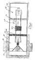
- FIG. 1 is shown a schematic diagram of the MRI and external beam RT therapy system within the external beam bunker room configuration.
- This diagram includes a magnet 10, having a bore 10A into which a patient 12 can be received on a patient couch top 15, which is attached to a patient couch 13.
- the movable magnet is carried on a rail system 25 with a support 23 suspended on the rail system. Further details of this construction are available from published US application 2008/0038712 .
- a suitable radiation therapy system 4 is available from Varian. This can use different radiation including proton beams, brachytherapy or X-ray.
- the Varian radiation therapy system is capable of delivering therapeutic radiation to the patient using an x-ray beam formed through a multi-leaf collimator to modulate the intensity of the radiation delivered.
- the Varian radiation therapy unit also includes a gantry-mounted x-ray imaging system 4A capable of performing cone-beam CT imaging immediately prior to radiation therapy, which enables image-guided radiotherapy.
- the Varian radiation therapy system is a device capable of delivering brachytherapy.
- This system also includes an image-guidance system that consisted of an x-ray imaging system. The disclosure of this material is incorporated herein by reference.
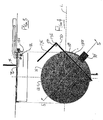
- the Patient Handling System or support table is shown in Figure 3 , indicated generally at 13 and 15.
- the patient support table 13 includes a base or pedestal 13A which allows the base to move a patient support portion 15 to required locations in height and in orientation.
- the patient support portion 15 At the top of the base 13A is mounted the patient support portion 15 in the form of a generally planar body 15 formed of a fiber reinforced plastics material so as to define a surface area sufficient for supporting the patient while lying on the patient support portion.
- the patient and the support structure are rotated 180 degrees from the position of the RT isocentre 16, with the movable MRI in position for imaging.
- the pedestal 13A is mounted on a turntable 18 for rotation about a vertical axis.
- the table can be a multi axis movable or "robot" table of a type also available from Varian. This acts to hold the base stationary while the table top can be moved to any orientation around the base and relative to axes transverse to the base.
- the table is shown including the base 18, toe portion 18X, heel portion 18Y, support wheels 18Z, motors 33 and couch or table top 15.
- safety control systems 18T at a suitable location relative to the system and integrated into the operation of the patient support table to prevent movement when in position for MR imaging to mitigate the possibility of collision between the patient support table and the RF-shielded door arrangement.
- the patient support table 13 is arranged to rotate 180 degrees from the isocentre of the treatment apparatus for cooperation with the MR magnet in MR imaging procedures, and then rotate back to the isocentre for treatment.
- the patient support table 13 employs several electronic motors 33 designed to provide different degrees of motion with the motors and controls therefor arranged to avoid interaction of the MRI static magnetic field.
- the longitudinal range of motion of the patient support table is extended to provide a safe distance between the static magnetic field of the magnet and positional motors in the patient support table.
- the automated system de-energizes the motors 33 once the patient support table is locked in place for MR imaging, and prevents any unsafe actions once locked into place.
- the safety system also guarantees that the patient support table is in the appropriate locked position prior to the magnet moving over the patient.
- the materials in the table top 15 of the patient support table are both MR compatible and radiolucent to enable both MR and X-ray imaging procedures.
- the table top 15 incorporates placeholders for RF coils 24 required for imaging the head and neck or the thorax, abdomen and/or lower pelvic region.
- the table top 15 also includes notches at the end of the table top required to maintain a similar function to standard linear accelerator and CT patient table tops.
- the table top 15 uses radiolucent and MRI compatible materials in the table top which allows the patient support table to be used in MRI and X-ray imaging systems without degrading the image quality of either system.
- the system further includes a receive coil system generally indicated at 24, which receives MR signals generated from the human body in a conventional manner.
- An RF control system acts to control the transmit body coil 11 and to receive the signals from the receive coil in the general area of 12.
- the receive coils are attached to the outside of the magnet for transport back to the diagnostic room.
- the external beam bunker room 26 is enclosed within walls 20, ceiling 14 and floor 26A comprised of radiation and RF shield material.
- the external beam RT room 26 is separated from a diagnostic imaging room 27 by a set of radiation and RF shielded bunker doors 19, so as to prevent radiation exposure to subjects in the adjacent diagnostic room during RT treatment delivery.
- the external beam bunker doors 19 are open during the imaging procedure and closed during RT delivery.
- a second set of RF shield doors 17, situated between the RT and MRI system, are used to isolate the RF generating components of the RT from the MRI system. These doors account for the RF shielding requirements across the turntable portion 18 of the patient support table 13. These doors are closed for MRI procedures and opened for RT delivery.
- An egress switch 17A is included within the RF-shielded doors to enable a manual override, which allows someone trapped behind the RF doors to open the RF doors even in the event of a power outage.
- the RF shield doors 17 are opened, and the MRI system is moved out of the external beam RT room 26.
- the RF-shielded doors 19 between the MRI and RT systems 17 are opened, and the patient 12 is rotated 180 degrees to the RT position using the patient support table 13.
- the patient alignment is adjusted based on the imaging results, and the RT beam is delivered from the treatment apparatus 4 to the lesion via the conventional collimator and rotating support.
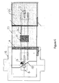
- Figures 1 and 2 the three-room configuration is displayed, with the rooms for external beam treatment 26, diagnostic imaging 27 and brachytherapy 30.
- RF and radiation-shielded doors 31 are placed between the diagnostic room 27 and brachytherapy bunker 30.
- the patient is positioned on the brachytherapy support table 32, which can allow the MRI system to move over the patient, and also has the necessary patient supports for brachytherapy procedures.
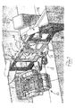
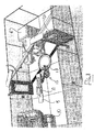
- Figure 3 provides a sketch of the complete room configuration for the three-room configuration with brachytherapy.
- components such as the two patient cameras 34, MR-compatible pot lights 35, IR tracking camera system 36 are positioned within the system room configuration.
- the third patient camera 37 is a radiation hardened camera that has electrical components not seriously affected by radiation exposure.
- the egress switch 17A is also included in Figure 3 .
- LCD monitors 36A are positioned at approximately position 38 to be easily visible by the clinical staff in the room.
- the bunker room also includes cabinets 39 for storage of immobilization and other radiotherapy devices.
- the MR coils used in the imaging procedures are located in the diagnostic room storage cabinets 40.
- an MR-compatible camera 41 is mounted inside the bore 10A of the movable MRI system 10. Speakers and a microphone are installed at approximately position 42, which enable continuous communication with the patient when the clinical staff are outside of the room.
- a personnel access sliding door 43 is designed into the room to provide direct access to the bunker room.
- the room also has a laser system 44 mounted on the bunker room wall 20, that allows the clinical staff to accurately position the patient prior to MR imaging or radiation therapy delivery.
- the apparatus for radiation therapy of a patient therefore includes the patient support table 13, a magnetic resonance imaging system for acquiring MR images of an imaging volume including the target location of the patient and the radiation treatment apparatus 4.
- the MR imaging system includes the MR magnet 10 with gradient coil 10A operable to generate a variable magnetic field to be applied to the patient, the magnet having a cylindrical bore 10A for surrounding the target location of the patient.
- the imaging system further includes the RF transmit coil arrangement 11 for generating an RF pulse in a transmit stage to be applied to the subject to be imaged such that the subject generates an MR signal in response to the magnetic field and the RF pulse applied.
- the signal is picked up by the receive coil arrangement 24 for acquiring the MR signal in a receive stage.
- the received signal is transmitted to a signal processing system 24A for receiving the MR signal for carrying out signal processing by which an image is generated.
- the beam or brachytherapy treatment apparatus 4 is arranged for applying a radiation therapy to a target location in the patient on the support table.
- the patient support table 15 and the treatment apparatus 4 are mounted in a treatment room having an opening 19A which includes a radiation shielded door arrangement 19 defined by two doors movable at right angles to the walls to a center closed position operable to close the opening 19A.
- the MR magnet 10 is mounted for movement from a position exterior of the radiation shielded door arrangement 19 into or through the opening 19A to an imaging position for cooperation with the patient on the patient support table 15 for MR imaging.
- the RT system 4 is separated from the magnet during imaging by the RF-shielded door arrangement 17 in the treatment room arranged to be movable between a closed position, separating at least part of the treatment apparatus from the magnet when in the imaging position, and an open position in which the treatment apparatus is accessible to the patient on the patient support table for radiation therapy.
- the RF-shielded door arrangement 17 is arranged in the closed position to isolate RF noise critical electronic components of the treatment apparatus 4 from the magnet 10 and receive coil arrangement 24 while allowing the critical electronic components of the treatment apparatus 4 to remain active without shutdown. This is necessary to avoid unacceptable delays which would be caused by a shut down of the system and restarting.
- the RF-shielded door arrangement 17 includes a suitable conductive layer typically formed of copper which halts and RF signals at the conductor. As shown in Figures 3 and 4 , the RF-shielded door arrangement includes doors or components 17 which together span the treatment room and which extend at an inclined angle to the patient support table. Thus there is provided an RF shielded wall portion 17B arranged on each side of the treatment apparatus at an angle to a longitudinal axis of the patient support table which can remain fixed and in position partly spanning the room. Each wall portion 17B cooperates with a respective RF shielded door 17 which can move across the treatment room along its respective wall portion from the inner edge of the respective wall portion so that the doors meet at the middle and form a continuous RF conductive shield.
- the position of the wall portions 17B is such that the table can rotate around the vertical central axis to take up its two positions while moving inside the inner edges 17C of the wall portions.
- the doors 17D and 17E meet at a point 17F which is symmetrical to the center line L of the system, and both doors extend across the turntable 18.
- the RF-shielded door 17D extends across a part 18 of the base so as to exclude the main part 18C of the base from the area containing the MR magnet.
- a portion of the base 18 as indicated at 18G is arranged inside the area of the magnet with the toe portion of the couch.
- the RF-shielding door arrangement 17 includes a RF-shielding inflatable bladder 7J in a bottom edge 7K of the doors that maintains RF-shielding across the base 18 of the patient support table.
- the surface baseplate of the turntable 18 is formed of a conductive material and there is provided a movable contactor 18H in the form of an inflatable bladder connected to the RF shield for engaging the turntable.
- the continuous conductive shield communicates through the turntable 18C and the door 17D, mounting the parts of the table which are inside the zone of the magnet so that they are all shielded from the RF signals generated by the quiescent but active treatment system in the zone behind the doors 17.
- the two parts 17D, 17E of the doors come together at an apex and are inclined to a longitudinal axis of the room so as to enclose the treatment system 4 on the left of the doors within the triangular shape defined by the two doors.
- Cables for providing control signals to the patient support table pass through a gland at the part of the RF shield defined by the portion 18G of the turntable.
- an RF filter system 18L is connected in the cables to filter the signals.
- detectors 17X on the RF-shielded door arrangement to prevent the door arrangement from closing to the position 17F if there is an object within the path of movement.
- three rooms including a first room for the Radiation treatment system 26, a third room 30 for the brachytherapy system combined with a second intermediate diagnostic room 27 in the middle to provide a three-room solution that provides image-guidance for both external beam and brachytherapy RT procedures using the same movable MRI magnet.
- Figures 1 and 2 there are provided two separate rooms where the first is a radiation-shielded "bunker" that houses the treatment apparatus and the second room houses the MR magnet for basic diagnostic procedures.
- the RF shielding door arrangement indicated generally at 171 is different in that it includes a part 172 extending fully across the turntable 18 to a position 173, 174 on either side of the turntable 18.
- the treatment apparatus 4 includes a head 4B rotatable about an axis longitudinal of the treatment room.
- the head 4B rotates around the longitudinal axis to direct the radiation to the treatment location from different angles around the patient.
- the room configuration includes a row 26A of rooms 26B to 26E each having a respective treatment apparatus, a respective patient support table and a respective radiation shielded door arrangement and the magnet is arranged to move along a path or passageway 26F outside the row of radiation shielded door arrangements. From this path, the magnet is arranged to move linearly along the path 26G outside the row of radiation shielded door arrangements to each room in turn as required. From this position the magnet rotates about a vertical axis 26H at each room to cooperate with the patient support table therein. In addition to the rotation, the magnet may also move in a direction 26L at right angles to the path 26G to enter the opening of the room concerned. However in some arrangements the magnet may not be able to move in the direction 26L and the cooperation between the table and the magnet is achieved by movement of the table alone.
- Figures 10A to 10E are shown a number of different embodiments of couch top designed to mount on the Varian robotic table mentioned above.
- the table top is manufactured of materials which make it MR compatible and radiolucent so as to allow imaging by the MR system and by the x-ray imaging system 4A of the treatment system 4 without generation of imaging artifacts.
- FIG 10A there is shown a one piece top 15 having a length to receive the whole body of the patient including an end section 151 which underlies the head.
- a first slot in the thickness of the top is provided at 24X to allow a posterior coil to be inserted at the pelvic region for pelvic imaging.
- a second slot in the thickness of the top is provided at 24Y to allow a posterior coil to be inserted at the head region 151 for head imaging.
- FIGs 10B and 10C are shown three piece tops with a base piece 152, a connector piece 153 and a head support piece 154, 155.
- the connector piece provides connector structures to hold the head piece in place at the end of the base piece.
- Various designs of connector can be provided.
- a slot 24 X is provided in the base piece in each arrangement.
- the head support 155 in Figure 10C is merely a flat support plate.
- the head support 154 is provided as a head/neck treatment mode shaped to provide minimum material to reduce the interference with the radiation.
- FIGS 10D and 10E are shown two piece tops with a base piece 152 and a head support piece 154, 155, where the connector piece 153 is omitted and the connector function defined instead between the base and head sections directly.
- Various designs of connector can be provided.
- a slot 24 X is provided in the base piece in each arrangement.
- the head supports 154 and 155 are as previously described.
Landscapes
- Health & Medical Sciences (AREA)
- Life Sciences & Earth Sciences (AREA)
- Nuclear Medicine, Radiotherapy & Molecular Imaging (AREA)
- Engineering & Computer Science (AREA)
- Physics & Mathematics (AREA)
- Biomedical Technology (AREA)
- General Health & Medical Sciences (AREA)
- Radiology & Medical Imaging (AREA)
- Veterinary Medicine (AREA)
- Pathology (AREA)
- Public Health (AREA)
- Animal Behavior & Ethology (AREA)
- Surgery (AREA)
- Molecular Biology (AREA)
- Medical Informatics (AREA)
- Heart & Thoracic Surgery (AREA)
- Biophysics (AREA)
- High Energy & Nuclear Physics (AREA)
- Pulmonology (AREA)
- Theoretical Computer Science (AREA)
- Condensed Matter Physics & Semiconductors (AREA)
- General Physics & Mathematics (AREA)
- Radiation-Therapy Devices (AREA)
- Magnetic Resonance Imaging Apparatus (AREA)
Claims (15)
- Vorrichtung zur Strahlentherapie bei einem Patienten, umfassend:einen Strahlenbehandlungsraum, der gegen Strahlung abgeschirmt ist und eine Öffnung besitzt, die eine gegen Strahlung abgeschirmte Türanordnung aufweist, mit der die Öffnung geschlossen werden kann,einen Patientenlagerungstisch,ein Magnetresonanztomografie-System zur Erfassung von MR-Aufnahmen eines Abbildungsvolumens, einschließlich der Zielstelle des Patienten,wobei das Tomografiesystem folgendes aufweist:einen MR-Magneten, mit dem ein bei dem Patienten anzuwendendes Magnetfeld erzeugt werden kann, wobei der Magnet eine zylindrische Bohrung zur Umgebung der Zielstelle des Patienten aufweist,eine RF-Sendespulenanordnung zur Erzeugung eines RF-Impulses in einer Sendestufe, der bei dem tomografisch zu untersuchenden Probanden angewandt wird, so dass der Proband als Antwort auf das angewandte Magnetfeld und den angewandten RF-Impuls ein MR-Signal erzeugt,eine Empfangsspulenanordnung zur Erfassung des MR-Signals in einer Empfangsspule,und ein Signalverarbeitungssystem zum Empfangen des MR-Signals zur Durchführung einer Signalverarbeitung, durch die ein Bild erzeugt wird,eine Behandlungsvorrichtung zur Anwendung einer Strahlentherapie auf eine Zielstelle in dem auf dem Patientenlagerungstisch befindlichen Patienten,wobei der Patientenlagerungstisch und die Behandlungsvorrichtung in dem Strahlenbehandlungsraum installiert sind,wobei der MR-Magnet so installiert ist, dass er von einer Stellung außerhalb der gegen Strahlung abgeschirmten Türanordnung in die Öffnung hinein zu einer Tomografiestellung bewegt werden kann, um im Zusammenwirken mit dem auf dem Patientenlagerungstisch befindlichen Patienten eine MR-Tomografie durchzuführen,wobei der MR-Magnet für eine Bewegung von einer Tomografiestellung zur äußeren Stellung zur Strahlenbehandlung des auf dem Patientenlagerungstisch befindlichen Patienten installiert ist,wobei eine Anordnung bereit gestellt wird, um zu verhindern, dass RF-Signale von der Behandlungsvorrichtung das MR-Tomografiesystem bei der Tomografie an dem Patientenlagerungstisch stören,und wobei sowohl der Patientenlagerungstisch als auch die Behandlungsvorrichtung so angeordnet sind, dass sie an einer Behandlungsstelle im Strahlenbehandlungsraum verbleiben, wenn der Magnet in die Tomografiestellung bewegt wird.
- Vorrichtung nach Anspruch 1, darüber hinaus umfassend eine gegen RF abgeschirmte Türanordnung im Strahlenbehandlungsraum, die so angeordnet ist, dass sie zwischen einer geschlossenen Stellung, die in der Tomografiestellung mindestens einen Teil der Behandlungsvorrichtung von dem Magneten abtrennt, und einer offenen Stellung, in der die Behandlungsvorrichtung Zugang zu dem auf dem Patientenlagerungstisch befindlichen Patienten hat, bewegt werden kann, wobei die gegen RF abgeschirmte Türanordnung in der geschlossenen Stellung angeordnet wird, um gegenüber RF-Rauschen empfindliche elektronische Bauteile der Behandlungsvorrichtung von dem Magneten und der Empfangsspulenanordnung zu isolieren, es dabei aber ermöglicht, dass die empfindlichen elektronischen Bauteile aktiv bleiben können ohne ausgeschaltet zu werden.
- Vorrichtung nach Anspruch 2, wobei der Patientenlagerungstisch eine Patientenlagerungsbank umfasst, die freischwingend an einem Lagerungsträger angebracht ist, der einen Drehtisch aufweist, der aus einem leitfähigen Material gebildet ist, zur Drehung um eine vertikale Achse und wobei die gegen RF abgeschirmte Türanordnung mindestens ein Teil aufweist, das sich über den Drehtisch hinweg erstreckt, um diesen Teil des Drehtisches von dem MR-Magneten abzusondern.
- Vorrichtung nach Anspruch 3, wobei der mindestens eine Teil der gegen RF abgeschirmten Türanordnung sich um einen Winkel geneigt zu einer Längsachse der Bohrung des Magneten über den Drehtisch erstreckt.
- Vorrichtung nach Anspruch 3 oder 4, wobei die gegen RF abgeschirmte Türanordnung einen Teil an jeder Seite der Behandlungsvorrichtung beinhaltet, der rechtwinklig zu der Längsachse angeordnet ist.
- Vorrichtung nach einem der Ansprüche 3 bis 5, wobei die gegen RF abgeschirmte Türanordnung ein erstes Teil aufweist, das sich teilweise über den Drehtisch erstreckt, und ein zweites Teil aufweist, das sich teilweise über den Drehtisch erstreckt, wobei die Teile an einem Scheitelpunkt aufeinander treffen, um die Behandlungsvorrichtung zu umschließen.
- Vorrichtung nach einem der Ansprüche 3 bis 5, wobei die gegen RF abgeschirmte Türanordnung ein erstes Teil beinhaltet, das sich vollständig über den Drehtisch bis zu einer Stellung auf einer der Seiten des Drehtischs erstreckt, an der die Behandlungsvorrichtung einen Kopf aufweist, der um eine Längsachse des Strahlenbehandlungsraums drehbar ist, und wobei der Kopf in eine Stellung an einer Seite des Patientenlagerungstischs gedreht ist, damit das Teil über den Drehtisch hinwegstreichen kann, während der Kopf sich auf einer Seite des von dem Magneten entfernten Teils befindet.
- Vorrichtung nach einem der vorherigen Ansprüche, wobei Kabel zur Bereitstellung von Steuersignalen zu dem Patientenlagerungstisch durch eine RF-Abschirmung geführt sind und einen RF-Filter aufweisen.
- Vorrichtung nach einem der vorherigen Ansprüche, wobei der Patientenlagerungstisch Steuerelemente aufweist, die durch Lichtwellenleiter gesteuert werden, die durch eine RF-Abschirmung hindurch geführt sind.
- Vorrichtung nach einem der Ansprüche 1 bis 9, die darüber hinaus mindestens drei in Reihe gelegene Räume umfasst, einschließlich dem Strahlenbehandlungsraum, der für eine Behandlung mit externem Strahl eingerichtet ist, einem dritten Raum für ein Brachytherapiesystem beabstandet von dem Strahlenbehandlungsraum und einem zweiten Diagnostikraum zwischen dem Strahlenbehandlungsraum und dem dritten Raum, wobei der Magnet in jeden dieser Räume bewegt werden kann, um eine Bildführung sowohl für die externen Strahl- als auch die Bradytherapie-RT-Verfahren unter Verwendung desselben beweglichen MRT-Magneten bereit zu stellen.
- Vorrichtung nach einem der Ansprüche 1 bis 9, die darüber hinaus mindestens drei in Reihe gelegene Räume umfasst, von denen mindestens einer den Strahlenbehandlungsraum umfasst, und wobei der Magnet so angeordnet ist, dass er sich linear, entlang einem Weg außerhalb der Reihe von Räumen bewegt und in jeden Raum hinein gedreht werden kann, um mit einem darin befindlichen Patientenlagerungstisch zusammen zu wirken.
- Vorrichtung nach einem der vorherigen Ansprüche, wobei der Patientenlagerungstisch so angeordnet ist, dass er sich um 180 Grad vom Isozentrum der Behandlungsvorrichtung dreht, um mit dem MR-Magneten in MR-Tomografieverfahren zusammen zu wirken, und sich dann zu Behandlungszwecken zum Isozentrum zurück dreht.
- Vorrichtung nach einem der vorherigen Ansprüche, wobei der Patientenlagerungstisch mehrere elektronische Motoren verwendet, die dafür ausgelegt sind, unterschiedliche Bewegungen bereit zu stellen, wobei die Motoren und die zugehörigen Steuerungen so angeordnet sind, dass ein Zusammenwirken mit dem statischen MRT-Magnetfeld verhindert wird.
- Vorrichtung nach einem der vorherigen Ansprüche, wobei ein automatisches Sicherheitssystem entsprechend eingerichtet ist, Motoren des Patientenlagerungstischs abzuschalten, wenn der Patientenlagerungstisch für die MR-Tomografie arretiert ist, und entsprechend eingerichtet ist, um unsichere Vorgänge nach erfolgtem Arretieren zu verhindern.
- Vorrichtung nach Anspruch 14, wobei das Sicherheitssystem entsprechend eingerichtet ist, um sicher zu stellen, dass der Patientenlagerungstisch sich in der richtigen Arretierungsstellung befindet, bevor der Magnet über den Patienten bewegt wird.
Applications Claiming Priority (1)
| Application Number | Priority Date | Filing Date | Title |
|---|---|---|---|
| US201161497236P | 2011-06-15 | 2011-06-15 |
Publications (2)
| Publication Number | Publication Date |
|---|---|
| EP2535086A1 EP2535086A1 (de) | 2012-12-19 |
| EP2535086B1 true EP2535086B1 (de) | 2014-08-20 |
Family
ID=46395467
Family Applications (1)
| Application Number | Title | Priority Date | Filing Date |
|---|---|---|---|
| EP20120172067 Active EP2535086B1 (de) | 2011-06-15 | 2012-06-14 | Integration von Magnetresonanzbildgebung in einer Strahlentherapiebehandlung |
Country Status (4)
| Country | Link |
|---|---|
| US (1) | US9138145B2 (de) |
| EP (1) | EP2535086B1 (de) |
| JP (1) | JP2013000596A (de) |
| ES (1) | ES2523825T3 (de) |
Families Citing this family (24)
| Publication number | Priority date | Publication date | Assignee | Title |
|---|---|---|---|---|
| US9168392B1 (en) * | 2008-05-22 | 2015-10-27 | Vladimir Balakin | Charged particle cancer therapy system X-ray apparatus and method of use thereof |
| US8825131B2 (en) | 2009-10-14 | 2014-09-02 | Nocimed, Llc | MR spectroscopy system and method for diagnosing painful and non-painful intervertebral discs |
| US8965094B2 (en) * | 2012-04-14 | 2015-02-24 | Nocimed, Llc | Magnetic resonance spectroscopy pulse sequence, acquisition, and processing system and method |
| WO2013165380A2 (en) * | 2012-04-30 | 2013-11-07 | Empire Technology Development, Llc | Infrared guide stars for endoscopic orienteering |
| WO2014015421A1 (en) * | 2012-07-27 | 2014-01-30 | University Health Network | Radiotherapy system integrating a radiation source with a magnetic resonance imaging apparatus with movable magnet components |
| EP2774537A1 (de) * | 2013-03-08 | 2014-09-10 | Imris Inc. | Patientenausrichtung in MRI-geführter Strahlungstherapie |
| US9399147B2 (en) | 2013-04-10 | 2016-07-26 | Mitsubishi Electric Corporation | Particle beam irradiation chamber |
| EP3004910B1 (de) * | 2013-06-06 | 2022-07-06 | Koninklijke Philips N.V. | Rf-geschirmter untersuchungsraum eines magnetresonanztomographiesystems |
| CN105792894B (zh) | 2013-09-30 | 2019-12-24 | 皇家飞利浦有限公司 | 用于外部射束放射治疗和短程治疗的医学仪器 |
| DE102014204381B4 (de) * | 2014-03-11 | 2017-03-23 | Siemens Healthcare Gmbh | Planung einer Brachytherapie-Behandlung aufgrund von Magnetresonanz-Bilddaten mit hyperintens dargestellten Bereichen |
| DE102014210458B4 (de) * | 2014-06-03 | 2016-01-14 | Siemens Aktiengesellschaft | Ermittlung einer Position einer zu bestrahlenden Zielregion eines Patienten in einer Bestrahlungseinrichtung |
| WO2016071733A1 (en) * | 2014-11-04 | 2016-05-12 | Synaptive Medical (Barbados) Inc. | Mri guided radiation therapy |
| DE102015212206A1 (de) * | 2015-06-30 | 2017-01-05 | Siemens Healthcare Gmbh | Verfahren zu einem Bestimmen zumindest eines patientenspezifischen Sicherheitsparameters sowie eine medizinische Bildgebungsvorrichtung hierzu |
| CN106267589B (zh) * | 2016-08-26 | 2019-05-21 | 东软医疗系统股份有限公司 | 一种直线加速器的控制方法及装置 |
| GB2561373A (en) * | 2017-04-11 | 2018-10-17 | Elekta ltd | Radiotherapy apparatus with calibration |
| CN111148471B (zh) | 2017-08-09 | 2023-08-22 | 反射医疗公司 | 用于发射引导放射治疗中的故障检测的系统和方法 |
| US11369806B2 (en) | 2017-11-14 | 2022-06-28 | Reflexion Medical, Inc. | Systems and methods for patient monitoring for radiotherapy |
| EP3547323A1 (de) | 2018-03-30 | 2019-10-02 | Koninklijke Philips N.V. | Brachytherapie-behandlungsplanungssystem |
| DE202018103733U1 (de) * | 2018-06-29 | 2018-08-16 | Medical Intelligence Medizintechnik Gmbh | Radiotherapiesystem |
| US20210316156A1 (en) * | 2018-12-26 | 2021-10-14 | Our United Corporation | Positioning method realized by computer, and radiotherapy system |
| US20200246095A1 (en) | 2019-01-31 | 2020-08-06 | Sino Canada Health Engineering Research Institute (Hefei) Ltd. | Moveable mri for imaging in surgical procedures |
| EP3756729A1 (de) * | 2019-06-24 | 2020-12-30 | Koninklijke Philips N.V. | Konfigurierbare strahlentherapieliegefläche zur simulation einer magnetresonanzstrahlentherapie |
| EP4010720A4 (de) * | 2019-08-05 | 2023-08-09 | The Board Of Regents Of The University Of Texas System | Inhomogenes mrt-system |
| KR20230061121A (ko) * | 2021-10-28 | 2023-05-08 | 경희대학교 산학협력단 | 저선량 전리방사선 치료장치 |
Family Cites Families (19)
| Publication number | Priority date | Publication date | Assignee | Title |
|---|---|---|---|---|
| US3720817A (en) | 1970-11-27 | 1973-03-13 | Jarian Ass | Automated radiation therapy machine |
| US5432544A (en) * | 1991-02-11 | 1995-07-11 | Susana Ziarati | Magnet room display of MRI and ultrasound images |
| US6419680B1 (en) | 1993-06-10 | 2002-07-16 | Sherwood Services Ag | CT and MRI visible index markers for stereotactic localization |
| US5402783A (en) | 1993-07-16 | 1995-04-04 | Eco-Safe International, Inc. | Method of minimizing distortion to radiation isodose contours and of targeting the depth of maximum dose at an effective tissue depth during radiation therapy |
| US5537452A (en) | 1994-05-10 | 1996-07-16 | Shepherd; Joseph S. | Radiation therapy and radiation surgery treatment system and methods of use of same |
| US5851182A (en) * | 1996-09-11 | 1998-12-22 | Sahadevan; Velayudhan | Megavoltage radiation therapy machine combined to diagnostic imaging devices for cost efficient conventional and 3D conformal radiation therapy with on-line Isodose port and diagnostic radiology |
| US5778047A (en) | 1996-10-24 | 1998-07-07 | Varian Associates, Inc. | Radiotherapy couch top |
| US6198957B1 (en) | 1997-12-19 | 2001-03-06 | Varian, Inc. | Radiotherapy machine including magnetic resonance imaging system |
| US6725078B2 (en) | 2000-01-31 | 2004-04-20 | St. Louis University | System combining proton beam irradiation and magnetic resonance imaging |
| GB2382512A (en) | 2001-07-20 | 2003-05-28 | Elekta Oncology Syst Ltd | MRI in guided radiotherapy and position verification |
| CA2556934C (en) | 2004-02-20 | 2018-05-22 | James F. Dempsey | System for delivering conformal radiation therapy while simultaneously imaging soft tissue |
| WO2007017847A1 (en) * | 2005-08-11 | 2007-02-15 | Navotek Medical Ltd. | Medical treatment system and method using radioactivity based position sensor |
| CN101278206B (zh) * | 2005-10-06 | 2012-09-05 | 皇家飞利浦电子股份有限公司 | 具有光纤连接的mr线圈 |
| JP2007144066A (ja) * | 2005-11-30 | 2007-06-14 | Hitachi Medical Corp | 医用診断・治療室 |
| KR100772893B1 (ko) | 2006-05-02 | 2007-11-05 | 삼성전자주식회사 | 향상된 잡음률과 검출 강도를 나타내는 올리고머 프로브어레이 및 그 제조 방법 |
| WO2009058733A1 (en) | 2007-10-28 | 2009-05-07 | Orbital Therapy Llc | A highly shielded radiation therapy system |
| US8190235B2 (en) * | 2008-06-04 | 2012-05-29 | Imris Inc. | System for magnetic resonance and X-Ray imaging |
| US8983573B2 (en) | 2008-06-24 | 2015-03-17 | Alberta Health Services | Radiation therapy system |
| US8245335B2 (en) | 2009-03-30 | 2012-08-21 | Imns Inc. | Support component for use in imaging by magnetic resonance and x-ray |
-
2012
- 2012-06-14 EP EP20120172067 patent/EP2535086B1/de active Active
- 2012-06-14 US US13/523,257 patent/US9138145B2/en active Active
- 2012-06-14 JP JP2012135225A patent/JP2013000596A/ja active Pending
- 2012-06-14 ES ES12172067.6T patent/ES2523825T3/es active Active
Also Published As
| Publication number | Publication date |
|---|---|
| EP2535086A1 (de) | 2012-12-19 |
| US20130317343A1 (en) | 2013-11-28 |
| JP2013000596A (ja) | 2013-01-07 |
| ES2523825T3 (es) | 2014-12-01 |
| US9138145B2 (en) | 2015-09-22 |
Similar Documents
| Publication | Publication Date | Title |
|---|---|---|
| EP2535086B1 (de) | Integration von Magnetresonanzbildgebung in einer Strahlentherapiebehandlung | |
| US11497937B2 (en) | System for delivering conformal radiation therapy while simultaneously imaging soft tissue | |
| US20130235969A1 (en) | Patient Alignment in MRI Guided Radiation Therapy | |
| AU2011348240B2 (en) | System and method for image guidance during medical procedures | |
| Ma et al. | Emerging technologies in stereotactic body radiotherapy | |
| US11141606B2 (en) | Magnetic resonance guided stereotactic radiosurgery | |
| US20130066134A1 (en) | Multiplexed Radiation Therapy | |
| EP2774537A1 (de) | Patientenausrichtung in MRI-geführter Strahlungstherapie | |
| AU2017208382A1 (en) | System for delivering conformal radiation therapy while simultaneously imaging soft tissue | |
| Hwang et al. | Image Guided Radiation Therapy | |
| Lu | Stereotactic body radiation therapy systems | |
| AU2013201172B2 (en) | System for Delivering Conformal Radiation Therapy While Simultaneously Imaging Soft Tissue | |
| Tachibana et al. | IGRT for IMRT | |
| Gillin | Special Procedures | |
| AU2015203460A1 (en) | System and method for image guidance during medical procedures |
Legal Events
| Date | Code | Title | Description |
|---|---|---|---|
| PUAI | Public reference made under article 153(3) epc to a published international application that has entered the european phase |
Free format text: ORIGINAL CODE: 0009012 |
|
| AK | Designated contracting states |
Kind code of ref document: A1 Designated state(s): AL AT BE BG CH CY CZ DE DK EE ES FI FR GB GR HR HU IE IS IT LI LT LU LV MC MK MT NL NO PL PT RO RS SE SI SK SM TR |
|
| AX | Request for extension of the european patent |
Extension state: BA ME |
|
| 17P | Request for examination filed |
Effective date: 20130619 |
|
| RBV | Designated contracting states (corrected) |
Designated state(s): AL AT BE BG CH CY CZ DE DK EE ES FI FR GB GR HR HU IE IS IT LI LT LU LV MC MK MT NL NO PL PT RO RS SE SI SK SM TR |
|
| GRAP | Despatch of communication of intention to grant a patent |
Free format text: ORIGINAL CODE: EPIDOSNIGR1 |
|
| INTG | Intention to grant announced |
Effective date: 20140110 |
|
| GRAS | Grant fee paid |
Free format text: ORIGINAL CODE: EPIDOSNIGR3 |
|
| GRAA | (expected) grant |
Free format text: ORIGINAL CODE: 0009210 |
|
| AK | Designated contracting states |
Kind code of ref document: B1 Designated state(s): AL AT BE BG CH CY CZ DE DK EE ES FI FR GB GR HR HU IE IS IT LI LT LU LV MC MK MT NL NO PL PT RO RS SE SI SK SM TR |
|
| REG | Reference to a national code |
Ref country code: GB Ref legal event code: FG4D |
|
| REG | Reference to a national code |
Ref country code: CH Ref legal event code: EP |
|
| REG | Reference to a national code |
Ref country code: AT Ref legal event code: REF Ref document number: 683105 Country of ref document: AT Kind code of ref document: T Effective date: 20140915 |
|
| REG | Reference to a national code |
Ref country code: IE Ref legal event code: FG4D |
|
| REG | Reference to a national code |
Ref country code: DE Ref legal event code: R096 Ref document number: 602012002793 Country of ref document: DE Effective date: 20141002 |
|
| REG | Reference to a national code |
Ref country code: ES Ref legal event code: FG2A Ref document number: 2523825 Country of ref document: ES Kind code of ref document: T3 Effective date: 20141201 |
|
| REG | Reference to a national code |
Ref country code: AT Ref legal event code: MK05 Ref document number: 683105 Country of ref document: AT Kind code of ref document: T Effective date: 20140820 |
|
| REG | Reference to a national code |
Ref country code: NL Ref legal event code: VDEP Effective date: 20140820 |
|
| REG | Reference to a national code |
Ref country code: LT Ref legal event code: MG4D |
|
| PG25 | Lapsed in a contracting state [announced via postgrant information from national office to epo] |
Ref country code: GR Free format text: LAPSE BECAUSE OF FAILURE TO SUBMIT A TRANSLATION OF THE DESCRIPTION OR TO PAY THE FEE WITHIN THE PRESCRIBED TIME-LIMIT Effective date: 20141121 Ref country code: FI Free format text: LAPSE BECAUSE OF FAILURE TO SUBMIT A TRANSLATION OF THE DESCRIPTION OR TO PAY THE FEE WITHIN THE PRESCRIBED TIME-LIMIT Effective date: 20140820 Ref country code: LT Free format text: LAPSE BECAUSE OF FAILURE TO SUBMIT A TRANSLATION OF THE DESCRIPTION OR TO PAY THE FEE WITHIN THE PRESCRIBED TIME-LIMIT Effective date: 20140820 Ref country code: NO Free format text: LAPSE BECAUSE OF FAILURE TO SUBMIT A TRANSLATION OF THE DESCRIPTION OR TO PAY THE FEE WITHIN THE PRESCRIBED TIME-LIMIT Effective date: 20141120 Ref country code: PT Free format text: LAPSE BECAUSE OF FAILURE TO SUBMIT A TRANSLATION OF THE DESCRIPTION OR TO PAY THE FEE WITHIN THE PRESCRIBED TIME-LIMIT Effective date: 20141222 Ref country code: BG Free format text: LAPSE BECAUSE OF FAILURE TO SUBMIT A TRANSLATION OF THE DESCRIPTION OR TO PAY THE FEE WITHIN THE PRESCRIBED TIME-LIMIT Effective date: 20141120 Ref country code: SE Free format text: LAPSE BECAUSE OF FAILURE TO SUBMIT A TRANSLATION OF THE DESCRIPTION OR TO PAY THE FEE WITHIN THE PRESCRIBED TIME-LIMIT Effective date: 20140820 |
|
| PG25 | Lapsed in a contracting state [announced via postgrant information from national office to epo] |
Ref country code: IS Free format text: LAPSE BECAUSE OF FAILURE TO SUBMIT A TRANSLATION OF THE DESCRIPTION OR TO PAY THE FEE WITHIN THE PRESCRIBED TIME-LIMIT Effective date: 20141220 Ref country code: LV Free format text: LAPSE BECAUSE OF FAILURE TO SUBMIT A TRANSLATION OF THE DESCRIPTION OR TO PAY THE FEE WITHIN THE PRESCRIBED TIME-LIMIT Effective date: 20140820 Ref country code: AT Free format text: LAPSE BECAUSE OF FAILURE TO SUBMIT A TRANSLATION OF THE DESCRIPTION OR TO PAY THE FEE WITHIN THE PRESCRIBED TIME-LIMIT Effective date: 20140820 Ref country code: HR Free format text: LAPSE BECAUSE OF FAILURE TO SUBMIT A TRANSLATION OF THE DESCRIPTION OR TO PAY THE FEE WITHIN THE PRESCRIBED TIME-LIMIT Effective date: 20140820 Ref country code: RS Free format text: LAPSE BECAUSE OF FAILURE TO SUBMIT A TRANSLATION OF THE DESCRIPTION OR TO PAY THE FEE WITHIN THE PRESCRIBED TIME-LIMIT Effective date: 20140820 |
|
| PG25 | Lapsed in a contracting state [announced via postgrant information from national office to epo] |
Ref country code: NL Free format text: LAPSE BECAUSE OF FAILURE TO SUBMIT A TRANSLATION OF THE DESCRIPTION OR TO PAY THE FEE WITHIN THE PRESCRIBED TIME-LIMIT Effective date: 20140820 |
|
| PG25 | Lapsed in a contracting state [announced via postgrant information from national office to epo] |
Ref country code: SK Free format text: LAPSE BECAUSE OF FAILURE TO SUBMIT A TRANSLATION OF THE DESCRIPTION OR TO PAY THE FEE WITHIN THE PRESCRIBED TIME-LIMIT Effective date: 20140820 Ref country code: DK Free format text: LAPSE BECAUSE OF FAILURE TO SUBMIT A TRANSLATION OF THE DESCRIPTION OR TO PAY THE FEE WITHIN THE PRESCRIBED TIME-LIMIT Effective date: 20140820 Ref country code: EE Free format text: LAPSE BECAUSE OF FAILURE TO SUBMIT A TRANSLATION OF THE DESCRIPTION OR TO PAY THE FEE WITHIN THE PRESCRIBED TIME-LIMIT Effective date: 20140820 Ref country code: RO Free format text: LAPSE BECAUSE OF FAILURE TO SUBMIT A TRANSLATION OF THE DESCRIPTION OR TO PAY THE FEE WITHIN THE PRESCRIBED TIME-LIMIT Effective date: 20140820 Ref country code: CZ Free format text: LAPSE BECAUSE OF FAILURE TO SUBMIT A TRANSLATION OF THE DESCRIPTION OR TO PAY THE FEE WITHIN THE PRESCRIBED TIME-LIMIT Effective date: 20140820 |
|
| REG | Reference to a national code |
Ref country code: DE Ref legal event code: R097 Ref document number: 602012002793 Country of ref document: DE |
|
| PG25 | Lapsed in a contracting state [announced via postgrant information from national office to epo] |
Ref country code: PL Free format text: LAPSE BECAUSE OF FAILURE TO SUBMIT A TRANSLATION OF THE DESCRIPTION OR TO PAY THE FEE WITHIN THE PRESCRIBED TIME-LIMIT Effective date: 20140820 |
|
| PLBE | No opposition filed within time limit |
Free format text: ORIGINAL CODE: 0009261 |
|
| STAA | Information on the status of an ep patent application or granted ep patent |
Free format text: STATUS: NO OPPOSITION FILED WITHIN TIME LIMIT |
|
| 26N | No opposition filed |
Effective date: 20150521 |
|
| PG25 | Lapsed in a contracting state [announced via postgrant information from national office to epo] |
Ref country code: SI Free format text: LAPSE BECAUSE OF FAILURE TO SUBMIT A TRANSLATION OF THE DESCRIPTION OR TO PAY THE FEE WITHIN THE PRESCRIBED TIME-LIMIT Effective date: 20140820 |
|
| PG25 | Lapsed in a contracting state [announced via postgrant information from national office to epo] |
Ref country code: MC Free format text: LAPSE BECAUSE OF FAILURE TO SUBMIT A TRANSLATION OF THE DESCRIPTION OR TO PAY THE FEE WITHIN THE PRESCRIBED TIME-LIMIT Effective date: 20140820 |
|
| REG | Reference to a national code |
Ref country code: CH Ref legal event code: PL |
|
| PG25 | Lapsed in a contracting state [announced via postgrant information from national office to epo] |
Ref country code: LU Free format text: LAPSE BECAUSE OF FAILURE TO SUBMIT A TRANSLATION OF THE DESCRIPTION OR TO PAY THE FEE WITHIN THE PRESCRIBED TIME-LIMIT Effective date: 20150614 |
|
| REG | Reference to a national code |
Ref country code: IE Ref legal event code: MM4A |
|
| PG25 | Lapsed in a contracting state [announced via postgrant information from national office to epo] |
Ref country code: CH Free format text: LAPSE BECAUSE OF NON-PAYMENT OF DUE FEES Effective date: 20150630 Ref country code: IE Free format text: LAPSE BECAUSE OF NON-PAYMENT OF DUE FEES Effective date: 20150614 Ref country code: LI Free format text: LAPSE BECAUSE OF NON-PAYMENT OF DUE FEES Effective date: 20150630 |
|
| PG25 | Lapsed in a contracting state [announced via postgrant information from national office to epo] |
Ref country code: BE Free format text: LAPSE BECAUSE OF FAILURE TO SUBMIT A TRANSLATION OF THE DESCRIPTION OR TO PAY THE FEE WITHIN THE PRESCRIBED TIME-LIMIT Effective date: 20140820 |
|
| REG | Reference to a national code |
Ref country code: FR Ref legal event code: PLFP Year of fee payment: 5 |
|
| PG25 | Lapsed in a contracting state [announced via postgrant information from national office to epo] |
Ref country code: MT Free format text: LAPSE BECAUSE OF FAILURE TO SUBMIT A TRANSLATION OF THE DESCRIPTION OR TO PAY THE FEE WITHIN THE PRESCRIBED TIME-LIMIT Effective date: 20140820 |
|
| PG25 | Lapsed in a contracting state [announced via postgrant information from national office to epo] |
Ref country code: HU Free format text: LAPSE BECAUSE OF FAILURE TO SUBMIT A TRANSLATION OF THE DESCRIPTION OR TO PAY THE FEE WITHIN THE PRESCRIBED TIME-LIMIT; INVALID AB INITIO Effective date: 20120614 Ref country code: SM Free format text: LAPSE BECAUSE OF FAILURE TO SUBMIT A TRANSLATION OF THE DESCRIPTION OR TO PAY THE FEE WITHIN THE PRESCRIBED TIME-LIMIT Effective date: 20140820 |
|
| REG | Reference to a national code |
Ref country code: FR Ref legal event code: PLFP Year of fee payment: 6 |
|
| PG25 | Lapsed in a contracting state [announced via postgrant information from national office to epo] |
Ref country code: CY Free format text: LAPSE BECAUSE OF FAILURE TO SUBMIT A TRANSLATION OF THE DESCRIPTION OR TO PAY THE FEE WITHIN THE PRESCRIBED TIME-LIMIT Effective date: 20140820 |
|
| PG25 | Lapsed in a contracting state [announced via postgrant information from national office to epo] |
Ref country code: TR Free format text: LAPSE BECAUSE OF FAILURE TO SUBMIT A TRANSLATION OF THE DESCRIPTION OR TO PAY THE FEE WITHIN THE PRESCRIBED TIME-LIMIT Effective date: 20140820 |
|
| REG | Reference to a national code |
Ref country code: FR Ref legal event code: PLFP Year of fee payment: 7 |
|
| PG25 | Lapsed in a contracting state [announced via postgrant information from national office to epo] |
Ref country code: MK Free format text: LAPSE BECAUSE OF FAILURE TO SUBMIT A TRANSLATION OF THE DESCRIPTION OR TO PAY THE FEE WITHIN THE PRESCRIBED TIME-LIMIT Effective date: 20140820 |
|
| PG25 | Lapsed in a contracting state [announced via postgrant information from national office to epo] |
Ref country code: AL Free format text: LAPSE BECAUSE OF FAILURE TO SUBMIT A TRANSLATION OF THE DESCRIPTION OR TO PAY THE FEE WITHIN THE PRESCRIBED TIME-LIMIT Effective date: 20140820 |
|
| PGFP | Annual fee paid to national office [announced via postgrant information from national office to epo] |
Ref country code: FR Payment date: 20230627 Year of fee payment: 12 Ref country code: DE Payment date: 20230620 Year of fee payment: 12 |
|
| PGFP | Annual fee paid to national office [announced via postgrant information from national office to epo] |
Ref country code: IT Payment date: 20230623 Year of fee payment: 12 Ref country code: GB Payment date: 20230622 Year of fee payment: 12 Ref country code: ES Payment date: 20230829 Year of fee payment: 12 |