EP2534449B1 - Verfahren zur positionsmessung - Google Patents
Verfahren zur positionsmessung Download PDFInfo
- Publication number
- EP2534449B1 EP2534449B1 EP11705441.1A EP11705441A EP2534449B1 EP 2534449 B1 EP2534449 B1 EP 2534449B1 EP 11705441 A EP11705441 A EP 11705441A EP 2534449 B1 EP2534449 B1 EP 2534449B1
- Authority
- EP
- European Patent Office
- Prior art keywords
- magnetic field
- magnet
- sensor
- coordinate
- determined
- Prior art date
- Legal status (The legal status is an assumption and is not a legal conclusion. Google has not performed a legal analysis and makes no representation as to the accuracy of the status listed.)
- Active
Links
Images


Classifications
-
- G—PHYSICS
- G01—MEASURING; TESTING
- G01D—MEASURING NOT SPECIALLY ADAPTED FOR A SPECIFIC VARIABLE; ARRANGEMENTS FOR MEASURING TWO OR MORE VARIABLES NOT COVERED IN A SINGLE OTHER SUBCLASS; TARIFF METERING APPARATUS; MEASURING OR TESTING NOT OTHERWISE PROVIDED FOR
- G01D5/00—Mechanical means for transferring the output of a sensing member; Means for converting the output of a sensing member to another variable where the form or nature of the sensing member does not constrain the means for converting; Transducers not specially adapted for a specific variable
- G01D5/12—Mechanical means for transferring the output of a sensing member; Means for converting the output of a sensing member to another variable where the form or nature of the sensing member does not constrain the means for converting; Transducers not specially adapted for a specific variable using electric or magnetic means
- G01D5/14—Mechanical means for transferring the output of a sensing member; Means for converting the output of a sensing member to another variable where the form or nature of the sensing member does not constrain the means for converting; Transducers not specially adapted for a specific variable using electric or magnetic means influencing the magnitude of a current or voltage
- G01D5/142—Mechanical means for transferring the output of a sensing member; Means for converting the output of a sensing member to another variable where the form or nature of the sensing member does not constrain the means for converting; Transducers not specially adapted for a specific variable using electric or magnetic means influencing the magnitude of a current or voltage using Hall-effect devices
- G01D5/145—Mechanical means for transferring the output of a sensing member; Means for converting the output of a sensing member to another variable where the form or nature of the sensing member does not constrain the means for converting; Transducers not specially adapted for a specific variable using electric or magnetic means influencing the magnitude of a current or voltage using Hall-effect devices influenced by the relative movement between the Hall device and magnetic fields
-
- G—PHYSICS
- G01—MEASURING; TESTING
- G01D—MEASURING NOT SPECIALLY ADAPTED FOR A SPECIFIC VARIABLE; ARRANGEMENTS FOR MEASURING TWO OR MORE VARIABLES NOT COVERED IN A SINGLE OTHER SUBCLASS; TARIFF METERING APPARATUS; MEASURING OR TESTING NOT OTHERWISE PROVIDED FOR
- G01D2205/00—Indexing scheme relating to details of means for transferring or converting the output of a sensing member
- G01D2205/95—Three-dimensional encoders, i.e. having codes extending in three directions
Definitions
- the invention relates to a method for position measurement according to the preamble of patent claim 1 and a related device according to the preamble of claim 9.
- Such a method can be used as an evaluation method for three-dimensional position determination in a magnetically operating position sensor.
- a device for position measurement with a magnet and with a magnetic field strength of the magnet detecting sensor wherein the magnet and / or the sensor cooperates with a movable element.
- the movable element By means of the movable element, a relative movement between the sensor and the magnet can be effected, such that the position of the movable element can be determined in a coordinate system according to the coordinates (x, y, z) on the basis of the magnetic field generated by the magnet and detected by the sensor.
- the sensor determines the components of the magnetic field strength (B x , B y , B z ) of the magnetic field acting in one or the same place in the sensor in three linearly independent spatial directions.
- the magnet is chosen so that it generates an analytically writable magnetic field.
- the invention has for its object to provide a method for position measurement for such a device, which operates in a simple manner.
- each coordinate x, y, z along a coordinate axis of the coordinate system in a half-space of the magnetic field and individually by the combination of the detected by the sensor components of the magnetic field strength (B x , B y , B z ) in all spatial directions of the coordinate system determined.
- the coordinates x, y, z are calculable for the spatial position.
- the method is further developed such that the coordinates x, y, z are described from a quotient relationship between the respective magnetic field strength corresponding to the coordinate axis (B x , B y , B z ), a location-dependent magnetic field quantity B 0 and a constant system size.
- the system size includes the magnetic permeability constant and the dipole moment of the magnet.
- the magnetic field size B 0 in turn comprises a component (B x , B y , B z ) in a spatial direction and the magnitude of the magnetic field strength. Since these are only simple calculation steps, a cost-effective microprocessor with low power is sufficient for their calculation.
- the method for determining the position can be further simplified by using a substantially ideal dipole field as the analytically writable magnetic field.
- a field of a cylinder magnet with a ratio of diameter to cylinder height of about 1: 1 is provided for this purpose, since such a cylinder magnet is simple and inexpensive to produce.
- the field of a spherical magnet can also be used as a dipole field.
- the magnetically operating device in which the magnetically operating device is used for position measurement, disturbances of the magnetic field due to the installation situation can be caused in the device.
- the magnet thus generates a magnetic field which is distorted at least at a surface not located between the sensor and the magnet.
- a surface for example, a metallic surface in the device, cause a shielding of the magnetic field.
- the method for position measurement can be configured as follows. In a first step, each coordinate x, y, z along a coordinate axis of the coordinate system in a half-space of an undistorted magnetic field is set to an initial value.
- a magnetic field model becomes of a surface with respect to the distortion surface symmetrical, in particular mirror-like, arrangement of at least two undistorted magnetic fields described.
- a position determination in the magnetic field model is determined by iterative combination of the components of the magnetic field strength (B x , B y , B z ) detected by the sensor in all spatial directions of the coordinate system and the magnetic field model.
- each coordinate x, y, z along a coordinate axis in a half-space of an undistorted magnetic field is determined to an initial value according to the above-described method for an undisturbed magnetic field.
- it may also be sufficient that the fixing of each coordinate x, y, z along a coordinate axis in a half-space of an undistorted magnetic field is freely selected to an initial value.
- the magnetic field model can be selected as a mirror-symmetrical magnetic field of two substantially ideal dipole fields, mirrored on the at least one surface causing the distortion and one-sided poled inverted. It is also appropriate for the magnetic field model to include a surface constant for taking account of boundary effects of the at least one surface causing the distortion. For example, the surface constant takes into account a frequently occurring, not ideal and thus incomplete shielding of the magnetic field by a metal surface.
- r (xyz) is the position vector for the magnet
- r s (x s y s z s ) the position vector for the mirror magnet and ⁇ the effectively effective permeability of the distortion causing surface and the underlying half space.
- a position-measuring device operating according to the method according to the invention can advantageously be used in a device with a metal housing.
- this may be a laundry treatment device.
- the device has a housing, which is in particular at least partially made of metal, and a rotatable drum suspended in the housing.
- the relative position of the drum in the housing is then determined by one of the methods described above.
- the position measurement in a washing machine can be used to detect the load of the laundry drum and / or to detect the vibration behavior of the laundry drum.
- larger drums with a capacity of 7 or 8 kg of laundry in a washing machine housing with a standard width of 60 cm can be realized. This is made possible by the position of the drum can be measured to the housing. Based on this signal, the washing machine control can detect impending stops of the drum to the housing and react accordingly.
- the advantages achieved by the invention are, in particular, that the position measurement due to the simple evaluation method with little effort and cost to implement. Therefore, the position measurement in cost-sensitive mass-produced items, such as household appliances, power tools o. The like., Can be used. Nevertheless, the position measurement works very accurate, more precise than before, as well as sensitive, so that it is also in safety-critical applications, such as in motor vehicles, usable. After all, it is also a faster evaluation method than before.
- a position measuring device 1 which comprises a magnet 2 and a sensor 3 detecting the magnetic field strength of the magnet 2.
- the magnet 2 and / or the sensor 3 interacts with a merely schematically drawn, movable element 4, so that by means of the movable element 4 thus a relative movement between the sensor 3 and the magnet 2 can be effected.
- the magnet 2 is arranged on the movable element 4, while the sensor 3 is arranged stationary.
- the sensor 3 on the movable member 4 and the magnet 2 may be arranged stationary, but this is not considered further.
- the magnet 2 is designed such that it generates an analytically writable magnetic field 5. As based on the in Fig.
- the dipole magnetic field 5 can also be generated by means of a spherical magnet, which is not shown further.
- the position of the movable element 4 corresponding to the coordinates x, y, z in a coordinate system can be determined on the basis of the magnetic field 5 detected by the sensor 3 and generated by the magnet 2.
- the position measuring device 1 operates according to the following method for position measurement.
- the components of the magnetic field strength of the magnetic field 5 acting in a single sensitive point 7 and consequently at the same location 7 are transformed into three linearly independent spatial directions 6, the so-called B-field components B x , B y , B z determined how in Fig. 1 is indicated schematically.
- Each coordinate x, y, z along a coordinate axis of the coordinate system is in a half-space of the magnetic field 5, wherein it is present in the Fig. 1
- the half space lying to the right of the magnet 2 is determined individually and unambiguously by the combination of the components of the magnetic field strength B x , B y , B z detected by the sensor 3 in all spatial directions 6 of the coordinate system.
- the magnetic field size B 0 comprises a component B x , B y , B z in a spatial direction 6 and the magnitude of the magnetic field strength B.
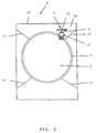
- FIG. 2 is the use of the position measuring device 1 in a household appliance, in a merely schematically outlined laundry treatment device, such as a washing machine 8 with a housing 10 shown.
- the washing machine 8 has a washing drum 9, which is rotatably mounted on a bearing assembly 4.
- the bearing assembly 4 is in turn attached via suspensions 11 in the washing machine 8, that vibrations, movements o. The like.
- the drum 9 are transmitted to the bearing assembly 4.
- the bearing assembly 4 thus represents the movable element, with which the magnet 2 cooperates.
- the magnet 2 is arranged in a holder 12 fastened to the movable element 4.
- the sensor 3 has a sensor housing 13, which is in the vicinity of the holder 12 and the magnet 2 assigned to a stationary element relative to the movable element 4 in the washing machine 9, namely fixed to the rear wall 14 of the housing 10.
- the coordinates x, y, z of the drum 9 determined by the position measuring device 1 are transmitted to a microcomputer in the washing machine 8, where vibrations, resonances or the like are compensated for by means of a corresponding control of the drive for the washing drum 9.
- the housing 10 of the washing machine 8 consists of a metal housing. However, metal causes a change of the magnetic field 5 in the manner of a shield. Since the Sensor 3 is located in the vicinity of the metallic housing rear wall 14, the magnetic field 5 generated by the magnet 2 is distorted at this at least one, not between the sensor 3 and the magnet 2 surface 14 by the field line of the magnet 2 deflected at the surface 14 so be that they extend largely in the surface 14, as shown schematically in FIG Fig. 3 you can see. In order to take account of this effect, the method for position measurement with the magnet 2 and with the sensor 3 detecting the magnetic field strength, that is to say the determination of the relative position of the drum 9 in the housing 10, is expanded as follows.
- each coordinate x, y, z along a coordinate axis 6 of the coordinate system in a half-space of an undistorted magnetic field 5 is set to an initial value x 0 , y 0 , z 0 .
- each coordinate x, y, z along a coordinate axis 6 in the half-space of an undistorted magnetic field 5 to an initial value x 0 , y 0 , z 0 according to the above formulas (1 *), (2 *) and (3 *
- a magnetic field model of a surface-symmetrical, in particular mirror-like, arrangement of at least two undistorted magnetic fields 5, 5 'with respect to the distortion-causing surface 14 is described, as in FIG Fig. 4 is shown.
- this magnetic field model contains a mirror-symmetrical magnetic field 5, 5 ', the magnetic field 5 being generated by the magnet 2 and the magnetic field 5' by a similar mirror magnet 2 'with respect to the surface 14.
- the magnetic fields 5, 5 'shown are thus two essentially ideal dipole fields, which are mirrored on the at least one surface 14 causing the distortion and are polinverted on one side.
- the magnetic field model may also comprise a surface constant ⁇ which serves to take account of boundary effects of the at least one surface 14 causing the distortion.
- the surface constant ⁇ takes into account, for example, that the real metal of the rear wall 14 of the housing is not an ideal "magnetic conductor". In other words, it is considered that in the real case the Housing rear wall 14 a certain proportion of the magnetic field lines also extends outside the housing rear wall 14, whereby ⁇ represents the effective effective permeability of the rear wall of the housing.
- the actual position determination takes place in this magnetic field model. This is determined starting from the initial value x 0 , y 0 , z 0 by iterative combination of the detected by the sensor 3 components of the magnetic field strength B x , B y , B z in all spatial directions 6 of the coordinate system and the magnetic field model.
- the initial value x 0 , y 0 , z 0 is first used in the magnetic field model and a first approximate value x 1 , y 1 , z 1 determined therefrom. This first approximation value is subsequently used again in the magnetic field model and from this a second approximation value x 2 , y 2 , z 2 is determined.
- x n-1, y n-1, z n-1 and x n, y n, z n are the same for the position in about, say for example to x n - 1 - x n ⁇ ⁇ y n - 1 - y n ⁇ ⁇ z n - 1 - z n ⁇ ⁇ applies, where ⁇ is a predetermined, the desired accuracy of the evaluation process determining barrier.
- r (xyz) is the position vector for the magnet 2
- ⁇ is the effective permeability of the distortion-causing surface 14 and the half space behind it.
- the value for ⁇ is approximately 0.7.
- the invention is not limited to the described and illustrated embodiments.
- the method for position measurement except in other household appliances in motor vehicles for example in motor vehicle locks, for chassis detection, for multimedia controls o. The like. Use find.
- this measuring method offers many other possible applications for general position detection in production and automation technology.
Landscapes
- Physics & Mathematics (AREA)
- General Physics & Mathematics (AREA)
- Measurement Of Length, Angles, Or The Like Using Electric Or Magnetic Means (AREA)
Description
- Die Erfindung betrifft ein Verfahren zur Positionsmessung nach dem Oberbegriff des Patentanspruchs 1 sowie eine diesbezügliche Vorrichtung nach dem Oberbegriff des Patentanspruchs 9.
- Ein derartiges Verfahren kann als Auswerteverfahren zur dreidimensionalen Positionsbestimmung in einem magnetisch arbeitenden Positionssensor zur Anwendung kommen.
- Aus der
DE 10 2008 024 103 A1 ist eine Vorrichtung zur Positionsmessung mit einem Magneten und mit einem die Magnetfeldstärke des Magneten detektierenden Sensor bekannt, wobei der Magnet und/oder der Sensor mit einem beweglichen Element zusammenwirkt. Mittels des beweglichen Elementes ist eine Relativbewegung zwischen dem Sensor und dem Magneten bewirkbar, derart dass die Position des beweglichen Elementes entsprechend den Koordinaten (x, y, z) in einem Koordinatensystem aufgrund des vom Sensor detektierten, vom Magneten erzeugten Magnetfelds feststellbar ist. Hierfür stellt der Sensor die im Sensor an einem beziehungsweise am selben Ort wirkenden Komponenten der Magnetfeldstärke (Bx, By, Bz) des Magnetfeldes in drei, linear unabhängigen Raumrichtungen fest. Der Magnet ist so gewählt, dass dieser ein analytisch beschreibbares Magnetfeld erzeugt. - Aus dem Stand der Technik sind weiterhin die Dokumente
DE 10 2005 009 381 A1 ,DE 10 2007 008 155 A1 ,US 2009/0217711 A1 undUS 2007/0167703 A1 bekannt. Diese Dokumente lehren jedoch keine analytischen Positionsbestimmungsverfahren, welche den Fachmann entsprechend der vorliegenden Erfindung anleiten. - Der Erfindung liegt die Aufgabe zugrunde, ein Verfahren zur Positionsmessung für eine solche Vorrichtung zu schaffen, das in einfacher Art und Weise arbeitet.
- Diese Aufgabe wird bei einem gattungsgemäßen Verfahren durch die kennzeichnenden Merkmale des Anspruchs 1 sowie bei einer diesbezüglichen Vorrichtung durch die kennzeichnenden Merkmale des Patentanspruchs 10 gelöst.
- Beim erfindungsgemäßen Verfahren wird jede Koordinate x, y, z entlang einer Koordinatenachse des Koordinatensystems in einem Halbraum des Magnetfelds einzeln und eindeutig durch die Kombination der von dem Sensor erfassten Komponenten der Magnetfeldstärke (Bx, By, Bz) in allen Raumrichtungen des Koordinatensystems ermittelt. Zur jeweiligen Positionsbestimmung genügt somit die Messung der Komponenten der Magnetfeldstärken Bx, By, Bz am dem einen Ort im Sensor, also lediglich die Messung eines Werte-Tripels, aus dem dann in einfacher Art und Weise die Koordinaten x, y, z für die räumliche Position berechenbar sind.
- Das Verfahren ist dahingehend weiterentwickelt, dass die Koordinaten x, y, z aus einer Quotientenbeziehung zwischen der jeweiligen der Koordinatenachse entsprechenden Magnetfeldstärke (Bx, By, Bz), einer von dem Ort abhängigen Magnetfeldgröße B0 und einer konstanten Systemgröße beschrieben werden. Dabei umfasst die Systemgröße die magnetische Permeabilitätskonstante und das Dipolmoment des Magneten. Die Magnetfeldgröße B0 umfasst wiederum eine Komponente (Bx, By, Bz) in einer Raumrichtung und den Betrag der Magnetfeldstärke. Da es sich hierbei lediglich um einfache Rechenschritte handelt, genügt für deren Berechnung ein kostengünstiger Mikroprozessor mit geringer Leistung.
- Insbesondere werden dabei die Koordinaten wie folgt ermittelt:


- Es ist somit festzustellen, dass das erfindungsgemäße Verfahren nur geringen apparativen Aufwand erfordert und sehr schnell arbeitet. Weitere Ausgestaltungen der Erfindung sind Gegenstand der Unteransprüche.
- Das Verfahren zur Positonsbestimmung lässt sich weiter vereinfachen, indem als analytisch beschreibbares Magnetfeld ein im Wesentlichen ideales Dipolfeld verwendet wird. Bevorzugterweise ist hierfür ein Feld eines Zylindermagneten mit einem Verhältnis von Durchmesser zu Zylinderhöhe von in etwa 1:1 vorgesehen, da ein solcher Zylindermagnet einfach und kostengünstig herstellbar ist. Als Dipolfeld lässt sich jedoch auch das Feld eines Kugelmagneten verwenden.
- In manchen Geräten, in denen die magnetisch arbeitende Vorrichtung zur Positionsmessung eingesetzt wird, können Störungen des Magnetfeldes aufgrund der Einbausituation im Gerät hervorgerufen werden. In derartigen Anwendungsfällen erzeugt der Magnet somit ein Magnetfeld, welches zumindest an einer, nicht zwischen dem Sensor und dem Magneten befindlichen Fläche verzerrt wird. Insbesondere kann eine solche Fläche, beispielsweise eine metallische Fläche im Gerät, eine Abschirmung des Magnetfeldes bewirken. Um auch in solchen Fällen eine korrekte Positionsbestimmung zu gewährleisten, lässt sich das Verfahren zur Positionsmessung wie folgt ausgestalten. In einem ersten Schritt wird jede Koordinate x, y, z entlang einer Koordinatenachse des Koordinatensystems in einem Halbraum eines unverzerrten Magnetfelds zu einem Anfangswert festgesetzt. In einem zweiten Schritt wird ein Magnetfeldmodell aus einer in Bezug zu der die Verzerrung bewirkenden Fläche flächensymmetrischen, insbesondere spiegelartigen, Anordnung von mindestens zwei unverzerrten Magnetfeldern beschrieben. In einem dritten Schritt wird schließlich eine Positionsbestimmung im Magnetfeldmodell, ausgehend vom Anfangswert durch iterative Kombination der von dem Sensor erfassten Komponenten der Magnetfeldstärke (Bx, By, Bz) in allen Raumrichtungen des Koordinatensystems und des Magnetfeldmodells ermittelt. Auch hier ist festzustellen, dass dieses Verfahren in einfacher und schneller Art und Weise die Positionsbestimmung ermöglicht.
- Zweckmäßigerweise wird die Festsetzung jeder Koordinate x, y, z entlang einer Koordinatenachse in einem Halbraum eines unverzerrten Magnetfelds zu einem Anfangswert nach dem oben beschriebenen Verfahren für ein ungestörtes Magnetfeld ermittelt. Es kann im einfachen Falle jedoch auch genügen, dass die Festsetzung jeder Koordinate x, y, z entlang einer Koordinatenachse in einem Halbraum eines unverzerrten Magnetfelds zu einem Anfangswert frei gewählt wird.
- In weiterer Ausgestaltung, die sich durch eine einfache Auswertung im Hinblick auf die Positionsbestimmung auszeichnet, kann das Magnetfeldmodell als ein spiegelsymmetrisches Magnetfeld zweier im wesentlichen idealer Dipolfelder, gespiegelt an der mindestens einen die Verzerrung bewirkenden Fläche und einseitig polinvertiert gewählt werden. Es bietet sich weiterhin an, dass das Magnetfeldmodell eine Flächenkonstante zur Berücksichtigung von Grenzflächeneffekten der mindestens einen die Verzerrung bewirkenden Fläche umfasst. Beispielsweise berücksichtigt die Flächenkonstante eine in der Realität häufig vorliegende, nicht ideale und somit unvollständige Abschirmung des Magnetfeldes durch eine Metallfläche.
- Insbesondere kann Magnetfeldmodell wie folgt bestimmt sein:

- Eine nach dem erfindungsgemäßen Verfahren arbeitende Positionsmesseinrichtung lässt sich vorteilhafterweise in einer Vorrichtung mit einem Metallgehäuse einsetzen. Beispielsweiese kann es sich dabei um ein Wäschebehandlungsgerät handeln. Das Gerät besitzt ein Gehäuse, das insbesondere wenigstens teilweise aus Metall besteht, und eine im Gehäuse aufgehängte drehbare Trommel. Die relative Position der Trommel im Gehäuse wird dann durch eines der oben beschriebenen Verfahren ermittelt. Beispielsweise kann in einer Waschmaschine die Positionsmessung zur Beladungserkennung der Wäschetrommel und/oder zur Detektierung des Schwingungsverhaltens der Wäschetrommel dienen. Vorteilhafterweise sind dann größere Trommeln mit einem Fassungsvermögen von 7 oder 8 kg Wäsche in einem Waschmaschinengehäuse mit einer Standardbreite von 60 cm realisierbar. Dies wird dadurch ermöglicht, indem die Position der Trommel zum Gehäuse gemessen werden kann. Basierend auf diesem Signal kann die Waschmaschinensteuerung drohende Anschläge der Trommel an das Gehäuse erkennen und entsprechend reagieren.
- Die mit der Erfindung erzielten Vorteile bestehen insbesondere darin, daß die Positionsmessung aufgrund des einfachen Auswerteverfahrens mit geringem Aufwand und kostengünstig zu realisieren ist. Daher ist die Positionsmessung in kostensensitiven Massenartikeln, wie Haushaltsgeräten, Elektrowerkzeugen o. dgl., einsetzbar. Dennoch arbeitet die Positionsmessung sehr genau, und zwar präziser als bisher, sowie auch empfindlich, so dass diese auch in sicherheitskritischen Anwendungen, beispielsweise in Kraftfahrzeugen, verwendbar ist. Schließlich handelt es sich auch um ein schnelleres Auswerteverfahren als bisher.
- Ausführungsbeispiele der Erfindung mit verschiedenen Weiterbildungen und Ausgestaltungen sind in den Zeichnungen dargestellt und werden im folgenden näher beschrieben. Es zeigen
- Fig. 1
- schematisch eine einen Magneten sowie einen Sensor aufweisende Positionsmessvorrichtung in der Art einer Prinzipskizze,
- Fig. 2
- schematisch eine Waschmaschine mit einer einen Magneten sowie einen Sensor aufweisenden Positionsmessvorrichtung,
- Fig. 3
- ein von einer metallischen Fläche verzerrtes Magnetfeld und
- Fig. 4
- ein die Verzerrung an einer metallischen Fläche berücksichtigendes Magnetfeldmodell.
- In der als Prinzipskizze dienenden
Fig. 1 ist eine Positionsmessvorrichtung 1 gezeigt, die einen Magneten 2 und einen die Magnetfeldstärke des Magneten 2 detektierenden Sensor 3 umfasst. Der Magnet 2 und/oder der Sensor 3 wirkt mit einem lediglich schematisch gezeichneten, beweglichen Element 4 zusammen, so dass mittels des beweglichen Elementes 4 somit eine Relativbewegung zwischen dem Sensor 3 und dem Magnet 2 bewirkt werden kann. Vorliegend ist der Magnet 2 an dem beweglichen Element 4 angeordnet, während der Sensor 3 ortsfest angeordnet ist. Selbstverständlich kann auch umgekehrt der Sensor 3 am beweglichen Element 4 sowie der Magnet 2 ortsfest angeordnet sein, was jedoch nicht weiter betrachtet ist. Der Magnet 2 ist so ausgestaltet, dass dieser ein analytisch beschreibbares Magnetfeld 5 erzeugt. Wie anhand der inFig. 1 eingezeichneten Feldlinien des Magnetfeldes 5 zu erkennen ist handelt es sich dabei um ein im Wesentlichen ideales Dipolfeld, wobei das Dipol-Magnetfeld 5 von einem Zylindermagneten 2 mit einem Verhältnis von Durchmesser zu Zylinderhöhe von in etwa 1:1 erzeugt wird. Das Dipol-Magnetfeld 5 lässt sich auch mittels eines Kugelmagneten erzeugen, was jedoch nicht weiter gezeigt ist. - Die Position des beweglichen Elementes 4 entsprechend den Koordinaten x, y, z in einem Koordinatensystem, bei dem es sich vorliegend um ein kartesisches Koordinatensystem handelt, ist aufgrund des vom Sensor 3 detektierten, vom Magneten 2 erzeugten Magnetfeldes 5 feststellbar. Hierzu arbeitet die Positionsmessvorrichtung 1 nach folgendem Verfahren zur Positionsmessung.
- Zunächst werden im Sensor 3 die in einem einzigen sensitiven Punkt 7 und folglich an dem einen, selben Ort 7 wirkenden Komponenten der Magnetfeldstärke des Magnetfeldes 5 in drei linear unabhängige Raumrichtungen 6, die sogenannten B-Feld-Komponenten Bx, By, Bz festgestellt, wie in
Fig. 1 schematisch angedeutet ist. Jede Koordinate x, y, z entlang einer Koordinatenachse des Koordinatensystems wird in einem Halbraum des Magnetfelds 5, wobei es sich vorliegend in derFig. 1 um den rechts vom Magneten 2 liegenden Halbraum handelt, einzeln und eindeutig durch die Kombination der von dem Sensor 3 erfassten Komponenten der Magnetfeldstärke Bx, By, Bz in allen Raumrichtungen 6 des Koordinatensystems ermittelt. Zur Bestimmung der Koordinaten x, y, z dient eine Quotientenbeziehung zwischen der jeweiligen der Koordinatenachse entsprechenden Magnetfeldstärke Bx, By, Bz, einer von dem Ort abhängigen Magnetfeldgröße B0 und einer konstanten Systemgröße. Die Systemgröße umfasst die magnetische Permeabilitätskonstante bzw. die magnetische Feldkonstante µ0 und das Dipolmoment pz des Magneten 2. Die Magnetfeldgröße B0 umfasst eine Komponente Bx, By, Bz in einer Raumrichtung 6 und den Betrag der Magnetfeldstärke B. Insbesondere können die Koordinaten x, y, z mit Hilfe der Quotientenbeziehung wie folgt ermittelt werden:


- In
Fig. 2 ist die Verwendung der Positionsmessvorrichtung 1 in einem Haushaltsgerät, und zwar in einem lediglich schematisch skizzierten Wäschebehandlungsgerät, beispielsweise einer Waschmaschine 8 mit einem Gehäuse 10, gezeigt. Die Waschmaschine 8 besitzt eine Waschtrommel 9, die drehbar an einer Lageranordnung 4 gelagert ist. Die Lageranordnung 4 ist ihrerseits über Aufhängungen 11 so in der Waschmaschine 8 befestigt, dass Schwingungen, Bewegungen o. dgl. der Trommel 9 auf die Lageranordnung 4 übertragen werden. Die Lageranordnung 4 stellt somit das bewegliche Element dar, mit der der Magnet 2 zusammenwirkt. Hierfür ist der Magnet 2 in einer am beweglichen Element 4 befestigten Halterung 12 angeordnet. Der Sensor 3 besitzt ein Sensorgehäuse 13, das in der Nähe der Halterung 12 und dem Magneten 2 zugeordnet an einem gegenüber dem beweglichen Element 4 feststehenden Element in der Waschmaschine 9, und zwar an der Gehäuserückwand 14 des Gehäuses 10 fixiert ist. Die von der Positionsmessvorrichtung 1 ermittelten Koordinaten x, y, z der Trommel 9 werden zu einem Mikrocomputer in der Waschmaschine 8 übertragen, wo anhand entsprechender Ansteuerung des Antriebs für die Waschtrommel 9 dann Schwingungen, Resonanzen o. dgl. ausgeglichen werden. - Das Gehäuse 10 der Waschmaschine 8 besteht aus einem Metallgehäuse. Metall bewirkt jedoch eine Veränderung des Magnetfeldes 5 in der Art einer Abschirmung. Da sich der Sensor 3 in der Nähe der metallischen Gehäuserückwand 14 befindet, wird das vom Magneten 2 erzeugte Magnetfeld 5 an dieser zumindest einen, nicht zwischen dem Sensor 3 und dem Magneten 2 befindlichen Fläche 14 verzerrt, indem die Feldlinie des Magneten 2 an der Fläche 14 derart abgelenkt werden, dass diese weitgehend in der Fläche 14 verlaufen, wie schematisch in
Fig. 3 zu sehen ist. Um diesen Effekt zu berücksichtigen, wird das Verfahren zur Positionsmessung mit dem Magneten 2 und mit dem die Magnetfeldstärke detektierenden Sensor 3, also die Ermittlung der relativen Position der Trommel 9 im Gehäuse 10, wie folgt erweitert. - In einem ersten Schritt wird jede Koordinate x, y, z entlang einer Koordinatenachse 6 des Koordinatensystems in einem Halbraum eines unverzerrten Magnetfelds 5 zu einem Anfangswert x0, y0, z0 festgesetzt. Bevorzugterweise erfolgt die Festsetzung jeder Koordinate x, y, z entlang einer Koordinatenachse 6 in dem Halbraum eines unverzerrten Magnetfelds 5 zu einem Anfangswert x0, y0, z0 nach den obigen Formeln (1*), (2*) und (3*) entsprechend dem Verfahren zur Positionsbestimmung für ein ungestörtes Magnetfeld 5. Andererseits ist es auch möglich, die Festsetzung jeder Koordinate x, y, z entlang einer Koordinatenachse 6 in dem Halbraum eines unverzerrten Magnetfelds 5 zu einem Anfangswert x0, y0, z0 in geeigneter Weise frei zu wählen.
- In einem zweiten Schritt wird ein Magnetfeldmodell aus einer in Bezug zu der die Verzerrung bewirkenden Fläche 14 flächensymmetrischen, insbesondere spiegelartigen, Anordnung von mindestens zwei unverzerrten Magnetfeldern 5, 5' beschrieben, wie in
Fig. 4 gezeigt ist. Zweckmäßigerweise enthält dieses Magnetfeldmodell ein spiegelsymmetrisches Magnetfeld 5, 5', wobei das Magnetfeld 5 vom Magneten 2 und das Magnetfeld 5' von einem gleichartigen Spiegelmagneten 2' bezüglich der Fläche 14 erzeugt wird. Bei den inFig. 4 gezeigten Magnetfeldern 5, 5' handelt es sich somit um zwei im wesentlichen ideale Dipolfelder, die an der mindestens einen die Verzerrung bewirkenden Fläche 14 gespiegelt und einseitig polinvertiert sind. Das Magnetfeldmodell kann noch eine Flächenkonstante η umfassen, die zur Berücksichtigung von Grenzflächeneffekten der mindestens einen die Verzerrung bewirkenden Fläche 14 dient. Die Flächekonstante η berücksichtigt beispielsweise, dass das reale Metall der Gehäuserückwand 14 kein idealer "magnetischer Leiter" ist. Mit anderen Worten wird berücksichtigt, dass im realen Fall der Gehäuserückwand 14 ein gewisser Anteil der magnetischen Feldlinien auch außerhalb der Gehäuserückwand 14 verläuft, womit η die effektiv wirksame Permeabilität der Gehäuserückwand darstellt. - In einem dritten Schritt erfolgt schließlich die eigentliche Positionsbestimmung in diesem Magnetfeldmodell. Diese wird ausgehend vom Anfangswert x0, y0, z0 durch iterative Kombination der von dem Sensor 3 erfassten Komponenten der Magnetfeldstärke Bx, By, Bz in allen Raumrichtungen 6 des Koordinatensystems und des Magnetfeldmodells ermittelt. Mit anderen Worten wird zunächst der Anfangswert x0, y0, z0 in das Magnetfeldmodell eingesetzt und daraus ein erster Näherungswert x1, y1, z1 ermittelt. Dieser erste Näherungswert wird anschließend wiederum in das Magnetfeldmodell eingesetzt und daraus ein zweiter Näherungswert x2, y2, z2 ermittelt. Die Iteration wird nun solange fortgesetzt bis zwei aufeinanderfolgende Näherungswerte xn-1, yn-1, zn-1 und xn, yn, zn für die Position in etwa gleich sind, also beispielsweise bis


- Insbesondere lässt sich das Magnetfeldmodell, bestehend aus der Anordnung von Magnet 2 und Spiegelmagnet 2' gemäß
Fig. 4 , wie folgt bestimmen:
- Dabei bedeuten r = (x y z) der Positionsvektor für den Magneten 2, rs = (xs ys zs) der Positionsvektor für den Spiegelmagneten 2' sowie η die effektiv wirksame Permeabilität der die Verzerrung bewirkenden Fläche 14 und des dahinter liegenden Halbraumes. Wie sich herausgestellt hat, beträgt bei den üblichen Materialien für die Gehäuserückwand 14 in einer Waschmaschine 8 der Wert für η in etwa 0,7.
- Die Erfindung ist nicht auf die beschriebenen und dargestellten Ausführungsbeispiele beschränkt. So kann das Verfahren zur Positionsmessung außer in sonstigen Haushaltsgeräten auch in Kraftfahrzeugen, beispielsweise in Kraftfahrzeugschlössern, zur Fahrwerkserkennung, für Multimedia-Bedienelemente o. dgl. Verwendung finden. Darüber hinaus bietet dieses Messverfahren viele weitere Einsatzmöglichkeiten für die allgemeine Positionserkennung in der Produktions- und Automatisierungstechnik.
-
- 1:
- Positionsmessvorrichtung
- 2:
- Magnet / Zylindermagnet
- 2':
- Spiegelmagnet
- 3:
- Sensor
- 4:
- bewegliches Element / Lageranordnung
- 5:
- Magnetfeld / Dipol-Magnetfeld / Dipolfeld
- 5':
- (spiegelsymmetrisches) Magnetfeld / Dipolfeld
- 6:
- Raumrichtung / Koordinatenachse
- 7:
- Ort (im Sensor) /sensitiver Punkt
- 8:
- Waschmaschine
- 9:
- Waschtrommel / Trommel
- 10:
- Gehäuse (von Waschmaschine)
- 11:
- Aufhängung
- 12:
- Halterung (für Magnet)
- 13:
- Sensorgehäuse
- 14:
- Gehäuserückwand / Fläche
Claims (9)
- Verfahren zur Positionsmessung mit einem Magneten (2) und mit einem die Magnetfeldstärke des Magneten (2) detektierenden Sensor (3), wobei der Magnet (2) und/oder der Sensor (3) mit einem beweglichen Element (4) zusammenwirkt, wobei mittels des beweglichen Elementes (4) eine Relativbewegung zwischen dem Sensor (3) und dem Magneten (2) bewirkbar ist, derart dass die Position des beweglichen Elementes (4) entsprechend den Koordinaten (x, y, z) in einem Koordinatensystem aufgrund des vom Sensor (3) detektierten, vom Magneten (2) erzeugten Magnetfelds (5) feststellbar ist, wobei der Magnet (2) ein analytisch beschreibbares Magnetfeld (5) erzeugt, und wobei der Sensor (3) die im Sensor (3) an einem Ort (7) wirkenden Komponenten der Magnetfeldstärke (Bx, By, Bz) des Magnetfeldes (5) in drei, linear unabhängigen Raumrichtungen (6) feststellt, wobei jede Koordinate x, y, z entlang einer Koordinatenachse (6) des Koordinatensystems in einem Halbraum des Magnetfelds (5) einzeln und eindeutig durch die Kombination der von dem Sensor (3) erfassten Komponenten der Magnetfeldstärke (Bx, By, Bz) in allen Raumrichtungen (6) des Koordinatensystems ermittelt wird dadurch gekennzeichnet, dass die Koordinaten (x, y, z) aus einer Quotientenbeziehung zwischen der jeweiligen der Koordinatenachse (6) entsprechenden Magnetfeldstärke (Bx, By, Bz), einer von dem Ort abhängigen Magnetfeldgröße B0 und einer konstanten Systemgröße, beschrieben werden, wobei die Systemgröße die magnetische Permeabilitätskonstante und das Dipolmoment des Magneten (2) umfasst sowie die Magnetfeldgröße B0 eine Komponente (Bx, By, Bz) in einer Raumrichtung (6) und den Betrag der Magnetfeldstärke umfasst, indem die Koordinaten wie folgt ermittelt werden:


- Verfahren zur Positionsmessung nach Anspruch 1, dadurch gekennzeichnet, dass als analytisch beschreibbares Magnetfeld (5) ein im Wesentlichen ideales Dipolfeld, vorzugsweise ein Feld eines Zylindermagneten (2) mit einem Verhältnis von Durchmesser zu Zylinderhöhe von in etwa 1:1, insbesondere ein Feld eines Kugelmagneten, vorgesehen ist.
- Verfahren zur Positionsmessung mit einem Magneten (2) und mit einem die Magnetfeldstärke detektierenden Sensor (3), wobei der Magnet (2) und/oder der Sensor (3) mit einem beweglichen Element (4) zusammenwirkt, und wobei mittels des beweglichen Elementes (4) eine Relativbewegung zwischen dem Sensor (3) und dem Magneten (2) bewirkbar ist, derart dass die Position des beweglichen Elementes (4) entsprechend den Koordinaten (x, y, z) in einem Koordinatensystem aufgrund des vom Sensor (3) detektierten, vom Magneten (2) erzeugten Magnetfelds (5) feststellbar ist, wobei der Magnet (2) ein Magnetfeld (5) erzeugt, welches zumindest an einer, nicht zwischen dem Sensor (3) und dem Magneten (2) befindlichen Fläche (14) verzerrt, vorzugsweise abgeschirmt ist, und wobei der Sensor (3) die im Sensor (3) an einem Ort (7) wirkenden Komponenten der Magnetfeldstärke (Bx, By, Bz) des Magnetfeldes (5) in drei, linear unabhängige Raumrichtungen (6) feststellt, dadurch gekennzeichnet, dass in einem ersten Schritt jede Koordinate x, y, z entlang einer Koordinatenachse (6) des Koordinatensystems in einem Halbraum eines unverzerrten Magnetfelds (5) zu einem Anfangswert (x0, y0, z0) festgesetzt wird, dass in einem zweiten Schritt ein Magnetfeldmodell aus einer in Bezug zu der die Verzerrung bewirkenden Fläche (14) flächensymmetrischen, insbesondere spiegelartigen, Anordnung von mindestens zwei unverzerrten Magnetfeldern (5,5') beschrieben wird und dass in einem dritten Schritt eine Positionsbestimmung im Magnetfeldmodell, ausgehend vom Anfangswert (x0, y0, z0) durch iterative Kombination der von dem Sensor (3) erfassten Komponenten der Magnetfeldstärke (Bx, By, Bz) in allen Raumrichtungen (6) des Koordinatensystems und des Magnetfeldmodells ermittelt wird.
- Verfahren zur Positionsmessung nach Anspruch 3, dadurch gekennzeichnet, dass die Festsetzung jeder Koordinate x, y, z entlang einer Koordinatenachse (6) in einem Halbraum eines unverzerrten Magnetfelds (5) zu einem Anfangswert (x0, y0, z0) frei gewählt wird.
- Verfahren zur Positionsmessung nach Anspruch 3 oder 4, dadurch gekennzeichnet, dass die Festsetzung jeder Koordinate x, y, z entlang einer Koordinatenachse (6) in einem Halbraum eines unverzerrten Magnetfelds (5) zu einem Anfangswert (x0, y0, z0) nach einem Verfahren nach Anspruch 1, 2 oder 3 ermittelt wird.
- Verfahren zur Positionsmessung nach Anspruch 3, 4 oder 5, dadurch gekennzeichnet, dass das Magnetfeldmodell ein spiegelsymmetrisches Magnetfeld zweier im wesentlichen idealer Dipolfelder (5, 5'), gespiegelt an der mindestens einen die Verzerrung bewirkenden Fläche (14) und einseitig polinvertiert, ist.
- Verfahren zur Positionsmessung nach einem der Ansprüche 3 bis 6, dadurch gekennzeichnet, dass das Magnetfeldmodell eine Flächenkonstante (η) zur Berücksichtigung von Grenzflächeneffekten der mindestens einen die Verzerrung bewirkenden Fläche (14) umfasst.
- Verfahren zur Positionsmessung nach einem der Ansprüche 3 bis 7, dadurch gekennzeichnet, dass das Magnetfeldmodell wie folgt bestimmt ist:

- Vorrichtung, insbesondere Vorrichtung in einem Metallgehäuse, vorzugsweise Wäschebehandlungsgerät, mit einem Gehäuse (10) und einer im Gehäuse (10) aufgehängten drehbaren Trommel (9), dadurch gekennzeichnet, dass die relative Position der Trommel (9) im Gehäuse (10) durch ein, nach einem der Ansprüche 1 bis 8 arbeitenden Verfahren ermittelt wird.
Applications Claiming Priority (2)
| Application Number | Priority Date | Filing Date | Title |
|---|---|---|---|
| DE102010007915 | 2010-02-12 | ||
| PCT/EP2011/000624 WO2011098274A1 (de) | 2010-02-12 | 2011-02-10 | Verfahren zur positionsmessung |
Publications (2)
| Publication Number | Publication Date |
|---|---|
| EP2534449A1 EP2534449A1 (de) | 2012-12-19 |
| EP2534449B1 true EP2534449B1 (de) | 2016-07-06 |
Family
ID=44264795
Family Applications (1)
| Application Number | Title | Priority Date | Filing Date |
|---|---|---|---|
| EP11705441.1A Active EP2534449B1 (de) | 2010-02-12 | 2011-02-10 | Verfahren zur positionsmessung |
Country Status (5)
| Country | Link |
|---|---|
| US (1) | US9995598B2 (de) |
| EP (1) | EP2534449B1 (de) |
| CN (1) | CN102822630B (de) |
| DE (1) | DE102011010964A1 (de) |
| WO (1) | WO2011098274A1 (de) |
Families Citing this family (6)
| Publication number | Priority date | Publication date | Assignee | Title |
|---|---|---|---|---|
| US8818486B2 (en) * | 2012-07-12 | 2014-08-26 | Biosense Webster (Israel) Ltd. | Position and orientation algorithm for a single axis sensor |
| CN103352349B (zh) * | 2013-05-29 | 2016-10-05 | 无锡小天鹅股份有限公司 | 一种判定滚筒洗衣机不平衡的方法 |
| CN104949607A (zh) * | 2015-05-25 | 2015-09-30 | 苏州森特克测控技术有限公司 | 一种传感器及应用该传感器的洗衣机 |
| CN106197237B (zh) * | 2016-07-22 | 2019-11-05 | 黄山金地电子有限公司 | 一种非开挖导向仪的测量点的判断方法 |
| DE102019109970A1 (de) * | 2019-04-16 | 2020-10-22 | Knorr-Bremse Systeme für Nutzfahrzeuge GmbH | Sensorvorrichtung für ein Fahrzeug, Verfahren zum Herstellen einer Sensorvorrichtung für ein Fahrzeug, Verfahren zum Betreiben einer Sensorvorrichtung für ein Fahrzeug und Sensorsystem für ein Fahrzeug |
| US11965944B2 (en) | 2020-08-27 | 2024-04-23 | Apple Inc. | Compact, multi-user, multi-level, multi-target magnetic tracking system |
Family Cites Families (55)
| Publication number | Priority date | Publication date | Assignee | Title |
|---|---|---|---|---|
| US4622644A (en) * | 1984-05-10 | 1986-11-11 | Position Orientation Systems, Ltd. | Magnetic position and orientation measurement system |
| FR2574551B1 (fr) * | 1984-12-12 | 1986-12-26 | Commissariat Energie Atomique | Procede de generation et de traitement de signaux pour l'obtention par resonance magnetique nucleaire d'une image exempte de distorsions a partir d'un champ de polarisation inhomogene |
| US5453689A (en) * | 1991-12-06 | 1995-09-26 | Massachusetts Institute Of Technology | Magnetometer having periodic winding structure and material property estimator |
| EP0590222A1 (de) * | 1992-09-30 | 1994-04-06 | STMicroelectronics S.r.l. | Magnetischer Lagegeber |
| US5640170A (en) | 1995-06-05 | 1997-06-17 | Polhemus Incorporated | Position and orientation measuring system having anti-distortion source configuration |
| US5783944A (en) * | 1996-05-28 | 1998-07-21 | Hughes Electronics | Processing method for estimation of magnetizable object or source |
| US6225887B1 (en) * | 1996-11-22 | 2001-05-01 | New York University | Generation of highly uniform magnetic fields with magnetized wedges |
| US6940379B2 (en) * | 2000-04-11 | 2005-09-06 | Stereotaxis, Inc. | Magnets with varying magnetization direction and method of making such magnets |
| AU2001267254A1 (en) * | 2000-07-26 | 2002-02-05 | Northern Digital Inc. | Method for determining the position of a sensor element |
| AU2002235546A1 (en) * | 2000-08-22 | 2002-03-04 | Randell L. Mills | 4 dimensional magnetic resonance imaging |
| US6909284B2 (en) * | 2000-12-22 | 2005-06-21 | Brigham And Women's Hospital | High efficiency planar open magnet MRI system structured and arranged to provide orthogonal ferrorefractory effect |
| US6784662B2 (en) * | 2001-03-19 | 2004-08-31 | Jentek Sensors, Inc. | Eddy current sensor arrays having drive windings with extended portions |
| US7034523B2 (en) * | 2001-09-27 | 2006-04-25 | Marquardt Gmbh | Device for measuring paths and/or positions |
| DE10244703A1 (de) * | 2001-09-27 | 2003-04-10 | Marquardt Gmbh | Einrichtung zur Messung von Wegen und/oder Positionen |
| DE10158052A1 (de) * | 2001-11-27 | 2003-06-05 | Philips Intellectual Property | Anordnung zum Bestimmen der Position eines Bewegungsgeberelements |
| DE10210184A1 (de) * | 2002-03-07 | 2003-09-18 | Philips Intellectual Property | Anordnung zum Bestimmen der Position eines Bewegungsgeberelements |
| US7023213B2 (en) * | 2002-12-10 | 2006-04-04 | Schlumberger Technology Corporation | Subsurface conductivity imaging systems and methods |
| US7221151B2 (en) * | 2003-01-31 | 2007-05-22 | Delphi Technologies, Inc. | Magnetic array position sensor |
| DE10307580B3 (de) | 2003-02-22 | 2004-06-03 | Rheinmetall Defence Electronics Gmbh | Verfahren zum Bestimmen und Verfolgen von Position und Orientierung eines Magnetfeldsensors |
| FR2860867B1 (fr) * | 2003-10-09 | 2006-02-03 | Electricfil Automotive | Disposituf pour corriger les erreurs d'interferences entre des capteurs magnetiques de mesure de la position de mobiles |
| US7696748B2 (en) * | 2003-10-10 | 2010-04-13 | Jentek Sensors, Inc. | Absolute property measurements using electromagnetic sensors |
| CN1871496B (zh) * | 2004-09-29 | 2010-04-28 | 阿莫善斯有限公司 | 磁传感器的控制方法、控制装置以及移动终端装置 |
| DE102005009381A1 (de) * | 2005-03-01 | 2006-09-14 | Robert Seuffer Gmbh & Co. Kg | Verfahren und Vorrichtung zur Bestimmung der jeweiligen Position wenigstens eines Messortes in einem Permanentmagnetfeld |
| WO2007017136A1 (en) * | 2005-07-27 | 2007-02-15 | Nctengineering Gmbh | Position sensing |
| US8862200B2 (en) * | 2005-12-30 | 2014-10-14 | DePuy Synthes Products, LLC | Method for determining a position of a magnetic source |
| KR100794762B1 (ko) * | 2006-04-17 | 2008-01-21 | 양재우 | 단일 홀 센서를 이용한 구형관절 구조의 비접촉식전자조이스틱 |
| US20100060640A1 (en) * | 2008-06-25 | 2010-03-11 | Memco, Inc. | Interactive atmosphere - active environmental rendering |
| FR2906388B1 (fr) * | 2006-09-26 | 2008-12-19 | Commissariat Energie Atomique | Procede et dispositif de detection de collision entre deux objets simules numeriquement |
| US7656291B2 (en) * | 2007-02-01 | 2010-02-02 | Radio Systems Corporation | System and method for determining proximity to a wireless boundary of programmable shape used in animal containment |
| DE102007008155B4 (de) * | 2007-02-19 | 2010-05-27 | Zf Friedrichshafen Ag | Vorrichtung und Verfahren, sowie Fahrwerk und 3D-Hallsensor zur Erfassung von Relativbewegungen von Fahrwerkskomponenten |
| DE202007002626U1 (de) | 2007-02-22 | 2007-04-19 | BSH Bosch und Siemens Hausgeräte GmbH | Wäschebehandlungsgerät |
| EP1995673A1 (de) * | 2007-05-21 | 2008-11-26 | Archi. Con.Des Inventions (Uk) Limited | Computergestützte Designvorrichtung |
| DE102008024103A1 (de) * | 2007-05-24 | 2008-11-27 | Marquardt Gmbh | Positions- und/oder Wegsensor |
| DE102007025000B3 (de) * | 2007-05-30 | 2008-12-11 | Infineon Technologies Ag | Magnetfeldsensor |
| WO2009006409A2 (en) * | 2007-06-29 | 2009-01-08 | President And Fellows Of Harvard College | Density-based methods for separation of materials, monitoring of solid supported reactions and measuring densities of small liquid volumes and solids |
| DE102007036984A1 (de) * | 2007-07-06 | 2009-01-08 | Austriamicrosystems Ag | Messverfahren, Sensoranordnung und Messsystem |
| US7565245B2 (en) * | 2007-09-20 | 2009-07-21 | Ohm Limited | Electromagnetic surveying |
| US7912648B2 (en) * | 2007-10-02 | 2011-03-22 | Baker Hughes Incorporated | Method and apparatus for imaging bed boundaries using azimuthal propagation resistivity measurements |
| DE202008005860U1 (de) | 2008-04-28 | 2008-07-03 | Fraunhofer-Gesellschaft zur Förderung der angewandten Forschung e.V. | Wäschebehandlungsgerät |
| NO329836B1 (no) * | 2008-07-07 | 2011-01-03 | Advanced Hydrocarbon Mapping As | Framgangsmate for transformering og avbildning av elektromagnetiske letedata for submarine hydrokarbonreservoarer |
| JP5163615B2 (ja) * | 2008-10-29 | 2013-03-13 | トヨタ自動車株式会社 | 撹拌装置、溶解装置および溶解方法 |
| US8422825B1 (en) * | 2008-11-05 | 2013-04-16 | Hover Inc. | Method and system for geometry extraction, 3D visualization and analysis using arbitrary oblique imagery |
| US8010291B2 (en) * | 2008-11-08 | 2011-08-30 | Westerngeco L.L.C. | Processing measurement data that involves computing a derivative of the measurement data that represents a subterranean structure |
| WO2010063844A1 (fr) * | 2008-12-05 | 2010-06-10 | Thales | Procede de geo-localisation d'un objet par multitelemetrie |
| US8117150B1 (en) * | 2009-03-09 | 2012-02-14 | The United States Of America As Represented By The Secretary Of The Navy | Method of forecasting a magnetic or electrical environment from an ocean volume |
| US8450997B2 (en) * | 2009-04-28 | 2013-05-28 | Brown University | Electromagnetic position and orientation sensing system |
| EP2256521A1 (de) * | 2009-05-25 | 2010-12-01 | Fraunhofer-Gesellschaft zur Förderung der angewandten Forschung e.V. | Verfahren und Anordnung zur magnetischen Positionsbestimmung |
| CN102460707A (zh) * | 2009-05-28 | 2012-05-16 | 俄亥俄州立大学 | 用于高分辨率焦平面兆兆赫兹成像阵列的微型相校正天线 |
| FR2947902B1 (fr) * | 2009-07-07 | 2011-07-22 | Moving Magnet Technologies M M T | Capteur de position absolue et multi-periodique |
| US8570044B2 (en) * | 2010-03-01 | 2013-10-29 | Westerngeco L.L.C. | Providing measurements to enable determination of electrical resistivity anisotropy of a subterranean structure |
| US9024415B2 (en) * | 2010-12-07 | 2015-05-05 | The Board Of Trustees Of The Leland Stanford Junior University | Electrical and optical devices incorporating topological materials including topological insulators |
| US8698490B2 (en) * | 2010-12-15 | 2014-04-15 | Infineon Technologies Ag | Magnetoresistive angle sensors having conductors arranged in multiple planes |
| US8797024B2 (en) * | 2011-02-01 | 2014-08-05 | Infineon Technologies Ag | Sensor |
| US8884616B2 (en) * | 2011-06-22 | 2014-11-11 | Infineon Technologies Ag | XMR angle sensors |
| FR2981161B1 (fr) * | 2011-10-10 | 2014-06-13 | Altatech Semiconductor | Dispositif d'inspection de plaquettes semi-conductrices a champ noir. |
-
2011
- 2011-02-10 DE DE102011010964A patent/DE102011010964A1/de not_active Withdrawn
- 2011-02-10 EP EP11705441.1A patent/EP2534449B1/de active Active
- 2011-02-10 CN CN201180018760.XA patent/CN102822630B/zh active Active
- 2011-02-10 WO PCT/EP2011/000624 patent/WO2011098274A1/de not_active Ceased
-
2012
- 2012-08-08 US US13/569,403 patent/US9995598B2/en active Active
Also Published As
| Publication number | Publication date |
|---|---|
| CN102822630A (zh) | 2012-12-12 |
| US20130024147A1 (en) | 2013-01-24 |
| CN102822630B (zh) | 2015-10-21 |
| US9995598B2 (en) | 2018-06-12 |
| EP2534449A1 (de) | 2012-12-19 |
| WO2011098274A1 (de) | 2011-08-18 |
| DE102011010964A1 (de) | 2011-08-18 |
Similar Documents
| Publication | Publication Date | Title |
|---|---|---|
| EP2567837B1 (de) | Trägereinheit | |
| EP2984455B1 (de) | Magnetfeldsensorvorrichtung, betätigungsvorrichtung und verfahren zur bestimmung einer relativposition | |
| DE102012220139A1 (de) | Magnetische Messanordnung und korrespondierende Sensoranordnung zur Bewegungserfassung eines bewegten Bauteils | |
| EP1627203B1 (de) | Verfahren zur kalibrierung eines tasters | |
| DE102012222316A1 (de) | Sensorvorrichtung zur Bestimmung mindestens einer Rotationseigenschaft eines rotierenden Elements | |
| WO2011098274A1 (de) | Verfahren zur positionsmessung | |
| DE102019120586A1 (de) | Sensorhalter, Sensoranordnung, Messanordnung und Verfahren zum Messen eines Druckstückspiels in einem Zahnstangenlenkgetriebe | |
| EP1847810B1 (de) | Verfahren und Vorrichtung zur Positionsdetektion | |
| DE102012200244A1 (de) | Sensoranordnung | |
| DE10348887A1 (de) | Tastkopf für ein Koordinatenmessgerät | |
| DE102018213674A1 (de) | Sensorzusammenbau zur Koordinatenmessung an einem Werkstück | |
| EP1470393B1 (de) | Wegsensor mit magnetoelektrischem wandlerelement | |
| DE102014010601A1 (de) | Sensoranordnung und Verfahren zum Betreiben einer Sensoranordnung | |
| DE102008024103A1 (de) | Positions- und/oder Wegsensor | |
| EP2869029A1 (de) | Positionsmesseinrichtung | |
| DE102020105280A1 (de) | Messanordnung zum Messen einer Bewegung eines Druckstücks in einem Zahnstangenlenkgetriebe, Verfahren zum Messen einer Bewegung einer Druckstückbewegung in einem Zahnstangenlenkgetriebe und Verfahren zum Ermitteln eines eine Eigenschaft eines Gleit- und Führungselements in einem Zahnstangenlenkgetriebe charakterisierenden Kennwerts | |
| EP2492641B1 (de) | Induktive Wegmesseinrichtung | |
| DE102008004916A1 (de) | Verfahren zur Kalibrierung der Position eines Magnetfeldsensors | |
| DE102017004349A1 (de) | Magnetfeldkompensationseinrichtung | |
| WO2008034890A2 (de) | Vorrichtung zur erfassung einer kraft und/oder eines drehmoments | |
| EP3740739B1 (de) | Verfahren zur wegerfassung, wegerfassungsanordnung und bremssystem | |
| DE102012111653A1 (de) | Erfassung einer Position auf einer Verfahrstrecke | |
| EP2492642B1 (de) | Induktive Wegmesseinrichtung | |
| EP2492640B1 (de) | Induktive Wegmesseinrichtung | |
| DE102011056650A1 (de) | Verfahren und Anordnung zur Bestimmung der elektrischen Leitfähigkeit eines Werkstoffes |
Legal Events
| Date | Code | Title | Description |
|---|---|---|---|
| PUAI | Public reference made under article 153(3) epc to a published international application that has entered the european phase |
Free format text: ORIGINAL CODE: 0009012 |
|
| 17P | Request for examination filed |
Effective date: 20120731 |
|
| AK | Designated contracting states |
Kind code of ref document: A1 Designated state(s): AL AT BE BG CH CY CZ DE DK EE ES FI FR GB GR HR HU IE IS IT LI LT LU LV MC MK MT NL NO PL PT RO RS SE SI SK SM TR |
|
| DAX | Request for extension of the european patent (deleted) | ||
| GRAP | Despatch of communication of intention to grant a patent |
Free format text: ORIGINAL CODE: EPIDOSNIGR1 |
|
| INTG | Intention to grant announced |
Effective date: 20151223 |
|
| GRAS | Grant fee paid |
Free format text: ORIGINAL CODE: EPIDOSNIGR3 |
|
| GRAA | (expected) grant |
Free format text: ORIGINAL CODE: 0009210 |
|
| AK | Designated contracting states |
Kind code of ref document: B1 Designated state(s): AL AT BE BG CH CY CZ DE DK EE ES FI FR GB GR HR HU IE IS IT LI LT LU LV MC MK MT NL NO PL PT RO RS SE SI SK SM TR |
|
| REG | Reference to a national code |
Ref country code: GB Ref legal event code: FG4D Free format text: NOT ENGLISH |
|
| REG | Reference to a national code |
Ref country code: AT Ref legal event code: REF Ref document number: 811046 Country of ref document: AT Kind code of ref document: T Effective date: 20160715 Ref country code: CH Ref legal event code: EP |
|
| REG | Reference to a national code |
Ref country code: IE Ref legal event code: FG4D Free format text: LANGUAGE OF EP DOCUMENT: GERMAN |
|
| REG | Reference to a national code |
Ref country code: DE Ref legal event code: R096 Ref document number: 502011010107 Country of ref document: DE |
|
| REG | Reference to a national code |
Ref country code: NL Ref legal event code: MP Effective date: 20160706 |
|
| REG | Reference to a national code |
Ref country code: LT Ref legal event code: MG4D |
|
| PG25 | Lapsed in a contracting state [announced via postgrant information from national office to epo] |
Ref country code: FI Free format text: LAPSE BECAUSE OF FAILURE TO SUBMIT A TRANSLATION OF THE DESCRIPTION OR TO PAY THE FEE WITHIN THE PRESCRIBED TIME-LIMIT Effective date: 20160706 Ref country code: IS Free format text: LAPSE BECAUSE OF FAILURE TO SUBMIT A TRANSLATION OF THE DESCRIPTION OR TO PAY THE FEE WITHIN THE PRESCRIBED TIME-LIMIT Effective date: 20161106 Ref country code: RS Free format text: LAPSE BECAUSE OF FAILURE TO SUBMIT A TRANSLATION OF THE DESCRIPTION OR TO PAY THE FEE WITHIN THE PRESCRIBED TIME-LIMIT Effective date: 20160706 Ref country code: HR Free format text: LAPSE BECAUSE OF FAILURE TO SUBMIT A TRANSLATION OF THE DESCRIPTION OR TO PAY THE FEE WITHIN THE PRESCRIBED TIME-LIMIT Effective date: 20160706 Ref country code: NL Free format text: LAPSE BECAUSE OF FAILURE TO SUBMIT A TRANSLATION OF THE DESCRIPTION OR TO PAY THE FEE WITHIN THE PRESCRIBED TIME-LIMIT Effective date: 20160706 Ref country code: IT Free format text: LAPSE BECAUSE OF FAILURE TO SUBMIT A TRANSLATION OF THE DESCRIPTION OR TO PAY THE FEE WITHIN THE PRESCRIBED TIME-LIMIT Effective date: 20160706 Ref country code: LT Free format text: LAPSE BECAUSE OF FAILURE TO SUBMIT A TRANSLATION OF THE DESCRIPTION OR TO PAY THE FEE WITHIN THE PRESCRIBED TIME-LIMIT Effective date: 20160706 Ref country code: NO Free format text: LAPSE BECAUSE OF FAILURE TO SUBMIT A TRANSLATION OF THE DESCRIPTION OR TO PAY THE FEE WITHIN THE PRESCRIBED TIME-LIMIT Effective date: 20161006 |
|
| PG25 | Lapsed in a contracting state [announced via postgrant information from national office to epo] |
Ref country code: SE Free format text: LAPSE BECAUSE OF FAILURE TO SUBMIT A TRANSLATION OF THE DESCRIPTION OR TO PAY THE FEE WITHIN THE PRESCRIBED TIME-LIMIT Effective date: 20160706 Ref country code: PL Free format text: LAPSE BECAUSE OF FAILURE TO SUBMIT A TRANSLATION OF THE DESCRIPTION OR TO PAY THE FEE WITHIN THE PRESCRIBED TIME-LIMIT Effective date: 20160706 Ref country code: LV Free format text: LAPSE BECAUSE OF FAILURE TO SUBMIT A TRANSLATION OF THE DESCRIPTION OR TO PAY THE FEE WITHIN THE PRESCRIBED TIME-LIMIT Effective date: 20160706 Ref country code: GR Free format text: LAPSE BECAUSE OF FAILURE TO SUBMIT A TRANSLATION OF THE DESCRIPTION OR TO PAY THE FEE WITHIN THE PRESCRIBED TIME-LIMIT Effective date: 20161007 Ref country code: PT Free format text: LAPSE BECAUSE OF FAILURE TO SUBMIT A TRANSLATION OF THE DESCRIPTION OR TO PAY THE FEE WITHIN THE PRESCRIBED TIME-LIMIT Effective date: 20161107 Ref country code: ES Free format text: LAPSE BECAUSE OF FAILURE TO SUBMIT A TRANSLATION OF THE DESCRIPTION OR TO PAY THE FEE WITHIN THE PRESCRIBED TIME-LIMIT Effective date: 20160706 |
|
| REG | Reference to a national code |
Ref country code: DE Ref legal event code: R097 Ref document number: 502011010107 Country of ref document: DE |
|
| PG25 | Lapsed in a contracting state [announced via postgrant information from national office to epo] |
Ref country code: RO Free format text: LAPSE BECAUSE OF FAILURE TO SUBMIT A TRANSLATION OF THE DESCRIPTION OR TO PAY THE FEE WITHIN THE PRESCRIBED TIME-LIMIT Effective date: 20160706 Ref country code: EE Free format text: LAPSE BECAUSE OF FAILURE TO SUBMIT A TRANSLATION OF THE DESCRIPTION OR TO PAY THE FEE WITHIN THE PRESCRIBED TIME-LIMIT Effective date: 20160706 |
|
| PLBE | No opposition filed within time limit |
Free format text: ORIGINAL CODE: 0009261 |
|
| STAA | Information on the status of an ep patent application or granted ep patent |
Free format text: STATUS: NO OPPOSITION FILED WITHIN TIME LIMIT |
|
| PG25 | Lapsed in a contracting state [announced via postgrant information from national office to epo] |
Ref country code: CZ Free format text: LAPSE BECAUSE OF FAILURE TO SUBMIT A TRANSLATION OF THE DESCRIPTION OR TO PAY THE FEE WITHIN THE PRESCRIBED TIME-LIMIT Effective date: 20160706 Ref country code: SK Free format text: LAPSE BECAUSE OF FAILURE TO SUBMIT A TRANSLATION OF THE DESCRIPTION OR TO PAY THE FEE WITHIN THE PRESCRIBED TIME-LIMIT Effective date: 20160706 Ref country code: BE Free format text: LAPSE BECAUSE OF NON-PAYMENT OF DUE FEES Effective date: 20170228 Ref country code: SM Free format text: LAPSE BECAUSE OF FAILURE TO SUBMIT A TRANSLATION OF THE DESCRIPTION OR TO PAY THE FEE WITHIN THE PRESCRIBED TIME-LIMIT Effective date: 20160706 Ref country code: BG Free format text: LAPSE BECAUSE OF FAILURE TO SUBMIT A TRANSLATION OF THE DESCRIPTION OR TO PAY THE FEE WITHIN THE PRESCRIBED TIME-LIMIT Effective date: 20161006 Ref country code: DK Free format text: LAPSE BECAUSE OF FAILURE TO SUBMIT A TRANSLATION OF THE DESCRIPTION OR TO PAY THE FEE WITHIN THE PRESCRIBED TIME-LIMIT Effective date: 20160706 |
|
| 26N | No opposition filed |
Effective date: 20170407 |
|
| PG25 | Lapsed in a contracting state [announced via postgrant information from national office to epo] |
Ref country code: SI Free format text: LAPSE BECAUSE OF FAILURE TO SUBMIT A TRANSLATION OF THE DESCRIPTION OR TO PAY THE FEE WITHIN THE PRESCRIBED TIME-LIMIT Effective date: 20160706 |
|
| PG25 | Lapsed in a contracting state [announced via postgrant information from national office to epo] |
Ref country code: MC Free format text: LAPSE BECAUSE OF FAILURE TO SUBMIT A TRANSLATION OF THE DESCRIPTION OR TO PAY THE FEE WITHIN THE PRESCRIBED TIME-LIMIT Effective date: 20160706 |
|
| REG | Reference to a national code |
Ref country code: CH Ref legal event code: PL |
|
| GBPC | Gb: european patent ceased through non-payment of renewal fee |
Effective date: 20170210 |
|
| PG25 | Lapsed in a contracting state [announced via postgrant information from national office to epo] |
Ref country code: LI Free format text: LAPSE BECAUSE OF NON-PAYMENT OF DUE FEES Effective date: 20170228 Ref country code: CH Free format text: LAPSE BECAUSE OF NON-PAYMENT OF DUE FEES Effective date: 20170228 |
|
| REG | Reference to a national code |
Ref country code: IE Ref legal event code: MM4A |
|
| REG | Reference to a national code |
Ref country code: FR Ref legal event code: ST Effective date: 20171031 |
|
| PG25 | Lapsed in a contracting state [announced via postgrant information from national office to epo] |
Ref country code: LU Free format text: LAPSE BECAUSE OF NON-PAYMENT OF DUE FEES Effective date: 20170210 |
|
| PG25 | Lapsed in a contracting state [announced via postgrant information from national office to epo] |
Ref country code: FR Free format text: LAPSE BECAUSE OF NON-PAYMENT OF DUE FEES Effective date: 20170228 |
|
| REG | Reference to a national code |
Ref country code: BE Ref legal event code: MM Effective date: 20170228 |
|
| PG25 | Lapsed in a contracting state [announced via postgrant information from national office to epo] |
Ref country code: GB Free format text: LAPSE BECAUSE OF NON-PAYMENT OF DUE FEES Effective date: 20170210 Ref country code: IE Free format text: LAPSE BECAUSE OF NON-PAYMENT OF DUE FEES Effective date: 20170210 |
|
| REG | Reference to a national code |
Ref country code: AT Ref legal event code: MM01 Ref document number: 811046 Country of ref document: AT Kind code of ref document: T Effective date: 20170210 |
|
| PG25 | Lapsed in a contracting state [announced via postgrant information from national office to epo] |
Ref country code: AT Free format text: LAPSE BECAUSE OF NON-PAYMENT OF DUE FEES Effective date: 20170210 |
|
| PG25 | Lapsed in a contracting state [announced via postgrant information from national office to epo] |
Ref country code: MT Free format text: LAPSE BECAUSE OF FAILURE TO SUBMIT A TRANSLATION OF THE DESCRIPTION OR TO PAY THE FEE WITHIN THE PRESCRIBED TIME-LIMIT Effective date: 20160706 |
|
| PG25 | Lapsed in a contracting state [announced via postgrant information from national office to epo] |
Ref country code: AL Free format text: LAPSE BECAUSE OF FAILURE TO SUBMIT A TRANSLATION OF THE DESCRIPTION OR TO PAY THE FEE WITHIN THE PRESCRIBED TIME-LIMIT Effective date: 20160706 |
|
| PG25 | Lapsed in a contracting state [announced via postgrant information from national office to epo] |
Ref country code: HU Free format text: LAPSE BECAUSE OF FAILURE TO SUBMIT A TRANSLATION OF THE DESCRIPTION OR TO PAY THE FEE WITHIN THE PRESCRIBED TIME-LIMIT; INVALID AB INITIO Effective date: 20110210 |
|
| PG25 | Lapsed in a contracting state [announced via postgrant information from national office to epo] |
Ref country code: CY Free format text: LAPSE BECAUSE OF NON-PAYMENT OF DUE FEES Effective date: 20160706 |
|
| PG25 | Lapsed in a contracting state [announced via postgrant information from national office to epo] |
Ref country code: MK Free format text: LAPSE BECAUSE OF FAILURE TO SUBMIT A TRANSLATION OF THE DESCRIPTION OR TO PAY THE FEE WITHIN THE PRESCRIBED TIME-LIMIT Effective date: 20160706 |
|
| PG25 | Lapsed in a contracting state [announced via postgrant information from national office to epo] |
Ref country code: TR Free format text: LAPSE BECAUSE OF FAILURE TO SUBMIT A TRANSLATION OF THE DESCRIPTION OR TO PAY THE FEE WITHIN THE PRESCRIBED TIME-LIMIT Effective date: 20160706 |
|
| REG | Reference to a national code |
Ref country code: DE Ref legal event code: R082 Ref document number: 502011010107 Country of ref document: DE Representative=s name: JOSTARNDT PATENTANWALTS-AG, DE Ref country code: DE Ref legal event code: R082 Ref document number: 502011010107 Country of ref document: DE Representative=s name: PATENTANWAELTE STAEGER & SPERLING PARTNERSCHAF, DE |
|
| REG | Reference to a national code |
Ref country code: DE Ref legal event code: R082 Ref document number: 502011010107 Country of ref document: DE Representative=s name: PATENTANWAELTE STAEGER & SPERLING PARTNERSCHAF, DE Ref country code: DE Ref legal event code: R082 Ref document number: 502011010107 Country of ref document: DE |
|
| REG | Reference to a national code |
Ref country code: DE Ref legal event code: R082 Ref document number: 502011010107 Country of ref document: DE Representative=s name: PATENTANWAELTE STAEGER & SPERLING PARTNERSCHAF, DE |
|
| P01 | Opt-out of the competence of the unified patent court (upc) registered |
Effective date: 20230522 |
|
| PGFP | Annual fee paid to national office [announced via postgrant information from national office to epo] |
Ref country code: DE Payment date: 20260217 Year of fee payment: 16 |