EP2533880B1 - Process for controlling dryer capable of dehumidifying air entering the oil expansion vessels used in electrical appliances - Google Patents
Process for controlling dryer capable of dehumidifying air entering the oil expansion vessels used in electrical appliances Download PDFInfo
- Publication number
- EP2533880B1 EP2533880B1 EP11709214.8A EP11709214A EP2533880B1 EP 2533880 B1 EP2533880 B1 EP 2533880B1 EP 11709214 A EP11709214 A EP 11709214A EP 2533880 B1 EP2533880 B1 EP 2533880B1
- Authority
- EP
- European Patent Office
- Prior art keywords
- value
- resistor
- mass value
- dehumidifying
- dehumidifying tank
- Prior art date
- Legal status (The legal status is an assumption and is not a legal conclusion. Google has not performed a legal analysis and makes no representation as to the accuracy of the status listed.)
- Active
Links
Images

Classifications
-
- F—MECHANICAL ENGINEERING; LIGHTING; HEATING; WEAPONS; BLASTING
- F26—DRYING
- F26B—DRYING SOLID MATERIALS OR OBJECTS BY REMOVING LIQUID THEREFROM
- F26B7/00—Drying solid materials or objects by processes using a combination of processes not covered by a single one of groups F26B3/00 and F26B5/00
-
- B—PERFORMING OPERATIONS; TRANSPORTING
- B01—PHYSICAL OR CHEMICAL PROCESSES OR APPARATUS IN GENERAL
- B01D—SEPARATION
- B01D53/00—Separation of gases or vapours; Recovering vapours of volatile solvents from gases; Chemical or biological purification of waste gases, e.g. engine exhaust gases, smoke, fumes, flue gases, aerosols
- B01D53/02—Separation of gases or vapours; Recovering vapours of volatile solvents from gases; Chemical or biological purification of waste gases, e.g. engine exhaust gases, smoke, fumes, flue gases, aerosols by adsorption, e.g. preparative gas chromatography
- B01D53/04—Separation of gases or vapours; Recovering vapours of volatile solvents from gases; Chemical or biological purification of waste gases, e.g. engine exhaust gases, smoke, fumes, flue gases, aerosols by adsorption, e.g. preparative gas chromatography with stationary adsorbents
- B01D53/0407—Constructional details of adsorbing systems
- B01D53/0415—Beds in cartridges
-
- B—PERFORMING OPERATIONS; TRANSPORTING
- B01—PHYSICAL OR CHEMICAL PROCESSES OR APPARATUS IN GENERAL
- B01D—SEPARATION
- B01D53/00—Separation of gases or vapours; Recovering vapours of volatile solvents from gases; Chemical or biological purification of waste gases, e.g. engine exhaust gases, smoke, fumes, flue gases, aerosols
- B01D53/02—Separation of gases or vapours; Recovering vapours of volatile solvents from gases; Chemical or biological purification of waste gases, e.g. engine exhaust gases, smoke, fumes, flue gases, aerosols by adsorption, e.g. preparative gas chromatography
- B01D53/04—Separation of gases or vapours; Recovering vapours of volatile solvents from gases; Chemical or biological purification of waste gases, e.g. engine exhaust gases, smoke, fumes, flue gases, aerosols by adsorption, e.g. preparative gas chromatography with stationary adsorbents
- B01D53/0454—Controlling adsorption
-
- B—PERFORMING OPERATIONS; TRANSPORTING
- B01—PHYSICAL OR CHEMICAL PROCESSES OR APPARATUS IN GENERAL
- B01D—SEPARATION
- B01D53/00—Separation of gases or vapours; Recovering vapours of volatile solvents from gases; Chemical or biological purification of waste gases, e.g. engine exhaust gases, smoke, fumes, flue gases, aerosols
- B01D53/26—Drying gases or vapours
- B01D53/261—Drying gases or vapours by adsorption
-
- H—ELECTRICITY
- H01—ELECTRIC ELEMENTS
- H01F—MAGNETS; INDUCTANCES; TRANSFORMERS; SELECTION OF MATERIALS FOR THEIR MAGNETIC PROPERTIES
- H01F27/00—Details of transformers or inductances, in general
- H01F27/08—Cooling; Ventilating
- H01F27/10—Liquid cooling
- H01F27/12—Oil cooling
- H01F27/14—Expansion chambers; Oil conservators; Gas cushions; Arrangements for purifying, drying, or filling
-
- B—PERFORMING OPERATIONS; TRANSPORTING
- B01—PHYSICAL OR CHEMICAL PROCESSES OR APPARATUS IN GENERAL
- B01D—SEPARATION
- B01D2257/00—Components to be removed
- B01D2257/80—Water
-
- B—PERFORMING OPERATIONS; TRANSPORTING
- B01—PHYSICAL OR CHEMICAL PROCESSES OR APPARATUS IN GENERAL
- B01D—SEPARATION
- B01D2259/00—Type of treatment
- B01D2259/40—Further details for adsorption processes and devices
- B01D2259/40083—Regeneration of adsorbents in processes other than pressure or temperature swing adsorption
- B01D2259/40088—Regeneration of adsorbents in processes other than pressure or temperature swing adsorption by heating
- B01D2259/40096—Regeneration of adsorbents in processes other than pressure or temperature swing adsorption by heating by using electrical resistance heating
-
- B—PERFORMING OPERATIONS; TRANSPORTING
- B01—PHYSICAL OR CHEMICAL PROCESSES OR APPARATUS IN GENERAL
- B01D—SEPARATION
- B01D2259/00—Type of treatment
- B01D2259/40—Further details for adsorption processes and devices
- B01D2259/402—Further details for adsorption processes and devices using two beds
Definitions
- the present invention in general, refers to a process for controlling a dryer capable of dehumidifying air entering the oil expansion vessels used in electrical appliances, and, in particular, oil-insulated electrical appliances, such as for instance power transformers, loaded switches, etc.; the invention also concerns the dryer used in such a control process.
- An electrical appliance containing insulating oil usually includes an oil expansion vessel which has the function of offsetting the inevitable volume changes of oil that create inside the appliance due to sudden changes in temperature; such an oil expansion vessel is supplied with air previously treated in a special dryer so as to eliminate or drastically reduce its humidity, in order to measure the correct values of the breakdown voltage of the insulating oil
- JP 57 153721 discloses an air dryer ( Fig. 1-2 ; abstr.) comprising two absorber tanks (7a, 7b) connected with ventilation means (1) and load cells ( Fig. 1-2 : 16a, 16b; Fig. 3) and a sump (5) for condensate.
- D1 further discloses (Fig. 3) load cells (16a, 16b) in order to initiate regeneration of the respective tank(s), as well as temperature sensors (14a, 14b) in the tanks and sensors (13a, 13b) at the tank inlet sides.
- WO 2009/019733 discloses ( Fig. 1 ) a flanged housing (10-15) with a sump (12) for condensate comprising a dehumidification container (2) with a plurality of micro apertures as inlets (2a) around the container which is coupled to a transducer (6, 7) to measure the container weight, to initiate regeneration if a threshold is exceeded.
- Prior patent document WO 2005/055255 discloses a dryer front of known type, in which a dehumidifying tank has an inlet for the air to be dehumidified and an outlet for dehumidified air and absorption means, consisting of a plurality of granules or salts that can be thermally regenerated and suitable to dehumidify air coming from outside, are present inside the dehumidifying tank.
- the dryer also includes a resistor, intended for the thermal regeneration of the absorption means, and at least one humidity sensor, suitable to detect the value of residual humidity in the dry air and cause the operation of the resistor if such a humidity value exceeds a predefined maximum value.
- the aforesaid patent document WO 2005/055255 also discloses an operative method for the functioning of the dryer, whereby the resistor suitable to thermally regenerate the absorption granules or salts is operated when the predefined limit value of humidity is exceeded and further when no flow of air entering the oil expansion tank is detected; in other words, according to this method of functioning of the dryer, the resistor is operated only when no flow of air entering the tank oil expansion is detected, or when the air comes out from the aforesaid oil expansion tank.
- Purpose of the present invention is therefore to overcome the complained technical drawbacks and, in particular, to indicate a process for controlling a dryer, suitable to dehumidify air entering oil expansion vessels used in electrical appliances, which allows to avoid the use of directional sensors of the air flow and/or pressure sensors, while ensuring the proper functioning of the resistor used to regenerate the absorption means and operating such a resistor only if there is no air flow passing through the oil expansion vessel.
- Another purpose of the present invention is to implement a process for controlling a dryer, suitable to dehumidify air entering oil expansion vessels used in electrical appliances, which is more reliable and efficient than equivalent process of known type.
- Another purpose of the invention is to provide a process for controlling a dryer which allows to monitor the dehumidification state of the absorption means of the aforesaid dryer in a manner more effective than the known art, as well as to make available a dryer on which implementing said control process.
- Further purpose of the invention is to indicate a process for controlling a dryer, suitable to dehumidify air entering oil expansion vessels used in electrical appliances, which allows a simplified and cheaper dryer construction, compared to the prior art.
- control process according to the invention allows to perform accurate measured of the level of dehumidification of the absorption means and, indirectly, of the humidity degree of the just dehumidified air, while however keeping a high level of functional efficiency of the organs involved and, in particular, the heating means suitable to regenerate the abovementioned absorption means.
- the dryer on which the control process object of the invention is implemented is of simple construction and provides for low costs, compared to the prior art.
- a dryer suitable to dehumidify air entering oil expansion vessels used in electrical appliances is generically indicated with 10 and basically comprises two dehumidifying vessels or tanks S1, S2, each of which presents a series of micro-openings for entering the air to be dehumidified and an opening for outgoing the dehumidified air and contains absorption means, such as salts or salty granules, suitable to absorb humidity of air coming from the outside and which can be thermally regenerated.
- absorption means such as salts or salty granules
- Ventilation means such as the fans V1 and V2
- heating means such as resistors R1 and R2
- resistors R1 and R2 are also provided, placed respectively inside the dehumidifying tanks S1 and S2 and suitable to regenerate the absorption means, as well as detection means, operatively connected with the heating means R1, R2 and suitable to determine the state of saturation of the salts contained into the tanks S1, S2.
- the detection means includes a transducer coupled with the dehumidifying tank S1 through fastening means of traditional type, which directly measures the degree of dehumidification of the absorption means contained into the tank S1.
- the transducer consists of an electronic load cell C1, electrically connected with the electric energy power system, of the compression type (converting a force applied into an electrical resistance change) or traction type (converting a stretch into an electrical resistance change).
- the dryer 10 also comprises an outer protective casing surrounding the dehumidifying tanks S1, S2 and provided with locking flanges, where the openings for outgoing the dehumidified air are made, and one or more sumps for collecting, conveying and discharging outside condensate which leaks, during use, from the inlet micro-openings of the tanks S1, S2.
- the collection sump is also provided of an outlet suitable to discharge condensate outside and into which a filtering body is inserted, which is then crossed, in a direction, by the air to be dehumidified entering the tanks S1, S2, and, in the opposite direction, by the condensate to be discharged that is produced, during operation, in the tanks S1, S2.
- Detection by the load cell C1 of a measured mass value M greater than a predefined maximum threshold value Mfs means that the absorption means contained into the tanks S1, S2 have reached a predetermined saturation level and, therefore, resistors R1, R2 are operated in order to regenerate the aforesaid absorption means (salts) to the original state.
- Condensate produced at this stage leaks out from the inlet micro-openings of the side walls of the tanks S1, S2 and reaches the collection sumps, from which it is conveyed outside.
- RTD resistance temperature detectors
- T1, T2, T3 consisting of respective temperature sensors placed, respectively, inside the tank S1, inside the tank S2 and inside the cell room C1.
- the control process which is the object of the invention, as from a starting phase 11 and a setting at zero phase 12 of the data related to the load cell C1, performs a screening phase 13 of the temperature values detected by the resistance temperature detector T1 and resistance temperature detector T3 and of the mass value M detected and measured by the load cell C1 and a comparison 14 between the measured mass value M and full scale (maximum) value Mfs.
- a first alarm condition 15 occurs, while if M ⁇ Mfs (block 16) a further data processing (block 17) occurs with the calculation of the value of the parameter M (detected mass value) and comparison with the value Ms, which is a mass value prefixed by the load cell C1.
- the operation phase of the heat cycle of the tank S1 determines the operation of the resistor R1 (block 26) and check of such a resistor R1 (block 27) and, therefore, in case of negative check, operation of an alarm (block 28) and, in case of positive check (block 29), starting of a phase of analysis (block 30) of the resistance temperature detector T1 a phase of operation (block 31) and check (block 32) of the fan V1, which, in case of negative check, causes the operation of an another alarm (block 33).
- the analysis phase of the resistance temperature detector T1 goes on by putting the temperature value which can be detected by T1 equal to an initial value T1s, when the cycle of the resistor R1 is activated, increasing such a value of a prefixed amount of °C/min (block 34), up to reach (block 35) a value T1s equal to a maximum value T1M of heat temperature of the tank S1 for a maintenance time t1m equal to a predetermined value (and equal, for example, to five hours), to a value T1s equal to 0 (block 36) and to a predetermined and settable value of temperature Y1 which can be detected by the resistance temperature detector T1, whereby the fan V1 is stopped (block 37).
- phase of switching of the electric valve E1 and operation of the tank S1 causes the operation of the resistor R2 (phase 44) and a check phase (block 45) of the resistor R2, which, in case of negative outcome, determines the operation of an alarm (block 46), while, in case of positive outcome (block 47), determines a phase of analysis of the resistance temperature detector T2 (phase 48) and a phase of operation (phase 49) and check (phase 50) of the fan V2, which, in case of negative check, determines the activation of a related alarm (block 51).
- the activation of the fan V2 occurs for a temperature value T2s detected by T2 which can be set and increased of prefixed values of °C/min (block 52) up to a maximum value T2M of heating temperature of the tank S2 (block 53) for a pre-established maximum maintaining time interval t2m (equal, for example, to five hours), as well as up to a temperature value T2S equal to 0 (block 54) and a predetermined settable temperature value Y2 which can be detected by the three Resistance Temperature Detector (RTD) T2 for which the fan V2 is stopped (block 55).
- TTD Resistance Temperature Detector
Landscapes
- Engineering & Computer Science (AREA)
- Chemical & Material Sciences (AREA)
- Analytical Chemistry (AREA)
- General Chemical & Material Sciences (AREA)
- Oil, Petroleum & Natural Gas (AREA)
- Chemical Kinetics & Catalysis (AREA)
- Power Engineering (AREA)
- Mechanical Engineering (AREA)
- General Engineering & Computer Science (AREA)
- Drying Of Gases (AREA)
Description
- The present invention, in general, refers to a process for controlling a dryer capable of dehumidifying air entering the oil expansion vessels used in electrical appliances, and, in particular, oil-insulated electrical appliances, such as for instance power transformers, loaded switches, etc.; the invention also concerns the dryer used in such a control process.
- An electrical appliance containing insulating oil usually includes an oil expansion vessel which has the function of offsetting the inevitable volume changes of oil that create inside the appliance due to sudden changes in temperature; such an oil expansion vessel is supplied with air previously treated in a special dryer so as to eliminate or drastically reduce its humidity, in order to measure the correct values of the breakdown voltage of the insulating oil
-
JP 57 153721 Fig. 1-2 ; abstr.) comprising two absorber tanks (7a, 7b) connected with ventilation means (1) and load cells (Fig. 1-2 : 16a, 16b; Fig. 3) and a sump (5) for condensate. D1 further discloses (Fig. 3) load cells (16a, 16b) in order to initiate regeneration of the respective tank(s), as well as temperature sensors (14a, 14b) in the tanks and sensors (13a, 13b) at the tank inlet sides. -
WO 2009/019733 , discloses (Fig. 1 ) a flanged housing (10-15) with a sump (12) for condensate comprising a dehumidification container (2) with a plurality of micro apertures as inlets (2a) around the container which is coupled to a transducer (6, 7) to measure the container weight, to initiate regeneration if a threshold is exceeded. - Prior patent document
WO 2005/055255 discloses a dryer front of known type, in which a dehumidifying tank has an inlet for the air to be dehumidified and an outlet for dehumidified air and absorption means, consisting of a plurality of granules or salts that can be thermally regenerated and suitable to dehumidify air coming from outside, are present inside the dehumidifying tank. - The dryer also includes a resistor, intended for the thermal regeneration of the absorption means, and at least one humidity sensor, suitable to detect the value of residual humidity in the dry air and cause the operation of the resistor if such a humidity value exceeds a predefined maximum value.
- The aforesaid patent document
WO 2005/055255 also discloses an operative method for the functioning of the dryer, whereby the resistor suitable to thermally regenerate the absorption granules or salts is operated when the predefined limit value of humidity is exceeded and further when no flow of air entering the oil expansion tank is detected; in other words, according to this method of functioning of the dryer, the resistor is operated only when no flow of air entering the tank oil expansion is detected, or when the air comes out from the aforesaid oil expansion tank. - However, according to this operative method of functioning, no. activation of the resistor occurs when the air flows inside the oil expansion tank, unless directional sensors are used, suitable to detect the air flow and/or its management, or pressure sensors, suitable to measure the pressure difference between the dehumidifying tank and oil expansion tank; however, such sensors have to allow very precise measures, since the typical values an air flow passing through an oil expansion tank are usually included between 0.5 and 2.5 l/min, and consequently they are very expensive.
- Moreover, detection of humidity degree of the dry air does not always provide the complete regeneration of absorption means, because, sometimes, the incoming air into the dehumidifying tank follows preferential paths, this distorting the detection itself and having as consequence that the humidity sensor operates and deactivates with high frequency the resistor, with related inevitable reliability problems about of the aforesaid resistor caused by the continuous switching on and switching off cycles.
- Purpose of the present invention is therefore to overcome the complained technical drawbacks and, in particular, to indicate a process for controlling a dryer, suitable to dehumidify air entering oil expansion vessels used in electrical appliances, which allows to avoid the use of directional sensors of the air flow and/or pressure sensors, while ensuring the proper functioning of the resistor used to regenerate the absorption means and operating such a resistor only if there is no air flow passing through the oil expansion vessel.
- Another purpose of the present invention is to implement a process for controlling a dryer, suitable to dehumidify air entering oil expansion vessels used in electrical appliances, which is more reliable and efficient than equivalent process of known type.
- Another purpose of the invention is to provide a process for controlling a dryer which allows to monitor the dehumidification state of the absorption means of the aforesaid dryer in a manner more effective than the known art, as well as to make available a dryer on which implementing said control process.
- Further purpose of the invention is to indicate a process for controlling a dryer, suitable to dehumidify air entering oil expansion vessels used in electrical appliances, which allows a simplified and cheaper dryer construction, compared to the prior art.
- These and other purposes are achieved through the implementation of a dryer, suitable to dehumidify air entering oil expansion vessels used in electrical appliances, according to the attached
claim 1, and by a related control process, according to the appended claim 3. - Other technical features of detail of the control process and dryer, which are object of the present invention, are set forth in the respective dependent claims.
- Advantageously, the control process according to the invention allows to perform accurate measured of the level of dehumidification of the absorption means and, indirectly, of the humidity degree of the just dehumidified air, while however keeping a high level of functional efficiency of the organs involved and, in particular, the heating means suitable to regenerate the abovementioned absorption means.
- Still advantageously, the dryer on which the control process object of the invention is implemented is of simple construction and provides for low costs, compared to the prior art.
- The above mentioned purposes and advantages will appear better evident from the description that follows, referring to a preferred embodiment of the invention and given by illustrative, but not limited, way of example with the help of the attached drawings, where:
-
figure 1 is a schematic section view of a dryer, suitable to dehumidify air entering oil expansion vessels used in electrical appliances and operating according to the control process of the present invention; -
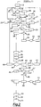
figure 2 shows an outline block diagram of the control process of a dryer, suitable to dehumidify air entering oil expansion vessels used in electrical appliances, according to the invention. - With particular reference to the mentioned
figure 1 , a dryer suitable to dehumidify air entering oil expansion vessels used in electrical appliances, is generically indicated with 10 and basically comprises two dehumidifying vessels or tanks S1, S2, each of which presents a series of micro-openings for entering the air to be dehumidified and an opening for outgoing the dehumidified air and contains absorption means, such as salts or salty granules, suitable to absorb humidity of air coming from the outside and which can be thermally regenerated. - Ventilation means, such as the fans V1 and V2, and heating means, such as resistors R1 and R2, are also provided, placed respectively inside the dehumidifying tanks S1 and S2 and suitable to regenerate the absorption means, as well as detection means, operatively connected with the heating means R1, R2 and suitable to determine the state of saturation of the salts contained into the tanks S1, S2.
- In the invention, the detection means includes a transducer coupled with the dehumidifying tank S1 through fastening means of traditional type, which directly measures the degree of dehumidification of the absorption means contained into the tank S1.
- The transducer consists of an electronic load cell C1, electrically connected with the electric energy power system, of the compression type (converting a force applied into an electrical resistance change) or traction type (converting a stretch into an electrical resistance change).
- The
dryer 10 also comprises an outer protective casing surrounding the dehumidifying tanks S1, S2 and provided with locking flanges, where the openings for outgoing the dehumidified air are made, and one or more sumps for collecting, conveying and discharging outside condensate which leaks, during use, from the inlet micro-openings of the tanks S1, S2. - The collection sump is also provided of an outlet suitable to discharge condensate outside and into which a filtering body is inserted, which is then crossed, in a direction, by the air to be dehumidified entering the tanks S1, S2, and, in the opposite direction, by the condensate to be discharged that is produced, during operation, in the tanks S1, S2.
- Detection by the load cell C1 of a measured mass value M greater than a predefined maximum threshold value Mfs means that the absorption means contained into the tanks S1, S2 have reached a predetermined saturation level and, therefore, resistors R1, R2 are operated in order to regenerate the aforesaid absorption means (salts) to the original state.
- Condensate produced at this stage leaks out from the inlet micro-openings of the side walls of the tanks S1, S2 and reaches the collection sumps, from which it is conveyed outside.
- According to the invention, three resistance temperature detectors (RTD) T1, T2, T3 are also used, consisting of respective temperature sensors placed, respectively, inside the tank S1, inside the tank S2 and inside the cell room C1.
- With particular reference to the attached
figure 2 , the control process, which is the object of the invention, as from astarting phase 11 and a setting at zero phase 12 of the data related to the load cell C1, performs ascreening phase 13 of the temperature values detected by the resistance temperature detector T1 and resistance temperature detector T3 and of the mass value M detected and measured by the load cell C1 and acomparison 14 between the measured mass value M and full scale (maximum) value Mfs. - In case a condition according to which M>MFs is detected, a
first alarm condition 15 occurs, while if M<Mfs (block 16) a further data processing (block 17) occurs with the calculation of the value of the parameter M (detected mass value) and comparison with the value Ms, which is a mass value prefixed by the load cell C1. - Comparing the values M and Ms (block 18), if M<Ms (block 19) the control process returns to the
screening phase 13, while if M>Ms (block 20), for a predetermined time interval ts (with Ms=Ms1 and Ms1 equal to the mass value of operation of the resistor R1), the process performs a check of the cycle of the tank S2 (block 21) and switching the electric valve E1 (block 22) in such a way as to operate the tank S2, after having driven an automatic start (block 23) of the resistor R1. - The switching of the electric valve E1 and consequent activation of the tank S2 occurs even if by checking the cycle of the tank S2 (block 21) it results that the resistor R2 or fan V2 is not operating, while if these components are operating (block 24) the control process gets back to the data processing phase of the
block 17. - The operation phase of the heat cycle of the tank S1 (block 25) determines the operation of the resistor R1 (block 26) and check of such a resistor R1 (block 27) and, therefore, in case of negative check, operation of an alarm (block 28) and, in case of positive check (block 29), starting of a phase of analysis (block 30) of the resistance temperature detector T1 a phase of operation (block 31) and check (block 32) of the fan V1, which, in case of negative check, causes the operation of an another alarm (block 33).
- The analysis phase of the resistance temperature detector T1 (block 30) goes on by putting the temperature value which can be detected by T1 equal to an initial value T1s, when the cycle of the resistor R1 is activated, increasing such a value of a prefixed amount of °C/min (block 34), up to reach (block 35) a value T1s equal to a maximum value T1M of heat temperature of the tank S1 for a maintenance time t1m equal to a predetermined value (and equal, for example, to five hours), to a value T1s equal to 0 (block 36) and to a predetermined and settable value of temperature Y1 which can be detected by the resistance temperature detector T1, whereby the fan V1 is stopped (block 37).
- In such a case, by detecting a pre-settable value Z of the difference between the temperature values which can be detected by the resistance temperature detector T1 and resistance temperature detector T3 (block 38), a phase of data processing T1, T3 and M (stage 39) is reached, whereby if M>Ms1 (block 40) the control process stars again from the switching phase of the electric valve E1 (block 22), while if M<Ms1 (block 41) a switching phase of the electric valve E1 takes place, which allows to operate the tank S1 (phase 42), and a phase of automatic setting at zero (block 43) of the load cell C1, with M=M0 and M0 equal to the mass M after setting at zero, which brings back the control process to the phase of screening of the parameters T1, T3 and M (block 13).
- The phase of switching of the electric valve E1 and operation of the tank S1 (phase 42) causes the operation of the resistor R2 (phase 44) and a check phase (block 45) of the resistor R2, which, in case of negative outcome, determines the operation of an alarm (block 46), while, in case of positive outcome (block 47), determines a phase of analysis of the resistance temperature detector T2 (phase 48) and a phase of operation (phase 49) and check (phase 50) of the fan V2, which, in case of negative check, determines the activation of a related alarm (block 51).
- The activation of the fan V2 (block 49) occurs for a temperature value T2s detected by T2 which can be set and increased of prefixed values of °C/min (block 52) up to a maximum value T2M of heating temperature of the tank S2 (block 53) for a pre-established maximum maintaining time interval t2m (equal, for example, to five hours), as well as up to a temperature value T2S equal to 0 (block 54) and a predetermined settable temperature value Y2 which can be detected by the three Resistance Temperature Detector (RTD) T2 for which the fan V2 is stopped (block 55).
- The features of the dryer, capable of dehumidifying air entering the oil expansion vessels used in electrical appliances, and related control process, as well as the advantages, are clear from the description made.
- It is, finally, clear that several other variations may be made to the dryer and control process in question, without departing from the principle of novelty intrinsic in the inventive idea expressed here, as it is clear that, in the practical implementation of the invention, materials, shapes and sizes of the illustrated details can be changed, as needed, and replaced with others technically equivalent.
Claims (8)
- Process for controlling a dryer (10) suitable for dehumidifying air entering oil expansion vessels used in power electrical appliances, wherein said dryer (10) comprises at least one outer protective casing, provided with locking flanges, where openings for outgoing dehumidified air are provided, and at least one sump for collecting, conveying and discharging outside condensate, wherein said protective casing surrounds two dehumidifying tanks or vessels (S1, S2), each of which has a plurality of micro-openings for entering the air to be dehumidified and one or more openings for outgoing the dehumidified air, each of said two dehumidifying tanks (S1, S2) also containing absorption means suitable to absorb the humidity of air coming from outside and said absorption means being thermally regenerated by means of resistors (R1, R2), each of which placed inside a dehumidifying tank (S1, S2) and connected with a ventilation means (V1, V2) of said tank (S1, S2), wherein at least one load cell (C1) is fixed to a first dehumidifying tank (S1) and is configured to determine the saturation state of said absorption means contained into said first dehumidifying tank (S1) through the conversion of an applied force into an electrical resistance variation, so that a detection by said load cell (C1) of a measured mass value (M) of said absorption means greater than a predefined threshold value (Mfs, MS1) operates said resistors (R1, R2) in order to regenerate said absorption means to the original state, characterized in that said process comprises at least the following steps:- starting (11) and setting at zero (12) data relating to said load cell (C1);- monitoring (13) temperature values detected by a first temperature sensor (T1) placed inside said first dehumidifying tank (S1), by a second temperature sensor (T2) placed inside a second dehumidifying tank (S2) and by a third temperature sensor (T3) placed inside said load cell (C1) and monitoring said mass value (M) detected by said load cell (C1);- comparing (14) said mass value (M) measured by said load cell (C1) with said predefined threshold value (Mfs);- sending an alarm signal (15), in case said measured mass value (M) is greater than said predefined threshold value (Mfs);- data processing (17) for computing a first mass value (M) and for comparing said first mass value (M) with at least one prefixed second mass value (Ms), in case said measured mass value (M) is lower than said predefined threshold value (Mfs) (16);- monitoring (13) said temperature values, in case said measured mass value (M) is lower than said prefixed second mass value (Ms) (18);- performing the following steps in case said measured mass value (M) is greater than said prefixed second mass value (Ms) for a prefixed time limit (ts) (20) and said measured mass value (M) is greater than a third mass value (Ms1) which is equal to a mass value able to operate a first resistor (R1) placed inside said first dehumidifying tank (S1):∘ checking (21) if a second resistor (R2) and/or a ventilation means (V2) placed inside said second dehumidifying tank (S2) is/are operating∘ and switching on an electric valve (E1) for operating (22, 23) said second dehumidifying tank (S2) and said first resistor (R1) coupled with said first dehumidifying tank (S1).
- Process as claimed in claim 1, characterized in that said electric valve (E1) is switched on (22, 23) when said second resistor (R2) and/or said second ventilation means (V2), which are coupled with said second dehumidifying tank (S2), are off.
- Process as claimed in at least one of the previous claims, characterized in that said data processing (17) step is performed in case said second resistor (R2) and/or said second ventilating means (V2), which are coupled with said second dehumidifying tank (S2), are on (24).
- Process as claimed in at least one of the previous claims, characterized in that an alarm is activated (28) in case said first resistor (R1), which is coupled with said first dehumidifying tank (S1), is not operating.
- Process as claimed in claim 2, characterized in that the following steps are performed:- switching on (31) and testing (32) said first ventilating means (V1) coupled with said first dehumidifying tank (S1), in case said first resistor (R1) is operating;- allocating an initial value (T1s), a maximum value (T1M) and a predetermined and settable temperature value (Y1) of a heating temperature of said first dehumidifying tank (S1), said heating temperature being detected by said first temperature sensor (T1), said initial value (T1s) being equal to 0 and corresponding to when said first resistors (R1) is activated and said predetermined and settable temperature value (Y1) corresponding to when said first ventilating means (V1) stops (37);- setting a prefixed time interval (t1 m);- increasing (35) said initial value (T1s) of a prefixed amount of temperature per minute up to (35) a value equal to said maximum value (T1M), for a time interval (T1m) equal to said prefixed time interval which has been set;- varying the temperature value to said initial value (T1s);- varying the temperature value to said predetermined and settable temperature value (Y1),- stopping (37) said first ventilating means (V1).
- Process as claimed in claim 5, characterized in that it includes the further following steps:- detecting (38) a value (Z) equal to the difference between the temperature values detected by said first temperature sensor (T1) placed inside said first dehumidifying tank (S1) and said third temperature sensor (T3) coupled with said load cell (C1);- processing (39) data coming from said first temperature sensor (T1) and from said third temperature sensor (T3), according to which, if said measured mass value (M) is greater than said third mass value (Ms1), said process restarts from said switching on (22) of said second dehumidifying tank (S2), while, if said measured mass value (M) is lower than said third mass value (Ms1), said process provides for a switching phase, which allows to switch on (42) said electric valve (E1) and to provide an automatic zero setting (43) of said load cell (C1), with said measured mass value (M) equal to a fourth mass value (M0), which is equal to the mass value detected by the load cell (C1) after said zero setting, so as to bring said process back to said monitoring step (13) of said temperature values and said measured mass value (M).
- Process as claimed in claim 6, characterized in that said switching on (42) of said electric valve (E1) causes a further switching on (44) and testing (45) phase of said second resistor (R2) coupled with said second dehumidifying tank (S2) in order to check if it is operating or not and an alarm is activated (46) in case during said testing phase (45) of said second resistor (R2), said second resistor (R2) is not operating.
- Process as claimed in claim 7, characterized in that, if said testing phase (45) of said second resistor (R2) reveals that said second resistor (R2) is operating, said process provides for:- switching on (49) and testing (50) said second ventilating means (V2) coupled with said second dehumidifying tank (S2) and- allocating a prefixed heating temperature value (T2s), a maximum heating temperature value (T2M), a predetermined third heating temperature value (T2S) and a settable heating temperature value (Y2) by means of said temperature sensor (T2) of said second dehumidifying tank (S2), the third heating temperature value (T2S) being equal to 0 and corresponding to when said first resistor (R1) is activated and said settable heating temperature value (Y2) corresponding to when second ventilating means (V2) stops (55),- setting a pre-established maximum interval of time (t2m);- incrementing (52) said prefixed heating temperature value (T2s) with predetermined ranges of value of temperature per minute up (53) to said maximum heating temperature value (T2M), for a time interval equal to said pre-established maximum interval of time (t2m),- varying the temperature value (54) up to said third heating temperature value (T2S) and/or equal to said settable heating temperature value (Y2).
Applications Claiming Priority (2)
| Application Number | Priority Date | Filing Date | Title |
|---|---|---|---|
| IT000031A ITVI20100031A1 (en) | 2010-02-12 | 2010-02-12 | PROCEDURE FOR THE CONTROL OF A DRYER TO DEHUMIDIFY THE AIR INTENDED FOR OIL EXPANSION VESSELS USED IN ELECTRICAL EQUIPMENT |
| PCT/IT2011/000035 WO2011099046A1 (en) | 2010-02-12 | 2011-02-10 | Process for controlling dryer capable of dehumidifying air entering the oil expansion vessels used in electrical appliances |
Publications (2)
| Publication Number | Publication Date |
|---|---|
| EP2533880A1 EP2533880A1 (en) | 2012-12-19 |
| EP2533880B1 true EP2533880B1 (en) | 2021-08-04 |
Family
ID=42735229
Family Applications (1)
| Application Number | Title | Priority Date | Filing Date |
|---|---|---|---|
| EP11709214.8A Active EP2533880B1 (en) | 2010-02-12 | 2011-02-10 | Process for controlling dryer capable of dehumidifying air entering the oil expansion vessels used in electrical appliances |
Country Status (5)
| Country | Link |
|---|---|
| US (1) | US20130133221A1 (en) |
| EP (1) | EP2533880B1 (en) |
| CN (1) | CN102811792A (en) |
| IT (1) | ITVI20100031A1 (en) |
| WO (1) | WO2011099046A1 (en) |
Families Citing this family (3)
| Publication number | Priority date | Publication date | Assignee | Title |
|---|---|---|---|---|
| WO2017002128A1 (en) | 2015-07-01 | 2017-01-05 | Balkrishna Potnis Shrikant | Regenerating breathers system |
| CN110400678B (en) * | 2019-06-20 | 2024-08-30 | 国网上海市电力公司 | A self-healing method for a moisture absorption device of a transformer respirator |
| CN116492824A (en) * | 2023-06-29 | 2023-07-28 | 常州长创力智能科技有限公司 | Renewable transformer dehumidifying filter and control method thereof |
Family Cites Families (14)
| Publication number | Priority date | Publication date | Assignee | Title |
|---|---|---|---|---|
| JPS57153721A (en) * | 1981-03-18 | 1982-09-22 | Toshiba Corp | Air dehumidifying apparatus for ozone generator |
| JPS60178009A (en) * | 1984-02-25 | 1985-09-12 | Color Toronitsuku Kk | Method and apparatus for generation of high temperature dehumidified air for drying synthetic resin |
| DE3901779C2 (en) * | 1989-01-21 | 1997-08-14 | Somos Gmbh | Method and device for adsorbing moisture from gases, especially air |
| US5199964A (en) * | 1989-01-21 | 1993-04-06 | Graeff Roderich | Method and apparatus for adsorbing moisture from gases especially air |
| GB2232093A (en) * | 1989-05-17 | 1990-12-05 | Mcgill Europ Limited | Hydrocarbon vapour recovery. |
| US5768897A (en) * | 1992-06-16 | 1998-06-23 | Universal Dynamics Corporation | Air drying apparatus and method with high ratio gas flow to absorber weight |
| FR2818920B1 (en) * | 2000-12-29 | 2003-09-26 | Air Liquide | METHOD FOR TREATING A GAS BY ABSORPTION AND CORRESPONDING INSTALLATION |
| EP1313112B1 (en) * | 2001-11-13 | 2004-03-17 | Messko Albert Hauser GmbH & Co. KG | Air dehumidifier for oil insulated transformers, choke coils as well as tap changers |
| AT412999B (en) * | 2002-11-12 | 2005-09-26 | Wiedl Alfred | APPENDIX FOR DRYING GOODS |
| DE10357085B3 (en) | 2003-12-06 | 2005-03-17 | Maschinenfabrik Reinhausen Gmbh | Air de-humidifying method for oil-insulated transformer, choke coil or stepping switch uses humidity-absorbing granules heated by electric heating device |
| ITVR20060030A1 (en) * | 2006-02-10 | 2007-08-11 | Moretto Spa | SYSTEM AND DEHUMIDIFICATION PROCEDURE WITH FLEXIBLE OPERATION PARTICULARLY FOR GRANULAR MATERIALS. |
| US20070272083A1 (en) * | 2006-03-30 | 2007-11-29 | Ross Hoge | Filter saturation control system |
| ITVI20070222A1 (en) * | 2007-08-07 | 2009-02-08 | Comem Spa | PERFECT DRYER TO DEHUMIDIFY THE AIR INTENDED FOR OIL EXPANSION VESSELS USED IN ELECTRICAL EQUIPMENT. |
| WO2010102308A1 (en) * | 2009-03-06 | 2010-09-10 | Sensortech Corporation | Load cell |
-
2010
- 2010-02-12 IT IT000031A patent/ITVI20100031A1/en unknown
-
2011
- 2011-02-10 EP EP11709214.8A patent/EP2533880B1/en active Active
- 2011-02-10 WO PCT/IT2011/000035 patent/WO2011099046A1/en not_active Ceased
- 2011-02-10 US US13/578,072 patent/US20130133221A1/en not_active Abandoned
- 2011-02-10 CN CN2011800089378A patent/CN102811792A/en active Pending
Non-Patent Citations (1)
| Title |
|---|
| None * |
Also Published As
| Publication number | Publication date |
|---|---|
| EP2533880A1 (en) | 2012-12-19 |
| CN102811792A (en) | 2012-12-05 |
| ITVI20100031A1 (en) | 2011-08-13 |
| WO2011099046A1 (en) | 2011-08-18 |
| US20130133221A1 (en) | 2013-05-30 |
Similar Documents
| Publication | Publication Date | Title |
|---|---|---|
| TWI868879B (en) | Control method and apparus for clothing processing apparatus, clothing processing apparatus and storage medium | |
| EP2175965B1 (en) | Improved drier for dehumidifying the air intended for oil expansion tank used in electrical equipments | |
| CN103090460A (en) | Method and device for discharging condensate water for heating, ventilating or air conditioning system | |
| CN102154805A (en) | Clothes dryer air duct jam judging method and clothes dryer | |
| CN103882664B (en) | Clothes dryer and working method thereof | |
| WO2016019661A1 (en) | Drainage device and method and dehumidifier | |
| JP2013252474A (en) | Gas dryer for electric machine | |
| US20130133221A1 (en) | Process for controlling dryer capable of dehumidifying air entering the oil expansion vessels used in electrical appliances | |
| CN113790572B (en) | Refrigerator control method and device, storage medium and refrigerator | |
| JP2012076060A (en) | Dehumidifying apparatus | |
| EP3086060A1 (en) | Defrosting method and device for refrigerating or air conditioning apparatus | |
| JP2009171998A (en) | Washing and drying machine | |
| CN205119419U (en) | Cabinet air conditioning that no comdenstion water discharged | |
| JP2011158121A (en) | Air conditioner | |
| JP2014181851A (en) | Dehumidifier | |
| CN103837313A (en) | Automatic detection system and method for steam cabinet air tightness | |
| CN107951378B (en) | Pressure cooking appliance and control method thereof | |
| CN104265612A (en) | Water pump control method | |
| CN105318509B (en) | The control system and control method of cabinet air conditioner | |
| JP2016188731A (en) | Air conditioner | |
| KR100607130B1 (en) | Fault notification device and method of steam generator | |
| KR20140076662A (en) | Apparatus for air conditioner and method for draining the same | |
| JP7455048B2 (en) | air conditioner | |
| JP7781115B2 (en) | Air Treatment Equipment | |
| CN112567887B (en) | Method for operating a domestic cooking appliance and domestic cooking appliance |
Legal Events
| Date | Code | Title | Description |
|---|---|---|---|
| PUAI | Public reference made under article 153(3) epc to a published international application that has entered the european phase |
Free format text: ORIGINAL CODE: 0009012 |
|
| 17P | Request for examination filed |
Effective date: 20120720 |
|
| AK | Designated contracting states |
Kind code of ref document: A1 Designated state(s): AL AT BE BG CH CY CZ DE DK EE ES FI FR GB GR HR HU IE IS IT LI LT LU LV MC MK MT NL NO PL PT RO RS SE SI SK SM TR |
|
| DAX | Request for extension of the european patent (deleted) | ||
| RAP1 | Party data changed (applicant data changed or rights of an application transferred) |
Owner name: ABB SCHWEIZ AG |
|
| STAA | Information on the status of an ep patent application or granted ep patent |
Free format text: STATUS: EXAMINATION IS IN PROGRESS |
|
| 17Q | First examination report despatched |
Effective date: 20181015 |
|
| RAP1 | Party data changed (applicant data changed or rights of an application transferred) |
Owner name: ABB SCHWEIZ AG |
|
| RAP1 | Party data changed (applicant data changed or rights of an application transferred) |
Owner name: ABB POWER GRIDS SWITZERLAND AG |
|
| RIC1 | Information provided on ipc code assigned before grant |
Ipc: B01D 53/26 20060101AFI20210115BHEP Ipc: B01D 53/04 20060101ALI20210115BHEP Ipc: H01F 27/14 20060101ALI20210115BHEP Ipc: G01N 5/02 20060101ALI20210115BHEP |
|
| GRAP | Despatch of communication of intention to grant a patent |
Free format text: ORIGINAL CODE: EPIDOSNIGR1 |
|
| STAA | Information on the status of an ep patent application or granted ep patent |
Free format text: STATUS: GRANT OF PATENT IS INTENDED |
|
| INTG | Intention to grant announced |
Effective date: 20210226 |
|
| RAP1 | Party data changed (applicant data changed or rights of an application transferred) |
Owner name: COMEM S.R.L. |
|
| RIN1 | Information on inventor provided before grant (corrected) |
Inventor name: CAROLLO, CARLO Inventor name: TONIN, ANDREA |
|
| GRAS | Grant fee paid |
Free format text: ORIGINAL CODE: EPIDOSNIGR3 |
|
| GRAA | (expected) grant |
Free format text: ORIGINAL CODE: 0009210 |
|
| STAA | Information on the status of an ep patent application or granted ep patent |
Free format text: STATUS: THE PATENT HAS BEEN GRANTED |
|
| AK | Designated contracting states |
Kind code of ref document: B1 Designated state(s): AL AT BE BG CH CY CZ DE DK EE ES FI FR GB GR HR HU IE IS IT LI LT LU LV MC MK MT NL NO PL PT RO RS SE SI SK SM TR |
|
| REG | Reference to a national code |
Ref country code: GB Ref legal event code: FG4D |
|
| REG | Reference to a national code |
Ref country code: AT Ref legal event code: REF Ref document number: 1416389 Country of ref document: AT Kind code of ref document: T Effective date: 20210815 |
|
| REG | Reference to a national code |
Ref country code: CH Ref legal event code: EP |
|
| REG | Reference to a national code |
Ref country code: DE Ref legal event code: R096 Ref document number: 602011071487 Country of ref document: DE |
|
| REG | Reference to a national code |
Ref country code: IE Ref legal event code: FG4D |
|
| REG | Reference to a national code |
Ref country code: LT Ref legal event code: MG9D |
|
| REG | Reference to a national code |
Ref country code: NL Ref legal event code: MP Effective date: 20210804 |
|
| REG | Reference to a national code |
Ref country code: AT Ref legal event code: MK05 Ref document number: 1416389 Country of ref document: AT Kind code of ref document: T Effective date: 20210804 |
|
| PG25 | Lapsed in a contracting state [announced via postgrant information from national office to epo] |
Ref country code: SE Free format text: LAPSE BECAUSE OF FAILURE TO SUBMIT A TRANSLATION OF THE DESCRIPTION OR TO PAY THE FEE WITHIN THE PRESCRIBED TIME-LIMIT Effective date: 20210804 Ref country code: HR Free format text: LAPSE BECAUSE OF FAILURE TO SUBMIT A TRANSLATION OF THE DESCRIPTION OR TO PAY THE FEE WITHIN THE PRESCRIBED TIME-LIMIT Effective date: 20210804 Ref country code: NO Free format text: LAPSE BECAUSE OF FAILURE TO SUBMIT A TRANSLATION OF THE DESCRIPTION OR TO PAY THE FEE WITHIN THE PRESCRIBED TIME-LIMIT Effective date: 20211104 Ref country code: PT Free format text: LAPSE BECAUSE OF FAILURE TO SUBMIT A TRANSLATION OF THE DESCRIPTION OR TO PAY THE FEE WITHIN THE PRESCRIBED TIME-LIMIT Effective date: 20211206 Ref country code: RS Free format text: LAPSE BECAUSE OF FAILURE TO SUBMIT A TRANSLATION OF THE DESCRIPTION OR TO PAY THE FEE WITHIN THE PRESCRIBED TIME-LIMIT Effective date: 20210804 Ref country code: ES Free format text: LAPSE BECAUSE OF FAILURE TO SUBMIT A TRANSLATION OF THE DESCRIPTION OR TO PAY THE FEE WITHIN THE PRESCRIBED TIME-LIMIT Effective date: 20210804 Ref country code: FI Free format text: LAPSE BECAUSE OF FAILURE TO SUBMIT A TRANSLATION OF THE DESCRIPTION OR TO PAY THE FEE WITHIN THE PRESCRIBED TIME-LIMIT Effective date: 20210804 Ref country code: AT Free format text: LAPSE BECAUSE OF FAILURE TO SUBMIT A TRANSLATION OF THE DESCRIPTION OR TO PAY THE FEE WITHIN THE PRESCRIBED TIME-LIMIT Effective date: 20210804 Ref country code: BG Free format text: LAPSE BECAUSE OF FAILURE TO SUBMIT A TRANSLATION OF THE DESCRIPTION OR TO PAY THE FEE WITHIN THE PRESCRIBED TIME-LIMIT Effective date: 20211104 Ref country code: LT Free format text: LAPSE BECAUSE OF FAILURE TO SUBMIT A TRANSLATION OF THE DESCRIPTION OR TO PAY THE FEE WITHIN THE PRESCRIBED TIME-LIMIT Effective date: 20210804 |
|
| PG25 | Lapsed in a contracting state [announced via postgrant information from national office to epo] |
Ref country code: PL Free format text: LAPSE BECAUSE OF FAILURE TO SUBMIT A TRANSLATION OF THE DESCRIPTION OR TO PAY THE FEE WITHIN THE PRESCRIBED TIME-LIMIT Effective date: 20210804 Ref country code: LV Free format text: LAPSE BECAUSE OF FAILURE TO SUBMIT A TRANSLATION OF THE DESCRIPTION OR TO PAY THE FEE WITHIN THE PRESCRIBED TIME-LIMIT Effective date: 20210804 Ref country code: GR Free format text: LAPSE BECAUSE OF FAILURE TO SUBMIT A TRANSLATION OF THE DESCRIPTION OR TO PAY THE FEE WITHIN THE PRESCRIBED TIME-LIMIT Effective date: 20211105 |
|
| PG25 | Lapsed in a contracting state [announced via postgrant information from national office to epo] |
Ref country code: NL Free format text: LAPSE BECAUSE OF FAILURE TO SUBMIT A TRANSLATION OF THE DESCRIPTION OR TO PAY THE FEE WITHIN THE PRESCRIBED TIME-LIMIT Effective date: 20210804 |
|
| PG25 | Lapsed in a contracting state [announced via postgrant information from national office to epo] |
Ref country code: DK Free format text: LAPSE BECAUSE OF FAILURE TO SUBMIT A TRANSLATION OF THE DESCRIPTION OR TO PAY THE FEE WITHIN THE PRESCRIBED TIME-LIMIT Effective date: 20210804 |
|
| REG | Reference to a national code |
Ref country code: DE Ref legal event code: R097 Ref document number: 602011071487 Country of ref document: DE |
|
| PG25 | Lapsed in a contracting state [announced via postgrant information from national office to epo] |
Ref country code: SM Free format text: LAPSE BECAUSE OF FAILURE TO SUBMIT A TRANSLATION OF THE DESCRIPTION OR TO PAY THE FEE WITHIN THE PRESCRIBED TIME-LIMIT Effective date: 20210804 Ref country code: SK Free format text: LAPSE BECAUSE OF FAILURE TO SUBMIT A TRANSLATION OF THE DESCRIPTION OR TO PAY THE FEE WITHIN THE PRESCRIBED TIME-LIMIT Effective date: 20210804 Ref country code: RO Free format text: LAPSE BECAUSE OF FAILURE TO SUBMIT A TRANSLATION OF THE DESCRIPTION OR TO PAY THE FEE WITHIN THE PRESCRIBED TIME-LIMIT Effective date: 20210804 Ref country code: EE Free format text: LAPSE BECAUSE OF FAILURE TO SUBMIT A TRANSLATION OF THE DESCRIPTION OR TO PAY THE FEE WITHIN THE PRESCRIBED TIME-LIMIT Effective date: 20210804 Ref country code: CZ Free format text: LAPSE BECAUSE OF FAILURE TO SUBMIT A TRANSLATION OF THE DESCRIPTION OR TO PAY THE FEE WITHIN THE PRESCRIBED TIME-LIMIT Effective date: 20210804 Ref country code: AL Free format text: LAPSE BECAUSE OF FAILURE TO SUBMIT A TRANSLATION OF THE DESCRIPTION OR TO PAY THE FEE WITHIN THE PRESCRIBED TIME-LIMIT Effective date: 20210804 |
|
| PLBE | No opposition filed within time limit |
Free format text: ORIGINAL CODE: 0009261 |
|
| STAA | Information on the status of an ep patent application or granted ep patent |
Free format text: STATUS: NO OPPOSITION FILED WITHIN TIME LIMIT |
|
| 26N | No opposition filed |
Effective date: 20220506 |
|
| PG25 | Lapsed in a contracting state [announced via postgrant information from national office to epo] |
Ref country code: SI Free format text: LAPSE BECAUSE OF FAILURE TO SUBMIT A TRANSLATION OF THE DESCRIPTION OR TO PAY THE FEE WITHIN THE PRESCRIBED TIME-LIMIT Effective date: 20210804 |
|
| PG25 | Lapsed in a contracting state [announced via postgrant information from national office to epo] |
Ref country code: MC Free format text: LAPSE BECAUSE OF FAILURE TO SUBMIT A TRANSLATION OF THE DESCRIPTION OR TO PAY THE FEE WITHIN THE PRESCRIBED TIME-LIMIT Effective date: 20210804 |
|
| REG | Reference to a national code |
Ref country code: CH Ref legal event code: PL |
|
| REG | Reference to a national code |
Ref country code: BE Ref legal event code: MM Effective date: 20220228 |
|
| GBPC | Gb: european patent ceased through non-payment of renewal fee |
Effective date: 20220210 |
|
| PG25 | Lapsed in a contracting state [announced via postgrant information from national office to epo] |
Ref country code: LU Free format text: LAPSE BECAUSE OF NON-PAYMENT OF DUE FEES Effective date: 20220210 |
|
| PG25 | Lapsed in a contracting state [announced via postgrant information from national office to epo] |
Ref country code: FR Free format text: LAPSE BECAUSE OF NON-PAYMENT OF DUE FEES Effective date: 20220228 |
|
| PG25 | Lapsed in a contracting state [announced via postgrant information from national office to epo] |
Ref country code: LI Free format text: LAPSE BECAUSE OF NON-PAYMENT OF DUE FEES Effective date: 20220228 Ref country code: GB Free format text: LAPSE BECAUSE OF NON-PAYMENT OF DUE FEES Effective date: 20220210 Ref country code: CH Free format text: LAPSE BECAUSE OF NON-PAYMENT OF DUE FEES Effective date: 20220228 |
|
| PG25 | Lapsed in a contracting state [announced via postgrant information from national office to epo] |
Ref country code: BE Free format text: LAPSE BECAUSE OF NON-PAYMENT OF DUE FEES Effective date: 20220228 |
|
| P01 | Opt-out of the competence of the unified patent court (upc) registered |
Effective date: 20230519 |
|
| PG25 | Lapsed in a contracting state [announced via postgrant information from national office to epo] |
Ref country code: HU Free format text: LAPSE BECAUSE OF FAILURE TO SUBMIT A TRANSLATION OF THE DESCRIPTION OR TO PAY THE FEE WITHIN THE PRESCRIBED TIME-LIMIT; INVALID AB INITIO Effective date: 20110210 |
|
| PG25 | Lapsed in a contracting state [announced via postgrant information from national office to epo] |
Ref country code: MK Free format text: LAPSE BECAUSE OF FAILURE TO SUBMIT A TRANSLATION OF THE DESCRIPTION OR TO PAY THE FEE WITHIN THE PRESCRIBED TIME-LIMIT Effective date: 20210804 Ref country code: CY Free format text: LAPSE BECAUSE OF FAILURE TO SUBMIT A TRANSLATION OF THE DESCRIPTION OR TO PAY THE FEE WITHIN THE PRESCRIBED TIME-LIMIT Effective date: 20210804 |
|
| PG25 | Lapsed in a contracting state [announced via postgrant information from national office to epo] |
Ref country code: MT Free format text: LAPSE BECAUSE OF FAILURE TO SUBMIT A TRANSLATION OF THE DESCRIPTION OR TO PAY THE FEE WITHIN THE PRESCRIBED TIME-LIMIT Effective date: 20210804 |
|
| PGFP | Annual fee paid to national office [announced via postgrant information from national office to epo] |
Ref country code: IE Payment date: 20251209 Year of fee payment: 16 |
|
| PGFP | Annual fee paid to national office [announced via postgrant information from national office to epo] |
Ref country code: DE Payment date: 20251216 Year of fee payment: 16 |
|
| PGFP | Annual fee paid to national office [announced via postgrant information from national office to epo] |
Ref country code: IT Payment date: 20260115 Year of fee payment: 16 |
|
| PGFP | Annual fee paid to national office [announced via postgrant information from national office to epo] |
Ref country code: TR Payment date: 20260209 Year of fee payment: 16 |