EP2533323A1 - Battery, battery production device, and battery production method - Google Patents
Battery, battery production device, and battery production method Download PDFInfo
- Publication number
- EP2533323A1 EP2533323A1 EP11737212A EP11737212A EP2533323A1 EP 2533323 A1 EP2533323 A1 EP 2533323A1 EP 11737212 A EP11737212 A EP 11737212A EP 11737212 A EP11737212 A EP 11737212A EP 2533323 A1 EP2533323 A1 EP 2533323A1
- Authority
- EP
- European Patent Office
- Prior art keywords
- cover
- casing body
- battery
- outside
- fitting
- Prior art date
- Legal status (The legal status is an assumption and is not a legal conclusion. Google has not performed a legal analysis and makes no representation as to the accuracy of the status listed.)
- Withdrawn
Links
- 238000004519 manufacturing process Methods 0.000 title claims description 33
- 238000003466 welding Methods 0.000 claims abstract description 44
- 229910052751 metal Inorganic materials 0.000 abstract description 15
- 239000002184 metal Substances 0.000 abstract description 15
- 238000000034 method Methods 0.000 description 20
- HBBGRARXTFLTSG-UHFFFAOYSA-N Lithium ion Chemical compound [Li+] HBBGRARXTFLTSG-UHFFFAOYSA-N 0.000 description 9
- 239000003792 electrolyte Substances 0.000 description 9
- 229910001416 lithium ion Inorganic materials 0.000 description 9
- 238000010586 diagram Methods 0.000 description 6
- 238000003825 pressing Methods 0.000 description 4
- 238000002347 injection Methods 0.000 description 3
- 239000007924 injection Substances 0.000 description 3
- 230000003287 optical effect Effects 0.000 description 2
- 229910052782 aluminium Inorganic materials 0.000 description 1
- XAGFODPZIPBFFR-UHFFFAOYSA-N aluminium Chemical compound [Al] XAGFODPZIPBFFR-UHFFFAOYSA-N 0.000 description 1
- 239000011248 coating agent Substances 0.000 description 1
- 238000000576 coating method Methods 0.000 description 1
- 238000005520 cutting process Methods 0.000 description 1
- 230000007547 defect Effects 0.000 description 1
- 230000000694 effects Effects 0.000 description 1
- 239000008151 electrolyte solution Substances 0.000 description 1
- 239000011888 foil Substances 0.000 description 1
- 238000012986 modification Methods 0.000 description 1
- 230000004048 modification Effects 0.000 description 1
- 230000002093 peripheral effect Effects 0.000 description 1
- 239000011347 resin Substances 0.000 description 1
- 229920005989 resin Polymers 0.000 description 1
- 238000007789 sealing Methods 0.000 description 1
- 239000011343 solid material Substances 0.000 description 1
- 239000000243 solution Substances 0.000 description 1
- 238000003860 storage Methods 0.000 description 1
Images




Classifications
-
- H—ELECTRICITY
- H01—ELECTRIC ELEMENTS
- H01M—PROCESSES OR MEANS, e.g. BATTERIES, FOR THE DIRECT CONVERSION OF CHEMICAL ENERGY INTO ELECTRICAL ENERGY
- H01M50/00—Constructional details or processes of manufacture of the non-active parts of electrochemical cells other than fuel cells, e.g. hybrid cells
- H01M50/10—Primary casings; Jackets or wrappings
- H01M50/147—Lids or covers
-
- H—ELECTRICITY
- H01—ELECTRIC ELEMENTS
- H01M—PROCESSES OR MEANS, e.g. BATTERIES, FOR THE DIRECT CONVERSION OF CHEMICAL ENERGY INTO ELECTRICAL ENERGY
- H01M10/00—Secondary cells; Manufacture thereof
- H01M10/04—Construction or manufacture in general
- H01M10/0413—Large-sized flat cells or batteries for motive or stationary systems with plate-like electrodes
-
- H—ELECTRICITY
- H01—ELECTRIC ELEMENTS
- H01M—PROCESSES OR MEANS, e.g. BATTERIES, FOR THE DIRECT CONVERSION OF CHEMICAL ENERGY INTO ELECTRICAL ENERGY
- H01M10/00—Secondary cells; Manufacture thereof
- H01M10/05—Accumulators with non-aqueous electrolyte
- H01M10/058—Construction or manufacture
- H01M10/0585—Construction or manufacture of accumulators having only flat construction elements, i.e. flat positive electrodes, flat negative electrodes and flat separators
-
- H—ELECTRICITY
- H01—ELECTRIC ELEMENTS
- H01M—PROCESSES OR MEANS, e.g. BATTERIES, FOR THE DIRECT CONVERSION OF CHEMICAL ENERGY INTO ELECTRICAL ENERGY
- H01M50/00—Constructional details or processes of manufacture of the non-active parts of electrochemical cells other than fuel cells, e.g. hybrid cells
- H01M50/10—Primary casings; Jackets or wrappings
- H01M50/147—Lids or covers
- H01M50/166—Lids or covers characterised by the methods of assembling casings with lids
- H01M50/169—Lids or covers characterised by the methods of assembling casings with lids by welding, brazing or soldering
-
- H—ELECTRICITY
- H01—ELECTRIC ELEMENTS
- H01M—PROCESSES OR MEANS, e.g. BATTERIES, FOR THE DIRECT CONVERSION OF CHEMICAL ENERGY INTO ELECTRICAL ENERGY
- H01M50/00—Constructional details or processes of manufacture of the non-active parts of electrochemical cells other than fuel cells, e.g. hybrid cells
- H01M50/10—Primary casings; Jackets or wrappings
- H01M50/172—Arrangements of electric connectors penetrating the casing
- H01M50/174—Arrangements of electric connectors penetrating the casing adapted for the shape of the cells
- H01M50/176—Arrangements of electric connectors penetrating the casing adapted for the shape of the cells for prismatic or rectangular cells
-
- H—ELECTRICITY
- H01—ELECTRIC ELEMENTS
- H01M—PROCESSES OR MEANS, e.g. BATTERIES, FOR THE DIRECT CONVERSION OF CHEMICAL ENERGY INTO ELECTRICAL ENERGY
- H01M50/00—Constructional details or processes of manufacture of the non-active parts of electrochemical cells other than fuel cells, e.g. hybrid cells
- H01M50/50—Current conducting connections for cells or batteries
- H01M50/528—Fixed electrical connections, i.e. not intended for disconnection
-
- H—ELECTRICITY
- H01—ELECTRIC ELEMENTS
- H01M—PROCESSES OR MEANS, e.g. BATTERIES, FOR THE DIRECT CONVERSION OF CHEMICAL ENERGY INTO ELECTRICAL ENERGY
- H01M10/00—Secondary cells; Manufacture thereof
- H01M10/05—Accumulators with non-aqueous electrolyte
- H01M10/052—Li-accumulators
-
- Y—GENERAL TAGGING OF NEW TECHNOLOGICAL DEVELOPMENTS; GENERAL TAGGING OF CROSS-SECTIONAL TECHNOLOGIES SPANNING OVER SEVERAL SECTIONS OF THE IPC; TECHNICAL SUBJECTS COVERED BY FORMER USPC CROSS-REFERENCE ART COLLECTIONS [XRACs] AND DIGESTS
- Y02—TECHNOLOGIES OR APPLICATIONS FOR MITIGATION OR ADAPTATION AGAINST CLIMATE CHANGE
- Y02E—REDUCTION OF GREENHOUSE GAS [GHG] EMISSIONS, RELATED TO ENERGY GENERATION, TRANSMISSION OR DISTRIBUTION
- Y02E60/00—Enabling technologies; Technologies with a potential or indirect contribution to GHG emissions mitigation
- Y02E60/10—Energy storage using batteries
-
- Y—GENERAL TAGGING OF NEW TECHNOLOGICAL DEVELOPMENTS; GENERAL TAGGING OF CROSS-SECTIONAL TECHNOLOGIES SPANNING OVER SEVERAL SECTIONS OF THE IPC; TECHNICAL SUBJECTS COVERED BY FORMER USPC CROSS-REFERENCE ART COLLECTIONS [XRACs] AND DIGESTS
- Y02—TECHNOLOGIES OR APPLICATIONS FOR MITIGATION OR ADAPTATION AGAINST CLIMATE CHANGE
- Y02P—CLIMATE CHANGE MITIGATION TECHNOLOGIES IN THE PRODUCTION OR PROCESSING OF GOODS
- Y02P70/00—Climate change mitigation technologies in the production process for final industrial or consumer products
- Y02P70/50—Manufacturing or production processes characterised by the final manufactured product
-
- Y—GENERAL TAGGING OF NEW TECHNOLOGICAL DEVELOPMENTS; GENERAL TAGGING OF CROSS-SECTIONAL TECHNOLOGIES SPANNING OVER SEVERAL SECTIONS OF THE IPC; TECHNICAL SUBJECTS COVERED BY FORMER USPC CROSS-REFERENCE ART COLLECTIONS [XRACs] AND DIGESTS
- Y10—TECHNICAL SUBJECTS COVERED BY FORMER USPC
- Y10T—TECHNICAL SUBJECTS COVERED BY FORMER US CLASSIFICATION
- Y10T29/00—Metal working
- Y10T29/53—Means to assemble or disassemble
- Y10T29/5313—Means to assemble electrical device
- Y10T29/53135—Storage cell or battery
Definitions
- the present invention relates to a battery, a battery manufacturing machine, and a battery manufacturing method.
- Priority is claimed on Japanese Patent Application No. 2010-020325, filed on February 1, 2010 , the content of which is incorporated herein by reference.
- a unit cell or an assembled battery has been used as a power supply of an electronic device or the like.
- a secondary battery such as a lithium ion secondary battery with high energy density has been developed.
- the unit cell or the assembled battery has been used as a part of a home electrical storage device or as a power supply of an electric vehicle, because they have high energy density.
- the secondary battery includes a battery case storing an electrolyte, an electrode sheet being soaked in the electrolyte, and an electrode terminal being electrically connected to the electrode sheet. And, the electrode terminal is arranged on the battery case.
- the battery case includes, for example, the casing body having an opening, and a cover closing the opening. The electrode plate is inserted in the casing body from the opening and the cover is attached to close and to seal the opening hermetically.
- Patent Document 1 As a method of attaching the cover to the casing body, a technique disclosed in Patent Document 1 may be exemplified.
- the cover is fitted to the inside of the opening of the casing body.
- the method of fitting the cover to the opening as described in Patent Document 1 is defined as "inside-fitting".
- the cover and the casing body is welded and connected by a laser welding machine, after the edge of the casing body and the cover are leveled by the inside-fitting.
- the inside-fitting indicates a technique to fit the cover into the battery case. Therefore the cover has an outer diameter substantially equal to the diameter of the opening of the casing body.
- Patent Document 1 Japanese Patent Application Laid-Open No. 2003-181666
- Patent Document 1 because the cover is inside-fitted to the casing body, there are problems as below.
- the cover fits to the opening by the inside-fitting the cover may fall into the casing body erroneously during the inside-fitting.
- the edge of the casing body around the opening may be formed to be thinner at the upper part of the main body than the other parts in order that the cover is held by other parts. According to this method, it is possible to prevent the cover from falling into the casing body, but productivity is may become worse because highly precise cutting is necessary for making the shape of the upper part.
- Patent Document 1 the casing body and the cover are welded each other while the opening is arranged at the upper side of casing body. It is a second Problem that the method, the molten metal by the welding flows into the inside of the casing body and the molten metal contact the inside of the battery case, a defect such as short-circuit may occur.
- the invention is made to solve these problems described above, and it is an object of the invention to provide the battery which is assembled at low cost, and to provide a manufacturing machine of battery.
- a battery comprising: a casing body having an opening opened from at least one edge thereof; and a cover having an outer diameter larger than the diameter of the opening and covering the opening; wherein the cover is fitted to the outside of the casing body by an outside-fitting, and the edge of the cover and the casing body are welded to each other to form a battery case.
- the cover is fitted to the casing body to the casing body by the outside-fitting described later, the cover does not fall into the casing body when the cover is fitted to the casing body. Therefore, compared with the inside-fitting, it is possible to obtain the battery having the cover fitted to the casing body easily. Therefore, the battery may be made at low cost. Further, because the cover is welded to the outer peripheral surface of the casing body, the metal melted during the welding of the cover does not flow into the inside of the casing body. Therefore, the short-circuit is not easily occurred.
- the battery manufacturing machine includes: a support table on which the battery is placed; a reversing mechanism that holds and reverses the casing body; a welding machine for welding the edge of the cover and the casing body to each other; and a controller that controls the reversing mechanism and the welding machine, wherein the support table is provided with an recess part that receives an electrode terminal of the battery, and the controller controls the reversing mechanism in order that the casing body is reversed and put on the support table for the electrode terminal to received in the recess part, and the controller controls the welding machine in order that the edge of the cover and the casing body are welded to each other by the welding machine.
- a battery manufacturing method of manufacturing the battery according to the invention comprising: fitting the cover to the outside of the casing body by the outside-fitting; reversing the casing body having the cover fitted to the outside thereof; and welding the edge of the cover and the battery body to each other after the reversing.
- the cover is fitted to the outside of the casing body, the casing body and the cover is reversed, and the cover and the casing body are welding each other. Therefore, it is possible to prevent the cover from falling in the casing body. And, it is possible to easily and reliably fit the cover to the casing body, and to efficiently and highly-precisely weld the cover to the casing body for sealing the battery tightly. Further, because the metal melted during the welding does not stream into the inside of the casing body, an excellent battery may be manufactured. Further, it is possible to manufacture an excellent battery at low cost.
- the cover is fitted and welded to the outside of the casing body, it is possible to reduce the assembly cost of the battery and prevent molten metal from entering the casing body during the welding. Further, it is possible to manufacture the excellent battery at low cost.
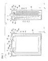
- FIG. 1 illustrates a perspective view of a schematic configuration of a secondary battery 1 as one embodiment of the invention
- FIG. 2A illustrates a cross-sectional view taken along the line A-A' of FIG. 1
- FIG. 2B illustrates a cross-sectional view taken along the line B-B' of FIG. 1
- the secondary battery 1 of the embodiment is a lithium ion secondary battery which is a stacked type, but the application scope of the invention is not limited to the lithium ion secondary battery.
- the invention may be applied to a battery such as a wound lithium ion secondary battery which is a wound type, a secondary battery other than the lithium ion secondary battery, or a primary battery.
- the secondary battery 1 includes a battery case 10, and the electrode terminals (i.e., a positive electrode terminal 11 and a negative electrode terminal 12).
- the battery case 10 includes a casing body 20 of which one end is opened and a cover 21 which closes the opening of the casing body 20.
- the battery case 10 is a metallic case made of aluminum in a substantially rectangular parallelepiped shape.
- the outer shape of the battery case 10 may be a shape other than the substantially rectangular column shape (e.g., a substantially cylindrical shape).
- the casing body 20 has a shape which has a wall surface surrounding the periphery of an axis in an annular shape (e.g., a cylindrical shape or a rectangular column shape).
- the outline of the casing body 20 perpendicular to the axis passing through the opening is any one of a closed curve such as a circle and an oval, a polygon, a shape obtained by making the corner of the polygon round, a shape (e.g., an ellipse) obtained by the combination thereof.
- the outline of the inside of the casing body 20 perpendicular to the axis may be line like a circle or like a polygon.
- the positive electrode terminal 11 and the negative electrode terminal 12 are arranged at a surface of the battery case 10.
- the positive electrode terminal 11 and the negative electrode terminal 12 are formed in a column shape (e.g., a cylindrical shape), and protrudes in the direction perpendicular to the surface where the terminal is arranged.
- the positive electrode terminal 11 is electrically connected to the battery case 10 through un-illustrated connection part (e.g., it has a highly resistance).
- the potential of the battery case 10 is controlled in order that it is substantially equal to that of, for example, the positive electrode terminal 11. So the reaction between the battery case 10 and lithium ions is prevented.
- the X direction and the Y direction are a direction along the surface where the electrode terminal is arranged, and the Z direction is a direction along a normal like which is perpendicular to the surface.
- the direction for arranging the positive electrode terminal 11 and the negative electrode terminal 12 is the X direction.
- the negative electrode terminal 12 is arranged to the +X direction from the positive electrode terminal 11.
- the casing body 20 is a substantially rectangular-column-shaped hollow case with an opening 20a.
- the cover 21 is fitted to the outside of the casing body 20 to close and cover the opening 20a.
- this method for fitting the cover is defined as the "outside-fitting").
- the cover 21 is weld for fitting to the casing body 20 to the external surface 20b at a welding portion 26 of the cover 21.
- the cover 21 has a through-hole, and the positive electrode terminal 11 and the negative electrode terminal 12 are arranged at the through-hole with an insulating member.
- the cover 21 has injection port 22 for injecting electrolyte above the opening 20a.
- the cover 21 has convex part 24 at the outside of the casing body 20.
- the convex part 24 is formed around the external surface 20b where is the periphery of the casing body 20 about the Z-axis.
- a concave part 25 corresponding to the shape of the convex part 24 is formed around the internal surface of the cover 21.
- the convex part 24 and the concave part 25 are formed by pressing working and those are fitted to each other.
- the convex part 24 or the concave part 25 may not be necessarily formed all around the external surface of the casing body or the internal surface of the cover.
- the convex part 24 or the concave part 25 may be intermittently formed.
- Positive electrode sheets 13 and negative electrode sheets 14 are repeatedly arranged in the Y direction.
- the positive electrode sheet 13 is arranged to the negative electrode sheet 14 face-to-face.
- a separator 15 is inserted between the positive electrode sheet 13 and the negative electrode sheet 14.
- the positive electrode sheet 13 does not contact the negative electrode sheet 14 are formed of a conductive foil or a conductive thin sheet.
- the positive electrode sheet 13 has a positive electrode tab 13a.
- the positive electrode tab 13a is electrically connected to a connection part 13b, and the connection part 13b is electrically connected to the positive electrode terminal 11.
- the positive electrode tabs 13a of the plurality of positive electrode sheets 13 are gathered and electrically connected to the positive electrode terminal 11.
- the negative electrode sheet 14 has a negative electrode tab 14a.
- the negative electrode tab 14a is electrically connected to a connection part 14b, and the connection part 14b is electrically connected to the negative electrode terminal 12.
- the negative electrode tabs 14a of the plurality of negative electrode sheets 14 are gathered and electrically connected to the negative electrode terminal 12.
- the battery case 10 stores electrolyte containing lithium ion, that is an electrolytic solution containing lithium ion or a solid material containing lithium ion.
- the battery case 10 is insulated from the electrode sheets by coating the inner surface of the battery case 10, for example, with an insulating film.
- the cover 21 is fitted to the outside of the casing body 20, the cover 21 does not fall into the casing body 20 and the battery case 10 is easily assembled with compared to the inside-fitting.
- the concave part 25 of the cover 21 is fitted to the convex part 24 of the casing body 20, it is possible to assemble and weld them easily. Furthermore, even when molten metal flows into the casing body 20, the molten metal stays at the fitting part 23.
- the convex part 24 and the concave part 25 are fitted each other at the fitting part 23. In particular, because the convex part 24 and the concave part 25 are formed throughout the external surface 20b in the circumferential direction, it is possible to reliably prevent the molten metal from flowing into the casing body 20.
- the secondary battery 1 according to the invention is made at low cost, and the battery characteristics are satisfactory.
- FIG. 3 illustrates a flowchart of one embodiment of the secondary battery manufacturing method.
- the method of manufacturing the secondary battery 1 schematically includes the following steps.
- a case in which a manufacturing process is an automated line will be described, but the invention is not limited thereto, and one or more steps or a part of each step may be manually performed.
- a casing body is prepared for manufacturing the secondary battery. Specifically, the casing body is prepared and conveyed to the next step by using a conveying device (e.g. a belt conveyor). In step S11, the casing body is processed to form a convex part. In step S12, electrode sheets are stored into the casing body. Further, in step S20, a cover is prepared and the step S20 is started together with step S10. Specifically, the cover is prepared and conveyed to the next step by using a conveying device such as a belt conveyor. In step S21, the cover is pressed to form concave part. In step S22, an electrode terminal is attached to the cover. Specifically, the cover and the electrode terminal are bonded to each other by a resin.
- a conveying device e.g. a belt conveyor
- step S30 the electrode sheet and the electrode terminal are electrically connected to each other.
- step S31 the cover is fitted to the outside of the casing body by outside-fitting.
- step S32 the battery case is manufactured by welding the casing body and the cover to each other.
- step S33 an electrolyte is injected into the battery case to form a secondary battery.
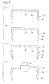
- FIGS. 4A to 4C illustrate process diagrams of a process for the casing body.
- a casing body 30 with the opening 20a is prepared (step S 10).
- the casing body 30 is the casing body 20 without the convex part 24.
- the convex part 24 is formed in the casing body 30 to form the casing body 20 (step S11).
- the convex part 24 is formed by pressing the casing body 30.
- FIG. 4A to 4C illustrate process diagrams of a process for the casing body.
- step S12 the positive electrode sheet 13 having the connection part 13b, the negative electrode sheet 14 having the connection part 14b (not shown) and, the separator 15 are inserted in the casing body 20 (step S12).
- the convex part 24 may not be formed due to a circumstance such as a cost reduction request or a design specification of the secondary battery 1. In this case, step S11 is omitted, and step S12 is progressed.
- FIGS. 5A to 5D illustrate process diagrams of a process for the cover.
- a cover 31 is prepared (step S20).
- the cover 31 has an attachment hole 27 used to attach the positive electrode terminal 11 at the top plate 33 of the cover 31.
- a thin part 28 is formed by pressing the edge of a side wall 34 of the cover 31.
- the thin part 28 with compared to the thickness of the side wall 34 (step S21).
- the thin part 28 is used as a welding part in the welding to be described later.
- the side wall 34 of the cover 31 is a part that covers the external surface 20b of the casing body 20 when the cover 31 is attached to the casing body 20.
- the concave part 25 is formed in the cover 32 to form the cover 21 (step S21).
- the concave part 25 may be formed by the pressing or the like.
- the positive electrode terminal 11 and the negative electrode terminal 12 are attached to the attachment holes 27 of the cover 21 (step S22).
- the corresponding concave part 25 may not be formed.
- the thin part 28 may be also omitted.
- the attachment hole 27 may be formed ahead of step S22 and may be formed in step S21.
- FIGS. 6A and 6B illustrate process diagrams of a process assembling the cover and the casing body.
- the connection part 13b is electrically connected to the positive electrode terminal 11, and the cover 21 is fitted to the outside of the casing body 20 (step S30 and step S31).
- the cover 21 is joined and pushed into the casing body 20 by using a handler in order that the convex part 24 is fitted to the concave part 25. Because the convex part 24 is fitted to the concave part 25, a positional deviation between the cover 21 and the casing body 20 does not easily occur. Subsequently, as shown in FIG.
- the casing body 20 is reversed and held by the handler, while the cover 21 is put on a support table 8. And then the edge of the side wall 34 ( FIG. 5 ) of the cover 21, that is, the thin part 28 or the vicinity of the thin part 28 is welded to the external surface 20b of the casing body 20 (step S32).
- the casing body 20 and the cover 21 are welded by welding machine such as a laser welding equipment 9 while the casing body is placed upside down and the opening is directed downward.
- welding machine such as a laser welding equipment 9
- the support table 8 has a recess part 81 that receives the positive electrode terminal 11 or the negative electrode terminal 12 protruding from the cover 21.
- the laser welding machine 9 includes a laser beam source, an optical system with uniform optical intensity, and is used to emit a laser beam L to a welding portion.
- the position of the welding portion may be highly precisely controlled.
- the battery case is hermetically sealed.
- the air gap between the outer diameter of the casing body 20 and the inner diameter of the cover 21, is buried effectively.
- the fitting part 23 including the convex part 24 and the concave part 25 is formed, because the molten metal is blocked by the fitting part 23, it is possible to sufficiently prevent the molten metal from extending downward from the fitting part 23.
- the secondary battery 1 is obtained (step S33).
- a machine 2 for manufacturing the secondary battery 1 schematically has the following structure.
- the same reference marks will be given to the same components and members, and the description thereof will be appropriately omitted.
- the machine 2 for manufacturing the secondary battery 1 includes at least a cover fitting mechanism 85 that makes the outside-fitting and the casing body 20, a reversing mechanism 82 that reverses the casing body 20 being made the outside-fitting to the cover 21, the support table 8, the laser welding equipment 9, and a controller 83 that controls the reversing mechanism 82 and the laser welding equipment 9.
- the machine may further include a mechanism that forms the convex part 24 or the concave part 25, or a mechanism that injects an electrolyte.
- the cover fitting mechanism 85 and the reversing mechanism 82 are, for example, handlers.
- the cover fitting mechanism 85 has a function of making the outside-fitting while the reversing mechanism 82 holds the casing body 20.
- the reversing mechanism 82 has a function of reversing the casing body 20.
- the reversing mechanism 82 reverses the casing body 20 to put on the support table 8 in order that the positive electrode terminal 11 is received in the recess part 81 formed in the support table 8.
- the laser welding equipment 9 has a function of welding the cover 21 and the casing body 20 by emitting the laser beam L to the thin part 28 on the basis of the control signal of the controller 83. Because the laser welding equipment 9 is movable, it is able to the laser beam L along the thin part 28. Furthermore, the method for the welding is not limited thereto. For example, the laser welding equipment 9 may weld the edge of the cover 21 and the battery case 10 while the laser welding equipment 9 is fixed and the casing body 20 having the cover 21 fitted to the outside thereof is rotated.
- the controlling section 83 includes, for example, a CPU or the like mounted on a PC, and the controlling section 83 transmits control signals to the reversing mechanism 82, the laser welding equipment 9, the driving mechanism 84 to operate them.
- the casing body 20 is reversed in order that the cover 21 is positioned downward after the outside-fitting is executed.
- the laser welding equipment 9 is able to the laser beam L downward and the metal melted at the thin part 28 enters a boundary surface between the external surface 20b of the casing body 20 and the inner surface of the cover 21. Accordingly, as described above, the air-tightness of the battery case is improved by the welding.
- the technical scope of the invention is not limited to the above-described embodiment. Various modifications may be made within the scope not departing from the spirit of the invention. For example, even when the concave part or the convex part is not formed, it is still effective to form the battery case because of the outside-fitting.
- the type of the recessed part or the protruding part is modified in various forms. A part of external surface of the casing body may be convexed toward the inside of the casing body, a part of the inner wall of the cover may be convexed toward the outside of the cover. When the fitting part is protruding toward the inside of the battery case, the unevenness of the outer surface of the battery case may be reduced.
- the fitting part when the fitting part is protruding outward from the inside of the battery case, it is possible to avoid interference between the inner member of inner of the battery case and the fitting part.
- the concave part or the convex part may also be provided only at a part of the battery case in the circumferential direction.
- the casing body may leave both ends that are opened in the axial direction. In this case, the cover may be attached to both openings.
Landscapes
- Chemical & Material Sciences (AREA)
- Chemical Kinetics & Catalysis (AREA)
- Electrochemistry (AREA)
- General Chemical & Material Sciences (AREA)
- Engineering & Computer Science (AREA)
- Manufacturing & Machinery (AREA)
- Sealing Battery Cases Or Jackets (AREA)
- Secondary Cells (AREA)
Abstract
A battery of the invention includes: a machine part (20) having an opening opened from at least one edge thereof and a cover (21) having an outer diameter larger than the diameter of the opening and covering the opening. The cover (21) is fitted to the outside of the casing body (20) by an outside-fitting, and the edge of the cover (21) and the casing body (20) are welded to each other to form a battery case (10). Because the cover(21) is fitted and welded to the outside of the casing body (20), the cover (21) does not fall into the casing body (20), and metal melted during the welding of the cover does not flow into the inside of the casing body (20).
Description
- The present invention relates to a battery, a battery manufacturing machine, and a battery manufacturing method.
Priority is claimed on Japanese Patent Application No.2010-020325, filed on February 1, 2010 - A unit cell or an assembled battery has been used as a power supply of an electronic device or the like. As an example of the assembled battery, recently, a secondary battery such as a lithium ion secondary battery with high energy density has been developed. And the unit cell or the assembled battery has been used as a part of a home electrical storage device or as a power supply of an electric vehicle, because they have high energy density.
- Here, the secondary battery includes a battery case storing an electrolyte, an electrode sheet being soaked in the electrolyte, and an electrode terminal being electrically connected to the electrode sheet. And, the electrode terminal is arranged on the battery case. The battery case includes, for example, the casing body having an opening, and a cover closing the opening. The electrode plate is inserted in the casing body from the opening and the cover is attached to close and to seal the opening hermetically.
- As a method of attaching the cover to the casing body, a technique disclosed in Patent Document 1 may be exemplified. In Patent Document 1, the cover is fitted to the inside of the opening of the casing body. Hereinafter, the method of fitting the cover to the opening as described in Patent Document 1 is defined as "inside-fitting". The cover and the casing body is welded and connected by a laser welding machine, after the edge of the casing body and the cover are leveled by the inside-fitting. In the specification, the inside-fitting indicates a technique to fit the cover into the battery case. Therefore the cover has an outer diameter substantially equal to the diameter of the opening of the casing body.
- [Patent Document 1] Japanese Patent Application Laid-Open No.
2003-181666 - In Patent Document 1, because the cover is inside-fitted to the casing body, there are problems as below.
As a first problem, because the cover fits to the opening by the inside-fitting the cover may fall into the casing body erroneously during the inside-fitting. For preventing the cover from falling into the casing body, for example, the edge of the casing body around the opening may be formed to be thinner at the upper part of the main body than the other parts in order that the cover is held by other parts. According to this method, it is possible to prevent the cover from falling into the casing body, but productivity is may become worse because highly precise cutting is necessary for making the shape of the upper part. - Further, in Patent Document 1, the casing body and the cover are welded each other while the opening is arranged at the upper side of casing body. It is a second Problem that the method, the molten metal by the welding flows into the inside of the casing body and the molten metal contact the inside of the battery case, a defect such as short-circuit may occur.
- The invention is made to solve these problems described above, and it is an object of the invention to provide the battery which is assembled at low cost, and to provide a manufacturing machine of battery.
- A battery comprising: a casing body having an opening opened from at least one edge thereof; and a cover having an outer diameter larger than the diameter of the opening and covering the opening; wherein the cover is fitted to the outside of the casing body by an outside-fitting, and the edge of the cover and the casing body are welded to each other to form a battery case.
- In this manner, because the cover is fitted to the casing body to the casing body by the outside-fitting described later, the cover does not fall into the casing body when the cover is fitted to the casing body. Therefore, compared with the inside-fitting, it is possible to obtain the battery having the cover fitted to the casing body easily. Therefore, the battery may be made at low cost. Further, because the cover is welded to the outer peripheral surface of the casing body, the metal melted during the welding of the cover does not flow into the inside of the casing body. Therefore, the short-circuit is not easily occurred.
- A battery manufacturing machine according to the invention, the battery manufacturing machine includes: a support table on which the battery is placed; a reversing mechanism that holds and reverses the casing body; a welding machine for welding the edge of the cover and the casing body to each other; and a controller that controls the reversing mechanism and the welding machine, wherein the support table is provided with an recess part that receives an electrode terminal of the battery, and the controller controls the reversing mechanism in order that the casing body is reversed and put on the support table for the electrode terminal to received in the recess part, and the controller controls the welding machine in order that the edge of the cover and the casing body are welded to each other by the welding machine.
- A battery manufacturing method of manufacturing the battery according to the invention, the battery manufacturing method comprising: fitting the cover to the outside of the casing body by the outside-fitting; reversing the casing body having the cover fitted to the outside thereof; and welding the edge of the cover and the battery body to each other after the reversing.
- According to the battery manufacturing machine of the invention or the battery manufacturing method of the invention, the cover is fitted to the outside of the casing body, the casing body and the cover is reversed, and the cover and the casing body are welding each other. Therefore, it is possible to prevent the cover from falling in the casing body. And, it is possible to easily and reliably fit the cover to the casing body, and to efficiently and highly-precisely weld the cover to the casing body for sealing the battery tightly. Further, because the metal melted during the welding does not stream into the inside of the casing body, an excellent battery may be manufactured. Further, it is possible to manufacture an excellent battery at low cost.
- In the invention, because the cover is fitted and welded to the outside of the casing body, it is possible to reduce the assembly cost of the battery and prevent molten metal from entering the casing body during the welding. Further, it is possible to manufacture the excellent battery at low cost.
-
-
FIG. 1 illustrates a perspective view of one embodiment of a battery according to the invention. -
FIG. 2A illustrates a cross-sectional view along the line A-A' ofFIG. 1 , andFIG. 2B illustrates a cross-sectional view along the line B-B' ofFIG. 1 . -
FIG. 3 illustrates a flowchart for one embodiment of a battery case manufacturing method. - FIGS. 4A to 4C illustrate process diagrams of a process for a casing body.
- FIGS. 5A to 5D illustrate process diagrams of a process for a cover.
-
FIGS. 6A and 6B illustrate process diagrams of a process of assembling the cover and the casing body. - Hereinafter, an embodiment of the invention is described by referring to the drawings. In the drawings, the dimensions or the scales of the structures of the drawings may be different from those of the real structure in order that characteristic of the invention is easily understood. Further, the same reference marks or numbers will be given to the same components of the embodiments, and a parts of the same marks may not be described again.
-
FIG. 1 illustrates a perspective view of a schematic configuration of a secondary battery 1 as one embodiment of the invention,FIG. 2A illustrates a cross-sectional view taken along the line A-A' ofFIG. 1 , andFIG. 2B illustrates a cross-sectional view taken along the line B-B' ofFIG. 1 . The secondary battery 1 of the embodiment is a lithium ion secondary battery which is a stacked type, but the application scope of the invention is not limited to the lithium ion secondary battery. The invention may be applied to a battery such as a wound lithium ion secondary battery which is a wound type, a secondary battery other than the lithium ion secondary battery, or a primary battery. - As shown in
FIG. 1 , the secondary battery 1 includes abattery case 10, and the electrode terminals (i.e., apositive electrode terminal 11 and a negative electrode terminal 12). Thebattery case 10 includes acasing body 20 of which one end is opened and acover 21 which closes the opening of thecasing body 20. Furthermore, thebattery case 10 is a metallic case made of aluminum in a substantially rectangular parallelepiped shape. The outer shape of thebattery case 10 may be a shape other than the substantially rectangular column shape (e.g., a substantially cylindrical shape). - The
casing body 20 has a shape which has a wall surface surrounding the periphery of an axis in an annular shape (e.g., a cylindrical shape or a rectangular column shape). The outline of thecasing body 20 perpendicular to the axis passing through the opening is any one of a closed curve such as a circle and an oval, a polygon, a shape obtained by making the corner of the polygon round, a shape (e.g., an ellipse) obtained by the combination thereof. Further, the outline of the inside of thecasing body 20 perpendicular to the axis may be line like a circle or like a polygon. - The
positive electrode terminal 11 and thenegative electrode terminal 12 are arranged at a surface of thebattery case 10. Thepositive electrode terminal 11 and thenegative electrode terminal 12 are formed in a column shape (e.g., a cylindrical shape), and protrudes in the direction perpendicular to the surface where the terminal is arranged. Thepositive electrode terminal 11 is electrically connected to thebattery case 10 through un-illustrated connection part (e.g., it has a highly resistance). The potential of thebattery case 10 is controlled in order that it is substantially equal to that of, for example, thepositive electrode terminal 11. So the reaction between thebattery case 10 and lithium ions is prevented. - Hereinafter, a positional relation of components will be described on the basis of the XYZ orthogonal coordinate system shown in
FIG. 1 .
In the XYZ orthogonal coordinate system, the X direction and the Y direction are a direction along the surface where the electrode terminal is arranged, and the Z direction is a direction along a normal like which is perpendicular to the surface. Here, the direction for arranging thepositive electrode terminal 11 and thenegative electrode terminal 12 is the X direction. Thenegative electrode terminal 12 is arranged to the +X direction from thepositive electrode terminal 11. - As shown in
FIGS. 2A and 2B , thecasing body 20 is a substantially rectangular-column-shaped hollow case with anopening 20a. Thecover 21 is fitted to the outside of thecasing body 20 to close and cover theopening 20a. Hereinafter, this method for fitting the cover is defined as the "outside-fitting"). Furthermore, in the embodiment, thecover 21 is weld for fitting to thecasing body 20 to theexternal surface 20b at awelding portion 26 of thecover 21. Furthermore, thecover 21 has a through-hole, and thepositive electrode terminal 11 and thenegative electrode terminal 12 are arranged at the through-hole with an insulating member. Furthermore, as shown inFIG. 1 , thecover 21 hasinjection port 22 for injecting electrolyte above theopening 20a. - In the embodiment, the
cover 21 hasconvex part 24 at the outside of thecasing body 20. Here, theconvex part 24 is formed around theexternal surface 20b where is the periphery of thecasing body 20 about the Z-axis. Aconcave part 25 corresponding to the shape of theconvex part 24 is formed around the internal surface of thecover 21. Theconvex part 24 and theconcave part 25 are formed by pressing working and those are fitted to each other. Furthermore, as described below, theconvex part 24 or theconcave part 25 may not be necessarily formed all around the external surface of the casing body or the internal surface of the cover. For example, theconvex part 24 or theconcave part 25 may be intermittently formed. -
Positive electrode sheets 13 andnegative electrode sheets 14 are repeatedly arranged in the Y direction. Thepositive electrode sheet 13 is arranged to thenegative electrode sheet 14 face-to-face. Aseparator 15 is inserted between thepositive electrode sheet 13 and thenegative electrode sheet 14. Thepositive electrode sheet 13 does not contact thenegative electrode sheet 14 are formed of a conductive foil or a conductive thin sheet. - The
positive electrode sheet 13 has apositive electrode tab 13a. Thepositive electrode tab 13a is electrically connected to aconnection part 13b, and theconnection part 13b is electrically connected to thepositive electrode terminal 11. Thepositive electrode tabs 13a of the plurality ofpositive electrode sheets 13 are gathered and electrically connected to thepositive electrode terminal 11. - The
negative electrode sheet 14 has anegative electrode tab 14a. Thenegative electrode tab 14a is electrically connected to aconnection part 14b, and theconnection part 14b is electrically connected to thenegative electrode terminal 12. Thenegative electrode tabs 14a of the plurality ofnegative electrode sheets 14 are gathered and electrically connected to thenegative electrode terminal 12. - The
battery case 10 stores electrolyte containing lithium ion, that is an electrolytic solution containing lithium ion or a solid material containing lithium ion. Thebattery case 10 is insulated from the electrode sheets by coating the inner surface of thebattery case 10, for example, with an insulating film. - According to the
battery case 10, Because thecover 21 is fitted to the outside of thecasing body 20, thecover 21 does not fall into thecasing body 20 and thebattery case 10 is easily assembled with compared to the inside-fitting. - Because, the
concave part 25 of thecover 21 is fitted to theconvex part 24 of thecasing body 20, it is possible to assemble and weld them easily. Furthermore, even when molten metal flows into thecasing body 20, the molten metal stays at thefitting part 23. Theconvex part 24 and theconcave part 25 are fitted each other at thefitting part 23. In particular, because theconvex part 24 and theconcave part 25 are formed throughout theexternal surface 20b in the circumferential direction, it is possible to reliably prevent the molten metal from flowing into thecasing body 20. - Because the
battery case 10 is easily assembled, manufacturing costs are reduced. Further, molten metal generated by the welding does not flow into thecasing body 20, it is possible to prevent the short-circuit. Thus, the secondary battery 1 according to the invention is made at low cost, and the battery characteristics are satisfactory. - Next, one embodiment of a secondary battery manufacturing method according to the invention will be described.
FIG. 3 illustrates a flowchart of one embodiment of the secondary battery manufacturing method. As shown inFIG. 3 , the method of manufacturing the secondary battery 1 schematically includes the following steps. Furthermore, in the description below, a case in which a manufacturing process is an automated line will be described, but the invention is not limited thereto, and one or more steps or a part of each step may be manually performed. - First, in
step S 10, a casing body is prepared for manufacturing the secondary battery. Specifically, the casing body is prepared and conveyed to the next step by using a conveying device (e.g. a belt conveyor). In step S11, the casing body is processed to form a convex part. In step S12, electrode sheets are stored into the casing body. Further, in step S20, a cover is prepared and the step S20 is started together with step S10. Specifically, the cover is prepared and conveyed to the next step by using a conveying device such as a belt conveyor. In step S21, the cover is pressed to form concave part. In step S22, an electrode terminal is attached to the cover. Specifically, the cover and the electrode terminal are bonded to each other by a resin. Afterstep S 12 and step S22 are completed, in step S30, the electrode sheet and the electrode terminal are electrically connected to each other. In step S31, the cover is fitted to the outside of the casing body by outside-fitting. In step S32, the battery case is manufactured by welding the casing body and the cover to each other. In step S33, an electrolyte is injected into the battery case to form a secondary battery. - Hereinafter, each step of the method of manufacturing the secondary battery 1 will be specifically described.
FIGS. 4A to 4C illustrate process diagrams of a process for the casing body.
As shown inFIG. 4A , acasing body 30 with theopening 20a is prepared (step S 10). Thecasing body 30 is thecasing body 20 without theconvex part 24. Subsequently, as shown inFIG. 4B , theconvex part 24 is formed in thecasing body 30 to form the casing body 20 (step S11). Theconvex part 24 is formed by pressing thecasing body 30. Subsequently, as shown inFIG. 4C , thepositive electrode sheet 13 having theconnection part 13b, thenegative electrode sheet 14 having theconnection part 14b (not shown) and, theseparator 15 are inserted in the casing body 20 (step S12).
Furthermore, for example, theconvex part 24 may not be formed due to a circumstance such as a cost reduction request or a design specification of the secondary battery 1. In this case, step S11 is omitted, and step S12 is progressed. - FIGS. 5A to 5D illustrate process diagrams of a process for the cover.
As shown inFIG. 5A , acover 31 is prepared (step S20). Here, thecover 31 has anattachment hole 27 used to attach thepositive electrode terminal 11 at thetop plate 33 of thecover 31. Subsequently, as shown inFIG. 5B , athin part 28 is formed by pressing the edge of aside wall 34 of thecover 31. Thethin part 28 with compared to the thickness of the side wall 34 (step S21). Thethin part 28 is used as a welding part in the welding to be described later. Theside wall 34 of thecover 31 is a part that covers theexternal surface 20b of thecasing body 20 when thecover 31 is attached to thecasing body 20. Subsequently, as shown inFIG. 5C , theconcave part 25 is formed in thecover 32 to form the cover 21 (step S21). Theconcave part 25 may be formed by the pressing or the like. Subsequently, as shown inFIG. 5D , thepositive electrode terminal 11 and the negative electrode terminal 12 (not shown) are attached to the attachment holes 27 of the cover 21 (step S22). - Further, as described above, when the casing body is not formed with the convex part, the corresponding
concave part 25 may not be formed. Thethin part 28 may be also omitted. Theattachment hole 27 may be formed ahead of step S22 and may be formed in step S21. -
FIGS. 6A and 6B illustrate process diagrams of a process assembling the cover and the casing body.
In order to assemble thecover 21 and thecasing body 20, as shown inFIG. 6A , theconnection part 13b is electrically connected to thepositive electrode terminal 11, and thecover 21 is fitted to the outside of the casing body 20 (step S30 and step S31). Here, thecover 21 is joined and pushed into thecasing body 20 by using a handler in order that theconvex part 24 is fitted to theconcave part 25. Because theconvex part 24 is fitted to theconcave part 25, a positional deviation between thecover 21 and thecasing body 20 does not easily occur. Subsequently, as shown inFIG. 6B , thecasing body 20 is reversed and held by the handler, while thecover 21 is put on a support table 8. And then the edge of the side wall 34 (FIG. 5 ) of thecover 21, that is, thethin part 28 or the vicinity of thethin part 28 is welded to theexternal surface 20b of the casing body 20 (step S32). - In the embodiment, the
casing body 20 and thecover 21 are welded by welding machine such as alaser welding equipment 9 while the casing body is placed upside down and the opening is directed downward. Hereinafter, the operation of directing thecover 21 attached to thecasing body 20 downward is referred to as the "reversing". The support table 8 has arecess part 81 that receives thepositive electrode terminal 11 or thenegative electrode terminal 12 protruding from thecover 21. Thelaser welding machine 9 includes a laser beam source, an optical system with uniform optical intensity, and is used to emit a laser beam L to a welding portion. - Accordingly, in the method of manufacturing the secondary battery 1 of the embodiment, because of the reversing, it is possible to see the inner surface of the
cover 21 and theexternal surface 20b of thecasing body 20 from the upside when they are welded. In other words, a degree of freedom of the direction in which the laser beam L is emitted increases, and a bad influence or the like of the laser beam L reflected from the welding portion may be easily prevented. Further, the position of the welding portion may be highly precisely controlled. - Further, it is possible to prevent molten metal from flowing into the
casing body 20, when welding thecover 21 and thecasing body 20 to each other. The molten metal enters a boundary surface between the inner surface of thecover 21 and theexternal surface 20b of thecasing body 20. Accordingly, the battery case is hermetically sealed. In other words, the air gap between the outer diameter of thecasing body 20 and the inner diameter of thecover 21, is buried effectively. In the case that thefitting part 23 including theconvex part 24 and theconcave part 25 is formed, because the molten metal is blocked by thefitting part 23, it is possible to sufficiently prevent the molten metal from extending downward from thefitting part 23. - Accordingly after the
cover 21 is welded to thecasing body 20 and the electrolyte is injected into thebattery case 10 through theelectrolyte injection port 22, the secondary battery 1 is obtained (step S33). - As shown in
FIG. 6 , amachine 2 for manufacturing the secondary battery 1 schematically has the following structure. In the description below, the same reference marks will be given to the same components and members, and the description thereof will be appropriately omitted. - The
machine 2 for manufacturing the secondary battery 1 includes at least a coverfitting mechanism 85 that makes the outside-fitting and thecasing body 20, a reversingmechanism 82 that reverses thecasing body 20 being made the outside-fitting to thecover 21, the support table 8, thelaser welding equipment 9, and acontroller 83 that controls the reversingmechanism 82 and thelaser welding equipment 9.
If necessary, the machine may further include a mechanism that forms theconvex part 24 or theconcave part 25, or a mechanism that injects an electrolyte. - The cover
fitting mechanism 85 and the reversingmechanism 82 are, for example, handlers. The coverfitting mechanism 85 has a function of making the outside-fitting while the reversingmechanism 82 holds thecasing body 20. During the outside-fitting thecasing body 20 is held by the reversingmechanism 82 while thecasing body 20 is put on a working table. The reversingmechanism 82 has a function of reversing thecasing body 20. On the basis of the control signal from thecontroller 83, the reversingmechanism 82 reverses thecasing body 20 to put on the support table 8 in order that thepositive electrode terminal 11 is received in therecess part 81 formed in the support table 8. - The
laser welding equipment 9 has a function of welding thecover 21 and thecasing body 20 by emitting the laser beam L to thethin part 28 on the basis of the control signal of thecontroller 83. Because thelaser welding equipment 9 is movable, it is able to the laser beam L along thethin part 28. Furthermore, the method for the welding is not limited thereto. For example, thelaser welding equipment 9 may weld the edge of thecover 21 and thebattery case 10 while thelaser welding equipment 9 is fixed and thecasing body 20 having thecover 21 fitted to the outside thereof is rotated. - The controlling
section 83 includes, for example, a CPU or the like mounted on a PC, and the controllingsection 83 transmits control signals to the reversingmechanism 82, thelaser welding equipment 9, thedriving mechanism 84 to operate them. - By the
manufacturing machine 2 thecasing body 20 is reversed in order that thecover 21 is positioned downward after the outside-fitting is executed. And thelaser welding equipment 9 is able to the laser beam L downward and the metal melted at thethin part 28 enters a boundary surface between theexternal surface 20b of thecasing body 20 and the inner surface of thecover 21. Accordingly, as described above, the air-tightness of the battery case is improved by the welding. - Furthermore, the technical scope of the invention is not limited to the above-described embodiment. Various modifications may be made within the scope not departing from the spirit of the invention. For example, even when the concave part or the convex part is not formed, it is still effective to form the battery case because of the outside-fitting.
The type of the recessed part or the protruding part is modified in various forms. A part of external surface of the casing body may be convexed toward the inside of the casing body, a part of the inner wall of the cover may be convexed toward the outside of the cover. When the fitting part is protruding toward the inside of the battery case, the unevenness of the outer surface of the battery case may be reduced. Further, when the fitting part is protruding outward from the inside of the battery case, it is possible to avoid interference between the inner member of inner of the battery case and the fitting part. Further, the concave part or the convex part may also be provided only at a part of the battery case in the circumferential direction.
The casing body may leave both ends that are opened in the axial direction. In this case, the cover may be attached to both openings. -
- 1:
- SECONDARY BATTERY (BATTERY)
- 2:
- SECONDARY BATTERY MANUFACTURING MACHINE
- 8:
- SUPPORT TABLE
- 9:
- LASER WELDING EQUIPMENT
- 10:
- BATTERY CASE
- 11:
- POSITIVE ELECTRODE TERMINAL (ELECTRODE TERMINAL)
- 12:
- NEGATIVE ELECTRODE TERMINAL (ELECTRODE TERMINAL)
- 13:
- POSITIVE ELECTRODE SHEET
- 13a:
- POSITIVE ELECTRODE TAB
- 13b:
- CONNECTION PART
- 14:
- NEGATIVE ELECTRODE SHEET
- 14a:
- NEGATIVE ELECTRODE TAB
- 14b:
- CONNECTION PART
- 15:
- SEPARATOR
- 20:
- CASING BODY
- 20a:
- OPENING
- 20b:
- EXTERNAL SURFACE
- 21:
- COVER
- 22:
- ELECTROLYTE INJECTION PORT
- 23:
- FITTING PART
- 24:
- PROTRUDING PART
- 25:
- RECESSED PART
- 26:
- WELDING PART
- 27:
- ATTACHMENT HOLE
- 28:
- THIN PART
- 30:
- CASING BODY
- 31, 32:
- COVER
- 33:
- TOPPLATE
- 34:
- SIDE WALL
- 81:
- RECESS PART
- 82:
- REVERSING MECHANISM
- 83:
- CONTROLLER
- 84:
- DRIVING MECHANISM
- 85:
- COVER FITTING MECHANISM
- L:
- LASER BEAM
- S10 TO S12, S20 TO S22, S30 TO S33:
- STEP
Claims (5)
- A battery comprising:a casing body having an opening opened from at least one edge thereof; anda cover having an outer diameter larger than the diameter of the opening and covering the opening;wherein the cover is fitted to the outside of the casing body by an outside-fitting, and the edge of the cover and the casing body are welded to each other to form a battery case.
- The battery according to claim 1,
wherein the cover has a thin part at the edge, and
the thin part is welded to the main part. - The battery according to claim 2,
wherein the casing body has a convex part toward the outside of the case, the cover has a concave part corresponding to the shape of the convex part, and the convex part is fitted to the concave part each other for the outside-fitting. - A battery manufacturing machine for manufacturing the battery according to any one of claims 1 to 3, the battery manufacturing machine comprising:a support table on which the battery is placed;a reversing mechanism that holds and reverses the casing body;a welding machine for welding the edge of the cover and the casing body to each other; anda controller that controls the reversing mechanism and the welding machine,wherein the support table is provided with an recess part that receives an electrode terminal of the battery, andthe controller controls the reversing mechanism in order that the casing body is reversed and put on the support table for the electrode terminal to received in the recess part, and the controller controls the welding machine in order that the edge of the cover and the casing body are welded to each other by the welding machine.
- A battery manufacturing method of manufacturing the battery according to any one of claims 1 to 3, the battery manufacturing method comprising:fitting the cover to the outside of the casing body by the outside-fitting;reversing the casing body having the cover fitted to the outside thereof; andwelding the edge of the cover and the battery body to each other after the reversing.
Applications Claiming Priority (2)
| Application Number | Priority Date | Filing Date | Title |
|---|---|---|---|
| JP2010020325A JP2011159498A (en) | 2010-02-01 | 2010-02-01 | Battery, and apparatus and method for manufacturing the same |
| PCT/JP2011/051995 WO2011093503A1 (en) | 2010-02-01 | 2011-02-01 | Battery, battery production device, and battery production method |
Publications (1)
| Publication Number | Publication Date |
|---|---|
| EP2533323A1 true EP2533323A1 (en) | 2012-12-12 |
Family
ID=44319480
Family Applications (1)
| Application Number | Title | Priority Date | Filing Date |
|---|---|---|---|
| EP11737212A Withdrawn EP2533323A1 (en) | 2010-02-01 | 2011-02-01 | Battery, battery production device, and battery production method |
Country Status (7)
| Country | Link |
|---|---|
| US (1) | US20130071727A1 (en) |
| EP (1) | EP2533323A1 (en) |
| JP (1) | JP2011159498A (en) |
| KR (1) | KR20120112656A (en) |
| CN (1) | CN203250793U (en) |
| TW (1) | TW201212338A (en) |
| WO (1) | WO2011093503A1 (en) |
Families Citing this family (15)
| Publication number | Priority date | Publication date | Assignee | Title |
|---|---|---|---|---|
| JP5861524B2 (en) * | 2012-03-23 | 2016-02-16 | 株式会社豊田自動織機 | Power storage module |
| JP6155964B2 (en) * | 2013-08-22 | 2017-07-05 | 株式会社豊田自動織機 | Case for power storage device and power storage device |
| CN110268545B (en) | 2017-03-31 | 2022-05-17 | 松下知识产权经营株式会社 | Battery with a battery cell |
| JP7110192B2 (en) * | 2017-06-28 | 2022-08-01 | 三洋電機株式会社 | Battery and its manufacturing method |
| JP6994160B2 (en) * | 2018-04-16 | 2022-02-04 | トヨタ自動車株式会社 | Battery manufacturing method and battery manufacturing system |
| JP7340818B2 (en) * | 2018-11-30 | 2023-09-08 | パナソニックIpマネジメント株式会社 | battery |
| KR102914059B1 (en) * | 2020-10-12 | 2026-01-16 | 주식회사 엘지에너지솔루션 | Button type secondary battery |
| KR102800399B1 (en) | 2021-09-28 | 2025-04-25 | 컨템포러리 엠퍼렉스 테크놀로지 (홍콩) 리미티드 | Battery cells, cover assemblies, batteries, electrical devices, methods and devices |
| EP4672449A3 (en) * | 2021-09-30 | 2026-04-01 | Contemporary Amperex Technology (Hong Kong) Limited | Battery cell, method and system for manufacturing same, battery, and electrical device |
| JP7694803B2 (en) * | 2022-03-14 | 2025-06-18 | 株式会社村田製作所 | Secondary battery, battery pack, electronic device, power tool, electric aircraft, and electric vehicle |
| CN115377568B (en) * | 2022-07-13 | 2023-06-30 | 江西微电新能源有限公司 | Button cell and preparation method thereof |
| SE546550C2 (en) * | 2022-08-31 | 2024-11-26 | Northvolt Ab | A cylindrical secondary cell comprising a reduced radius enclosure and a lid |
| US12355095B2 (en) * | 2022-12-08 | 2025-07-08 | Ford Global Technologies, Llc | Battery enclosure and method of manufacturing a battery enclosure |
| JP7731865B2 (en) * | 2022-12-28 | 2025-09-01 | プライムプラネットエナジー&ソリューションズ株式会社 | Electricity storage device manufacturing method and electricity storage device |
| KR20250177766A (en) * | 2024-06-17 | 2025-12-24 | 삼성에스디아이 주식회사 | Battery and method of manufacturing same |
Family Cites Families (17)
| Publication number | Priority date | Publication date | Assignee | Title |
|---|---|---|---|---|
| US1520495A (en) * | 1923-03-19 | 1924-12-23 | Cleveland Engineering Lab Comp | Storage-cell cover |
| US3736190A (en) * | 1972-03-02 | 1973-05-29 | Mallory & Co Inc P R | Hermetically sealed structures for organic electrolyte systems |
| JPS61154784A (en) * | 1984-12-27 | 1986-07-14 | Fujitsu Ltd | Laser welding device |
| JP2993238B2 (en) * | 1991-11-22 | 1999-12-20 | 富士電気化学株式会社 | Manufacturing method of cylindrical alkaline battery |
| JPH06310168A (en) * | 1993-04-21 | 1994-11-04 | Matsushita Electric Ind Co Ltd | Manufacturing method of sealed lead-acid battery |
| US5879416A (en) * | 1995-03-13 | 1999-03-09 | Nippondenso Co., Ltd. | Method of manufacturing battery having polygonal case |
| JP4088360B2 (en) * | 1997-10-20 | 2008-05-21 | 松下電器産業株式会社 | Collective sealed secondary battery |
| JP3051814U (en) * | 1998-02-25 | 1998-09-02 | 関西製缶株式会社 | Metal container |
| JP2000090893A (en) * | 1998-09-17 | 2000-03-31 | Japan Storage Battery Co Ltd | Battery and method for manufacturing battery |
| JP2001338624A (en) * | 2000-03-21 | 2001-12-07 | Ngk Insulators Ltd | Anode container for sodium-sulfur cell |
| JP2002289155A (en) * | 2001-03-23 | 2002-10-04 | Mitsubishi Heavy Ind Ltd | Secondary battery and method of manufacturing the same |
| JP2003157901A (en) * | 2001-11-20 | 2003-05-30 | Gs-Melcotec Co Ltd | Secondary cell |
| JP2003181666A (en) | 2001-12-11 | 2003-07-02 | Mitsubishi Heavy Ind Ltd | Method for welding prismatic battery container and method for manufacturing prismatic battery |
| JP4454928B2 (en) * | 2002-11-13 | 2010-04-21 | パナソニック株式会社 | Method for manufacturing prismatic battery |
| US7875088B2 (en) * | 2006-02-03 | 2011-01-25 | EaglePicher Technologies | Automated tracking and storage system for use with an automated thermal battery manufacturing system |
| US20100009276A1 (en) | 2008-07-14 | 2010-01-14 | Kabushiki Kaisha Toshiba | Developing agent and method for producing the same |
| JP2010105041A (en) * | 2008-09-30 | 2010-05-13 | Sanyo Electric Co Ltd | Laser welding jig, laser welding device and method for manufacturing prismatic battery |
-
2010
- 2010-02-01 JP JP2010020325A patent/JP2011159498A/en active Pending
-
2011
- 2011-02-01 CN CN2011900003118U patent/CN203250793U/en not_active Expired - Fee Related
- 2011-02-01 TW TW100103956A patent/TW201212338A/en unknown
- 2011-02-01 EP EP11737212A patent/EP2533323A1/en not_active Withdrawn
- 2011-02-01 US US13/576,043 patent/US20130071727A1/en not_active Abandoned
- 2011-02-01 WO PCT/JP2011/051995 patent/WO2011093503A1/en not_active Ceased
- 2011-02-01 KR KR1020127019729A patent/KR20120112656A/en not_active Ceased
Non-Patent Citations (1)
| Title |
|---|
| See references of WO2011093503A1 * |
Also Published As
| Publication number | Publication date |
|---|---|
| KR20120112656A (en) | 2012-10-11 |
| US20130071727A1 (en) | 2013-03-21 |
| TW201212338A (en) | 2012-03-16 |
| CN203250793U (en) | 2013-10-23 |
| JP2011159498A (en) | 2011-08-18 |
| WO2011093503A1 (en) | 2011-08-04 |
Similar Documents
| Publication | Publication Date | Title |
|---|---|---|
| US20130071727A1 (en) | Battery, battery manufacturing machine, and battery manufacturing method | |
| KR102517901B1 (en) | Rechargeable battery | |
| CN103378318B (en) | The manufacture method of device box and device box | |
| KR102704695B1 (en) | Secondary Battery | |
| KR102618121B1 (en) | Secondary Battery | |
| US9373825B2 (en) | Cell and method for manufacturing cell | |
| KR101693288B1 (en) | Rechargeable battery with fuse | |
| EP3062362B1 (en) | Recharcheable battery and module thereof | |
| US10355250B2 (en) | Lithium cell | |
| US11316223B2 (en) | Cylindrical battery | |
| KR102271383B1 (en) | Cell module and its manufacturing method | |
| CN102683760A (en) | Secondary battery | |
| JP2020205269A (en) | Wound battery | |
| US9350010B2 (en) | Secondary battery and method for fabricating the same | |
| US20130344378A1 (en) | Assembled battery and cell connection method | |
| KR101836339B1 (en) | Closed type battery | |
| CN109713353A (en) | Secondary cell, secondary cell assembly method and battery modules | |
| KR20250103584A (en) | Cylindrical secondary battery cell, and battery pack and vehicle including the same | |
| KR102819179B1 (en) | Secondary battery | |
| KR20160103453A (en) | Rechargeable battery and module of the same | |
| KR20150027114A (en) | Battery and fabrication method thereof | |
| KR20160109656A (en) | Rechargeable battery | |
| US11757153B2 (en) | Cylindrical battery | |
| US10651455B2 (en) | Rechargeable battery | |
| JP6341054B2 (en) | Storage element manufacturing method and storage element |
Legal Events
| Date | Code | Title | Description |
|---|---|---|---|
| PUAI | Public reference made under article 153(3) epc to a published international application that has entered the european phase |
Free format text: ORIGINAL CODE: 0009012 |
|
| 17P | Request for examination filed |
Effective date: 20120723 |
|
| AK | Designated contracting states |
Kind code of ref document: A1 Designated state(s): AL AT BE BG CH CY CZ DE DK EE ES FI FR GB GR HR HU IE IS IT LI LT LU LV MC MK MT NL NO PL PT RO RS SE SI SK SM TR |
|
| DAX | Request for extension of the european patent (deleted) | ||
| STAA | Information on the status of an ep patent application or granted ep patent |
Free format text: STATUS: THE APPLICATION HAS BEEN WITHDRAWN |
|
| 18W | Application withdrawn |
Effective date: 20131002 |