EP2532949A2 - Beleuchtungs- und/oder Signalisierungsvorrichtung mit integriertem Wärmeableiter - Google Patents
Beleuchtungs- und/oder Signalisierungsvorrichtung mit integriertem Wärmeableiter Download PDFInfo
- Publication number
- EP2532949A2 EP2532949A2 EP12170716A EP12170716A EP2532949A2 EP 2532949 A2 EP2532949 A2 EP 2532949A2 EP 12170716 A EP12170716 A EP 12170716A EP 12170716 A EP12170716 A EP 12170716A EP 2532949 A2 EP2532949 A2 EP 2532949A2
- Authority
- EP
- European Patent Office
- Prior art keywords
- dissipator
- radiator
- enclosure
- fins
- series
- Prior art date
- Legal status (The legal status is an assumption and is not a legal conclusion. Google has not performed a legal analysis and makes no representation as to the accuracy of the status listed.)
- Granted
Links
Images

Classifications
-
- F—MECHANICAL ENGINEERING; LIGHTING; HEATING; WEAPONS; BLASTING
- F21—LIGHTING
- F21S—NON-PORTABLE LIGHTING DEVICES; SYSTEMS THEREOF; VEHICLE LIGHTING DEVICES SPECIALLY ADAPTED FOR VEHICLE EXTERIORS
- F21S41/00—Illuminating devices specially adapted for vehicle exteriors, e.g. headlamps
- F21S41/10—Illuminating devices specially adapted for vehicle exteriors, e.g. headlamps characterised by the light source
- F21S41/14—Illuminating devices specially adapted for vehicle exteriors, e.g. headlamps characterised by the light source characterised by the type of light source
- F21S41/141—Light emitting diodes [LED]
-
- F—MECHANICAL ENGINEERING; LIGHTING; HEATING; WEAPONS; BLASTING
- F21—LIGHTING
- F21S—NON-PORTABLE LIGHTING DEVICES; SYSTEMS THEREOF; VEHICLE LIGHTING DEVICES SPECIALLY ADAPTED FOR VEHICLE EXTERIORS
- F21S43/00—Signalling devices specially adapted for vehicle exteriors, e.g. brake lamps, direction indicator lights or reversing lights
- F21S43/10—Signalling devices specially adapted for vehicle exteriors, e.g. brake lamps, direction indicator lights or reversing lights characterised by the light source
- F21S43/13—Signalling devices specially adapted for vehicle exteriors, e.g. brake lamps, direction indicator lights or reversing lights characterised by the light source characterised by the type of light source
- F21S43/14—Light emitting diodes [LED]
-
- F—MECHANICAL ENGINEERING; LIGHTING; HEATING; WEAPONS; BLASTING
- F21—LIGHTING
- F21S—NON-PORTABLE LIGHTING DEVICES; SYSTEMS THEREOF; VEHICLE LIGHTING DEVICES SPECIALLY ADAPTED FOR VEHICLE EXTERIORS
- F21S45/00—Arrangements within vehicle lighting devices specially adapted for vehicle exteriors, for purposes other than emission or distribution of light
- F21S45/40—Cooling of lighting devices
- F21S45/47—Passive cooling, e.g. using fins, thermal conductive elements or openings
-
- F—MECHANICAL ENGINEERING; LIGHTING; HEATING; WEAPONS; BLASTING
- F21—LIGHTING
- F21S—NON-PORTABLE LIGHTING DEVICES; SYSTEMS THEREOF; VEHICLE LIGHTING DEVICES SPECIALLY ADAPTED FOR VEHICLE EXTERIORS
- F21S45/00—Arrangements within vehicle lighting devices specially adapted for vehicle exteriors, for purposes other than emission or distribution of light
- F21S45/40—Cooling of lighting devices
- F21S45/47—Passive cooling, e.g. using fins, thermal conductive elements or openings
- F21S45/48—Passive cooling, e.g. using fins, thermal conductive elements or openings with means for conducting heat from the inside to the outside of the lighting devices, e.g. with fins on the outer surface of the lighting device
-
- F—MECHANICAL ENGINEERING; LIGHTING; HEATING; WEAPONS; BLASTING
- F21—LIGHTING
- F21S—NON-PORTABLE LIGHTING DEVICES; SYSTEMS THEREOF; VEHICLE LIGHTING DEVICES SPECIALLY ADAPTED FOR VEHICLE EXTERIORS
- F21S45/00—Arrangements within vehicle lighting devices specially adapted for vehicle exteriors, for purposes other than emission or distribution of light
- F21S45/40—Cooling of lighting devices
- F21S45/49—Attachment of the cooling means
-
- F—MECHANICAL ENGINEERING; LIGHTING; HEATING; WEAPONS; BLASTING
- F21—LIGHTING
- F21S—NON-PORTABLE LIGHTING DEVICES; SYSTEMS THEREOF; VEHICLE LIGHTING DEVICES SPECIALLY ADAPTED FOR VEHICLE EXTERIORS
- F21S45/00—Arrangements within vehicle lighting devices specially adapted for vehicle exteriors, for purposes other than emission or distribution of light
- F21S45/60—Heating of lighting devices, e.g. for demisting
Definitions
- the present invention relates to a lighting and / or vehicle signaling device and more particularly to the elements whose mission is to dissipate heat from a light source that includes the device.
- the lighting and / or vehicle signaling devices consist mainly of a light source, a housing and a transparent element through which the light from the light source is projected, the transparent element delimiting with the housing an enclosure.
- LEDs For luminance and style issues, one or more light-emitting diodes, called LEDs, should be used. To ensure sufficient luminance on the road, the power dissipated by the LEDs is of the order of 10 Watt.
- Heat is thus released from the light source and if it is not dissipated, it can cause deformation of the housing or the transparent element or cause a lowering of the quality of a luminous flux emitted by the LEDs.
- the object of the present invention is therefore to solve the disadvantages described above mainly by proposing a technical solution to optimize and improve the efficiency of cooling in natural convection and reduce the weight of radiators embedded on the lighting devices and / or signaling devices equipped with such a solution.
- the invention proposes for this purpose a lighting and / or signaling device comprising a housing, a transparent element delimiting with the housing an enclosure, a light source and at least one radiator in thermal contact with said source.
- the radiator extends in the enclosure and the device comprises at least one heat sink, called the first dissipator, which carries out a heat exchange between an air contained in the enclosure and a flow of air outside the chamber. 'pregnant.
- the first dissipator thus represents a cold surface cooled by the outside air flow and which allows the air inside the enclosure to cool.
- the air inside the chamber thus flows from the radiator to the first dissipator before returning to the radiator, by performing a circulation loop, thus creating a natural convection phenomenon inside the enclosure promoting the cooling of the air inside the enclosure.
- the radiator and the first dissipator are distinct.
- the first dissipator comprises a first series of fins, a second series of fins and a base interposed between the first series and the second series, said base being secured to the housing while the first series fins extends in a surrounding volume where the flow of outside air flows, the second set of fins extends in a volume defined by the enclosure, said internal volume.
- the fins of the first dissipator are thermally connected to the base and optimize the heat exchange between the hot air present inside the housing and the cold air present outside the housing.
- the radiator has a portion for capturing a heat released by said source and an advanced dispersion portion of said heat. It is understood by “advanced” that said dispersion portion is located in the internal volume at a distance from the transparent member of between 5 mm and 50 mm. In this way, the radiator brings a maximum of heat near the ice to, in particular, limit condensation on ice. This also improves the heat dissipation at the dispersion portion because it is located near the transparent element, the outer face of the latter being directly in contact with the outside air flow.
- the first dissipator is located above the radiator. In this way, an air flow inside the chamber will be created, the hot air near the radiator going up to the cold source that represents the first heat sink, and then down once cooled to the radiator and making a loop of circulation.
- the first dissipator is located in the extension of the radiator.
- at least one axis perpendicular to a side wall of the housing on which the first dissipator is located cuts at the same time the radiator and the first dissipator.
- at least one axis parallel to the transparent element intersects both the radiator and the first dissipator. This ensures that the heat generated by the radiator rises and is immediately in contact with the first dissipator. In this way, a temperature gradient is created close to the ice between the hot surface (radiator) and the cold surface (first dissipator) so that the speed of the air flow circulating inside the enclosure is accelerated. thus improving natural convection and defogging of ice.
- said device comprises a first conduit disposed above the enclosure and adapted to guide the flow of outside air to the first dissipator, the first conduit comprising a first means of evacuation allowing the flow of outside air out of the first duct.
- the first means of evacuation is, in particular, a grid and thus allows the flow of outside air to renew itself and to remain at a temperature allowing the cooling of the first dissipator.
- said device comprises a second heat sink located below the radiator and which carries out an exchange between the air in the enclosure and the outside air flow.
- the second device is distinct from the radiator and the first dissipator. The presence of the second heat sink, in addition to the first heat sink, can thus increase the cooling capacity of the air contained inside the enclosure.
- the second dissipator comprises a first series of fins, a second series of fins and a base interposed between the first series and the second series, said base being secured to the housing while the first series of fins extends in a surrounding volume where the flow of outside air flows, the second series of fins extends in a volume defined by the enclosure. It is understood here that the fins of the second dissipator are thermally connected to the base and optimize the heat exchange between the hot air present inside the housing and the cold air present outside the housing.
- said device comprises a second duct disposed below the enclosure and capable of guiding the flow of outside air towards the second dissipator, and wherein the second duct comprises a second means of evacuation allowing the flow of air out of the second conduit.
- the second means of evacuation is, in particular, a grid and thus allows the flow of outside air to renew itself and to remain at a temperature allowing the cooling of the first dissipator.
- a thermal conduction means is connected on one side to the radiator and on the other side to the second dissipator.
- the thermal conduction means can thus improve the heat exchange between the radiator and the second dissipator.
- the thermal conduction means is, in particular, a heat pipe or, for example, a thermally conductive strip.
- a portion of the dissipator (s) extends at a distance from the transparent element of less than 50 mm.
- a part of the base of the dissipator (s) is molded into the housing.
- a part of the base of the dissipator (s), in particular a peripheral part of the base of the dissipator (s) is covered with a material constituting the housing, or advantageously embedded in this material.
- the base of the dissipator (s) is connected to the housing.
- the housing comprises an opening for receiving the dissipator (s), the latter comprising means for fixing the housing, for example, holes adapted to receive a fixing element, in particular screws.
- the base of the dissipator (s) has ventilations able to circulate the flow of outside air inside the enclosure.
- the base of the dissipator (s) has openings allowing entry into the enclosure of the outside air flow.
- the housing may also include such vents, especially near the base of the dissipator or sinks.
- the vents may be baffles integrated in the radiator or holes on which filters or membranes are fixed by gluing.
- the vents are located below the radiator.
- the thermal conduction means and / or the ventilations it is possible to increase the heat exchange capacity of the indoor air with the outside air. This increases the heat dissipation capacity emitted by the light source and it is possible to reduce the size and mass of the radiator present inside the enclosure.
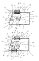
- FIG. 1 there is shown a lighting and / or signaling device 1 according to the invention which is intended to equip a motor vehicle, for the projection of a light beam on the road taken by the vehicle.
- This lighting and / or signaling device 1, called device 1 in the following description comprises a housing 2 and a transparent element 3 delimiting with the housing 2 an enclosure 4.
- the housing 2 is for example plastic material and has five walls: four side walls 5 interconnected to form an inner volume 7 and a bottom 6 located at one end of the side walls 5 and closing on one side the internal volume 7.
- the upper 5 "and the lower 5 'side walls extend in planes parallel to one another and substantially horizontal while the bottom 6 extends in a substantially vertical plane, c that is to say in a plane perpendicular to the planes in which the lower side walls 5 'and the upper side 5 "extend.
- the transparent element 3 is located at an end opposite the bottom 6 relative to the side walls.
- the transparent element 3 is, in particular, an ice 3 '. It thus closes the internal volume 7 and forms, with the four lateral walls 5 and the bottom 6 of the casing 2, the enclosure 4.
- the device further comprises a light source 8 and at least one radiator 9 in thermal and physical contact with the source 8.
- the source 8 and the radiator is located inside the enclosure 4, that is to say in the internal volume 7.
- the light source 8 comprises one or more light-emitting diodes, also called LEDs 8 '. These LEDs 8 'are fed by a control device 33 on which electronic components are located.
- the controller 33 is, for example, a printed circuit board comprising electronic components.
- the device 1 comprises at least one heat sink, called the first dissipator 14, which carries out a heat exchange between an air contained in the enclosure 4, called indoor air, and a flow of air outside the enclosure 4, represented by the arrow 30.
- the first dissipator 14 which carries out a heat exchange between an air contained in the enclosure 4, called indoor air, and a flow of air outside the enclosure 4, represented by the arrow 30.
- the radiator 9 and the first dissipator 14 are two separate parts.
- the radiator 9 and the first dissipator 14 are thus separated by the internal air present in the enclosure.
- the radiator heats the indoor air present in the chamber 4 while the first dissipator 14 cools it.
- a natural convection phenomenon is created between the radiator 9 which represents a hot surface and the first dissipator 14 which represents a cold surface.
- the interior air is thus caused to move in the enclosure of the radiator 9 to the first dissipator 14 to return to the radiator 9.
- An interior air flow represented by the arrow 28 is thus created inside the enclosure 4, that is to say in the internal volume 7. This air flow performs, in particular, a circulation loop between the radiator 9 and the first dissipator 14.
- this first dissipator 14 comprises a first series of fins 15, a second series of fins 16 and a base 17 interposed between the first series 15 and the second series 16.
- the first series of fins 15 extends in a surrounding volume where the flow of outside air circulates and the second series of fins 16 extends into the internal volume 7 delimited by the enclosure 4.
- the base 17 is, for example, made by a flat metal sheet or by a radiator, in particular a molded radiator. It is in contact, on the side of the first series of fins 15 with the surrounding volume in which the flow of outside air flows and on the side of the second series of fins 16 with the internal volume 7.
- the base 17 can to be reported, for example by screwing on the housing 2.
- a portion of the base 17, in particular, a peripheral portion of the base 17, is overmolded to the housing 2. That the base 17 is When the base 2 is fitted or overmolded, it has an opening in which the base 17 is positioned, the base 17 being in all cases secured to the housing 2.
- the sealing of the housing 2 at the level where the base 17 is located is ensured by at least one seal (not shown) or by the cooperation of the surfaces in contact between the base 17 and the housing 2.
- the first dissipator 14 is made unitarily, that is to say that its first series of fins 15, its second series of fins 16 and its base 17 are from the same material, in particular, metal so that they are in thermal contact.
- the first set of fins 15 is cooled by the outside air flow and in turn cools the base 17 and the second set of fins 16 in contact with the indoor air.
- the first dissipator may be devoid of series of fins if the heat to be dissipated from the LEDs 8 'does not justify it. It is also possible to adapt the number of fins of each series according to the heat to be dissipated. The greater the heat to be dissipated, the greater the number of fins on the outside, that is, the larger the first set of vanes comprises individual fins.
- the radiator 9 has a sensing portion 11 of heat released by the LEDs 8 'via the control device 33 and a dispersion portion 12 whose role is to disperse, in other words evacuate, this heat.
- the radiator 9 includes also a body 10 connecting the sensing portion 11 and the dispersion portion 12. This body 10 extends, in particular, horizontally, that is to say parallel to the lower side wall 5 'and upper 5 ".
- the sensing part 11 comprises thermal connections 11 ', thermally connecting the control device 33 of the LED 8' to the body 10 of the radiator 9. These thermal connections 11 'are, in particular, arms which extend transversely to the body 10 radiator 9 and which connect it thermally and physically to the control device 33.
- the control device 33 extends, for example, in a plane parallel to the plane in which the body 10 extends, that is to say in a horizontal plane.
- the light source 8 is located, in particular, on the control device 33 which then extends from the light source to the bottom 6 of the housing 2.
- the thermal connections 11 ', transverse to the body 10 and to the control device 33 thus extend in part between the light source 8 and the bottom 6.
- the dispersion portion 12 is, for example, located in the internal volume 7 delimited by the enclosure 4 at a distance from the ice 3 'of between 5 mm and 50 mm.
- This dispersion portion 12 comprises, in particular, fins 13 to improve the heat exchange with the internal air contained in the enclosure 4. These fins 13 extend transversely to the body 10 of the radiator 9 and are located near the ice 3 'so as to bring a maximum of heat near the ice 3' to limit condensation on the ice 3 '.
- the fins 13 may, in particular, be oriented vertically to direct the flow of indoor air and thus increase the cooling efficiency of the LEDs 8 'while further limiting condensation on the ice 3', from a volume of heated air near the ice 3 'more important.
- the radiator 9 is made of a single block, that is to say that the body 10, the sensing portion 11 and the dispersion portion 12 are made from the same material, for example, by molding.
- a conductive material This is, for example, aluminum or an aluminum alloy.
- the first dissipator 14 is positioned above the radiator 9 at the level of the upper side wall 5. It is situated, in particular, in the extension of the radiator 9 along an axis 29 parallel to the plane in which the transparent element extends. In other words, the axis 29 intersects both the radiator 9 and the first dissipator 14. In a complementary manner, the first dissipator 14 is located in the extension of the radiator 9 along an axis 36 perpendicular to the upper side wall 5 ". axis 36 being vertical and cutting both the radiator 9 and the first dissipator 14.
- the indoor air rises as it warms in contact with the radiator 9 and quickly descends after being cooled in contact with the first dissipator 14, thereby creating a natural convection phenomenon inside the enclosure 4.
- the interior air realizes and circulation loops and is called internal air flow, represented by the arrow 28, the air flow effecting these loops.
- Another advantage comes from the fact that by increasing the circulation velocity of the interior air flow, the rate of rise of hot air is increased in front of the transparent element 3 which ensures better demisting of the transparent element 3.
- the device further comprises a first conduit 18 disposed above the enclosure 4 and able to guide the flow of outside air to the first dissipator 14.
- the first conduit 18 is thus disposed on the upper side wall 5 "so that at least a portion of the base 17 and the first set of fins 15 are in the first duct 18.
- the first duct 18 channels the flow of outside air that can rush into it and cool the first dissipator 14 through the first set of fins 15.
- the outside air flow can then leave the first conduit 18 by a first discharge means 19 that includes the first conduit 18.
- This first evacuation means 19 is, in particular, a discharge orifice or, for example, a grid 19 '. This ensures a renewal of the outside air flow to improve the cooling of the first dissipator 14.
- the figure 2 illustrates a variant of the invention according to which the device 1 comprises a second heat sink 20.
- This second dissipator 20 is located, in particular, below the radiator 9 and performs a heat exchange between the air contained in the enclosure 4 and the external air flow 30.
- Such a second dissipator 20 is used in the case where the power to be dissipated and therefore the heat to be dissipated is greater.
- This second dissipator 20 is distinct from the first dissipator 14 and the radiator 9.
- the second dissipator 20 is located, in particular, below the radiator 9, at the level of the lower side wall 5 'so that it contributes to promoting the indoor air circulation.
- the second dissipator 20 comprises, as the first dissipator 14, a first series of fins 21, a second series of fins 22 and a base 23 interposed between the first series 21 and the second series 22.
- the base 23 is secured of the housing 2, for example, at the lower side wall 5 '.
- the first series of fins 21 thus extends into the surrounding volume where the flow of outside air circulates and the second series of fins 22 extends into the internal volume delimited by the enclosure 4.
- the first series of fins 21, the second set of fins 22 and the base 23 of the second dissipator 20 have the same characteristics as the first set of fins 15, the second set of fins 16 and the base 17 of the first dissipator 14.
- the second dissipator 20 is made in a unitary manner, that is to say that its first series of fins 21, its second series of fins 22 and its base 23 are from the same material, in particular, metal so that they are in thermal contact.
- the first set of fins 21 is cooled by the outside air flow and in turn cools the base 23 and the second set of fins 22 in contact with the indoor air.
- the device 1 comprises a second duct 24 disposed below the enclosure 4 and capable of guiding the flow of outside air towards the second dissipator 20. the same way as previously exposed for the first conduit 18.
- the second conduit 24 is thus disposed on the lower side wall 5 'so that at least a portion of the base 23 and the first set of fins 21 are located in the second duct 24.
- the outside air flow rushes into the second duct 24 and can cool the second dissipator 20 via the first set of fins 21.
- the outside air flow can then exit the second conduit 24 by a second discharge means 32 that includes the second conduit 24.
- This second discharge means 32 is, in particular, a discharge port or, for example, a gate 32 '. This ensures a renewal of the outside air flow to improve the cooling of the second dissipator 14.
- the presence of the first dissipator 14 and the second dissipator 20 thus makes it possible to increase the exchange capacity with the outside and thus to reduce the size and mass of the radiator 9.
- the figure 2 also allows to illustrate a variant of the invention according to which a thermal conduction means 25 is positioned between the radiator 9 and the second dissipator 20.
- the thermal conduction means 25 is a metal part making it possible to carry out a heat transfer of the radiator 9 to the second dissipator 20 to facilitate the cooling of the radiator 9.
- the heat conduction means 25 increases the capacity of the radiator 9 to dissipate the heat generated by the control device 33 of the LEDs 8 'and thus reduce the embedded mass of the radiator 9.
- the thermal conduction means 25 is a drain which directs the calories from the radiator directly to the second dissipator.
- a portion 26 of the dissipator (s) 14, 20 extends at a distance from the ice less than 50 mm.
- the first dissipator 14 the radiator 9 and the second dissipator 20 are cut by the axis 29 parallel to the plane in which the transparent element 3 extends and the axis 36 perpendicular to the upper side wall 5 ".
- the figure 3 illustrates an alternative embodiment of the invention according to which the base 17, 23 of the dissipator (s) 14, 20, has ventilations 27 adapted to circulating the outside air flow inside the enclosure 4.
- the ventilations 27 By placing the ventilations 27 on the base 17, 23 of the dissipator or heatsinks 14, 20, one thus takes advantage of the opening in the housing generated by these to install the heatsinks. In this way, it is avoided to provide an additional hole for ventilation of the internal volume 7.
- the arrow 31 represents the circulation of the outside air flow entered through the ventilation 27 inside the interior volume 7.
- the ventilation 27 are thus located below the radiator 9. These ventilations 27 make it possible to increase the circulation of air inside the chamber 4 by allowing the introduction of the outside air flow present in the second duct 24 to penetrate inside the volume 7.
- These ventilations 27 are, in particular, membranes welded to the housing 2 or on the ice 3 'or baffles with filter.
- the figure 4 illustrates an alternative embodiment in which the control device 33 is placed directly on the radiator, on an area close to the ice 3 ', that is to say an area located less than 50 mm from the ice 3'.
- the device 1 also comprises the first dissipator 14 and the radiator 9, but the latter does not have a dispersion portion 12 since the heat is directly released by the control device 33 in an area close to the ice 3 .
- the control device 33 thus makes it possible to bring heat close to the ice 3 'and to obtain the defogging of the ice 3'.
- the radiator 9 comprises the sensing zone 11 provided with the thermal connections 11 '.
- the figure 4 also allows to illustrate a mask 34 that comprises the device 1 and which extends between the light source 8 and the control device 33, the mask covering the latter. Its purpose is, in particular, to hide constituent elements of the device 1 such as the radiator 9 and the control device 33, so that they are not visible from the outside through the transparent element 3.
- the mask 34 could also be connected directly from the light source 8 to the radiator 9.
- control device 33 is disposed on the dissipation portion 12, near the ice 3 '.
- control device 33 is here located in the internal volume at a distance from the ice 3 'of between 5 mm and 50 mm. In this way, the heat generated by the control device 33 is used to create convective air flows closest to the ice 3 'in order to ensure the demisting of the condensation that can be created on an internal face of the transparent element 3.
Landscapes
- Engineering & Computer Science (AREA)
- General Engineering & Computer Science (AREA)
- Physics & Mathematics (AREA)
- Microelectronics & Electronic Packaging (AREA)
- Optics & Photonics (AREA)
- Cooling Or The Like Of Electrical Apparatus (AREA)
- Arrangement Of Elements, Cooling, Sealing, Or The Like Of Lighting Devices (AREA)
Applications Claiming Priority (1)
| Application Number | Priority Date | Filing Date | Title |
|---|---|---|---|
| FR1154949A FR2976345B1 (fr) | 2011-06-07 | 2011-06-07 | Dispositif d'eclairage et/ou de signalisation a radiateur et dissipateur integres |
Publications (3)
| Publication Number | Publication Date |
|---|---|
| EP2532949A2 true EP2532949A2 (de) | 2012-12-12 |
| EP2532949A3 EP2532949A3 (de) | 2013-03-20 |
| EP2532949B1 EP2532949B1 (de) | 2020-10-14 |
Family
ID=46149335
Family Applications (1)
| Application Number | Title | Priority Date | Filing Date |
|---|---|---|---|
| EP12170716.0A Active EP2532949B1 (de) | 2011-06-07 | 2012-06-04 | Beleuchtungs- und/oder Signalisierungsvorrichtung mit integriertem Wärmeableiter |
Country Status (2)
| Country | Link |
|---|---|
| EP (1) | EP2532949B1 (de) |
| FR (1) | FR2976345B1 (de) |
Cited By (1)
| Publication number | Priority date | Publication date | Assignee | Title |
|---|---|---|---|---|
| CN104456175A (zh) * | 2013-09-24 | 2015-03-25 | 株式会社东芝 | 照明设备 |
Family Cites Families (4)
| Publication number | Priority date | Publication date | Assignee | Title |
|---|---|---|---|---|
| US7275848B2 (en) * | 2005-02-16 | 2007-10-02 | Visteon Global Technologies, Inc. | Headlamp assembly having cooling channel |
| US7249868B2 (en) * | 2005-07-07 | 2007-07-31 | Visteon Global Technologies, Inc. | Lamp housing with interior cooling by a thermoelectric device |
| JP2007220618A (ja) * | 2006-02-20 | 2007-08-30 | Stanley Electric Co Ltd | 車両用led灯具 |
| US20090059594A1 (en) * | 2007-08-31 | 2009-03-05 | Ming-Feng Lin | Heat dissipating apparatus for automotive LED lamp |
-
2011
- 2011-06-07 FR FR1154949A patent/FR2976345B1/fr active Active
-
2012
- 2012-06-04 EP EP12170716.0A patent/EP2532949B1/de active Active
Non-Patent Citations (1)
| Title |
|---|
| None |
Cited By (2)
| Publication number | Priority date | Publication date | Assignee | Title |
|---|---|---|---|---|
| CN104456175A (zh) * | 2013-09-24 | 2015-03-25 | 株式会社东芝 | 照明设备 |
| US9410689B2 (en) | 2013-09-24 | 2016-08-09 | Kabushiki Kaisha Toshiba | Lighting apparatus |
Also Published As
| Publication number | Publication date |
|---|---|
| FR2976345B1 (fr) | 2015-05-01 |
| EP2532949B1 (de) | 2020-10-14 |
| FR2976345A1 (fr) | 2012-12-14 |
| EP2532949A3 (de) | 2013-03-20 |
Similar Documents
| Publication | Publication Date | Title |
|---|---|---|
| US7883251B2 (en) | System and method for heat dissipation from an automotive lighting assembly having a liquid cooling circuit | |
| EP1970622A1 (de) | Beleuchtungs- und/oder Signalisierungsvorrichtung für Kraftfahrzeug, die eine Außenwand mit Wärmeaustauschzone umfasst | |
| US7275848B2 (en) | Headlamp assembly having cooling channel | |
| CN209311970U (zh) | 液冷装置及具有该液冷装置的显示适配器 | |
| EP2199669B1 (de) | Vorrichtung zum Abkühlen eines optischen Moduls für einen Kraftfahrzeugscheinwerfer | |
| JP2007149696A (ja) | 冷却チャネルを有するヘッドランプ組立体 | |
| JP2009231511A (ja) | 筐体 | |
| EP3418630B1 (de) | Beleuchtungsmodul für kraftfahrzeug | |
| EP3273148A1 (de) | Fahrzeug-scheinwerfer | |
| FR2910779A1 (fr) | Boitier d'appareillage electronique a refroidissement par ventilation naturelle et forcee | |
| EP2306084A2 (de) | Vorrichtung zur Beleuchtung und/oder Signalisierung für Kraftfahrzeug | |
| EP2936954B1 (de) | Belüftungsvorrichtung für eine lüftungs-, heizungs- und/oder klimaanlage | |
| FR2998034A1 (fr) | Module d'eclairage a carte unitaire et dissipateurs distincts | |
| EP2532949B1 (de) | Beleuchtungs- und/oder Signalisierungsvorrichtung mit integriertem Wärmeableiter | |
| FR3058503A1 (fr) | Dispositif lumineux equipe d'au moins un element peltier | |
| EP3749537A1 (de) | Gebläsesteuermodul und entsprechende heizungs- und/oder belüftungs- und/oder klimaanlage | |
| WO2014095610A1 (fr) | Dispositif de refroidissement pour carte de circuit imprime | |
| FR2996905A1 (fr) | Dispositif lumineux avec refroidissement en plastique | |
| FR3075929A1 (fr) | Module lumineux pour vehicule comprenant un dispositif de ventilation dispose entre deux dispositifs de dissipation de chaleur | |
| EP2339232A1 (de) | Lampe für Scheinwerfer und Scheinwerfer mit einer solchen Lampe | |
| EP3002521A1 (de) | Kühlsystem für elektrischen schaltschrank | |
| EP4082306B1 (de) | Wärmeableitungsvorrichtung, elektrisches system mit einer solchen vorrichtung und zugehöriges herstellungsverfahren | |
| CN216010532U (zh) | 一种防雨摇头光束灯散热窗的防雨结构 | |
| CN207990524U (zh) | 车用固态光源灯泡 | |
| WO2013150227A1 (fr) | Lampe à diode électroluminescente |
Legal Events
| Date | Code | Title | Description |
|---|---|---|---|
| PUAI | Public reference made under article 153(3) epc to a published international application that has entered the european phase |
Free format text: ORIGINAL CODE: 0009012 |
|
| AK | Designated contracting states |
Kind code of ref document: A2 Designated state(s): AL AT BE BG CH CY CZ DE DK EE ES FI FR GB GR HR HU IE IS IT LI LT LU LV MC MK MT NL NO PL PT RO RS SE SI SK SM TR |
|
| AX | Request for extension of the european patent |
Extension state: BA ME |
|
| PUAL | Search report despatched |
Free format text: ORIGINAL CODE: 0009013 |
|
| AK | Designated contracting states |
Kind code of ref document: A3 Designated state(s): AL AT BE BG CH CY CZ DE DK EE ES FI FR GB GR HR HU IE IS IT LI LT LU LV MC MK MT NL NO PL PT RO RS SE SI SK SM TR |
|
| AX | Request for extension of the european patent |
Extension state: BA ME |
|
| RIC1 | Information provided on ipc code assigned before grant |
Ipc: F21W 101/02 20060101ALN20130208BHEP Ipc: F21S 8/10 20060101AFI20130208BHEP Ipc: F21Y 101/02 20060101ALN20130208BHEP Ipc: F21V 29/00 20060101ALI20130208BHEP |
|
| 17P | Request for examination filed |
Effective date: 20130919 |
|
| RBV | Designated contracting states (corrected) |
Designated state(s): AL AT BE BG CH CY CZ DE DK EE ES FI FR GB GR HR HU IE IS IT LI LT LU LV MC MK MT NL NO PL PT RO RS SE SI SK SM TR |
|
| REG | Reference to a national code |
Ref country code: DE Ref legal event code: R079 Ref document number: 602012072769 Country of ref document: DE Free format text: PREVIOUS MAIN CLASS: F21S0008100000 Ipc: F21S0041140000 |
|
| RIC1 | Information provided on ipc code assigned before grant |
Ipc: F21V 29/00 20150101ALI20200108BHEP Ipc: F21S 45/47 20180101ALI20200108BHEP Ipc: F21S 43/14 20180101ALI20200108BHEP Ipc: F21S 41/14 20180101AFI20200108BHEP |
|
| GRAP | Despatch of communication of intention to grant a patent |
Free format text: ORIGINAL CODE: EPIDOSNIGR1 |
|
| STAA | Information on the status of an ep patent application or granted ep patent |
Free format text: STATUS: GRANT OF PATENT IS INTENDED |
|
| INTG | Intention to grant announced |
Effective date: 20200319 |
|
| GRAJ | Information related to disapproval of communication of intention to grant by the applicant or resumption of examination proceedings by the epo deleted |
Free format text: ORIGINAL CODE: EPIDOSDIGR1 |
|
| STAA | Information on the status of an ep patent application or granted ep patent |
Free format text: STATUS: REQUEST FOR EXAMINATION WAS MADE |
|
| INTC | Intention to grant announced (deleted) | ||
| GRAR | Information related to intention to grant a patent recorded |
Free format text: ORIGINAL CODE: EPIDOSNIGR71 |
|
| GRAS | Grant fee paid |
Free format text: ORIGINAL CODE: EPIDOSNIGR3 |
|
| STAA | Information on the status of an ep patent application or granted ep patent |
Free format text: STATUS: GRANT OF PATENT IS INTENDED |
|
| GRAA | (expected) grant |
Free format text: ORIGINAL CODE: 0009210 |
|
| STAA | Information on the status of an ep patent application or granted ep patent |
Free format text: STATUS: THE PATENT HAS BEEN GRANTED |
|
| AK | Designated contracting states |
Kind code of ref document: B1 Designated state(s): AL AT BE BG CH CY CZ DE DK EE ES FI FR GB GR HR HU IE IS IT LI LT LU LV MC MK MT NL NO PL PT RO RS SE SI SK SM TR |
|
| INTG | Intention to grant announced |
Effective date: 20200907 |
|
| REG | Reference to a national code |
Ref country code: GB Ref legal event code: FG4D Free format text: NOT ENGLISH |
|
| REG | Reference to a national code |
Ref country code: AT Ref legal event code: REF Ref document number: 1323937 Country of ref document: AT Kind code of ref document: T Effective date: 20201015 Ref country code: CH Ref legal event code: EP |
|
| REG | Reference to a national code |
Ref country code: DE Ref legal event code: R096 Ref document number: 602012072769 Country of ref document: DE |
|
| REG | Reference to a national code |
Ref country code: IE Ref legal event code: FG4D Free format text: LANGUAGE OF EP DOCUMENT: FRENCH |
|
| REG | Reference to a national code |
Ref country code: AT Ref legal event code: MK05 Ref document number: 1323937 Country of ref document: AT Kind code of ref document: T Effective date: 20201014 |
|
| REG | Reference to a national code |
Ref country code: NL Ref legal event code: MP Effective date: 20201014 |
|
| PG25 | Lapsed in a contracting state [announced via postgrant information from national office to epo] |
Ref country code: NL Free format text: LAPSE BECAUSE OF FAILURE TO SUBMIT A TRANSLATION OF THE DESCRIPTION OR TO PAY THE FEE WITHIN THE PRESCRIBED TIME-LIMIT Effective date: 20201014 Ref country code: PT Free format text: LAPSE BECAUSE OF FAILURE TO SUBMIT A TRANSLATION OF THE DESCRIPTION OR TO PAY THE FEE WITHIN THE PRESCRIBED TIME-LIMIT Effective date: 20210215 Ref country code: NO Free format text: LAPSE BECAUSE OF FAILURE TO SUBMIT A TRANSLATION OF THE DESCRIPTION OR TO PAY THE FEE WITHIN THE PRESCRIBED TIME-LIMIT Effective date: 20210114 Ref country code: RS Free format text: LAPSE BECAUSE OF FAILURE TO SUBMIT A TRANSLATION OF THE DESCRIPTION OR TO PAY THE FEE WITHIN THE PRESCRIBED TIME-LIMIT Effective date: 20201014 Ref country code: FI Free format text: LAPSE BECAUSE OF FAILURE TO SUBMIT A TRANSLATION OF THE DESCRIPTION OR TO PAY THE FEE WITHIN THE PRESCRIBED TIME-LIMIT Effective date: 20201014 Ref country code: GR Free format text: LAPSE BECAUSE OF FAILURE TO SUBMIT A TRANSLATION OF THE DESCRIPTION OR TO PAY THE FEE WITHIN THE PRESCRIBED TIME-LIMIT Effective date: 20210115 |
|
| REG | Reference to a national code |
Ref country code: LT Ref legal event code: MG4D |
|
| PG25 | Lapsed in a contracting state [announced via postgrant information from national office to epo] |
Ref country code: PL Free format text: LAPSE BECAUSE OF FAILURE TO SUBMIT A TRANSLATION OF THE DESCRIPTION OR TO PAY THE FEE WITHIN THE PRESCRIBED TIME-LIMIT Effective date: 20201014 Ref country code: LV Free format text: LAPSE BECAUSE OF FAILURE TO SUBMIT A TRANSLATION OF THE DESCRIPTION OR TO PAY THE FEE WITHIN THE PRESCRIBED TIME-LIMIT Effective date: 20201014 Ref country code: SE Free format text: LAPSE BECAUSE OF FAILURE TO SUBMIT A TRANSLATION OF THE DESCRIPTION OR TO PAY THE FEE WITHIN THE PRESCRIBED TIME-LIMIT Effective date: 20201014 Ref country code: IS Free format text: LAPSE BECAUSE OF FAILURE TO SUBMIT A TRANSLATION OF THE DESCRIPTION OR TO PAY THE FEE WITHIN THE PRESCRIBED TIME-LIMIT Effective date: 20210214 Ref country code: ES Free format text: LAPSE BECAUSE OF FAILURE TO SUBMIT A TRANSLATION OF THE DESCRIPTION OR TO PAY THE FEE WITHIN THE PRESCRIBED TIME-LIMIT Effective date: 20201014 Ref country code: BG Free format text: LAPSE BECAUSE OF FAILURE TO SUBMIT A TRANSLATION OF THE DESCRIPTION OR TO PAY THE FEE WITHIN THE PRESCRIBED TIME-LIMIT Effective date: 20210114 Ref country code: AT Free format text: LAPSE BECAUSE OF FAILURE TO SUBMIT A TRANSLATION OF THE DESCRIPTION OR TO PAY THE FEE WITHIN THE PRESCRIBED TIME-LIMIT Effective date: 20201014 |
|
| PG25 | Lapsed in a contracting state [announced via postgrant information from national office to epo] |
Ref country code: HR Free format text: LAPSE BECAUSE OF FAILURE TO SUBMIT A TRANSLATION OF THE DESCRIPTION OR TO PAY THE FEE WITHIN THE PRESCRIBED TIME-LIMIT Effective date: 20201014 |
|
| REG | Reference to a national code |
Ref country code: DE Ref legal event code: R097 Ref document number: 602012072769 Country of ref document: DE |
|
| PG25 | Lapsed in a contracting state [announced via postgrant information from national office to epo] |
Ref country code: RO Free format text: LAPSE BECAUSE OF FAILURE TO SUBMIT A TRANSLATION OF THE DESCRIPTION OR TO PAY THE FEE WITHIN THE PRESCRIBED TIME-LIMIT Effective date: 20201014 Ref country code: SK Free format text: LAPSE BECAUSE OF FAILURE TO SUBMIT A TRANSLATION OF THE DESCRIPTION OR TO PAY THE FEE WITHIN THE PRESCRIBED TIME-LIMIT Effective date: 20201014 Ref country code: LT Free format text: LAPSE BECAUSE OF FAILURE TO SUBMIT A TRANSLATION OF THE DESCRIPTION OR TO PAY THE FEE WITHIN THE PRESCRIBED TIME-LIMIT Effective date: 20201014 Ref country code: SM Free format text: LAPSE BECAUSE OF FAILURE TO SUBMIT A TRANSLATION OF THE DESCRIPTION OR TO PAY THE FEE WITHIN THE PRESCRIBED TIME-LIMIT Effective date: 20201014 Ref country code: CZ Free format text: LAPSE BECAUSE OF FAILURE TO SUBMIT A TRANSLATION OF THE DESCRIPTION OR TO PAY THE FEE WITHIN THE PRESCRIBED TIME-LIMIT Effective date: 20201014 Ref country code: EE Free format text: LAPSE BECAUSE OF FAILURE TO SUBMIT A TRANSLATION OF THE DESCRIPTION OR TO PAY THE FEE WITHIN THE PRESCRIBED TIME-LIMIT Effective date: 20201014 |
|
| PLBE | No opposition filed within time limit |
Free format text: ORIGINAL CODE: 0009261 |
|
| STAA | Information on the status of an ep patent application or granted ep patent |
Free format text: STATUS: NO OPPOSITION FILED WITHIN TIME LIMIT |
|
| PG25 | Lapsed in a contracting state [announced via postgrant information from national office to epo] |
Ref country code: DK Free format text: LAPSE BECAUSE OF FAILURE TO SUBMIT A TRANSLATION OF THE DESCRIPTION OR TO PAY THE FEE WITHIN THE PRESCRIBED TIME-LIMIT Effective date: 20201014 |
|
| 26N | No opposition filed |
Effective date: 20210715 |
|
| PG25 | Lapsed in a contracting state [announced via postgrant information from national office to epo] |
Ref country code: IT Free format text: LAPSE BECAUSE OF FAILURE TO SUBMIT A TRANSLATION OF THE DESCRIPTION OR TO PAY THE FEE WITHIN THE PRESCRIBED TIME-LIMIT Effective date: 20201014 Ref country code: AL Free format text: LAPSE BECAUSE OF FAILURE TO SUBMIT A TRANSLATION OF THE DESCRIPTION OR TO PAY THE FEE WITHIN THE PRESCRIBED TIME-LIMIT Effective date: 20201014 |
|
| PG25 | Lapsed in a contracting state [announced via postgrant information from national office to epo] |
Ref country code: SI Free format text: LAPSE BECAUSE OF FAILURE TO SUBMIT A TRANSLATION OF THE DESCRIPTION OR TO PAY THE FEE WITHIN THE PRESCRIBED TIME-LIMIT Effective date: 20201014 |
|
| PG25 | Lapsed in a contracting state [announced via postgrant information from national office to epo] |
Ref country code: MC Free format text: LAPSE BECAUSE OF FAILURE TO SUBMIT A TRANSLATION OF THE DESCRIPTION OR TO PAY THE FEE WITHIN THE PRESCRIBED TIME-LIMIT Effective date: 20201014 |
|
| REG | Reference to a national code |
Ref country code: CH Ref legal event code: PL |
|
| GBPC | Gb: european patent ceased through non-payment of renewal fee |
Effective date: 20210604 |
|
| REG | Reference to a national code |
Ref country code: BE Ref legal event code: MM Effective date: 20210630 |
|
| PG25 | Lapsed in a contracting state [announced via postgrant information from national office to epo] |
Ref country code: LU Free format text: LAPSE BECAUSE OF NON-PAYMENT OF DUE FEES Effective date: 20210604 |
|
| PG25 | Lapsed in a contracting state [announced via postgrant information from national office to epo] |
Ref country code: LI Free format text: LAPSE BECAUSE OF NON-PAYMENT OF DUE FEES Effective date: 20210630 Ref country code: IE Free format text: LAPSE BECAUSE OF NON-PAYMENT OF DUE FEES Effective date: 20210604 Ref country code: GB Free format text: LAPSE BECAUSE OF NON-PAYMENT OF DUE FEES Effective date: 20210604 Ref country code: CH Free format text: LAPSE BECAUSE OF NON-PAYMENT OF DUE FEES Effective date: 20210630 |
|
| PG25 | Lapsed in a contracting state [announced via postgrant information from national office to epo] |
Ref country code: IS Free format text: LAPSE BECAUSE OF FAILURE TO SUBMIT A TRANSLATION OF THE DESCRIPTION OR TO PAY THE FEE WITHIN THE PRESCRIBED TIME-LIMIT Effective date: 20210214 |
|
| PG25 | Lapsed in a contracting state [announced via postgrant information from national office to epo] |
Ref country code: BE Free format text: LAPSE BECAUSE OF NON-PAYMENT OF DUE FEES Effective date: 20210630 |
|
| PG25 | Lapsed in a contracting state [announced via postgrant information from national office to epo] |
Ref country code: HU Free format text: LAPSE BECAUSE OF FAILURE TO SUBMIT A TRANSLATION OF THE DESCRIPTION OR TO PAY THE FEE WITHIN THE PRESCRIBED TIME-LIMIT; INVALID AB INITIO Effective date: 20120604 Ref country code: CY Free format text: LAPSE BECAUSE OF FAILURE TO SUBMIT A TRANSLATION OF THE DESCRIPTION OR TO PAY THE FEE WITHIN THE PRESCRIBED TIME-LIMIT Effective date: 20201014 |
|
| P01 | Opt-out of the competence of the unified patent court (upc) registered |
Effective date: 20230528 |
|
| PG25 | Lapsed in a contracting state [announced via postgrant information from national office to epo] |
Ref country code: MK Free format text: LAPSE BECAUSE OF FAILURE TO SUBMIT A TRANSLATION OF THE DESCRIPTION OR TO PAY THE FEE WITHIN THE PRESCRIBED TIME-LIMIT Effective date: 20201014 |
|
| PG25 | Lapsed in a contracting state [announced via postgrant information from national office to epo] |
Ref country code: MT Free format text: LAPSE BECAUSE OF FAILURE TO SUBMIT A TRANSLATION OF THE DESCRIPTION OR TO PAY THE FEE WITHIN THE PRESCRIBED TIME-LIMIT Effective date: 20201014 |
|
| PGFP | Annual fee paid to national office [announced via postgrant information from national office to epo] |
Ref country code: DE Payment date: 20250617 Year of fee payment: 14 |
|
| PGFP | Annual fee paid to national office [announced via postgrant information from national office to epo] |
Ref country code: FR Payment date: 20250630 Year of fee payment: 14 |
|
| PG25 | Lapsed in a contracting state [announced via postgrant information from national office to epo] |
Ref country code: TR Free format text: LAPSE BECAUSE OF FAILURE TO SUBMIT A TRANSLATION OF THE DESCRIPTION OR TO PAY THE FEE WITHIN THE PRESCRIBED TIME-LIMIT Effective date: 20201014 |