EP2532890A1 - Regenerated energy electricity generation device - Google Patents
Regenerated energy electricity generation device Download PDFInfo
- Publication number
- EP2532890A1 EP2532890A1 EP11810981A EP11810981A EP2532890A1 EP 2532890 A1 EP2532890 A1 EP 2532890A1 EP 11810981 A EP11810981 A EP 11810981A EP 11810981 A EP11810981 A EP 11810981A EP 2532890 A1 EP2532890 A1 EP 2532890A1
- Authority
- EP
- European Patent Office
- Prior art keywords
- piping
- cooling
- heat exchanger
- operating
- tower
- Prior art date
- Legal status (The legal status is an assumption and is not a legal conclusion. Google has not performed a legal analysis and makes no representation as to the accuracy of the status listed.)
- Withdrawn
Links
Images





Classifications
-
- F—MECHANICAL ENGINEERING; LIGHTING; HEATING; WEAPONS; BLASTING
- F03—MACHINES OR ENGINES FOR LIQUIDS; WIND, SPRING, OR WEIGHT MOTORS; PRODUCING MECHANICAL POWER OR A REACTIVE PROPULSIVE THRUST, NOT OTHERWISE PROVIDED FOR
- F03D—WIND MOTORS
- F03D13/00—Assembly, mounting or commissioning of wind motors; Arrangements specially adapted for transporting wind motor components
- F03D13/10—Assembly of wind motors; Arrangements for erecting wind motors
-
- F—MECHANICAL ENGINEERING; LIGHTING; HEATING; WEAPONS; BLASTING
- F03—MACHINES OR ENGINES FOR LIQUIDS; WIND, SPRING, OR WEIGHT MOTORS; PRODUCING MECHANICAL POWER OR A REACTIVE PROPULSIVE THRUST, NOT OTHERWISE PROVIDED FOR
- F03D—WIND MOTORS
- F03D80/00—Details, components or accessories not provided for in groups F03D1/00 - F03D17/00
- F03D80/60—Cooling or heating of wind motors
-
- F—MECHANICAL ENGINEERING; LIGHTING; HEATING; WEAPONS; BLASTING
- F03—MACHINES OR ENGINES FOR LIQUIDS; WIND, SPRING, OR WEIGHT MOTORS; PRODUCING MECHANICAL POWER OR A REACTIVE PROPULSIVE THRUST, NOT OTHERWISE PROVIDED FOR
- F03D—WIND MOTORS
- F03D80/00—Details, components or accessories not provided for in groups F03D1/00 - F03D17/00
- F03D80/70—Bearing or lubricating arrangements
-
- F—MECHANICAL ENGINEERING; LIGHTING; HEATING; WEAPONS; BLASTING
- F03—MACHINES OR ENGINES FOR LIQUIDS; WIND, SPRING, OR WEIGHT MOTORS; PRODUCING MECHANICAL POWER OR A REACTIVE PROPULSIVE THRUST, NOT OTHERWISE PROVIDED FOR
- F03D—WIND MOTORS
- F03D80/00—Details, components or accessories not provided for in groups F03D1/00 - F03D17/00
- F03D80/80—Arrangement of components within nacelles or towers
-
- F—MECHANICAL ENGINEERING; LIGHTING; HEATING; WEAPONS; BLASTING
- F28—HEAT EXCHANGE IN GENERAL
- F28D—HEAT-EXCHANGE APPARATUS, NOT PROVIDED FOR IN ANOTHER SUBCLASS, IN WHICH THE HEAT-EXCHANGE MEDIA DO NOT COME INTO DIRECT CONTACT
- F28D1/00—Heat-exchange apparatus having stationary conduit assemblies for one heat-exchange medium only, the media being in contact with different sides of the conduit wall, in which the other heat-exchange medium is a large body of fluid, e.g. domestic or motor car radiators
- F28D1/02—Heat-exchange apparatus having stationary conduit assemblies for one heat-exchange medium only, the media being in contact with different sides of the conduit wall, in which the other heat-exchange medium is a large body of fluid, e.g. domestic or motor car radiators with heat-exchange conduits immersed in the body of fluid
- F28D1/0206—Heat exchangers immersed in a large body of liquid
- F28D1/022—Heat exchangers immersed in a large body of liquid for immersion in a natural body of water, e.g. marine radiators
-
- F—MECHANICAL ENGINEERING; LIGHTING; HEATING; WEAPONS; BLASTING
- F05—INDEXING SCHEMES RELATING TO ENGINES OR PUMPS IN VARIOUS SUBCLASSES OF CLASSES F01-F04
- F05B—INDEXING SCHEME RELATING TO WIND, SPRING, WEIGHT, INERTIA OR LIKE MOTORS, TO MACHINES OR ENGINES FOR LIQUIDS COVERED BY SUBCLASSES F03B, F03D AND F03G
- F05B2230/00—Manufacture
- F05B2230/60—Assembly methods
- F05B2230/61—Assembly methods using auxiliary equipment for lifting or holding
-
- F—MECHANICAL ENGINEERING; LIGHTING; HEATING; WEAPONS; BLASTING
- F05—INDEXING SCHEMES RELATING TO ENGINES OR PUMPS IN VARIOUS SUBCLASSES OF CLASSES F01-F04
- F05B—INDEXING SCHEME RELATING TO WIND, SPRING, WEIGHT, INERTIA OR LIKE MOTORS, TO MACHINES OR ENGINES FOR LIQUIDS COVERED BY SUBCLASSES F03B, F03D AND F03G
- F05B2240/00—Components
- F05B2240/90—Mounting on supporting structures or systems
- F05B2240/91—Mounting on supporting structures or systems on a stationary structure
- F05B2240/916—Mounting on supporting structures or systems on a stationary structure with provision for hoisting onto the structure
-
- F—MECHANICAL ENGINEERING; LIGHTING; HEATING; WEAPONS; BLASTING
- F05—INDEXING SCHEMES RELATING TO ENGINES OR PUMPS IN VARIOUS SUBCLASSES OF CLASSES F01-F04
- F05B—INDEXING SCHEME RELATING TO WIND, SPRING, WEIGHT, INERTIA OR LIKE MOTORS, TO MACHINES OR ENGINES FOR LIQUIDS COVERED BY SUBCLASSES F03B, F03D AND F03G
- F05B2240/00—Components
- F05B2240/90—Mounting on supporting structures or systems
- F05B2240/95—Mounting on supporting structures or systems offshore
-
- F—MECHANICAL ENGINEERING; LIGHTING; HEATING; WEAPONS; BLASTING
- F05—INDEXING SCHEMES RELATING TO ENGINES OR PUMPS IN VARIOUS SUBCLASSES OF CLASSES F01-F04
- F05B—INDEXING SCHEME RELATING TO WIND, SPRING, WEIGHT, INERTIA OR LIKE MOTORS, TO MACHINES OR ENGINES FOR LIQUIDS COVERED BY SUBCLASSES F03B, F03D AND F03G
- F05B2260/00—Function
- F05B2260/20—Heat transfer, e.g. cooling
-
- Y—GENERAL TAGGING OF NEW TECHNOLOGICAL DEVELOPMENTS; GENERAL TAGGING OF CROSS-SECTIONAL TECHNOLOGIES SPANNING OVER SEVERAL SECTIONS OF THE IPC; TECHNICAL SUBJECTS COVERED BY FORMER USPC CROSS-REFERENCE ART COLLECTIONS [XRACs] AND DIGESTS
- Y02—TECHNOLOGIES OR APPLICATIONS FOR MITIGATION OR ADAPTATION AGAINST CLIMATE CHANGE
- Y02E—REDUCTION OF GREENHOUSE GAS [GHG] EMISSIONS, RELATED TO ENERGY GENERATION, TRANSMISSION OR DISTRIBUTION
- Y02E10/00—Energy generation through renewable energy sources
- Y02E10/70—Wind energy
- Y02E10/72—Wind turbines with rotation axis in wind direction
-
- Y—GENERAL TAGGING OF NEW TECHNOLOGICAL DEVELOPMENTS; GENERAL TAGGING OF CROSS-SECTIONAL TECHNOLOGIES SPANNING OVER SEVERAL SECTIONS OF THE IPC; TECHNICAL SUBJECTS COVERED BY FORMER USPC CROSS-REFERENCE ART COLLECTIONS [XRACs] AND DIGESTS
- Y02—TECHNOLOGIES OR APPLICATIONS FOR MITIGATION OR ADAPTATION AGAINST CLIMATE CHANGE
- Y02E—REDUCTION OF GREENHOUSE GAS [GHG] EMISSIONS, RELATED TO ENERGY GENERATION, TRANSMISSION OR DISTRIBUTION
- Y02E10/00—Energy generation through renewable energy sources
- Y02E10/70—Wind energy
- Y02E10/727—Offshore wind turbines
-
- Y—GENERAL TAGGING OF NEW TECHNOLOGICAL DEVELOPMENTS; GENERAL TAGGING OF CROSS-SECTIONAL TECHNOLOGIES SPANNING OVER SEVERAL SECTIONS OF THE IPC; TECHNICAL SUBJECTS COVERED BY FORMER USPC CROSS-REFERENCE ART COLLECTIONS [XRACs] AND DIGESTS
- Y02—TECHNOLOGIES OR APPLICATIONS FOR MITIGATION OR ADAPTATION AGAINST CLIMATE CHANGE
- Y02E—REDUCTION OF GREENHOUSE GAS [GHG] EMISSIONS, RELATED TO ENERGY GENERATION, TRANSMISSION OR DISTRIBUTION
- Y02E10/00—Energy generation through renewable energy sources
- Y02E10/70—Wind energy
- Y02E10/728—Onshore wind turbines
-
- Y—GENERAL TAGGING OF NEW TECHNOLOGICAL DEVELOPMENTS; GENERAL TAGGING OF CROSS-SECTIONAL TECHNOLOGIES SPANNING OVER SEVERAL SECTIONS OF THE IPC; TECHNICAL SUBJECTS COVERED BY FORMER USPC CROSS-REFERENCE ART COLLECTIONS [XRACs] AND DIGESTS
- Y02—TECHNOLOGIES OR APPLICATIONS FOR MITIGATION OR ADAPTATION AGAINST CLIMATE CHANGE
- Y02P—CLIMATE CHANGE MITIGATION TECHNOLOGIES IN THE PRODUCTION OR PROCESSING OF GOODS
- Y02P70/00—Climate change mitigation technologies in the production process for final industrial or consumer products
- Y02P70/50—Manufacturing or production processes characterised by the final manufactured product
-
- Y—GENERAL TAGGING OF NEW TECHNOLOGICAL DEVELOPMENTS; GENERAL TAGGING OF CROSS-SECTIONAL TECHNOLOGIES SPANNING OVER SEVERAL SECTIONS OF THE IPC; TECHNICAL SUBJECTS COVERED BY FORMER USPC CROSS-REFERENCE ART COLLECTIONS [XRACs] AND DIGESTS
- Y02—TECHNOLOGIES OR APPLICATIONS FOR MITIGATION OR ADAPTATION AGAINST CLIMATE CHANGE
- Y02P—CLIMATE CHANGE MITIGATION TECHNOLOGIES IN THE PRODUCTION OR PROCESSING OF GOODS
- Y02P80/00—Climate change mitigation technologies for sector-wide applications
- Y02P80/10—Efficient use of energy, e.g. using compressed air or pressurized fluid as energy carrier
Definitions
- the present invention relates to a power generating apparatus of renewable energy type which transmits rotation energy of a rotor from a renewable energy source to a generator, particularly a power generating apparatus of a renewable energy type having a function of cooling a hydraulic transmission.
- power generating apparatuses of a renewable energy type such as a wind turbine generator using wind power and a tidal generator using tidal current, river current or ocean current energy are becoming popular.
- a renewable energy type such as a wind turbine generator using wind power and a tidal generator using tidal current, river current or ocean current energy
- wind turbine generators installed offshore are expensive to construct in comparison to those installed onshore and thus, it is desired to improve power generation efficiency by increasing the size of the wind turbine generator so as to improve profitability.
- Patent Literature 1 As the power generating apparatus of renewable energy type equipped with the hydraulic transmission, a wind turbine generator having a hydraulic pump, a hydraulic motor and a generator in a nacelle is introduced in Patent Literature 1, for example, In the wind turbine generator, a rotation energy of a rotor is transmitted to the generator via the hydraulic transmission (see Fig.7 of Patent Literature 1).
- a wind turbine generator disclosed in Patent Literature 2 has a hydraulic pump installed in the nacelle, and a hydraulic motor and a generator installed at a bottom of a tower and the hydraulic pump and the hydraulic motor are connected by a piping.
- Patent Literature 3 proposes a wind turbine generator having a cooling system for cooling a converter, a transformer and a control unit.
- the cooling system includes a plurality of heat exchangers installed around a tower.
- a cooling medium having cooled the converter, the converter, the transformer and the control unit is cooled by heat exchange with atmospheric air.
- Patent Literature 4 discloses a cooling device for a wind turbine generator.
- the cooling device has a heat exchanger to cool a plurality of devices such as a converter, a transformer, a bearing box and a generator. Cooling water cools the devices and then is cooled by the heat exchanger installed on an outer wall of a tower and a nacelle.
- a power generating apparatus of renewable energy type which generates electric power from renewable energy such as wind power, tidal current, river current and ocean current, is installed where there is significant temperature change of a surrounding environment such as temperature of ambient air, water and so on.
- the viscosity of the operating oil changes in accordance with the temperature change.
- the viscosity of the operating oil becomes high, resulting in significant energy loss in the hydraulic transmission.
- the viscosity of the operating oil decreases, resulting in accelerating degradation of the operating oil. This leads to a decline of the lubricating property, wear of the sliding part and leaking of the operating oil. Therefore, in the power generating apparatus installed with the hydraulic transmission, it is desired to keep the operating oil at an appropriate temperature.
- such technique is not disclosed in the prior art such as Patent Literatures 3 and 4.
- Patent Literatures 3 and 4 cool the cooling medium by heat exchange with ambient air after the cooling medium is used to cool the heat generating source.
- air-cooling in general does not have high heat-exchange efficiency compared to water cooling.
- it is an object of the present invention is to provide a power generating apparatus of renewable energy type installed with a cooling mechanism which is capable of efficiently cooling the operating oil of the hydraulic transmission.
- a power generating apparatus of renewable energy type which generates power from renewable energy may include, but is not limited to: a tower; a nacelle which is supported rotatably by a tip portion of the tower; a main shaft which is housed in the nacelle and rotates with a blade; a hydraulic pump which is housed in the nacelle and is driven by rotation of the main shaft; a hydraulic motor which is driven by operating oil supplied from the hydraulic pump; a generator which is coupled to the hydraulic motor; an operating-oil line which is provided between the hydraulic pump and the hydraulic motor and through which the operating oil circulates; a cooling-medium line through which cooling medium for cooling the operating oil circulates via an intermediate heat exchanger; and a main heat exchanger which cools the cooling medium by heat exchange with cool water source which is one of sea water, lake water, river water and groundwater around a base portion of the tower, and one of the operating-oil line and the cooling-medium line may include, but is not limited to: a first
- the cooling medium used to cool the operating oil is cooled by heat exchange with the cool water source which is one of sea water, lake water, river water and groundwater around the base portion of the tower and thus, the cooling medium can be cooled by the cool water with high efficiency.
- the cool water source which is one of sea water, lake water, river water and groundwater around the base portion of the tower and thus, the cooling medium can be cooled by the cool water with high efficiency.
- one of the operating-oil line and the cooling-medium line is divided into the first piping supported on the nacelle side and the second piping supported on the tower side and the first piping and the second piping are arranged relatively rotatable with each other by means of the connection part having the swivel structure. Therefore, even when the nacelle turns, the fluid can communicate smoothly between the first piping on the nacelle side and the second piping on the tower side
- the hydraulic motor may be provided between the tip portion and the base portion of the tower, the operating-oil line may extend between the hydraulic pump arranged in the nacelle and the hydraulic motor arranged in the tower, the operating-oil line may include the first piping, the second piping and the connection part, and the first piping may be connected to the hydraulic pump and the second piping is connected to the hydraulic motor.
- the operating-oil line extends to the tower side.
- the heat exchange can be performed between the operating oil and the cooling medium in the tower. Therefore, it is no longer necessary to extend the cooling-medium line for coo l ing the operating oil to the nacelle.
- the coo l ing medium is pumped to the nacelle height by the cooling-medium line, it is possible to reduce the input of the pump and to downsize the pump.
- the hydraulic motor may be supported on the nacelle side and the intermediate heat exchanger is supported on the tower side
- the operating-oil line may include an operating-oil circulation line through which the operating oil circulates between the hydraulic pump and the hydraulic motor, and an operating-oil branch line which branches from a low-pressure side of the operating-oil circulation line and through which the operating-oil line returns to the operating-oil circulation line via the intermediate heat exchanger
- the operating-oil branch line may include the first piping, the second piping and the connection part, and the first piping may be connected to the operating-oil circulation line and the second piping is connected to the intermediate heat exchanger.
- the operating-oil circulation line where the flow amount of the operating oil is large can be shorter while reducing the flow amount of the operating oil passing through the connection part.
- the piping structure can be simplified.
- the operating-oil branch line branches from the low pressure side of the operating-oil circulation line and thus, the operating-oil branch line and the connection part 100 can be formed by a piping of low pressure-resistance, resulting in cost reduction.
- the hydraulic motor and the generator may be arranged in the nacelle and the intermediate heat exchanger is supported on the nacelle side
- the cooling-medium line may include the first piping, the second piping and the connection part
- the first piping may be connected to an intermediate heat exchanger side and the second piping is connected to a main heat exchanger side.
- the above power generating apparatus of renewable energy type may include, but is not limited to: at least one first flow path in which fluid flows from the nacelle side to the tower side; at least one second flow path in which fluid flows from the tower side to the nacelle side; a tubular member in which the at least one first flow and the at least one second flow path are formed; a first jacket which is provided around the tubular member and which includes a circular flow path which communicates with the first piping through a first communication opening; and a second jacket which is provided around the tubular member and which includes a circular flow path which communicates with the second piping through a second communication opening, and the first jacket and the second jacket are fixed to the tubular member via a bearing to be freely rotatable relative to the tubular member.
- the fluid flowing from the nacelle side to the tower side enters the first flow path formed in the tubular member via the first communication opening from the circular flow path of the first jacket connected to the first piping so as to flow from the first flow path to the second piping. Meanwhile, the fluid flowing from the tower side to the nacelle side, enters the second flow path formed in the tubular member via the second communication opening from the circular path of the second jacket connected to the second piping so as to flow from the second flow path to the first piping.
- the first jacket and the second jacket are arranged relatively rotatable with respect to the tubular member via the bearing and thus, the relative rotation between the piping on the nacelle side and the piping on the tower side while securing the flow of the fluid flowing from the nacelle side to the tower side and the flow of the fluid flowing from the tower side to the nacelle side and the flow of the fluid
- the tubular member may have a cable-housing piping on an inner side of the first and second flow paths, the cable-housing piping housing a cable extending from the nacelle side to the tower side.
- the above power generating apparatus of renewable energy type may include, but is not limited to: a water supply source which supplies water to the cooling-medium line; and a pump which circulates cooling-medium in the cooling-medium line, the cooling-medium being formed by adding antifreeze to the water.
- a flow rate of the circulating cooling medium can be regulated, for instance, in accordance with a temperature change of the ambient air or the like and the operating oil can be maintained at a constant temperature.
- the cooling medium being formed by adding antifreeze to the water, even when the ambient air becomes not greater than a freezing temperature of the water, freezing of the cooling-medium is prevented and thus, the smooth operation of the cooling mechanism can be achieved.
- the water supply source may be a cooling-medium tank which stores the cooling medium
- the cooling-medium tank may be arranged in an upper part of the tower and open to a space inside the tower.
- the water supply source may be a cooling-medium tank which stores the cooling medium
- the cooling-medium tank may be arranged in an upper part of the tower and is sealed off from a space inside the tower.
- the cooling-medium tank may be arranged in a lower part of the cooling-medium line.
- the above power generating apparatus of renewable energy type may further include: a casing which houses the main heat exchanger and has an inlet for the cool water source; and a filter which is provided at the inlet for the cool water source of the casing to prevent foreign objects contained in the cool water source from entering the casing.
- the cool water source is one of sea water, lake water, river water and groundwater and the foreign objects such as marine organisms float are included in such water.
- the foreign objects attached to the heat exchanger tube of the main heat exchanger leads to a decline of the heat exchange efficiency. Especially, attached organisms grow on the heat exchanger tube and thus, it is unavoidable that the heat exchange efficiency decreases gradually.
- the filter in a water inlet of the casing housing the main heat exchanger, the foreign objects are kept from entering the area around the heat exchanger tube, thereby preventing the decline of the heat exchange efficiency.
- the main heat exchanger may be arranged on a base on which the tower is installed. By this, the structure of the main heat exchanger on the cool water side can be simplified.
- a flow-rate regulating structure may be provided around the heat exchanger tube of the heat exchanger to regulate a flow rate of the cool water source, and a distance between the flow-rate regulating structure and the heat exchanger tube may have an upper limit which is set based on a distance at which a set heat transfer coefficient is achieved in the heat exchanger tube, and a lower limit which is set based on a distance at which foreign objects adhered to the heat exchanger tube is detached.
- the flow-rate regulating structure is provided around the heat exchanger tube so as to achieve an appropriate heat transfer coefficient as the flow rate of the cool water source flowing around the heat exchanger tube affects the heat transfer coefficient of the heat exchanger tube.
- the upper limit of the distance between the flow-rate regulating structure and the heat exchanger tube based on a distance at which a set heat transfer coefficient is achieved in the heat exchanger tube, it is possible to achieve heat transfer coefficient appropriate for cooling the cooling medium. Further, by setting the lower limit of the distance based on a distance at which foreign objects adhered to the heat exchanger tube is detached, it is possible to prevent the foreign objects from accumulating on the heat exchanger tube.
- a spray nozzle which sprays the cool water source to a surface of a heat exchanger tube of the main heat exchanger, may be provided.
- the heat exchanger may be a multitube heat exchanger having a plurality of heat exchanger tubes.
- the use of the multitube heat exchanger as the heat exchanger achieves a cheap cost and increases a heat-transfer area, hence keeping the high heat exchanger efficiency in the heat exchanger.
- the heat exchanger here refers to the main heat exchanger or the intermediate heat exchanger.
- the power generating apparatus of renewable energy type may be a wind turbine generator
- the tower may extend upward in a vertical direction from the base portion toward the tip portion, and the main shaft may rotate upon receiving wind on the blade.
- the above power generating apparatus of renewable energy type may further include a generator cooler which is housed in the nacelle and which cools the generator by air drawn in from a periphery of the nacelle. In this manner, by combining the cooling of the cooling medium by cool water and the cooling of the generator by air, it is possible to attain an effective cooling mechanism for the power generating apparatus of renewable energy type.
- a power generating apparatus of renewable energy type which generates power from renewable energy, may include but is not limited to: a tower; a nacelle which is supported rotatably at a tip portion of the tower; a main shaft which is housed in the nacelle and rotates with a blade; a hydraulic pump which is housed in the nacelle and is driven by rotation of the main shaft; a hydraulic motor which is driven by operating oil supplied from the hydraulic pump; a generator which is coupled to the hydraulic motor; an operating-oil circulation line which is provided between the hydraulic pump and the hydraulic motor and through which the operating oil circulates; a main heat exchanger which cools the operating oil by heat exchange with cool water source which is one of sea water, lake water, river water and groundwater around a base portion of the tower; and an operating-oil branch line which branches from the operating-oil circulation line, and one of the operating oil circulation line and the operating-oil branch line may include, but is not limited to: a first piping which is supported on a
- the operating oil is cooled by heat exchange with cool water source which is one of sea water, lake water, river water and groundwater around the base portion of the tower. Therefore, the operating oil can be cooled by the cool water source with high efficiency.
- cool water source which is one of sea water, lake water, river water and groundwater around the base portion of the tower. Therefore, the operating oil can be cooled by the cool water source with high efficiency.
- one of the operating-oil circulation line and the operating-oil branch line is divided into the first piping supported on the nacelle side and the second piping supported on the tower side, and the first piping and the second piping are arranged relatively rotatable with each other by means of the connection part having the swivel structure. Therefore, even when the nacelle turns, the fluid can communicate smoothly between the first piping on the nacelle side and the second piping on the tower side.
- the power generating apparatus of renewable energy type may be provided with a generator cooler which is housed in the nacelle and which cools the generator by air drawn in from a periphery of the nacelle.
- a generator cooler which is housed in the nacelle and which cools the generator by air drawn in from a periphery of the nacelle.
- the cooling medium used to cool the operating oil is cooled by heat exchange with the cool water source which is one of sea water, lake water, river water and groundwater around the base portion of the tower and thus, the cooling medium can be cooled by cool water with high efficiency.
- the cool water source which is one of sea water, lake water, river water and groundwater around the base portion of the tower and thus, the cooling medium can be cooled by cool water with high efficiency.
- one of the operating-oil line and the cooling-medium line is divided into the first piping supported on the nacelle side and the second piping supported on the tower side and the first piping and the second piping are arranged relatively rotatable with each other by means of the connection part having the swivel structure. Therefore, even when the nacelle turns, the fluid can communicate smoothly between the first piping on the nacelle side and the second piping on the tower side.
- the operating oil is cooled by heat exchange with cool water source which is one of sea water, lake water, river water and groundwater around the base portion of the tower. Therefore, the operating oil can be cooled by the cool water source with high efficiency.
- cool water source which is one of sea water, lake water, river water and groundwater around the base portion of the tower. Therefore, the operating oil can be cooled by the cool water source with high efficiency.
- one of the operating-oil circulation line and the operating-oil branch line is divided into the first piping supported on the nacelle side and the second piping supported on the tower side, and the first piping and the second piping are arranged relatively rotatable with each other by means of the connection part having the swivel structure. Therefore, even when the nacelle turns, the fluid can communicate smoothly between the first piping on the nacelle side and the second piping on the tower side.
- FIG.1 shows a general structure of the wind turbine generator in relation to the first embodiment.
- the wind turbine generator 1 is mainly formed by a tower 2, a nacelle 4 provided at a tip portion 2B of the tower 2, a rotor 6 being rotated by wind, a hydraulic pump 8, a hydraulic motor 10 and a generator 12 being coupled to the hydraulic motor 10.
- the wind turbine generator 1 shown in FIG.1 is an offshore wind turbine generator installed at a sea level SL. However, this is not limitative and the wind turbine generator 1 may be installed on shore where cool water source is available nearby.
- the tower 2 is installed upright on a base 3 which is arranged at a height near the seal level.
- the tower 2 extends upward from a base portion 2A facing the base 3 to the tip portion 2B in a vertical direction.
- the nacelle 4 is provided on the tip portion 2B of the tower 2.
- the nacelle 4 has a baseplate 16 which is rotatably supported by the tip portion 2B of the tower 2 via a nacelle bearing 18. Specifically, the nacelle baseplate 16 is fixed to an inner race 18A of the nacelle bearing 18 and the tip portion 2B of the tower is fixed to an outer race 18B of the nacelle bearing 18.
- a nacelle swivel mechanism 19 is installed to the nacelle baseplate 16 and a yaw driving mechanism 13 is mounted on the nacelle baseplate 16. By means of the nacelle swivel mechanism 19 and the yaw driving mechanism 13, the nacelle baseplate 16 swivel with respect to the tip portion 2B of the tower 2.
- the nacelle swivel mechanism 19 may be formed, for instance, by an internal gear 19B provided on an inner periphery of the tip portion 28 of the tower 2 and a gear 19A meshing with the internal gear 19B.
- the yaw driving mechanism 13 may be, for instance, directly coupled to a shaft of the gear 19A or formed by a reducer connected to the gear 19A via a pinion, a clutch, a yaw motor, an electromagnetic break, and a housing which houses these components.
- the nacelle 4 houses a main shaft 14 and the hydraulic pump 8 connected to the main shaft 14.
- the main shaft 14 is rotatably supported by the nacelle via a main shaft bearing 15.
- the rotor 6 includes a hub 6A and a plurality of blades 6B extending radially from the hub 6A.
- the hub 6A of the rotor 6 is coupled to the main shaft 14.
- the hydraulic motor 10 is arranged in a space inside the tower between the tip portion 2B and the base portion 2A of the tower.
- the hydraulic motor 10 is arranged at a position closer to the tip portion 2B than to the base portion 2A, i.e. on an upper side of the tower.
- the hydraulic motor 10 is supported on the tower side.
- the hydraulic motor 10 may be mounted on a floor, a board, a shelf or the like which is fixed to the tower 2.
- the hydraulic motor 10 is driven by the high pressure oil supplied from the hydraulic pump 8 arranged in the nacelle 4.
- the generator 12 connected to the hydraulic motor 10 via an output shaft, is also supported on the tower side.
- the generator 12 may be also mounted on a floor, a board, a shelf or the like.
- a relative position between the hydraulic motor 10 and the generator 12 may be horizontal to each other or vertical to each other as shown in FIG.1 .
- An operating-oil line 30 is provided between the hydraulic pump 8 and the hydraulic motor 10 and the operating oil flows in the operating-oil line 30.
- the operating-oil line 30 includes a high-pressure side piping through which the high pressure oil is supplied from the hydraulic pump 8 to the hydraulic motor 10, and a low-pressure side piping through which the operating oil of low pressure (low pressure oil) is supplied from the hydraulic motor 10 to the hydraulic pump 8.
- the high-pressure side piping is formed by a first high-pressure side piping 31 (first HP piping) which is supported on the nacelle side, a second high-pressure side piping 32 (second HP piping) which is supported on the tower side. Between the first HP piping 31 and the second HP piping 32, a connection part 100 is provided.
- the connection part 100 has a swivel structure and the first HP piping 31 and the second HP piping 32 are connected by the connection part 100 so as to be relatively rotatable.
- the low-pressure side piping is formed by a first low-pressure side piping 34 (first LP piping) which is supported on the nacelle side, a second low-pressure side piping 33 (second LP piping) which is supported on the tower side. Between the first LP piping 34 and the second LP piping 33, the connection part 100 is provided.
- the first LP piping 34 and the second LP piping 33 are connected by the connection part 100 so as to be relatively rotatable.
- the connection part 100 having the swivel structure is arranged at a rotation center of the nacelle 4. The configuration of the connection part 100 is described later in detail.
- the operating-oil line 30 also includes an operating-oil branch line 35 through which at least a part of the low pressure oil from the second LP piping 33 is fed to an intermediate heat exchanger 52 and the low pressure oil discharge from the intermediate heat exchanger 52 returns to the second LP piping 33.
- the operating oil branched from the operating-oil branch line 35 is cooled by heat exchange with cooling-medium in the intermediate heat exchanger 52 and returns to the second LP piping 33.
- the hydraulic pump 8 is driven by the main shaft 14 and generates the high pressure oil.
- the high pressure oil is supplied to the hydraulic motor 10 via the high-pressure side piping to drive the hydraulic motor by the high pressure oil.
- the generator 12 coupled to the hydraulic motor 10 is driven and the generator 12 generates electric power.
- the low pressure oil discharged from the hydraulic motor 10 is supplied to the hydraulic pump 8 via the low-pressure side piping.
- the low pressure oil is pressurized again by the hydraulic pump 8 to generate the high pressure oil and the high pressure oil is fed to the hydraulic motor 10.
- a cooling mechanism is also provided to cool the operating oil flowing in the operating-oil line 30.
- the cooling mechanism may be used for a variety of cooling devices for cooling a heat-generating source in the nacelle 4 or in the tower 2.
- the cooling mechanism is now described in detail.
- the cooling mechanism mainly includes a main heat exchanger 51, the intermediate heat exchanger 52 and a cooling-medium line 40.
- the main heat exchanger 51 cools the cooling medium by heat exchange with cool water source which is one of sea water, lake water, river water and groundwater around the base portion 2A of the tower 2.
- cool water source which is one of sea water, lake water, river water and groundwater around the base portion 2A of the tower 2.
- the main heat exchanger 51 is installed to the base 3 of the tower 2 and is configured to cool the cooling medium by heat exchange with the sea water. This simplifies a piping structure of the cool water side of the main heat exchanger 51.
- the intermediate heat exchanger 52 is arranged in the tower 2 and cools the operating oil by heat exchange with the cooling medium.
- the cooling-medium line 40 is arranged in the tower 2 and is a closed loop through which the cooling medium for cooling the operating oil circulates.
- the cooling medium water, oil, water to which antifreeze is added, or the like may be used.
- the cooling-medium line 40 includes a cooling-medium supply line 41 which is provided between the main heat exchanger 51 and the intermediate heat exchanger 52 and through which the cooling medium having been cooled by the sea water in the main heat exchanger 51 is supplied to the intermediate heat exchanger 52, and a cooling-medium return line 42 which is provided between the intermediate heat exchanger 52 and the main heat exchanger 51 and through which the cooling medium after cooling the operating oil in the intermediate heat exchanger 52 returns to the main heat exchanger 51.
- the cooling-medium line 40 includes a cooling-medium branch line 43 which branches from the cooling-medium supply line 41 and through which the coo l ing medium returns to the cooling-medium return line 42.
- a generator cooler 53 is provided to cool the generator 12.
- the generator cooler 53 may be configured, for instance, as a cooling jacket formed around the generator 12. The generator cooler 53 cools the generator 12 by heat exchange with the cooling medium supplied from the cooling-medium branch line 43.
- the cooling-medium line 40 includes another cooling-medium branch line 44 which branches from the cooling-medium supply line 41 and joins the cooling-medium return line 42 in a manner similar to the cooling-medium branch line 43.
- a tower cooler 54 is provided to cool the space inside the tower 2.
- the tower cooler 54 is configured as a heat exchanger installed with a fan and a group of heat exchanger tubes.
- the air drawn in (or forced out) by the fan in the tower 2 is cooled by heat exchange with the cooling medium supplied to the group of heat exchanger tubes from the cooling-medium branch line 44.
- the cooling-medium line 40 includes a cooling-medium branch line 45 which branches from the cooling-medium branch line 44 and joins the cooling-medium return line 42.
- a transformer-housing cooler 55 is provided to cool a space inside a transformer housing 21.
- the transformer housing 21 herein is a space where the transformer for transforming the electric power generated in the generator.
- the transformer-housing cooler 55 is configured as a heat exchanger installed with a fan and a group of heat exchanger tubes. In the transformer-housing cooler 55, the air drawn in (or forced out) by the fan in the transformer housing 21 is cooled by heat exchange with the cooling medium supplied to the group of heat exchanger, tubes from the cooling-medium branch line 45.
- a cooling-medium tank 48 for storing the cooling medium and a pump for circulating the cooling medium are provided in the cooling-medium line 40.
- a flow rate of the circulating cooling medium can be regulated, for instance, in accordance with a temperature change of the ambient air or the like. In this manner, the operating oil can be maintained at a constant temperature.
- the cooling-medium tank 48 is arranged in the upper part of the tower 2, specifically in the upper part in the height direction of the cooling-medium line 40, and opens to the space inside the tower 2.
- the cooling-medium tank 48 in the upper part of the tower 2 and allowing the cooling-medium tank 48 open to the space inside the tower 2, it is possible to maintain sufficient water pressure in a lower part of the cooling-medium line 40 and thus to positively supply the cooling medium to the cooling devices connected to the cooling-medium line (e.g. the intermediate heat exchanger 52, the generator cooler 53, the tower cooler 54, the transformer-housing cooler 55).
- the intermediate heat exchanger 52, the generator cooler 53, the tower cooler 54, the transformer-housing cooler 55 With use of siphon effect, it is possible to reduce the input of the pump 47 and to downsize the pump 47.
- the main heat exchanger 51 described above may include the configuration shown in FIG.2A to FIG.2C.
- FIG.2A is a side view of the main heat exchanger of FIG.1 as a specific configuration example.
- FIG.2B is a cross-sectional view of the main heat exchanger taken along the line A-A of FIG.2A.
- FIG.2C is a perspective view of the main heat exchanger shown in FIG.2A .
- the main heat exchanger 51 is provided with a heat exchanger tube 511 through which the cooling medium flows from the cooling-medium line 40 and the sea water flows around the heat exchanger tube 511. Hence, there is no need to provide a piping for streaming the sea water.
- a flow-rate regulating structure is provided to regulate a flow rate of the sea water.
- the flow-rate regulating structure is provided around the heat exchanger tube 511 so as to achieve an appropriate heat transfer coefficient as the flow rate of the sea water flowing around the heat exchanger tube 511 affects the heat transfer coefficient of the heat exchanger tube.
- concrete blocks 501 for regulating the flow rate may be provided around the heat exchanger tube 511.
- the flow-rate regulating blocks 501 are arranged in a circle and between the adjacent blocks 501, sea water ports are formed to allow for inflow and outflow of the sea water.
- the sea water enters through the sea water ports 502 and flows around the heat exchanger tube 511 to cool the cooling medium. Then the sea water exits the space through the sea water ports 502 to outside.
- the flow-rate regulating blocks 501 maintains the flow rate of the sea water around the heat exchanger tube 511 and also blocks foreign objects contained in the sea water from contacting the heat exchanger tube 511.
- a distance between the flow-rate regulating block 501 and the heat exchanger tube 511 has an upper limit which is set based on a distance at which a set heat transfer coefficient is achieved in the heat exchanger tube 511, and a lower limit which is set based on a distance at which foreign objects adhered to the heat exchanger tube 511 is detached.
- the lower limit of the distance between the flow-rate regulating block 501 and the heat exchanger tube 511 based on the distance at which foreign objects adhered to the heat exchanger tube 511 is detached, it is possible to prevent the foreign objects from accumulating on the heat exchanger tube 511.
- the heat transfer coefficient decrease.
- the embodiment by securing a certain amount of space around the heat exchanger tube 511, the foreign objects accumulated on the heat exchanger tube 511 become detached.
- the lower limit of the distance to secure such space, it is possible to prevent the foreign objects from accumulating on the heat exchanger tube 511.
- any type of heat exchanger may be used as the main heat exchanger 51.
- a multitube heat exchanger having a plurality of heat exchanger tubes 511 is preferable. By this, it is possible to keep the high heat exchange efficiency in the main heat exchanger 511.
- the intermediate heat exchanger 52 may be a multitube heat exchanger having a plurality of heat exchanger tubes.
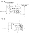
- FIG.3A is a perspective view of the main heat exchanger having an attached-object removal function.
- the main heat exchanger 51 is provided with spray nozzles 521 each of which sprays the sea water to a surface of the heat exchanger tube 511.
- the spray nozzles 521 are provided around the heat exchanger tube 511.
- Each of the spray nozzles 521 is connected to a header 522.
- the sea water pumped by the pump 523 is supplied to the spray nozzles 521 via the header 522 and sprayed through the spray nozzles 521 to the surface of the heat exchanger tubes 511.
- FIG.3B is a perspective view of the main heat exchanger having another type of attached-object removal function.
- the cooling-medium supply line 41, the cooling-medium return line 42 and the pump 47 are not shown.
- This heat exchanger 51' is arranged around the heat exchanger tube 511.
- the heat exchanger 51' includes a perforated header 525 having a plurality of openings 536 formed on one side of the perforated header 525.
- the sea water pumped by the pump 523 is jetted from the openings 526 and the jet flow is supplied around the heat exchanger tube 511.
- the jet flow removes the foreign objects adhered to or accumulated on the heat exchanger tube 511.
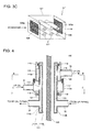
- FIG.3C is a perspective view of the main heat exchanger having yet another type of attached-object removal function.
- the cooling-medium supply line 41, the cooling-medium return line 42 and the pump 47 are not shown.
- the main heat exchanger 51' is configured such that the heat exchanger tube 511 is housed in a casing 527.
- a sea water inlet 528 and a sea water outlet 529 are formed.
- the sea water inlet 528 has a filter 528a to prevent the foreign objects contained in the sea water from entering the casing 527.
- the foreign objects such as marine organisms float in the sea water and the foreign objects attached to the heat exchanger tube 511 of the main heat exchanger 51 leads to a decline of the heat exchange efficiency.
- the marine organisms adhere to the heat exchanger tube 511, the marine organisms grow there and thus, it is unavoidable that the heat exchange efficiency decreases gradually. Therefore, by providing the filter 528a in the sea inlet 528 of the casing 527 housing the main heat exchanger 51, the foreign objects are kept from entering the area around the heat exchanger tube 511, thereby preventing the decline of the heat exchange efficiency.
- a filter 529a may be provided in the sea water outlet 529.
- the filters 528a and 529a are preferably configured interchangeable with each other.
- FIG.4 shows a first configuration example of a swivel structure being applied to the wind turbine generator in relation to the embodiment of the present invention.
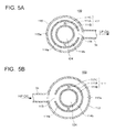
- FIG.5A is a cross-sectional view taken along a line B-B of FIG.4 , showing the first configuration example of the swivel structure of FIG.4 .
- FIG.5B is a cross-sectional view taken along a line C-C of FIG.4 , showing the first configuration example of the swivel structure of FIG.4 .
- the connection part 100 of the swivel structure in the first configuration example has a tubular member 111 which extends in the axial direction of the tower 2 and a first jacket 112 and a second jacket 115 which are provided around the tubular member 111.
- a first flow path 121 in which the high pressure oil flows from the hydraulic pump 8 on the nacelle side to the hydraulic motor 10 on the tower side and a second flow path 122 in which the low pressure oil flows from the hydraulic motor 10 to the hydraulic pump 8 are formed.
- the tubular member 111 has a double-tube structure formed by an outer tube 111A, an inner tube 111B and a partition wall 111C.
- the partition wall 111C divides a circular space formed by the outer tube 111A and the inner 111B in a circumferential direction to create a plurality of arc-shaped flow paths 114a and 114b.
- FIG.4B shows two arc-shaped flow paths 114a and 114b. However, this is not limitative and more than two flow paths may be formed.
- the first jacket is provided around the outer tube 111A of the tubular member 111.
- a circular flow path 112a is formed.
- the circular flow path 112a is in communication with the first HP piping 31 connected to the outer periphery of the first jacket 112.
- the circular flow path 112a is in communication with the arc-shaped flow path 114a via a first communication opening 113.
- the arc-shaped flow path 114a is in communication with the second HP piping 32 connected to the outer periphery of the outer pipe 111A.
- the flow path 121 is formed by the circular flow path 112a and the arc-shaped flow path 114a.
- the high pressure oil supplied from the first HP piping 31 to the first flow path 121 flows through the circular flow path 112a, the first communication opening 113 and the arc-shaped flow path 114a and is supplied to the second HP piping 32.
- the second jacket 115 is provided on an outer circumferential side of the outer tube 111A of the tubular member 111 and closer to the nacelle side than the first jacket 112 is.
- the second jacket 115 is fastened to the first jacket 112 by a bolt 125.
- the arc-shaped flow path 114b of the tubular member 111 is in communication with the second LP piping 33 connected to the outer periphery of the outer tube 111A. Further, the arc-shaped member is in communication with the circular flow path 115a formed between the inner wall surface of the second jacket 115 and the outer wall surface of the outer tube 111A via a second communication opening 116 formed in the outer tube 111A.
- the circular flow path 115a is in communication with the first LP piping 34 connected to the outer periphery of the second jacket 115.
- the second flow path 122 is formed by the arc-shaped flow path 114b and the circular flow path 115a.
- the low pressure oil supplied from the second LP piping 33 to the second flow path 122 flows through the arc-shaped flow path 114b, the second communication opening 116 and the circular flow path 115a and is fed to the first LP piping 34.
- the first jacket 112 and the second jacket 115 are supported on the nacelle side 4.
- the tubular member 111 is supported on the tower side.
- a bearing 118 is provided to maintain liquid tightness therebetween.
- a bearing 119a is provided to maintain liquid tightness therebetween.
- the first jacket 112 and the second jacket 115 are mounted relatively rotatable with respect to the tubular member 111 by means of the bearings 118 and 119.
- the space surrounded by the inner tube 11B of the tubular member 111 may be used as a cable-housing piping 124.
- the cable-housing piping 124 houses a cable 125 extending from the nacelle side to the tower side.
- the cable-housing piping 124 houses the cable 125 such as a power cable used for supplying power to electric utilization equipments arranged in the nacelle 4 such as the hydraulic pump 8, a communication cable used for controlling, a signal cable connected to measuring devices mounted to the nacelle side, and a lightning-protection cable for discharging electric power when the lightning strikes the blade 6B or the nacelle 4.
- the cable 125 is protected against damage.
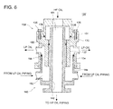
- FIG.6 shows a second configuration example of the swivel structure being applied to the wind turbine generator in relation to the embodiment of the present invention.
- the swivel structure of the second configuration example has a connection part 100'.
- the connection part 100' connects the hydraulic pump 8 housed in the nacelle 4 and the hydraulic motor 10 housed in the tower 2 with use of a first double tube 130 and a second double tube 140.
- the first double tube 130 is fixed to the nacelle 4 and the second double tube 140 is fixed to the tower 2.
- the first double tube 130 and the second double tube 140 are relative rotatable with each other. Now, detailed configurations of the first double tube 130 and the second double tube 140 are explained.
- the first double tube 130 includes an upper part 131 and a lower part 133, which are fastened at a flange portion to each other by bolts 135. Further, a bearing 136 is provided between joint surfaces of the upper part 131 and the lower part 133 to maintain liquid tightness therebetween.
- the upper part 131 has a HP oil inlet which is connected at a top to a discharge side of the hydraulic pump 8 via the first HP piping 31 (see FIG.1 ).
- the lower part 133 includes an inner cylinder part and an outer cylinder part which extend downward from the flange portion fastened to the upper part 131.
- the outer cylindrical part has a LP oil outlet formed on a side surface.
- the LP oil outlet is connected to an intake side of the hydraulic pump 8 via the first LP piping 34 (see FIG.1 ).
- a first inner piping 132 of the first double tube is formed.
- a first outer piping 134 of the first double tube 130 is formed.
- the second double tube 140 includes a second inner piping 142 and a second outer piping 144 formed on the outer periphery of the second inner piping 142.
- the second double tube 140 has a HP oil outlet in a lower part thereof.
- the HP oil outlet is connected to the second HP piping 32 (see FIG.1 ).
- the second double tube 140 has a LP inlet on a side surface.
- the LP oil inlet is connected to the second LP piping 33 (see FIG.1 ).
- the first double tube 130 is rotatably fitted to the second double tube 140.
- first double tube 130 and the second double tube 140 By fitting first double tube 130 and the second double tube 140 in this manner, a first flow path 151 where the high pressure oil flows from the nacelle side to the tower side and a second flow path 152 where the low pressure oil flows from the tower side to the nacelle side 4 are formed.
- an inner bearing 155 is provided between the inner wall surface of the first inner piping 132 and the outer wall surface of the second inner piping 142. Further, between the inner wall surface of the first outer piping 134 and the outer wall surface of the second outer piping 144, an outer bearing 156 is provided.
- the first double tube 130 supported on the nacelle side is rotatably connected to the second double tube 140.
- FIG.7 shows a third configuration example of the swivel structure being applied to the wind turbine generator in relation to an embodiment of the present invention.
- the swivel structure of the third configuration example has a connection part 100".
- the connection part 100" includes a double tube 160 which extends in the axial direction of the tower 2, and a first jacket 164 and a second jacket 166 which are provided to surround the double tube 160.
- a first flow path 171 through which the high pressure oil flow from the hydraulic pump 8 on the nacelle side 4 to the hydraulic motor 10 on the tower side
- a second flow path 172 through which the low pressure oil flows from the hydraulic motor 10 to the hydraulic pump 8.
- the double tube 160 includes an inner tube 160A and an outer tube 160B. Inside the inner tube 160A, an inner flow path is formed. Between the inner tube 160A and the outer tube 160B, an outer flow path is formed.
- the first jacket 164 is arranged on an outer circumferential side of the inner tube 160A.
- a circular flow path 164a is formed by an inner wall surface of the first jacket 164 and an outer wall surface of the inner tube 160A.
- the circular flow path 164a is in communication with the first HP piping 31 connected to the outer periphery of the first jacket 164.
- the circular flow path 164a is in communication with the inner flow path via a first communication opening 161 provided in the inner tube 160A.
- the inner flow path is in communication with the second HP piping 32 connected to a lower part of the inner tube 160A.
- the first flow path 171 is formed by the circular flow path 164a and the inner flow path.
- the high pressure oil supplied from the first HP piping 31 to the first flow path 171 flows through the circular flow path 164a, the first communication opening 161 and the inner flow path and then fed to the second HP piping 32.
- the second jacket 166 is provided on an outer circumferential side of the outer tube 160B and closer to the tower side than the first jacket 164 is.
- the second jacket 166 is fastened to the first jacket 164 by a bolt 175.
- the outer flow path is in communication with the second LP piping 33 connected to the outer periphery of the outer tube 160B and with the circular flow path 166a formed between the inner wall surface of the second jacket 166 and the outer wall surface of the inner tube 160A.
- the circular flow path 166a is in communication with the first LP piping 34 connected to the outer periphery of the second jacket 166.
- the second flow path 172 is formed by the outer flow path and the circular flow path 166a.
- the low pressure oil supplied from the second LP piping 33 to the second flow path 172 flows through the outer flow path and the circular flow path 166a and is fed to the first LP piping 34.
- the first jacket 164 and the second jacket 166 are supported on the nacelle side 4.
- the double tube 160 is supported on the tower side.
- a bearing 176 is provided between the first jacket 164 and the inner tube 160A of the double tube 160 to maintain liquid tightness therebetween.
- a bearing 177 is provided between the second jacket 166 and the outer tube 160B to maintain liquid tightness therebetween.
- the first jacket 164 and the second jacket 166 are mounted relatively rotatable with respect to the double tube 160 by means of the bearings 176 and 177.
- the cooling medium used to cool the operating oil is cooled by heat exchange with sea water around the base portion 2A of the tower 2 and thus, the cooling medium can be cooled by the sea water with higher efficiency than by air-cooling.
- the operating-oil line 30 is divided into the first piping supported on the nacelle side and the second piping supported on the tower side and the first piping and the second piping are arranged relatively rotatable with each other by means of the connection part 100, 100', 100" having the swivel structure. Therefore, even when the nacelle 4 turns, the fluid can communicate smoothly between the first piping on the nacelle side and the second piping on the tower side.
- the operating-oil line 30 extends to the tower side.
- the heat exchange can be performed between the operating oil and the cooling medium in the tower 2. Therefore, it is no longer necessary to extend the cooling-medium line 40 for cooling the operating oil to the nacelle 4.
- the cooling medium is pumped to the nacelle height by the cooling-medium line 40, it is possible to reduce the input of the pump 47 and to downsize the pump 47.
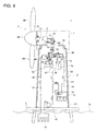
- FIG.8 A first modified example is shown in FIG.8 .
- a cooling-medium branch line 44' is provided.
- the cooling-medium branch line 44' connects the transformer housing cooler 55 and the tower cooler 54 in series.
- the cooling-medium branch line 44' branches from the cooling-medium supply line 41 and joins the cooling-medium return line 42.
- the transformer-housing cooler 55 cools the air inside the transformer housing 21 by heat exchange with the cooling medium flowing in the cooling-medium branch line 44'.
- the cooling medium discharged from the transformer housing cooler 55 is supplied to the tower cooler 54 to cool the air inside the tower 2 by heat exchange with the cooling medium.
- the cooling medium having passed through those coolers returns to the main heat exchanger 51.
- the tower cooler 54 and the transformer-housing cooler 55 may be arranged in this order in the cooling-medium branch line 44'. However, this is not limitative and the coolers may be arranged in any order. In this manner, by providing the cooling-medium line which connects a plurality of heat-generating sources in series, the piping structure can be simplified.
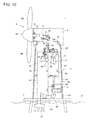
- FIG.9 A second modified example is shown in FIG.9 .
- a plurality of the main heat exchangers are provided.
- FIG.9 shows two main heat exchangers 51a and 51b.
- the cooling-medium return line 42 branches into two lines on an inlet side of the main heat exchangers 51a and 51b, one line being connected to the main heat exchanger 51a and other line being connected to the main heat exchanger 51b.
- Pumps 47a and 47b for circulating the cooling medium are provided respectively in the two lines branched from the cooling-medium return line 42.
- the two lines in which the cooling medium having been cooled in the main heat exchangers 51a and 51b flows join at an outlet side of the main heat exchangers 51a and 51b and the joined line is connected to the cooling-medium supply line 41.
- the number of the main heat exchangers may be determined by a total amount of heat generation from the heat-generating sources which are subjects of cooling.
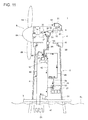
- FIG.10 A third modified example is shown in FIG.10 .
- a cooling-medium tank 49 connected to the cooling-medium line 40 is arranged inside the tower 2 and the cooling-medium tank 49 is sealed off from a space inside the tower 2.
- the cooling-medium tank 49 may be arranged in a lower part of the cooling-medium line.
- FIG.10 shows one cooling-medium tank 49.
- this is not limitative and a plurality of the cooling-medium tanks 49 may be provided, or a combination of the cooling-medium tank 49 and the cooling medium tank 48 of open-type as shown in FIG.1 may be provided.
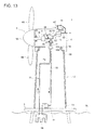
- FIG. 11 shows a general structure of a wind turbine generator in relation to the second embodiment of the present invention.
- the wind turbine generator 1 of the second embodiment is substantially the same as that of the first embodiment, except for configurations of the hydraulic transmission and the operating-oil line 30.
- FIG. 11 mainly the configurations different from the first embodiment are explained and the components already described in the first embodiment are indicated by the same reference numbers in FIG.11 and are not explained further.
- the nacelle swivel mechanism 19 and the yaw driving mechanism 13 are not shown.
- the operating-oil line 30 includes an operating-oil circulation line through which the operating oil circulates between the hydraulic pump 8 and the hydraulic motor 10, and an operating-oil branch line 38 which is connected to the operating-oil circulation line in parallel.
- the operating-oil circulation line includes a high-pressure oil line (HP oil line) 36 which connects an operating-oil outlet side of the hydraulic pump 8 and an operating-oil inlet side of the hydraulic motor 10, and a low-pressure oil line (LP oil line) 37 which connects an operating-oil outlet side of the hydraulic motor 10 and an operating-oil inlet side of the hydraulic pump 8.
- HP oil line high-pressure oil line
- LP oil line low-pressure oil line
- the operating-oil branch line 38 branches from the LP oil line 37 and extends from the nacelle side to the tower side via the connection part having the swivel structure to be connected to the inlet side of the intermediate heat exchanger 52 on the tower side. Further, the operating-oil branch line 38 connected to the outlet side of the intermediate heat exchanger 52 extends from the tower side to the nacelle side via the connection part 100 to join the LP oil line 37.
- the connection part 100 may have the same configuration as the first embodiment.
- a part of the low pressure oil branched from the LP oil line 37 is fed through the operating-oil branch line 38 to the intermediate heat exchanger 52 to cool the part of the low pressure oil by heat exchange with the cooling-medium, and then is returned to the LP oil line 37 through the operating-oil branch line 38.
- the operating-oil line 30 where the flow amount of the operating oil is large can be shorter while reducing the flow amount of the operating oil passing through the connection part 100.
- the piping structure can be simplified.
- the operating-oil branch line 38 branches from the LP oil line 37 and thus, the operating-oil branch line 38 and the connection part 100 can be formed by a piping of low pressure-resistance, resulting in cost reduction.
- the wind turbine generator of the second embodiment may also include a generator cooler 53' to cool the generator 12 by air.
- a duct 81 is provided on the outer periphery of the nacelle 4 to draw in the ambient air.
- the duct 81 has an air inlet and is formed integrally on a wall surface of the nacelle 4.
- the duct 81 may have a fan 82 inside.
- the ambient air drawn in by the duct 81 is led to the inside of the nacelle 4 via an air piping 83.
- a generator cooler 53' is provided in the air piping 83.
- the generator cooler 53' may be configured, for instance, as a cooling jacket formed around the generator 12 to cool the generator 12 by streaming in the outer periphery of the cooling jacket the air drawn in by the duct 81.
- the air after cooling the generator 12 is discharged outside the nacelle through the air piping 83.
- the ambient air drawn in by the duct 81 may be used to cool other heat-generating sources inside the nacelle 4.
- the ambient air may be used to cool the nacelle cooler (not shown) which cools the air inside the nacelle.
- the cool water is used to cool the heat-generating sources inside the tower 2 and the air is used to cool the heat-generating source inside the nacelle 4.
- the heat-generating sources of the wind turbine generator 1 can be cooled efficiently.
- FIG.12 shows a general structure of a wind turbine generator in relation to the third embodiment of the present invention.
- the wind turbine generator 1 of the third embodiment is substantially the same as that of the first embodiment, except for configurations of the hydraulic transmission and the operating-oil line 30.
- FIG. 12 shows the nacelle swivel mechanism 19 and the yaw deriving mechanism 13.
- the hydraulic motor 10 and the generator 12 are arranged in the nacelle 4 and the intermediate heat exchanger 52 is arranged in the nacelle 4 as well.
- the operating-oil line 30 includes an operating-oil circulation line through which the operating oil circulates between the hydraulic pump 8 and the hydraulic motor 10, and an operating-oil branch line 38' which is connected to the operating-oil circulation line in parallel. Both of the operating-oil circulation line and the operating-oil branch line 38' are arranged in the nacelle 4.
- the operating-oil circulation line includes a high-pressure oil line (HP oil line) 36 which connects the operating-oil outlet side of the hydraulic pump 8 and the operating-oil inlet side of the hydraulic motor 10, and a low-pressure oil line (LP oil line) 37 which connects the operating-oil outlet side of the hydraulic motor 10 and the operating-oil inlet side of the hydraulic pump 8.
- HP oil line high-pressure oil line
- LP oil line low-pressure oil line
- the operating-oil branch line 38' branches from the LP oil line 37 and is connected to the inlet side of the intermediate heat exchanger 52 arranged in the nacelle 4. Further, the operating-oil branch line 38' connected to the outlet side of the intermediate heat exchanger 52 joins the LP oil line 37.
- the cooling-medium line 40 includes a cooling-medium supply line 41 which is provided between the main heat exchanger 51 and the intermediate heat exchanger 52 via the connection part 100 having the swivel structure, and a cooling-medium return line 42 which is provided between the intermediate heat exchanger 52 and the main heat exchanger 51 via the connection part 100 in the same manner. Further, the connection part 100 may have the same configuration as the first embodiment.
- the cooling medium having been cooled by the sea water in the main heat exchanger 51 is supplied to the intermediate heat exchanger 52 through the cooling-medium supply line 41 and cools the operating oil by heat exchange in the intermediate heat exchanger 52 and then returns to the main heat exchanger 51 through the cooling-medium return line 42.
- connection part 100 can be formed by a piping of low pressure-resistance, resulting in cost reduction.
- the cooling-medium line 40 may include a cooling-medium branch line 43' which branches from a nacelle side of the cooling-medium supply line 41 and joins a nacelle side of the cooling-medium return line 42.
- the generator cooler 53 may be provided to cool the generator 12.
- the generator cooler 53 may be configured, for instance, as a cooling jacket formed around the generator 12. In the generator cooler 53, the generator 12 is cooled by heat exchange with the cooling medium supplied from the cooling-medium branch line 43'.
- FIG. 13 shows a general structure of a wind turbine generator in relation to the fourth embodiment of the present invention.
- the wind turbine generator 1 of the forth embodiment is not provided with the cooling-medium line 40 and the operating oil of the hydraulic transmission is cooled directly by the sea water.
- the wind turbine generator 1 of the fourth embodiment is substantially the same as that of the first embodiment, except for configurations of the hydraulic transmission, the operating-oil line 30 and the cooling-medium line 40.
- FIG.13 shows the configurations different from the first embodiment and the components already described in the first embodiment are indicated by the same reference numbers in FIG.13 and are not explained further.
- the nacelle swivel mechanism 19 and the yaw driving mechanism 13 are not shown.
- the operating-oil line 30 includes an operating-oil circulation line through which the operating oil circulates between the hydraulic pump 8 and the hydraulic motor 10, and an operating-oil branch line 70 which is connected to the operating-oil circulation line in parallel. Both of the operating-oil circulation line and the operating-oil branch line 70 are arranged in the nacelle 4.
- the operating-oil circulation line includes a HP oil line 36 which connects the operating-oil outlet side of the hydraulic pump 8 and the operating-oil inlet side of the hydraulic motor 10, and a LP oil line 37 which connects the operating-oil outlet side of the hydraulic motor 10 and the operating-oil inlet side of the hydraulic pump 8.
- the operating-oil branch line 70 includes the first piping 71, 74 supported own the nacelle side and a second piping 72, 73 supported on the tower side.
- the operating-oil branch line 70 is preferably arranged in parallel to the LP oil line 37.
- a pump is provided to stream the operating oil in the operating-oil branch line 70.
- the first piping 71 and the second piping 72 are connected relatively rotatable by means of the connection part 100 having the swivel structure.
- the first piping 73 and the second piping 74 are connected relatively rotatable by means of the connection part 100.
- the connection part 100 has the same configuration as the first embodiment.
- the connection part 100 may have the same configuration as the first embodiment.
- the operating oil which branched from the LP oil line 37 is introduced through the first piping 71, the connection part 100 and the second piping 72 to the main heat exchanger 58 in this order.
- the cooling medium is cooled by heat exchange with the sea water.
- the cooling medium discharged from the main heat exchanger 58 is returned through the second piping 73, the connection part 100 and the first piping 74 to the LP oil line 37 in this order.
- the operating oil is cooled by heat exchange with cool water source which is one of sea water, lake water, river water and groundwater around the base portion of the tower. Therefore, the operating oil can be cooled by the cool water source with higher efficiency than by air-cooling.
- cool water source which is one of sea water, lake water, river water and groundwater around the base portion of the tower. Therefore, the operating oil can be cooled by the cool water source with higher efficiency than by air-cooling.
- one of the operating-oil circulation line and the operating-oil branch line 70 is divided into the first piping 71, 74 supported on the nacelle side and the second piping 72, 73 supported on the tower side and the first piping 71, 74 and the second piping 72, 73 are arranged relatively rotatable with each other by means of the connection part 100, 100', 100" having the swivel structure. Therefore, even when the nacelle 4 turns, the fluid can communicate smoothly between the first piping 71, 74 on the nacelle side and the second piping
- the wind turbine generator 1 of the fourth embodiment may also include the generator cooler 53' to cool the generator 12 by air.
- the duct 81 is provided on the outer periphery of the nacelle 4 to draw in the ambient air.
- the ambient air drawn in by the duct 81 is led to the inside of the nacelle 4 via the air piping 83.
- the generator cooler 53' is provided in the air piping 83.
- the generator cooler 53' may be configured, for instance, as a cooling jacket formed around the generator 12 to cool the generator 12 by streaming in the outer periphery of the cooling jacket the ambient air drawn in by the duct 81.
- the air after cooling the generator 12 is discharged outside the nacelle through the air piping 83.
- the ambient air drawn in by the duct 81 may be used to cool other heat-generating sources inside the nacelle 4.
- the ambient air may be used to cool the nacelle cooler (not shown) which cools the air inside the nacelle 4.
- the cool water is used to cool the heat-generating sources inside the tower 2 and the air is used to cool the heat-generating source inside the nacelle 4.
- the heat-generating sources of the wind turbine generator 1 can be cooled efficiently.
- the wind turbine generator 1 is described as a specific example of the power generating apparatus of renewable energy type.
- the present invention is not limited to this and is also applicable to other types of power generating apparatuses of renewable energy type.
- the present invention may be applied to a power generating apparatus which uses one of tidal current, ocean current and river current to generate power and the tower of which extends upward in the vertical direction from the base portion to the tip portion in or under the sea and the main shaft of which rotates upon receiving one of tidal current, ocean current and river current on the blade.
Landscapes
- Engineering & Computer Science (AREA)
- Mechanical Engineering (AREA)
- General Engineering & Computer Science (AREA)
- Chemical & Material Sciences (AREA)
- Life Sciences & Earth Sciences (AREA)
- Sustainable Development (AREA)
- Sustainable Energy (AREA)
- Combustion & Propulsion (AREA)
- Thermal Sciences (AREA)
- Physics & Mathematics (AREA)
- Ocean & Marine Engineering (AREA)
- Wind Motors (AREA)
- Heat-Exchange Devices With Radiators And Conduit Assemblies (AREA)
Abstract
Description
- The present invention relates to a power generating apparatus of renewable energy type which transmits rotation energy of a rotor from a renewable energy source to a generator, particularly a power generating apparatus of a renewable energy type having a function of cooling a hydraulic transmission.
- From the perspective of preserving the global environment, power generating apparatuses of a renewable energy type such as a wind turbine generator using wind power and a tidal generator using tidal current, river current or ocean current energy are becoming popular. To improve power generation efficiency, it is desired to increase the size of the power generating apparatus of the renewable energy type. Particularly, wind turbine generators installed offshore are expensive to construct in comparison to those installed onshore and thus, it is desired to improve power generation efficiency by increasing the size of the wind turbine generator so as to improve profitability.
- In the case of the power generating apparatus of renewable energy type equipped with a mechanical gearbox, weight and cost of the gearbox tends to increase with increase in size of the apparatus. Thus, a power generating apparatus equipped with a hydraulic transmission having a hydraulic pump and a hydraulic motor, instead of the mechanical gearbox, is becoming popular.
- As the power generating apparatus of renewable energy type equipped with the hydraulic transmission, a wind turbine generator having a hydraulic pump, a hydraulic motor and a generator in a nacelle is introduced in
Patent Literature 1, for example, In the wind turbine generator, a rotation energy of a rotor is transmitted to the generator via the hydraulic transmission (seeFig.7 of Patent Literature 1).
A wind turbine generator disclosed inPatent Literature 2 has a hydraulic pump installed in the nacelle, and a hydraulic motor and a generator installed at a bottom of a tower and the hydraulic pump and the hydraulic motor are connected by a piping. - Meanwhile, with increased output of the generator produced by the larger wind turbine generator, heat loss from the generator increases. In the wind turbine generator having the hydraulic transmission formed by the hydraulic pump and the hydraulic motor, in addition to the heat loss from the generator, there is heat loss from the hydraulic transmission. Thus, a wind turbine generator having a function of cooling a heat-producing component such as the generator and the hydraulic transmission is desired.
- In view of this,
Patent Literature 3 proposes a wind turbine generator having a cooling system for cooling a converter, a transformer and a control unit. The cooling system includes a plurality of heat exchangers installed around a tower. In the heat exchangers, a cooling medium having cooled the converter, the converter, the transformer and the control unit is cooled by heat exchange with atmospheric air.
Patent Literature 4 discloses a cooling device for a wind turbine generator. The cooling device has a heat exchanger to cool a plurality of devices such as a converter, a transformer, a bearing box and a generator. Cooling water cools the devices and then is cooled by the heat exchanger installed on an outer wall of a tower and a nacelle. -
- [Patent Literature 1]
WO 2007/053036 - [Patent Literature 2]
WO 2009/064192 - [Patent Literature 3]
EP 1798414A - [Patent Literature 4]
EP 2007184A - Normally, a power generating apparatus of renewable energy type, which generates electric power from renewable energy such as wind power, tidal current, river current and ocean current, is installed where there is significant temperature change of a surrounding environment such as temperature of ambient air, water and so on. This changes a temperature of an operating oil of the hydraulic transmission. The viscosity of the operating oil changes in accordance with the temperature change. At a low temperature, the viscosity of the operating oil becomes high, resulting in significant energy loss in the hydraulic transmission. At a high temperature, the viscosity of the operating oil decreases, resulting in accelerating degradation of the operating oil. This leads to a decline of the lubricating property, wear of the sliding part and leaking of the operating oil. Therefore, in the power generating apparatus installed with the hydraulic transmission, it is desired to keep the operating oil at an appropriate temperature. However, such technique is not disclosed in the prior art such as
Patent Literatures - In the cooling system disclosed in
Patent Literatures
In view of the above issues, it is an object of the present invention is to provide a power generating apparatus of renewable energy type installed with a cooling mechanism which is capable of efficiently cooling the operating oil of the hydraulic transmission. - As one aspect of the present invention, a power generating apparatus of renewable energy type which generates power from renewable energy, may include, but is not limited to: a tower; a nacelle which is supported rotatably by a tip portion of the tower; a main shaft which is housed in the nacelle and rotates with a blade; a hydraulic pump which is housed in the nacelle and is driven by rotation of the main shaft; a hydraulic motor which is driven by operating oil supplied from the hydraulic pump; a generator which is coupled to the hydraulic motor; an operating-oil line which is provided between the hydraulic pump and the hydraulic motor and through which the operating oil circulates; a cooling-medium line through which cooling medium for cooling the operating oil circulates via an intermediate heat exchanger; and a main heat exchanger which cools the cooling medium by heat exchange with cool water source which is one of sea water, lake water, river water and groundwater around a base portion of the tower, and one of the operating-oil line and the cooling-medium line may include, but is not limited to: a first piping which is supported on a nacelle side; a second piping which is supported on a tower side; and a connection part which connects the first piping and the second piping so that the first piping and the second piping are relatively rotatable.
- According to the aspect of the present invention, the cooling medium used to cool the operating oil, is cooled by heat exchange with the cool water source which is one of sea water, lake water, river water and groundwater around the base portion of the tower and thus, the cooling medium can be cooled by the cool water with high efficiency.
Further, one of the operating-oil line and the cooling-medium line is divided into the first piping supported on the nacelle side and the second piping supported on the tower side and the first piping and the second piping are arranged relatively rotatable with each other by means of the connection part having the swivel structure. Therefore, even when the nacelle turns, the fluid can communicate smoothly between the first piping on the nacelle side and the second piping on the tower side - In the above power generating apparatus of renewable energy type, the hydraulic motor may be provided between the tip portion and the base portion of the tower, the operating-oil line may extend between the hydraulic pump arranged in the nacelle and the hydraulic motor arranged in the tower, the operating-oil line may include the first piping, the second piping and the connection part, and the first piping may be connected to the hydraulic pump and the second piping is connected to the hydraulic motor.
- In this manner, by arranging the hydraulic motor between the tip portion and the base portion of the tower, the operating-oil line extends to the tower side. Thus, the heat exchange can be performed between the operating oil and the cooling medium in the tower. Therefore, it is no longer necessary to extend the cooling-medium line for cooling the operating oil to the nacelle. Hence, in comparison to the case in which the cooling medium is pumped to the nacelle height by the cooling-medium line, it is possible to reduce the input of the pump and to downsize the pump.
- Alternatively, in the above power generating apparatus of the renewable energy type, the hydraulic motor may be supported on the nacelle side and the intermediate heat exchanger is supported on the tower side, the operating-oil line may include an operating-oil circulation line through which the operating oil circulates between the hydraulic pump and the hydraulic motor, and an operating-oil branch line which branches from a low-pressure side of the operating-oil circulation line and through which the operating-oil line returns to the operating-oil circulation line via the intermediate heat exchanger, the operating-oil branch line may include the first piping, the second piping and the connection part, and the first piping may be connected to the operating-oil circulation line and the second piping is connected to the intermediate heat exchanger.
- In this manner, by supporting the hydraulic motor on the nacelle side and connecting the operating-oil branch line branching from the low-pressure side of the operating-oil circulation line to the intermediate heat exchanger on the tower side, the operating-oil circulation line where the flow amount of the operating oil is large can be shorter while reducing the flow amount of the operating oil passing through the connection part. By this, the piping structure can be simplified. Further, the operating-oil branch line branches from the low pressure side of the operating-oil circulation line and thus, the operating-oil branch line and the
connection part 100 can be formed by a piping of low pressure-resistance, resulting in cost reduction. - Alternatively, in the above power generating apparatus of renewable energy type, the hydraulic motor and the generator may be arranged in the nacelle and the intermediate heat exchanger is supported on the nacelle side, the cooling-medium line may include the first piping, the second piping and the connection part, and the first piping may be connected to an intermediate heat exchanger side and the second piping is connected to a main heat exchanger side.
In this manner, by arranging the hydraulic motor and the generator in the nacelle and by connecting the cooling-medium line via the connection part to the intermediate heat exchanger supported on the nacelle side, the connection part can be formed by a piping of low pressure-resistance, resulting in cost reduction. - The above power generating apparatus of renewable energy type may include, but is not limited to: at least one first flow path in which fluid flows from the nacelle side to the tower side; at least one second flow path in which fluid flows from the tower side to the nacelle side; a tubular member in which the at least one first flow and the at least one second flow path are formed; a first jacket which is provided around the tubular member and which includes a circular flow path which communicates with the first piping through a first communication opening; and a second jacket which is provided around the tubular member and which includes a circular flow path which communicates with the second piping through a second communication opening, and the first jacket and the second jacket are fixed to the tubular member via a bearing to be freely rotatable relative to the tubular member.
- In the above power generating apparatus of renewable energy type, the fluid flowing from the nacelle side to the tower side enters the first flow path formed in the tubular member via the first communication opening from the circular flow path of the first jacket connected to the first piping so as to flow from the first flow path to the second piping. Meanwhile, the fluid flowing from the tower side to the nacelle side, enters the second flow path formed in the tubular member via the second communication opening from the circular path of the second jacket connected to the second piping so as to flow from the second flow path to the first piping. The first jacket and the second jacket are arranged relatively rotatable with respect to the tubular member via the bearing and thus, the relative rotation between the piping on the nacelle side and the piping on the tower side while securing the flow of the fluid flowing from the nacelle side to the tower side and the flow of the fluid flowing from the tower side to the nacelle side and the flow of the fluid
- In the above case, the tubular member may have a cable-housing piping on an inner side of the first and second flow paths, the cable-housing piping housing a cable extending from the nacelle side to the tower side.
By this, even when the nacelle turns, the cable is housed in the cable-housing piping formed in the tubular member and thus, protected against damage - The above power generating apparatus of renewable energy type may include, but is not limited to: a water supply source which supplies water to the cooling-medium line; and a pump which circulates cooling-medium in the cooling-medium line, the cooling-medium being formed by adding antifreeze to the water.
In this manner, by providing the water supply source which supplied water to the cooling-medium line and the pump which circulates the cooling-medium in the cooling-medium line, a flow rate of the circulating cooling medium can be regulated, for instance, in accordance with a temperature change of the ambient air or the like and the operating oil can be maintained at a constant temperature. Further, by using the cooling medium being formed by adding antifreeze to the water, even when the ambient air becomes not greater than a freezing temperature of the water, freezing of the cooling-medium is prevented and thus, the smooth operation of the cooling mechanism can be achieved. - In the above case, the water supply source may be a cooling-medium tank which stores the cooling medium, and the cooling-medium tank may be arranged in an upper part of the tower and open to a space inside the tower.
By arranging the cooling-medium tank in the upper part of the tower and allowing the cooling medium tank to be open to the space inside the tower, it is possible to maintain sufficient water pressure in a lower part of the cooling-medium line and thus to positively supply the cooling medium to the cooling devices connected to the cooling-medium line. With use of siphon effect, it is possible to reduce the input of the pump and to downsize the pump. - Further, in the above case, the water supply source may be a cooling-medium tank which stores the cooling medium, and the cooling-medium tank may be arranged in an upper part of the tower and is sealed off from a space inside the tower.
In this manner, by arranging the cooling-medium tank inside the tower and sealing the cooling-medium tank from the space inside the tower, the position where the cooling-medium tank is arranged is no longer restricted. For instance, the cooling-medium tank may be arranged in a lower part of the cooling-medium line. - The above power generating apparatus of renewable energy type may further include: a casing which houses the main heat exchanger and has an inlet for the cool water source; and a filter which is provided at the inlet for the cool water source of the casing to prevent foreign objects contained in the cool water source from entering the casing.
As described above, the cool water source is one of sea water, lake water, river water and groundwater and the foreign objects such as marine organisms float are included in such water. The foreign objects attached to the heat exchanger tube of the main heat exchanger leads to a decline of the heat exchange efficiency. Especially, attached organisms grow on the heat exchanger tube and thus, it is unavoidable that the heat exchange efficiency decreases gradually. In view of this, by providing the filter in a water inlet of the casing housing the main heat exchanger, the foreign objects are kept from entering the area around the heat exchanger tube, thereby preventing the decline of the heat exchange efficiency. - In the above power generating apparatus of renewable energy type, the main heat exchanger may be arranged on a base on which the tower is installed.
By this, the structure of the main heat exchanger on the cool water side can be simplified. - In such case, a flow-rate regulating structure may be provided around the heat exchanger tube of the heat exchanger to regulate a flow rate of the cool water source, and a distance between the flow-rate regulating structure and the heat exchanger tube may have an upper limit which is set based on a distance at which a set heat transfer coefficient is achieved in the heat exchanger tube, and a lower limit which is set based on a distance at which foreign objects adhered to the heat exchanger tube is detached.
The flow-rate regulating structure is provided around the heat exchanger tube so as to achieve an appropriate heat transfer coefficient as the flow rate of the cool water source flowing around the heat exchanger tube affects the heat transfer coefficient of the heat exchanger tube. Therefore, by setting the upper limit of the distance between the flow-rate regulating structure and the heat exchanger tube based on a distance at which a set heat transfer coefficient is achieved in the heat exchanger tube, it is possible to achieve heat transfer coefficient appropriate for cooling the cooling medium. Further, by setting the lower limit of the distance based on a distance at which foreign objects adhered to the heat exchanger tube is detached, it is possible to prevent the foreign objects from accumulating on the heat exchanger tube. - In the above case, a spray nozzle which sprays the cool water source to a surface of a heat exchanger tube of the main heat exchanger, may be provided.
By this, even when the foreign objects contained in the cool water source adhere to the heat exchanger tube of the main heat exchanger, the cool water source jetted from the spray nuzzles can remove the foreign objects from the heat exchanger tube. In this manner, the foreign objects are physically removed by means of the spray nozzles. Thus, it is no longer necessary to apply paint containing harmful ingredients on the heat exchanger or to inject chorine. It is now possible to prevent the foreign objects from adhering to or accumulating on the heat exchanger tube and also to minimize the impact on the environment. - Alternatively, in the above case, the heat exchanger may be a multitube heat exchanger having a plurality of heat exchanger tubes.
In this manner, the use of the multitube heat exchanger as the heat exchanger achieves a cheap cost and increases a heat-transfer area, hence keeping the high heat exchanger efficiency in the heat exchanger. The heat exchanger here refers to the main heat exchanger or the intermediate heat exchanger. - Further, the power generating apparatus of renewable energy type may be a wind turbine generator, the tower may extend upward in a vertical direction from the base portion toward the tip portion, and the main shaft may rotate upon receiving wind on the blade.
- The above power generating apparatus of renewable energy type may further include a generator cooler which is housed in the nacelle and which cools the generator by air drawn in from a periphery of the nacelle.
In this manner, by combining the cooling of the cooling medium by cool water and the cooling of the generator by air, it is possible to attain an effective cooling mechanism for the power generating apparatus of renewable energy type. - As another aspect of the present invention, a power generating apparatus of renewable energy type which generates power from renewable energy, may include but is not limited to: a tower; a nacelle which is supported rotatably at a tip portion of the tower; a main shaft which is housed in the nacelle and rotates with a blade; a hydraulic pump which is housed in the nacelle and is driven by rotation of the main shaft; a hydraulic motor which is driven by operating oil supplied from the hydraulic pump; a generator which is coupled to the hydraulic motor; an operating-oil circulation line which is provided between the hydraulic pump and the hydraulic motor and through which the operating oil circulates; a main heat exchanger which cools the operating oil by heat exchange with cool water source which is one of sea water, lake water, river water and groundwater around a base portion of the tower; and an operating-oil branch line which branches from the operating-oil circulation line, and
one of the operating oil circulation line and the operating-oil branch line may include, but is not limited to: a first piping which is supported on a nacelle side; a second piping which is supported on a tower side; and a connection part which connects the first piping and the second piping so that the first piping and the second piping are relatively rotatable. - According to the other aspect of the present invention as described, the operating oil is cooled by heat exchange with cool water source which is one of sea water, lake water, river water and groundwater around the base portion of the tower. Therefore, the operating oil can be cooled by the cool water source with high efficiency.
Further, one of the operating-oil circulation line and the operating-oil branch line is divided into the first piping supported on the nacelle side and the second piping supported on the tower side, and the first piping and the second piping are arranged relatively rotatable with each other by means of the connection part having the swivel structure. Therefore, even when the nacelle turns, the fluid can communicate smoothly between the first piping on the nacelle side and the second piping on the tower side. - In such case, the power generating apparatus of renewable energy type may be provided with a generator cooler which is housed in the nacelle and which cools the generator by air drawn in from a periphery of the nacelle.
In this manner, by combining the cooling of the operating oil by cool water and the cooling of the generator by air, it is possible to attain an effective cooling mechanism for the power generating apparatus of renewable energy type. - In the one aspect of the present invention, the cooling medium used to cool the operating oil, is cooled by heat exchange with the cool water source which is one of sea water, lake water, river water and groundwater around the base portion of the tower and thus, the cooling medium can be cooled by cool water with high efficiency.
Further, one of the operating-oil line and the cooling-medium line is divided into the first piping supported on the nacelle side and the second piping supported on the tower side and the first piping and the second piping are arranged relatively rotatable with each other by means of the connection part having the swivel structure. Therefore, even when the nacelle turns, the fluid can communicate smoothly between the first piping on the nacelle side and the second piping on the tower side. - In the other aspect of the present invention, the operating oil is cooled by heat exchange with cool water source which is one of sea water, lake water, river water and groundwater around the base portion of the tower. Therefore, the operating oil can be cooled by the cool water source with high efficiency.
Further, one of the operating-oil circulation line and the operating-oil branch line is divided into the first piping supported on the nacelle side and the second piping supported on the tower side, and the first piping and the second piping are arranged relatively rotatable with each other by means of the connection part having the swivel structure. Therefore, even when the nacelle turns, the fluid can communicate smoothly between the first piping on the nacelle side and the second piping on the tower side. -
- [
FIG.1] FIG.1 shows a general structure of a wind turbine generator in relation to a first embodiment of the present invention. - [
FIG.2A] FIG.2A is a side view of a main heat exchanger ofFIG.1 as a specific configuration example. - [
FIG.2B] FIG.2B is a cross-sectional view of the main heat exchanger taken along a line A-A ofFIG.2A . - [
FIG.2C] FIG.2C is a perspective of the main heat exchanger shown inFIG.2A . - [
FIG.3A] FIG.3A is a perspective of the main heat exchanger having an attached-object removal function. - [
FIG.3B] FIG.3B is a perspective view of the main heat exchanger having another type of attached-object removal function. - [
FIG.3C] FIG.3C is a perspective view of the main heat exchanger having yet another type of attached-object removal function. - [
FIG.4] FIG.4 shows a first configuration example of a swivel structure being applied to the wind turbine generator in relation to an embodiment of the present invention. - [
FIG.5A] FIG.5A is a cross-sectional view taken along a line B-B ofFIG.4 , showing the first configuration example of the swivel structure ofFIG.4 . - [
FIG.5B] FIG.5B is a cross-sectional view taken along a line C-C ofFIG.4 , showing the first configuration example of the swivel structure ofFIG.4 . - [
FIG.6] FIG.6 shows a second configuration example of the swivel structure being applied to the wind turbine generator in relation to an embodiment of the present invention. - [
FIG.7] FIG.7 shows a third configuration example of the swivel structure being applied to the wind turbine generator in relation to an embodiment of the present invention. - [
FIG.8] FIG.8 is a general view showing a first modified example of the wind turbine generator ofFIG.1 . - [
FIG.9] FIG.9 is a general view showing a second modified example of the wind turbine generator ofFIG.1 . - [
FIG.10] FIG.10 is a general view showing a third modified example of the wind turbine generator ofFIG.1 . - [
FIG.11] FIG.11 shows a general structure of a wind turbine generator in relation to a second embodiment of the present invention. - [
FIG. 12] FIG. 12 shows a general structure of a wind turbine generator in relation to a third embodiment of the present invention. - [
FIG. 13] FIG. 13 shows a general structure of a wind turbine generator in relation to a fourth embodiment of the present invention. - A preferred embodiment of the present invention will now be described in detail with reference to the accompanying drawings. It is intended, however, that unless particularly specified, dimensions, materials, shape, its relative positions and the like shall be interpreted as illustrative only and not limitative of the scope of the present invention.
- In a first embodiment, a wind turbine generator is described as an example of a power generating apparatus of renewable energy type.
FIG.1 shows a general structure of the wind turbine generator in relation to the first embodiment.
As shown inFIG.1 , thewind turbine generator 1 is mainly formed by atower 2, anacelle 4 provided at atip portion 2B of thetower 2, arotor 6 being rotated by wind, ahydraulic pump 8, ahydraulic motor 10 and agenerator 12 being coupled to thehydraulic motor 10.
Thewind turbine generator 1 shown inFIG.1 is an offshore wind turbine generator installed at a sea level SL. However, this is not limitative and thewind turbine generator 1 may be installed on shore where cool water source is available nearby. - The
tower 2 is installed upright on abase 3 which is arranged at a height near the seal level. Thetower 2 extends upward from abase portion 2A facing thebase 3 to thetip portion 2B in a vertical direction. Thenacelle 4 is provided on thetip portion 2B of thetower 2. - The
nacelle 4 has abaseplate 16 which is rotatably supported by thetip portion 2B of thetower 2 via anacelle bearing 18. Specifically, thenacelle baseplate 16 is fixed to aninner race 18A of thenacelle bearing 18 and thetip portion 2B of the tower is fixed to anouter race 18B of thenacelle bearing 18.
Anacelle swivel mechanism 19 is installed to thenacelle baseplate 16 and ayaw driving mechanism 13 is mounted on thenacelle baseplate 16. By means of thenacelle swivel mechanism 19 and theyaw driving mechanism 13, thenacelle baseplate 16 swivel with respect to thetip portion 2B of thetower 2. - The
nacelle swivel mechanism 19 may be formed, for instance, by aninternal gear 19B provided on an inner periphery of the tip portion 28 of thetower 2 and agear 19A meshing with theinternal gear 19B.
Theyaw driving mechanism 13 may be, for instance, directly coupled to a shaft of thegear 19A or formed by a reducer connected to thegear 19A via a pinion, a clutch, a yaw motor, an electromagnetic break, and a housing which houses these components.
With the above structure, when the electromagnetic break is turned ON in a state that the clutch is connected, a driving force of the yaw motor is transmitted to thegear 19A via the reducer and then thegear 19A revolves while meshing with theinternal gear 19B. By this, thenacelle 4 turns with respect to thetower 2 in a yaw direction. - The
nacelle 4 houses amain shaft 14 and thehydraulic pump 8 connected to themain shaft 14. Themain shaft 14 is rotatably supported by the nacelle via amain shaft bearing 15.
Therotor 6 includes ahub 6A and a plurality ofblades 6B extending radially from thehub 6A. Thehub 6A of therotor 6 is coupled to themain shaft 14. Thus, when therotor 6 rotates upon receiving the wind, the main shaft rotates with thehub 6A. Then, the rotation of themain shaft 14 is inputted to thehydraulic pump 8 and thehydraulic pump 8 generates operating oil of high pressure (high pressure oil). - The
hydraulic motor 10 is arranged in a space inside the tower between thetip portion 2B and thebase portion 2A of the tower. Preferably, thehydraulic motor 10 is arranged at a position closer to thetip portion 2B than to thebase portion 2A, i.e. on an upper side of the tower. Meanwhile, thehydraulic motor 10 is supported on the tower side. For instance, thehydraulic motor 10 may be mounted on a floor, a board, a shelf or the like which is fixed to thetower 2.
Thehydraulic motor 10 is driven by the high pressure oil supplied from thehydraulic pump 8 arranged in thenacelle 4.
Thegenerator 12 connected to thehydraulic motor 10 via an output shaft, is also supported on the tower side. Thegenerator 12 may be also mounted on a floor, a board, a shelf or the like.
A relative position between thehydraulic motor 10 and thegenerator 12 may be horizontal to each other or vertical to each other as shown inFIG.1 . - An operating-
oil line 30 is provided between thehydraulic pump 8 and thehydraulic motor 10 and the operating oil flows in the operating-oil line 30.
The operating-oil line 30 includes a high-pressure side piping through which the high pressure oil is supplied from thehydraulic pump 8 to thehydraulic motor 10, and a low-pressure side piping through which the operating oil of low pressure (low pressure oil) is supplied from thehydraulic motor 10 to thehydraulic pump 8.
The high-pressure side piping is formed by a first high-pressure side piping 31 (first HP piping) which is supported on the nacelle side, a second high-pressure side piping 32 (second HP piping) which is supported on the tower side. Between the first HP piping 31 and the second HP piping 32, aconnection part 100 is provided. Theconnection part 100 has a swivel structure and the first HP piping 31 and the second HP piping 32 are connected by theconnection part 100 so as to be relatively rotatable.
The low-pressure side piping is formed by a first low-pressure side piping 34 (first LP piping) which is supported on the nacelle side, a second low-pressure side piping 33 (second LP piping) which is supported on the tower side. Between the first LP piping 34 and the second LP piping 33, theconnection part 100 is provided. The first LP piping 34 and the second LP piping 33 are connected by theconnection part 100 so as to be relatively rotatable.
Theconnection part 100 having the swivel structure is arranged at a rotation center of thenacelle 4. The configuration of theconnection part 100 is described later in detail. - The operating-
oil line 30 also includes an operating-oil branch line 35 through which at least a part of the low pressure oil from the second LP piping 33 is fed to anintermediate heat exchanger 52 and the low pressure oil discharge from theintermediate heat exchanger 52 returns to the second LP piping 33. The operating oil branched from the operating-oil branch line 35 is cooled by heat exchange with cooling-medium in theintermediate heat exchanger 52 and returns to the second LP piping 33. - The
hydraulic pump 8 is driven by themain shaft 14 and generates the high pressure oil. The high pressure oil is supplied to thehydraulic motor 10 via the high-pressure side piping to drive the hydraulic motor by the high pressure oil. Meanwhile, thegenerator 12 coupled to thehydraulic motor 10 is driven and thegenerator 12 generates electric power. The low pressure oil discharged from thehydraulic motor 10 is supplied to thehydraulic pump 8 via the low-pressure side piping. The low pressure oil is pressurized again by thehydraulic pump 8 to generate the high pressure oil and the high pressure oil is fed to thehydraulic motor 10. - In the embodiment, a cooling mechanism is also provided to cool the operating oil flowing in the operating-
oil line 30. The cooling mechanism may be used for a variety of cooling devices for cooling a heat-generating source in thenacelle 4 or in thetower 2. The cooling mechanism is now described in detail.
The cooling mechanism mainly includes amain heat exchanger 51, theintermediate heat exchanger 52 and a cooling-medium line 40. - The
main heat exchanger 51 cools the cooling medium by heat exchange with cool water source which is one of sea water, lake water, river water and groundwater around thebase portion 2A of thetower 2. In the offshore wind turbine generator shown inFIG.1 , themain heat exchanger 51 is installed to thebase 3 of thetower 2 and is configured to cool the cooling medium by heat exchange with the sea water. This simplifies a piping structure of the cool water side of themain heat exchanger 51.
Theintermediate heat exchanger 52 is arranged in thetower 2 and cools the operating oil by heat exchange with the cooling medium. - The cooling-
medium line 40 is arranged in thetower 2 and is a closed loop through which the cooling medium for cooling the operating oil circulates. As the cooling medium, water, oil, water to which antifreeze is added, or the like may be used. Specifically, the cooling-medium line 40 includes a cooling-medium supply line 41 which is provided between themain heat exchanger 51 and theintermediate heat exchanger 52 and through which the cooling medium having been cooled by the sea water in themain heat exchanger 51 is supplied to theintermediate heat exchanger 52, and a cooling-medium return line 42 which is provided between theintermediate heat exchanger 52 and themain heat exchanger 51 and through which the cooling medium after cooling the operating oil in theintermediate heat exchanger 52 returns to themain heat exchanger 51. - The cooling-
medium line 40 includes a cooling-medium branch line 43 which branches from the cooling-medium supply line 41 and through which the cooling medium returns to the cooling-medium return line 42. In the cooling-medium branch line 43, a generator cooler 53 is provided to cool thegenerator 12.
The generator cooler 53 may be configured, for instance, as a cooling jacket formed around thegenerator 12. The generator cooler 53 cools thegenerator 12 by heat exchange with the cooling medium supplied from the cooling-medium branch line 43. - The cooling-
medium line 40 includes another cooling-medium branch line 44 which branches from the cooling-medium supply line 41 and joins the cooling-medium return line 42 in a manner similar to the cooling-medium branch line 43. In the cooling-medium branch line 44, atower cooler 54 is provided to cool the space inside thetower 2.
Thetower cooler 54 is configured as a heat exchanger installed with a fan and a group of heat exchanger tubes. In thetower cooler 54, the air drawn in (or forced out) by the fan in thetower 2 is cooled by heat exchange with the cooling medium supplied to the group of heat exchanger tubes from the cooling-medium branch line 44. By this, it is possible to effectively cool the air in thetower 2, which is heated by thermal discharge from the heat generating source installed in thetower 2 of thewind turbine generator 1. - Further, the cooling-
medium line 40 includes a cooling-medium branch line 45 which branches from the cooling-medium branch line 44 and joins the cooling-medium return line 42. In the cooling-medium branch line 45, a transformer-housing cooler 55 is provided to cool a space inside atransformer housing 21. Thetransformer housing 21 herein is a space where the transformer for transforming the electric power generated in the generator.
The transformer-housing cooler 55 is configured as a heat exchanger installed with a fan and a group of heat exchanger tubes. In the transformer-housing cooler 55, the air drawn in (or forced out) by the fan in thetransformer housing 21 is cooled by heat exchange with the cooling medium supplied to the group of heat exchanger, tubes from the cooling-medium branch line 45. - In the cooling-
medium line 40, a cooling-medium tank 48 for storing the cooling medium and a pump for circulating the cooling medium are provided. By means of the cooling-medium tank 48 and thepump 47, a flow rate of the circulating cooling medium can be regulated, for instance, in accordance with a temperature change of the ambient air or the like. In this manner, the operating oil can be maintained at a constant temperature.
The cooling-medium tank 48 is arranged in the upper part of thetower 2, specifically in the upper part in the height direction of the cooling-medium line 40, and opens to the space inside thetower 2. In this manner, by arranging the cooling-medium tank 48 in the upper part of thetower 2 and allowing the cooling-medium tank 48 open to the space inside thetower 2, it is possible to maintain sufficient water pressure in a lower part of the cooling-medium line 40 and thus to positively supply the cooling medium to the cooling devices connected to the cooling-medium line (e.g. theintermediate heat exchanger 52, thegenerator cooler 53, thetower cooler 54, the transformer-housing cooler 55). With use of siphon effect, it is possible to reduce the input of thepump 47 and to downsize thepump 47. - The
main heat exchanger 51 described above may include the configuration shown inFIG.2A to FIG.2C. FIG.2A is a side view of the main heat exchanger ofFIG.1 as a specific configuration example.FIG.2B is a cross-sectional view of the main heat exchanger taken along the line A-A ofFIG.2A. FIG.2C is a perspective view of the main heat exchanger shown inFIG.2A .
As shown inFIG.2A through FIG.2C , themain heat exchanger 51 is provided with aheat exchanger tube 511 through which the cooling medium flows from the cooling-medium line 40 and the sea water flows around theheat exchanger tube 511. Hence, there is no need to provide a piping for streaming the sea water. Further, around theheat exchanger tube 511 of themain heat exchanger 51, a flow-rate regulating structure is provided to regulate a flow rate of the sea water. The flow-rate regulating structure is provided around theheat exchanger tube 511 so as to achieve an appropriate heat transfer coefficient as the flow rate of the sea water flowing around theheat exchanger tube 511 affects the heat transfer coefficient of the heat exchanger tube. - For example,
concrete blocks 501 for regulating the flow rate may be provided around theheat exchanger tube 511. The flow-rate regulating blocks 501 are arranged in a circle and between theadjacent blocks 501, sea water ports are formed to allow for inflow and outflow of the sea water. In a space surrounded by the flow-rate regulating blocks 501, the sea water enters through thesea water ports 502 and flows around theheat exchanger tube 511 to cool the cooling medium. Then the sea water exits the space through thesea water ports 502 to outside. The flow-rate regulating blocks 501 maintains the flow rate of the sea water around theheat exchanger tube 511 and also blocks foreign objects contained in the sea water from contacting theheat exchanger tube 511. - Further, a distance between the flow-
rate regulating block 501 and theheat exchanger tube 511 has an upper limit which is set based on a distance at which a set heat transfer coefficient is achieved in theheat exchanger tube 511, and a lower limit which is set based on a distance at which foreign objects adhered to theheat exchanger tube 511 is detached.
By setting the upper limit of the distance between the flow-rate regulating block 501 and theheat exchanger tube 511 based on the distance at which a set heat transfer coefficient is achieved in theheat exchanger tube 511, it is possible to achieve the heat transfer coefficient appropriate fro cooling the cooling medium.
Meanwhile, by setting the lower limit of the distance between the flow-rate regulating block 501 and theheat exchanger tube 511 based on the distance at which foreign objects adhered to theheat exchanger tube 511 is detached, it is possible to prevent the foreign objects from accumulating on theheat exchanger tube 511. When the foreign objects such as marine organisms adhere to and accumulate on theheat exchanger tube 511, the heat transfer coefficient decrease. In the embodiment, by securing a certain amount of space around theheat exchanger tube 511, the foreign objects accumulated on theheat exchanger tube 511 become detached. Thus, by setting the lower limit of the distance to secure such space, it is possible to prevent the foreign objects from accumulating on theheat exchanger tube 511. - Any type of heat exchanger may be used as the
main heat exchanger 51. For the purpose of achieving a cheap cost and also increasing a heat-transfer area, a multitube heat exchanger having a plurality ofheat exchanger tubes 511 is preferable. By this, it is possible to keep the high heat exchange efficiency in themain heat exchanger 511. In a similar manner, theintermediate heat exchanger 52 may be a multitube heat exchanger having a plurality of heat exchanger tubes. -
FIG.3A is a perspective view of the main heat exchanger having an attached-object removal function. As shown in the drawing, themain heat exchanger 51 is provided withspray nozzles 521 each of which sprays the sea water to a surface of theheat exchanger tube 511. Thespray nozzles 521 are provided around theheat exchanger tube 511. Each of thespray nozzles 521 is connected to aheader 522. The sea water pumped by thepump 523 is supplied to thespray nozzles 521 via theheader 522 and sprayed through thespray nozzles 521 to the surface of theheat exchanger tubes 511.
By this, even when the foreign objects contained in the sea water adhere to theheat exchanger tube 511 of themain heat exchanger 51, the sea water jetted from the spray nozzles 421 can remove the foreign objects from theheat exchanger tube 511. -
FIG.3B is a perspective view of the main heat exchanger having another type of attached-object removal function. In the drawing, the cooling-medium supply line 41, the cooling-medium return line 42 and thepump 47 are not shown. This heat exchanger 51' is arranged around theheat exchanger tube 511. The heat exchanger 51' includes aperforated header 525 having a plurality of openings 536 formed on one side of theperforated header 525. The sea water pumped by thepump 523 is jetted from theopenings 526 and the jet flow is supplied around theheat exchanger tube 511. The jet flow removes the foreign objects adhered to or accumulated on theheat exchanger tube 511.
In this manner, the foreign objects are physically removed by means of thespray nozzles 521 or theperforated header 525. Thus, it is no longer necessary to apply paint containing harmful ingredients on the heat exchanger or to inject chorine in order to remove the foreign objects. It is now possible to prevent the foreign objects from adhering to or accumulating on theheat exchanger tube 511 and also to minimize the impact on the environment. -
FIG.3C is a perspective view of the main heat exchanger having yet another type of attached-object removal function. InFIG.3C , the cooling-medium supply line 41, the cooling-medium return line 42 and thepump 47 are not shown. The main heat exchanger 51' is configured such that theheat exchanger tube 511 is housed in acasing 527. In thecasing 527, asea water inlet 528 and asea water outlet 529 are formed. Further, thesea water inlet 528 has afilter 528a to prevent the foreign objects contained in the sea water from entering thecasing 527. As described above, the foreign objects such as marine organisms float in the sea water and the foreign objects attached to theheat exchanger tube 511 of themain heat exchanger 51 leads to a decline of the heat exchange efficiency. Especially, when the marine organisms adhere to theheat exchanger tube 511, the marine organisms grow there and thus, it is unavoidable that the heat exchange efficiency decreases gradually. Therefore, by providing thefilter 528a in thesea inlet 528 of thecasing 527 housing themain heat exchanger 51, the foreign objects are kept from entering the area around theheat exchanger tube 511, thereby preventing the decline of the heat exchange efficiency. In the same manner, afilter 529a may be provided in thesea water outlet 529. Thefilters - Next, a detailed configuration example of the
connection part 100 is explained in reference toFIG.4 through FIG.7 .
FIG.4 shows a first configuration example of a swivel structure being applied to the wind turbine generator in relation to the embodiment of the present invention.FIG.5A is a cross-sectional view taken along a line B-B ofFIG.4 , showing the first configuration example of the swivel structure ofFIG.4 .FIG.5B is a cross-sectional view taken along a line C-C ofFIG.4 , showing the first configuration example of the swivel structure ofFIG.4 . - The
connection part 100 of the swivel structure in the first configuration example, has atubular member 111 which extends in the axial direction of thetower 2 and afirst jacket 112 and asecond jacket 115 which are provided around thetubular member 111. By thetubular member 111 and the first andsecond jackets first flow path 121 in which the high pressure oil flows from thehydraulic pump 8 on the nacelle side to thehydraulic motor 10 on the tower side, and asecond flow path 122 in which the low pressure oil flows from thehydraulic motor 10 to thehydraulic pump 8 are formed.
Thetubular member 111 has a double-tube structure formed by anouter tube 111A, aninner tube 111B and apartition wall 111C. Thepartition wall 111C divides a circular space formed by theouter tube 111A and the inner 111B in a circumferential direction to create a plurality of arc-shapedflow paths flow paths - The first jacket is provided around the
outer tube 111A of thetubular member 111. By an inner wall surface of thefirst jacket 112 and an outer wall surface of theouter tube 111A, acircular flow path 112a is formed. Thecircular flow path 112a is in communication with the first HP piping 31 connected to the outer periphery of thefirst jacket 112. Thecircular flow path 112a is in communication with the arc-shapedflow path 114a via afirst communication opening 113. Further, the arc-shapedflow path 114a is in communication with the second HP piping 32 connected to the outer periphery of theouter pipe 111A. In this manner, theflow path 121 is formed by thecircular flow path 112a and the arc-shapedflow path 114a. The high pressure oil supplied from the first HP piping 31 to thefirst flow path 121 flows through thecircular flow path 112a, thefirst communication opening 113 and the arc-shapedflow path 114a and is supplied to the second HP piping 32. - The
second jacket 115 is provided on an outer circumferential side of theouter tube 111A of thetubular member 111 and closer to the nacelle side than thefirst jacket 112 is. Thesecond jacket 115 is fastened to thefirst jacket 112 by abolt 125. The arc-shapedflow path 114b of thetubular member 111 is in communication with the second LP piping 33 connected to the outer periphery of theouter tube 111A. Further, the arc-shaped member is in communication with thecircular flow path 115a formed between the inner wall surface of thesecond jacket 115 and the outer wall surface of theouter tube 111A via a second communication opening 116 formed in theouter tube 111A. Further, thecircular flow path 115a is in communication with the first LP piping 34 connected to the outer periphery of thesecond jacket 115. In this manner, thesecond flow path 122 is formed by the arc-shapedflow path 114b and thecircular flow path 115a. The low pressure oil supplied from the second LP piping 33 to thesecond flow path 122 flows through the arc-shapedflow path 114b, thesecond communication opening 116 and thecircular flow path 115a and is fed to thefirst LP piping 34. - The
first jacket 112 and thesecond jacket 115 are supported on thenacelle side 4. In contrast, thetubular member 111 is supported on the tower side. Between thefirst jacket 112 and theouter tube 111A, abearing 118 is provided to maintain liquid tightness therebetween. Between thesecond jacket 115 and theouter tube 111A, a bearing 119a is provided to maintain liquid tightness therebetween. Thefirst jacket 112 and thesecond jacket 115 are mounted relatively rotatable with respect to thetubular member 111 by means of thebearings - With the above configuration, it is possible to secure the flow of the high pressure oil flowing from the
hydraulic pump 8 on the nacelle side to thehydraulic motor 10 on thetower side 2 and a flow of the low pressure oil flowing from thehydraulic pump 8 to thehydraulic motor 10, and also possible to arrange the first piping (the first HP piping 31, the first LP piping 34) and the second piping (the second HP piping 32, the second LP piping 33) relatively rotatable. Therefore, even when thenacelle 4 turns, the high pressure oil and the low pressure oil can communicate between thehydraulic pump 8 in thenacelle 4 and thehydraulic motor 10 in thetower 2 via theconnection part 100. - Further, in the first configuration example, the space surrounded by the inner tube 11B of the
tubular member 111 may be used as a cable-housing piping 124. The cable-housing piping 124 houses acable 125 extending from the nacelle side to the tower side. In the example, the cable-housing piping 124 houses thecable 125 such as a power cable used for supplying power to electric utilization equipments arranged in thenacelle 4 such as thehydraulic pump 8, a communication cable used for controlling, a signal cable connected to measuring devices mounted to the nacelle side, and a lightning-protection cable for discharging electric power when the lightning strikes theblade 6B or thenacelle 4. In this manner, by using the space surrounded by theinner tube 111B as the cable-housing piping 124, even when thenacelle turn 4, thecable 125 is protected against damage. -
FIG.6 shows a second configuration example of the swivel structure being applied to the wind turbine generator in relation to the embodiment of the present invention.
The swivel structure of the second configuration example has a connection part 100'. The connection part 100' connects thehydraulic pump 8 housed in thenacelle 4 and thehydraulic motor 10 housed in thetower 2 with use of a firstdouble tube 130 and a seconddouble tube 140.
The firstdouble tube 130 is fixed to thenacelle 4 and the seconddouble tube 140 is fixed to thetower 2. The firstdouble tube 130 and the seconddouble tube 140 are relative rotatable with each other.
Now, detailed configurations of the firstdouble tube 130 and the seconddouble tube 140 are explained. - The first
double tube 130 includes anupper part 131 and alower part 133, which are fastened at a flange portion to each other bybolts 135. Further, abearing 136 is provided between joint surfaces of theupper part 131 and thelower part 133 to maintain liquid tightness therebetween. Theupper part 131 has a HP oil inlet which is connected at a top to a discharge side of thehydraulic pump 8 via the first HP piping 31 (seeFIG.1 ). Thelower part 133 includes an inner cylinder part and an outer cylinder part which extend downward from the flange portion fastened to theupper part 131. The outer cylindrical part has a LP oil outlet formed on a side surface. The LP oil outlet is connected to an intake side of thehydraulic pump 8 via the first LP piping 34 (seeFIG.1 ).
By a part of the lower part 133 (the inner cylindrical part) and theupper part 131, a firstinner piping 132 of the first double tube is formed. By a part of the lower part 133 (the outer cylindrical part), a first outer piping 134 of the firstdouble tube 130 is formed. - Meanwhile, the second
double tube 140 includes a secondinner piping 142 and a second outer piping 144 formed on the outer periphery of the secondinner piping 142. The seconddouble tube 140 has a HP oil outlet in a lower part thereof. The HP oil outlet is connected to the second HP piping 32 (seeFIG.1 ). The seconddouble tube 140 has a LP inlet on a side surface. The LP oil inlet is connected to the second LP piping 33 (seeFIG.1 ).
The firstdouble tube 130 is rotatably fitted to the seconddouble tube 140. By fitting firstdouble tube 130 and the seconddouble tube 140 in this manner, afirst flow path 151 where the high pressure oil flows from the nacelle side to the tower side and asecond flow path 152 where the low pressure oil flows from the tower side to thenacelle side 4 are formed. - Between the inner wall surface of the first
inner piping 132 and the outer wall surface of the secondinner piping 142, aninner bearing 155 is provided. Further, between the inner wall surface of the firstouter piping 134 and the outer wall surface of the second outer piping 144, anouter bearing 156 is provided. - In the above
wind turbine generator 1 the firstdouble tube 130 supported on the nacelle side is rotatably connected to the seconddouble tube 140. By Therefore, even when thenacelle 4 turns, the high pressure oil and the low pressure oil can communicate between thehydraulic pump 8 in thenacelle 4 and thehydraulic motor 10 in thetower 2 via the firstdouble tube 130 and the seconddouble tube 140. -
FIG.7 shows a third configuration example of the swivel structure being applied to the wind turbine generator in relation to an embodiment of the present invention.
The swivel structure of the third configuration example has aconnection part 100". Theconnection part 100" includes adouble tube 160 which extends in the axial direction of thetower 2, and afirst jacket 164 and asecond jacket 166 which are provided to surround thedouble tube 160. By thedouble tube 160 and the first andsecond jackets first flow path 171 through which the high pressure oil flow from thehydraulic pump 8 on thenacelle side 4 to thehydraulic motor 10 on the tower side, and asecond flow path 172 through which the low pressure oil flows from thehydraulic motor 10 to thehydraulic pump 8. - The
double tube 160 includes aninner tube 160A and anouter tube 160B. Inside theinner tube 160A, an inner flow path is formed. Between theinner tube 160A and theouter tube 160B, an outer flow path is formed.
Thefirst jacket 164 is arranged on an outer circumferential side of theinner tube 160A. Acircular flow path 164a is formed by an inner wall surface of thefirst jacket 164 and an outer wall surface of theinner tube 160A. Thecircular flow path 164a is in communication with the first HP piping 31 connected to the outer periphery of thefirst jacket 164. Thecircular flow path 164a is in communication with the inner flow path via afirst communication opening 161 provided in theinner tube 160A. The inner flow path is in communication with the second HP piping 32 connected to a lower part of theinner tube 160A. And, thefirst flow path 171 is formed by thecircular flow path 164a and the inner flow path. The high pressure oil supplied from the first HP piping 31 to thefirst flow path 171 flows through thecircular flow path 164a, thefirst communication opening 161 and the inner flow path and then fed to the second HP piping 32. - The
second jacket 166 is provided on an outer circumferential side of theouter tube 160B and closer to the tower side than thefirst jacket 164 is. Thesecond jacket 166 is fastened to thefirst jacket 164 by abolt 175. The outer flow path is in communication with the second LP piping 33 connected to the outer periphery of theouter tube 160B and with thecircular flow path 166a formed between the inner wall surface of thesecond jacket 166 and the outer wall surface of theinner tube 160A. Further, thecircular flow path 166a is in communication with the first LP piping 34 connected to the outer periphery of thesecond jacket 166. In this manner, thesecond flow path 172 is formed by the outer flow path and thecircular flow path 166a. The low pressure oil supplied from the second LP piping 33 to thesecond flow path 172 flows through the outer flow path and thecircular flow path 166a and is fed to thefirst LP piping 34. - The
first jacket 164 and thesecond jacket 166 are supported on thenacelle side 4. In contrast, thedouble tube 160 is supported on the tower side. Between thefirst jacket 164 and theinner tube 160A of thedouble tube 160, abearing 176 is provided to maintain liquid tightness therebetween. Between thesecond jacket 166 and theouter tube 160B, abearing 177 is provided to maintain liquid tightness therebetween. Thefirst jacket 164 and thesecond jacket 166 are mounted relatively rotatable with respect to thedouble tube 160 by means of thebearings - With the above configuration, it is possible to secure the flow of the high pressure oil flowing from the
hydraulic pump 8 on the nacelle side to thehydraulic motor 10 on thetower side 2 and a flow of the low pressure oil flowing from thehydraulic pump 8 to thehydraulic motor 10, and also possible to arrange the first piping (the first HP piping 31, the first LP piping 34) and the second piping (the second HP piping 32, the second LP piping 33) relatively rotatable. Therefore, even when thenacelle 4 turns, the high pressure oil and the low pressure oil can communicate between thehydraulic pump 8 in thenacelle 4 and thehydraulic motor 10 in thetower 2 via theconnection part 100. - According to the first embodiment described above, the cooling medium used to cool the operating oil, is cooled by heat exchange with sea water around the
base portion 2A of thetower 2 and thus, the cooling medium can be cooled by the sea water with higher efficiency than by air-cooling.
Further, the operating-oil line 30 is divided into the first piping supported on the nacelle side and the second piping supported on the tower side and the first piping and the second piping are arranged relatively rotatable with each other by means of theconnection part nacelle 4 turns, the fluid can communicate smoothly between the first piping on the nacelle side and the second piping on the tower side. - Furthermore, by arranging the
hydraulic motor 10 between thetip portion 2B and thebase portion 2A of thetower 2, the operating-oil line 30 extends to the tower side. Thus, the heat exchange can be performed between the operating oil and the cooling medium in thetower 2. Therefore, it is no longer necessary to extend the cooling-medium line 40 for cooling the operating oil to thenacelle 4. Hence, in comparison to the case in which the cooling medium is pumped to the nacelle height by the cooling-medium line 40, it is possible to reduce the input of thepump 47 and to downsize thepump 47. - Now, a modified example of the
wind turbine generator 1 in relation to the first embodiment as shown inFIG.1 is explained. Only the configuration different from first embodiment shown inFIG.1 is explained here.
A first modified example is shown inFIG.8 . In the first modified example, a cooling-medium branch line 44' is provided. The cooling-medium branch line 44' connects thetransformer housing cooler 55 and thetower cooler 54 in series. The cooling-medium branch line 44' branches from the cooling-medium supply line 41 and joins the cooling-medium return line 42. The transformer-housing cooler 55 cools the air inside thetransformer housing 21 by heat exchange with the cooling medium flowing in the cooling-medium branch line 44'. Next, the cooling medium discharged from thetransformer housing cooler 55 is supplied to thetower cooler 54 to cool the air inside thetower 2 by heat exchange with the cooling medium. The cooling medium having passed through those coolers returns to themain heat exchanger 51. Thetower cooler 54 and the transformer-housing cooler 55 may be arranged in this order in the cooling-medium branch line 44'. However, this is not limitative and the coolers may be arranged in any order.
In this manner, by providing the cooling-medium line which connects a plurality of heat-generating sources in series, the piping structure can be simplified. - A second modified example is shown in
FIG.9 . In the second modified example, a plurality of the main heat exchangers are provided.FIG.9 shows twomain heat exchangers medium return line 42 branches into two lines on an inlet side of themain heat exchangers main heat exchanger 51a and other line being connected to themain heat exchanger 51b.Pumps medium return line 42. The two lines in which the cooling medium having been cooled in themain heat exchangers main heat exchangers medium supply line 41. In this manner, by providing a plurality of themain heat exchangers - A third modified example is shown in
FIG.10 . In the third modified, a cooling-medium tank 49 connected to the cooling-medium line 40is arranged inside thetower 2 and the cooling-medium tank 49 is sealed off from a space inside thetower 2. In this manner, by arranging the cooling-medium tank 49 inside thetower 2 and sealing the cooling-medium tank 49 from the space inside thetower 2, the position where the cooling-medium tank 49 is arranged is no longer restricted. For instance, the cooling-medium tank 49 may be arranged in a lower part of the cooling-medium line.FIG.10 shows one cooling-medium tank 49. However, this is not limitative and a plurality of the cooling-medium tanks 49 may be provided, or a combination of the cooling-medium tank 49 and the coolingmedium tank 48 of open-type as shown inFIG.1 may be provided. - A second preferred embodiment is explained in reference to
FIG. 11. FIG. 11 shows a general structure of a wind turbine generator in relation to the second embodiment of the present invention. Thewind turbine generator 1 of the second embodiment is substantially the same as that of the first embodiment, except for configurations of the hydraulic transmission and the operating-oil line 30. Thus, mainly the configurations different from the first embodiment are explained and the components already described in the first embodiment are indicated by the same reference numbers inFIG.11 and are not explained further. InFIG. 11 , thenacelle swivel mechanism 19 and theyaw driving mechanism 13 are not shown. - In the
wind turbine generator 1 of the second embodiment, thehydraulic motor 10 and thegenerator 12 are supported on the nacelle side and theintermediate heat exchanger 52 is supported on the tower side.
The operating-oil line 30 includes an operating-oil circulation line through which the operating oil circulates between thehydraulic pump 8 and thehydraulic motor 10, and an operating-oil branch line 38 which is connected to the operating-oil circulation line in parallel.
The operating-oil circulation line includes a high-pressure oil line (HP oil line) 36 which connects an operating-oil outlet side of thehydraulic pump 8 and an operating-oil inlet side of thehydraulic motor 10, and a low-pressure oil line (LP oil line) 37 which connects an operating-oil outlet side of thehydraulic motor 10 and an operating-oil inlet side of thehydraulic pump 8.
The operating-oil branch line 38 branches from theLP oil line 37 and extends from the nacelle side to the tower side via the connection part having the swivel structure to be connected to the inlet side of theintermediate heat exchanger 52 on the tower side. Further, the operating-oil branch line 38 connected to the outlet side of theintermediate heat exchanger 52 extends from the tower side to the nacelle side via theconnection part 100 to join theLP oil line 37. Theconnection part 100 may have the same configuration as the first embodiment. - A part of the low pressure oil branched from the
LP oil line 37 is fed through the operating-oil branch line 38 to theintermediate heat exchanger 52 to cool the part of the low pressure oil by heat exchange with the cooling-medium, and then is returned to theLP oil line 37 through the operating-oil branch line 38.
In this manner, by supporting thehydraulic motor 8 on the nacelle side and connecting the operating-oil branch line 38 branching from theLP oil line 37 to theintermediate heat exchanger 52 on the tower side, the operating-oil line 30 where the flow amount of the operating oil is large can be shorter while reducing the flow amount of the operating oil passing through theconnection part 100. By this, the piping structure can be simplified. Further, the operating-oil branch line 38 branches from theLP oil line 37 and thus, the operating-oil branch line 38 and theconnection part 100 can be formed by a piping of low pressure-resistance, resulting in cost reduction. - The wind turbine generator of the second embodiment may also include a generator cooler 53' to cool the
generator 12 by air.
In such case, aduct 81 is provided on the outer periphery of thenacelle 4 to draw in the ambient air. Theduct 81 has an air inlet and is formed integrally on a wall surface of thenacelle 4. To promote letting in the ambient air, theduct 81 may have afan 82 inside.
The ambient air drawn in by theduct 81 is led to the inside of thenacelle 4 via anair piping 83. In the air piping 83, a generator cooler 53' is provided. The generator cooler 53' may be configured, for instance, as a cooling jacket formed around thegenerator 12 to cool thegenerator 12 by streaming in the outer periphery of the cooling jacket the air drawn in by theduct 81. The air after cooling thegenerator 12 is discharged outside the nacelle through theair piping 83.
The ambient air drawn in by theduct 81 may be used to cool other heat-generating sources inside thenacelle 4. For instance, the ambient air may be used to cool the nacelle cooler (not shown) which cools the air inside the nacelle. In this manner, mainly the cool water is used to cool the heat-generating sources inside thetower 2 and the air is used to cool the heat-generating source inside thenacelle 4. As a result, the heat-generating sources of thewind turbine generator 1 can be cooled efficiently. - A third preferred embodiment is explained in reference to
FIG.12. FIG.12 shows a general structure of a wind turbine generator in relation to the third embodiment of the present invention.
Thewind turbine generator 1 of the third embodiment is substantially the same as that of the first embodiment, except for configurations of the hydraulic transmission and the operating-oil line 30. Thus, mainly the configurations different from the first embodiment are explained and the components already described in the first embodiment are indicated by the same reference numbers inFIG. 12 and are not explained further. InFIG. 12 , thenacelle swivel mechanism 19 and theyaw deriving mechanism 13 are not shown. - In the
wind turbine generator 1 of the third embodiment, thehydraulic motor 10 and thegenerator 12 are arranged in thenacelle 4 and theintermediate heat exchanger 52 is arranged in thenacelle 4 as well.
The operating-oil line 30 includes an operating-oil circulation line through which the operating oil circulates between thehydraulic pump 8 and thehydraulic motor 10, and an operating-oil branch line 38' which is connected to the operating-oil circulation line in parallel. Both of the operating-oil circulation line and the operating-oil branch line 38' are arranged in thenacelle 4.
The operating-oil circulation line includes a high-pressure oil line (HP oil line) 36 which connects the operating-oil outlet side of thehydraulic pump 8 and the operating-oil inlet side of thehydraulic motor 10, and a low-pressure oil line (LP oil line) 37 which connects the operating-oil outlet side of thehydraulic motor 10 and the operating-oil inlet side of thehydraulic pump 8.
The operating-oil branch line 38' branches from theLP oil line 37 and is connected to the inlet side of theintermediate heat exchanger 52 arranged in thenacelle 4. Further, the operating-oil branch line 38' connected to the outlet side of theintermediate heat exchanger 52 joins theLP oil line 37. - The cooling-
medium line 40 includes a cooling-medium supply line 41 which is provided between themain heat exchanger 51 and theintermediate heat exchanger 52 via theconnection part 100 having the swivel structure, and a cooling-medium return line 42 which is provided between theintermediate heat exchanger 52 and themain heat exchanger 51 via theconnection part 100 in the same manner. Further, theconnection part 100 may have the same configuration as the first embodiment.
The cooling medium having been cooled by the sea water in themain heat exchanger 51 is supplied to theintermediate heat exchanger 52 through the cooling-medium supply line 41 and cools the operating oil by heat exchange in theintermediate heat exchanger 52 and then returns to themain heat exchanger 51 through the cooling-medium return line 42.
In this manner thehydraulic motor 8 and thegenerator 10 are arranged in thenacelle 4 and the cooling-medium line 40 is connected via theconnection part 100 to theintermediate heat exchanger 52 supported on the nacelle side and thus, theconnection part 100 can be formed by a piping of low pressure-resistance, resulting in cost reduction. - Further, the cooling-
medium line 40 may include a cooling-medium branch line 43' which branches from a nacelle side of the cooling-medium supply line 41 and joins a nacelle side of the cooling-medium return line 42. In the cooling-medium branch line 43', the generator cooler 53 may be provided to cool thegenerator 12. The generator cooler 53 may be configured, for instance, as a cooling jacket formed around thegenerator 12. In thegenerator cooler 53, thegenerator 12 is cooled by heat exchange with the cooling medium supplied from the cooling-medium branch line 43'. - A fourth preferred embodiment is explained in reference to
FIG.4 .FIG. 13 shows a general structure of a wind turbine generator in relation to the fourth embodiment of the present invention.
Thewind turbine generator 1 of the forth embodiment is not provided with the cooling-medium line 40 and the operating oil of the hydraulic transmission is cooled directly by the sea water. Further, thewind turbine generator 1 of the fourth embodiment is substantially the same as that of the first embodiment, except for configurations of the hydraulic transmission, the operating-oil line 30 and the cooling-medium line 40. Thus, mainly the configurations different from the first embodiment are explained and the components already described in the first embodiment are indicated by the same reference numbers inFIG.13 and are not explained further. InFIG.13 , thenacelle swivel mechanism 19 and theyaw driving mechanism 13 are not shown. - In the
wind turbine generator 1 of the fourth embodiment, thehydraulic motor 10 and thegenerator 12 are arranged in thenacelle 4.
The operating-oil line 30 includes an operating-oil circulation line through which the operating oil circulates between thehydraulic pump 8 and thehydraulic motor 10, and an operating-oil branch line 70 which is connected to the operating-oil circulation line in parallel. Both of the operating-oil circulation line and the operating-oil branch line 70 are arranged in thenacelle 4.
The operating-oil circulation line includes aHP oil line 36 which connects the operating-oil outlet side of thehydraulic pump 8 and the operating-oil inlet side of thehydraulic motor 10, and aLP oil line 37 which connects the operating-oil outlet side of thehydraulic motor 10 and the operating-oil inlet side of thehydraulic pump 8.
The operating-oil branch line 70 includes thefirst piping second piping oil branch line 70 is preferably arranged in parallel to theLP oil line 37. In the operating-oil branch line 70, a pump is provided to stream the operating oil in the operating-oil branch line 70. - The
first piping 71 and thesecond piping 72 are connected relatively rotatable by means of theconnection part 100 having the swivel structure. In the same manner, thefirst piping 73 and thesecond piping 74 are connected relatively rotatable by means of theconnection part 100. Theconnection part 100 has the same configuration as the first embodiment. Theconnection part 100 may have the same configuration as the first embodiment.
The operating oil which branched from theLP oil line 37 is introduced through thefirst piping 71, theconnection part 100 and thesecond piping 72 to themain heat exchanger 58 in this order. In themain heat exchanger 58, the cooling medium is cooled by heat exchange with the sea water. The cooling medium discharged from themain heat exchanger 58 is returned through thesecond piping 73, theconnection part 100 and thefirst piping 74 to theLP oil line 37 in this order. - According to the fourth embodiment, the operating oil is cooled by heat exchange with cool water source which is one of sea water, lake water, river water and groundwater around the base portion of the tower. Therefore, the operating oil can be cooled by the cool water source with higher efficiency than by air-cooling.
Further, one of the operating-oil circulation line and the operating-oil branch line 70 is divided into thefirst piping second piping first piping second piping connection part nacelle 4 turns, the fluid can communicate smoothly between thefirst piping second piping - The
wind turbine generator 1 of the fourth embodiment may also include the generator cooler 53' to cool thegenerator 12 by air.
In such case, theduct 81 is provided on the outer periphery of thenacelle 4 to draw in the ambient air. The ambient air drawn in by theduct 81 is led to the inside of thenacelle 4 via theair piping 83. In the air piping 83, the generator cooler 53' is provided. The generator cooler 53' may be configured, for instance, as a cooling jacket formed around thegenerator 12 to cool thegenerator 12 by streaming in the outer periphery of the cooling jacket the ambient air drawn in by theduct 81. The air after cooling thegenerator 12 is discharged outside the nacelle through theair piping 83.
The ambient air drawn in by theduct 81 may be used to cool other heat-generating sources inside thenacelle 4. For instance, the ambient air may be used to cool the nacelle cooler (not shown) which cools the air inside thenacelle 4. In this manner, mainly the cool water is used to cool the heat-generating sources inside thetower 2 and the air is used to cool the heat-generating source inside thenacelle 4. As a result, the heat-generating sources of thewind turbine generator 1 can be cooled efficiently. - While the present invention has been described with reference to exemplary embodiments, it is obvious to those skilled in the art that various changes may be made without departing from the scope of the invention.
- In the above embodiments, the
wind turbine generator 1 is described as a specific example of the power generating apparatus of renewable energy type. However, the present invention is not limited to this and is also applicable to other types of power generating apparatuses of renewable energy type.
For instance, the present invention may be applied to a power generating apparatus which uses one of tidal current, ocean current and river current to generate power and the tower of which extends upward in the vertical direction from the base portion to the tip portion in or under the sea and the main shaft of which rotates upon receiving one of tidal current, ocean current and river current on the blade. -
- 1
- WIND TURBINE GENERATOR
- 2
- TOWEL
- 2A
- BASE PORTION
- 2B
- TIP PORTION
- 4
- NACELLE
- 6
- ROTOR
- 6A
- HUB
- 6B
- BLADE
- 8
- HYDRAULIC PUMP
- 10
- HYDRAULIC MOTOR
- 12
- GENERATOR
- 14
- MAIN SHAFT
- 15
- MAIN SHAFT BEARING
- 21
- TRANSFORMER HOUSING
- 30
- OPERATING-OIL LINE
- 31
- FIRST HP PIPING
- 32
- SECOND HP PIPING
- 33
- SECOND LP PIPING
- 34
- FIRST LP PIPING
- 36
- HP OIL LINE
- 37
- LP OIL LINE
- 38
- OPERATING-OIL BRANCH LINE
- 40
- COOLING-MEDIUM LINE
- 41
- COOLING-MEDIUM SUPPLY LINE
- 42
- COOLING-MEDIUM RETURN LINE
- 43, 44, 44', 45'
- COOLING-MEDIUM BRANCH LINE
- 51, 51', 58
- MAIN HEAT EXCHANGER
- 52
- INTERMEDIATE HEAT EXCHANGER
- 53
- GENERATOR COOLER
- 54
- TOWER COOLER
- 55
- TRANSFORMER HOUSING COOLER
- 70
- OEPRATING-OIL BRANCH LINE
- 71, 74
- FIRST PIPING
- 72, 73
- SECOND PIPING
- 100, 100', 100"
- CONNECTION PART
Claims (18)
- A power generating apparatus of renewable energy type which generates power from renewable energy, comprising:a tower;a nacelle which is supported rotatably by a tip portion of the tower;a main shaft which is housed in the nacelle and rotates with a blade;a hydraulic pump which is housed in the nacelle and is driven by rotation of the main shaft;a hydraulic motor which is driven by operating oil supplied from the hydraulic pump;a generator which is coupled to the hydraulic motor;an operating-oil line which is provided between the hydraulic pump and the hydraulic motor and through which the operating oil circulates;a cooling-medium line through which cooling medium for cooling the operating oil circulates via an intermediate heat exchanger; anda main heat exchanger which cools the cooling medium by heat exchange with cool water source which is one of sea water, lake water, river water and groundwater around a base portion of the tower,wherein one of the operating-oil line and the cooling-medium line comprises:a first piping which is supported on a nacelle side;a second piping which is supported on a tower side; anda connection part which connects the first piping and the second piping so that the first piping and the second piping are relatively rotatable.
- The power generating apparatus of renewable energy type according to claim 1,
wherein the hydraulic motor is provided between the tip portion and the base portion of the tower,
wherein the operating-oil line extends between the hydraulic pump arranged in the nacelle and the hydraulic motor arranged in the tower,
wherein the operating-oil line comprises the first piping, the second piping and the connection part, and
wherein the first piping is connected to the hydraulic pump and the second piping is connected to the hydraulic motor. - The power generating apparatus of the renewable energy type according to claim 1,
wherein the hydraulic motor is supported on the nacelle side and the intermediate heat exchanger is supported on the tower side,
wherein the operating-oil line includes an operating-oil circulation line through which the operating oil circulates between the hydraulic pump and the hydraulic motor, and an operating-oil branch line which branches from a low-pressure side of the operating-oil circulation line and through which the operating line returns to the operating-oil circulation line via the intermediate heat exchanger,
wherein the operating-oil branch line comprises the first piping, the second piping and the connection part, and
wherein the first piping is connected to the operating-oil circulation line and the second piping is connected to the intermediate heat exchanger. - The power generating apparatus of renewable energy type according to claim 1,
wherein the hydraulic motor and the generator are arranged in the nacelle and the intermediate heat exchanger is supported on the nacelle side,
wherein the cooling-medium line comprises the first piping, the second piping and the connection part, and
wherein the first piping is connected to an intermediate heat exchanger side and the second piping is connected to a main heat exchanger side. - The power generating apparatus of renewable energy type according to claim 1, comprising:at least one first flow path in which fluid flows from the nacelle side to the tower side;at least one second flow path in which fluid flows from the tower side to the nacelle side;a tubular member in which the at least one first flow and the at least one second flow path are formed;a first jacket which is provided around the tubular member and which includes a circular flow path which communicates with the first piping through a first communication opening; anda second jacket which is provided around the tubular member and which includes a circular flow path which communicates with the second piping through a second communication opening,wherein the first jacket and the second jacket are fixed to the tubular member via a bearing to be freely rotatable relative to the tubular member.
- The power generating apparatus of renewable energy type according to claim 5,
wherein, the tubular member has a cable-housing piping on an inner side of the first and second flow paths, the cable-housing piping housing a cable extending from the nacelle side to the tower side. - The power generating apparatus of renewable energy type according to claim 1., further comprising:a water supply source which supplies water to the cooling-medium line; anda pump which circulates cooling-medium in the cooling-medium line, the cooling-medium being formed by adding antifreeze to the water.
- The power generating apparatus of renewable energy type according to claim 7,
wherein the water supply source is a cooling-medium tank which stores the cooling medium, and
wherein the cooling-medium tank is arranged in an upper part of the tower and opens to a space inside the tower. - The power generating apparatus of renewable energy type according to claim 7,
wherein the water supply source is a cooling-medium tank which stores the cooling medium, and
wherein the cooling-medium tank is arranged in an upper part of the tower and is sealed off from a space inside the tower. - The power generating apparatus of renewable energy type according to claim 1, further comprising:a casing which houses the main heat exchanger and has an inlet for the cool water source; anda filter which is provided at the inlet for the cool water source of the casing to prevent foreign objects contained in the cool water source from entering the casing.
- The power generating apparatus of renewable energy type according to claim 1,
wherein the main heat exchanger is arranged on a base on which the tower is installed. - The power generating apparatus of renewable energy type according to claim 11, further comprising:a flow-rate regulating structure which is provided around a heat exchanger tube of the heat exchanger to regulate a flow rate of the cool water source,wherein a distance between the flow-rate regulating structure and the heat exchanger tube has an upper limit which is set based on a distance at which a set heat transfer coefficient is achieved in the heat exchanger tube, and a lower limit which is set based on a distance at which foreign objects adhered to the heat exchanger tube is detached.
- The power generating apparatus of renewable energy type according to claim 11, further comprising:a spray nozzle which sprays the cool water source to a surface of a heat exchanger tube of the main heat exchanger.
- The power generating apparatus of renewable energy type according to claim 11,
wherein the heat exchanger is a multitube heat exchanger having a plurality of heat exchanger tubes. - The power generating apparatus of renewable energy type according to claim 1,
wherein the power generating apparatus of renewable energy type is a wind turbine generator,
wherein the tower extends upward in a vertical direction from the base portion toward the tip portion, and
wherein the main shaft rotates upon receiving wind on the blade. - The power generating apparatus of renewable energy type according to claim 1, further comprising:a generator cooler which is housed in the nacelle and which cools the generator by air drawn in from a periphery of the nacelle.
- A power generating apparatus of renewable energy type which generates power from renewable energy, comprising:a tower;a nacelle which is supported rotatably at a tip portion of the tower;a main shaft which is housed in the nacelle and rotates with a blade;a hydraulic pump which is housed in the nacelle and is driven by rotation of the main shaft;a hydraulic motor which is driven by operating oil supplied from the hydraulic pump;a generator which is coupled to the hydraulic motor;an operating-oil circulation line which is provided between the hydraulic pump and the hydraulic motor and through which the operating oil circulates;a main heat exchanger which cools the operating oil by heat exchange with cool water source which is one of sea water, lake water, river water and groundwater around a base portion of the tower; andan operating-oil branch line which branches from the operating-oil circulation line,wherein one of the operating oil circulation line and the operating-oil branch line comprises:a first piping which is supported on a nacelle side;a second piping which is supported on a tower side; anda connection part which connects the first piping and the second piping so that the first piping and the second piping are relatively rotatable.
- The power generating apparatus of renewable energy type according to claim 17, further comprising:a generator cooler which is housed in the nacelle and which cools the generator by air drawn in from a periphery of the nacelle.
Applications Claiming Priority (3)
| Application Number | Priority Date | Filing Date | Title |
|---|---|---|---|
| PCT/JP2011/058647 WO2012137311A1 (en) | 2011-04-05 | 2011-04-05 | Renewable energy generator device |
| PCT/JP2011/068284 WO2013021488A1 (en) | 2011-08-10 | 2011-08-10 | Renewable energy type electric power generation device |
| PCT/JP2011/071673 WO2012137370A1 (en) | 2011-04-05 | 2011-09-22 | Regenerated energy electricity generation device |
Publications (2)
| Publication Number | Publication Date |
|---|---|
| EP2532890A1 true EP2532890A1 (en) | 2012-12-12 |
| EP2532890A4 EP2532890A4 (en) | 2013-06-19 |
Family
ID=46968797
Family Applications (1)
| Application Number | Title | Priority Date | Filing Date |
|---|---|---|---|
| EP11810981.8A Withdrawn EP2532890A4 (en) | 2011-04-05 | 2011-09-22 | POWER GENERATING DEVICE WITH RECOVERED ENERGY |
Country Status (7)
| Country | Link |
|---|---|
| US (1) | US8684682B2 (en) |
| EP (1) | EP2532890A4 (en) |
| KR (1) | KR20120139669A (en) |
| CN (1) | CN102822511A (en) |
| AU (1) | AU2011310939A1 (en) |
| IN (1) | IN2012DN03061A (en) |
| WO (3) | WO2012137370A1 (en) |
Families Citing this family (31)
| Publication number | Priority date | Publication date | Assignee | Title |
|---|---|---|---|---|
| US8541897B2 (en) * | 2009-09-01 | 2013-09-24 | University Of Southern California | Generation of electric energy using cable-supported windmills |
| US20130028729A1 (en) * | 2011-07-28 | 2013-01-31 | Jones Jack A | Power generation systems and methods |
| NO342628B1 (en) * | 2012-05-24 | 2018-06-25 | Fmc Kongsberg Subsea As | Active control of underwater coolers |
| US9091249B2 (en) * | 2012-06-05 | 2015-07-28 | Games Innovation & Technology, S.L. | Integrated cooling and climate control system for an offshore wind turbine |
| US9528498B2 (en) * | 2012-09-13 | 2016-12-27 | Jaime Miguel Bardia | On or off grid vertical axis wind turbine and self contained rapid deployment autonoous battlefield robot recharging and forward operating base horizontal axis wind turbine |
| JP2014152711A (en) * | 2013-02-08 | 2014-08-25 | Masao Omura | Gravity power generation device |
| NO336863B1 (en) * | 2013-06-18 | 2015-11-16 | Vetco Gray Scandinavia As | Underwater heat exchanger |
| EP2927478B1 (en) * | 2014-03-31 | 2018-10-17 | Alstom Renovables España, S.L. | Installing a blade in a wind turbine and wind turbines |
| ES2556997B1 (en) * | 2014-07-07 | 2016-12-12 | Gamesa Innovation & Technology, S.L. | Blade replacement method and device in wind turbines |
| DK178627B1 (en) * | 2014-10-08 | 2016-09-19 | Liftra Ip Aps | Method for use in single blade change on a wind turbine, and device for carrying out the method. |
| JP6721886B2 (en) * | 2014-12-11 | 2020-07-15 | 大洋プラント株式会社 | Axial structure of floating body support shaft and floating power generation apparatus having the axial structure of the floating body support shaft |
| CN105179180B (en) * | 2015-08-20 | 2017-12-19 | 远景能源(江苏)有限公司 | A kind of high-power tower bottom of marine wind generating set cooling system and control method |
| US20170074248A1 (en) * | 2015-09-10 | 2017-03-16 | Ben M. Enis | Wind turbine station and tower with vertical storage tanks |
| US9845792B2 (en) * | 2015-10-13 | 2017-12-19 | Huseyin Ozcan | Wind turbine system |
| DE102015120706B4 (en) * | 2015-11-30 | 2018-03-22 | Aerodyn Engineering Gmbh | Air-cooled oil tank |
| DE102015122855A1 (en) * | 2015-12-28 | 2017-06-29 | Wobben Properties Gmbh | Wind turbine and cooling device for a wind turbine |
| US10197149B2 (en) * | 2016-03-23 | 2019-02-05 | Kawasaki Jukogyo Kabushiki Kaisha | V-belt type continuously variable transmission |
| FR3052816B1 (en) * | 2016-06-16 | 2018-07-27 | Soletanche Freyssinet | PROCESS FOR MANEUVERING A WINDBREAD BLADE |
| EP3388666A1 (en) * | 2017-04-12 | 2018-10-17 | Adwen GmbH | Lubrication system for a drive train of a wind turbine, wind turbine and method of lubrication |
| US10590916B2 (en) * | 2018-01-22 | 2020-03-17 | General Electric Company | Multisiphon passive cooling system |
| EP3884158B1 (en) | 2018-11-20 | 2024-06-26 | Vestas Wind Systems A/S | A wind turbine cooling system |
| CN113775489B (en) * | 2020-06-09 | 2024-09-20 | 金风科技股份有限公司 | Cooling system and wind turbine |
| CN111946560B (en) * | 2020-08-24 | 2023-09-05 | 江苏常友环保科技股份有限公司 | Wind motor shroud docking assembly |
| CN112431730B (en) * | 2020-11-23 | 2022-08-26 | 上海齐耀动力技术有限公司 | Offshore water and electricity air cooling system |
| GB202207254D0 (en) * | 2022-05-18 | 2022-06-29 | Aquaterra Energy Ltd | A heat-exchanger |
| EP4379093A1 (en) * | 2022-12-02 | 2024-06-05 | Siemens Gamesa Renewable Energy A/S | Offshore wind turbine arrangement and method for cooling a hydrogen production apparatus of an offshore wind turbine arrangement |
| EP4450804A1 (en) * | 2023-04-20 | 2024-10-23 | Siemens Gamesa Renewable Energy A/S | Wind turbine with at least part of a hydrogen production system |
| EP4450805A1 (en) * | 2023-04-20 | 2024-10-23 | Siemens Gamesa Renewable Energy A/S | Wind turbine with at least part of a hydrogen production system |
| DE102023114307A1 (en) * | 2023-05-31 | 2024-12-05 | Rwe Generation Se | offshore system |
| WO2025209633A1 (en) * | 2024-04-05 | 2025-10-09 | Vestas Wind Systems A/S | A method for handling a wind turbine rotor blade |
| JP7849063B2 (en) * | 2024-08-27 | 2026-04-21 | 王明正 | A sealed, oil-immersion cooling system that eliminates the need for heat dissipation fins. |
Family Cites Families (56)
| Publication number | Priority date | Publication date | Assignee | Title |
|---|---|---|---|---|
| USRE24179E (en) * | 1956-07-10 | Electric generating and air cooling system | ||
| US2539862A (en) * | 1946-02-21 | 1951-01-30 | Wallace E Rushing | Air-driven turbine power plant |
| IT527036A (en) | 1950-04-24 | |||
| US2706255A (en) | 1954-01-18 | 1955-04-12 | Garrett Corp | Electric power generating and air cooling system |
| US3030118A (en) | 1958-05-13 | 1962-04-17 | Cocker Machine & Foundry Compa | Seal for a rotating shaft |
| US3547556A (en) | 1968-12-23 | 1970-12-15 | Herman P Smith | Hydraulically driven wind machine |
| DE2138376C3 (en) | 1971-07-31 | 1978-05-24 | Licentia Patent-Verwaltungs-Gmbh, 6000 Frankfurt | Cooling system for electronic devices housed in cabinets |
| US3943717A (en) | 1974-01-07 | 1976-03-16 | Caterpillar Tractor Co. | Contaminant removal from a hydraulic cylinder |
| US4503673A (en) * | 1979-05-25 | 1985-03-12 | Charles Schachle | Wind power generating system |
| JPS5928136Y2 (en) | 1979-08-30 | 1984-08-14 | 株式会社島津製作所 | Wind energy conversion device |
| NL186649C (en) | 1981-03-21 | 1991-01-16 | Berg A P Ingbureau | SYSTEM FOR CONVERTING ELECTRIC ENERGY OF CHANGING MECHANICAL ENERGY. |
| JPS5847181A (en) * | 1981-09-14 | 1983-03-18 | Daikin Ind Ltd | Wind or water-powered pump drive device |
| JPS61212674A (en) * | 1985-03-19 | 1986-09-20 | Matsushita Seiko Co Ltd | Power transmitting apparatus of windmill |
| JPS6220678A (en) * | 1985-07-19 | 1987-01-29 | Matsushita Seiko Co Ltd | Warming apparatus utilizing wind power |
| US5183101A (en) | 1991-05-21 | 1993-02-02 | Bio-Rad Laboratories, Inc. | Circulating chiller for electrified solutions |
| JP2975923B1 (en) | 1998-05-22 | 1999-11-10 | 日本ピラー工業株式会社 | Rotary joint device |
| ES2257558T3 (en) | 2002-05-27 | 2006-08-01 | Vestas Wind Systems A/S | METHODS OF HANDLING OF WIND TURBINES AND ASSEMBLY OF SUCH SHOES IN A WIND TURBINE, SYSTEM AND AGARITY UNIT TO HANDLE A WIND TURBINE SHOVEL. |
| JP3979917B2 (en) | 2002-10-18 | 2007-09-19 | サクサ株式会社 | Hydraulic device |
| JP4210540B2 (en) | 2003-03-27 | 2009-01-21 | 株式会社荏原製作所 | Windmill and wind power generator with easy blade maintenance |
| US20050174735A1 (en) | 2003-08-26 | 2005-08-11 | Nagui Mankaruse | High performance cooling systems |
| JP2005248738A (en) | 2004-03-02 | 2005-09-15 | Fuchu Giken:Kk | Wind power generator operation control method |
| EP1637733A1 (en) | 2004-09-17 | 2006-03-22 | Elsam A/S | A power plant, a windmill, and a method of producing electrical power from wind energy |
| DE202004016460U1 (en) | 2004-10-25 | 2004-12-23 | Geo. Gleistein & Sohn Gmbh | Device for exchanging a rotor blade on a wind power machine has a carrier a holder and a connected cable lifting unit |
| JP2006152862A (en) | 2004-11-26 | 2006-06-15 | Ishikawajima Harima Heavy Ind Co Ltd | Attaching method and removing method of blade in wind power generator |
| JP4928749B2 (en) | 2005-06-30 | 2012-05-09 | 株式会社東芝 | Cooling system |
| US7183664B2 (en) | 2005-07-27 | 2007-02-27 | Mcclintic Frank | Methods and apparatus for advanced wind turbine design |
| EP1945946A1 (en) | 2005-10-31 | 2008-07-23 | Chapdrive As | A turbine driven electric power production system and a method for control thereof |
| US7485979B1 (en) * | 2005-11-17 | 2009-02-03 | Staalesen Haakon A | Method and system for controlling power generator having hydraulic motor drive |
| US7168251B1 (en) | 2005-12-14 | 2007-01-30 | General Electric Company | Wind energy turbine |
| US7569943B2 (en) | 2006-11-21 | 2009-08-04 | Parker-Hannifin Corporation | Variable speed wind turbine drive and control system |
| EP1925582B1 (en) | 2006-11-23 | 2010-06-23 | Siemens Aktiengesellschaft | Method and a device for mounting of wind turbine blades |
| ATE471909T1 (en) | 2006-11-23 | 2010-07-15 | Siemens Ag | METHOD AND DEVICE FOR MOUNTING WIND TURBINE BLADES |
| DE202007004342U1 (en) | 2007-03-21 | 2008-07-24 | Rle International Gmbh | Speed-controlled hydrostatic drive for wind turbines |
| US7656055B2 (en) | 2007-04-12 | 2010-02-02 | Rosalia Torres | Hydro-wind power generating turbine system and retrofitting method |
| JP4796009B2 (en) | 2007-05-18 | 2011-10-19 | 三菱重工業株式会社 | Wind power generator |
| US20080307817A1 (en) * | 2007-06-18 | 2008-12-18 | General Electric Company | System for integrated thermal management and method for the same |
| JP4885073B2 (en) | 2007-06-20 | 2012-02-29 | 三菱重工業株式会社 | Wind turbine rotor blade suspension device, wind turbine rotor blade attachment method, and wind turbine generator construction method |
| WO2009000306A1 (en) | 2007-06-26 | 2008-12-31 | Soporte Multivendor S.L. | Method and device for managing multicast groups |
| KR100832053B1 (en) * | 2007-08-21 | 2008-05-27 | 김동용 | Wind Power Generation System Using Fluid Torque Converter |
| NO327277B1 (en) * | 2007-10-30 | 2009-06-02 | Chapdrive As | Wind turbine with hydraulic swivel |
| JP2009118666A (en) | 2007-11-07 | 2009-05-28 | Toyota Motor Corp | Vehicle fluid supply device |
| NO327276B1 (en) | 2007-11-08 | 2009-06-02 | Chapdrive As | Wind turbine with electric swivel |
| NO327275B1 (en) | 2007-11-13 | 2009-06-02 | Chapdrive As | Wind turbine with rotating hydrostatic transmission system |
| JP2009138555A (en) * | 2007-12-04 | 2009-06-25 | Mitsubishi Heavy Ind Ltd | Wind power generation apparatus |
| WO2009076757A2 (en) * | 2007-12-14 | 2009-06-25 | David Mcconnell | Wind to electric energy conversion with hydraulic storage |
| DE102008013728A1 (en) | 2008-03-11 | 2009-09-17 | Kenersys Gmbh | Wind energy plant for generating electrical energy |
| NL1035301C1 (en) | 2008-04-16 | 2008-06-04 | Dhlc | Lifting and lowering method for e.g. wind turbine blade, comprises modular hoist mounted on rotor casing with aid of support and pulley blocks |
| JP5123780B2 (en) | 2008-07-28 | 2013-01-23 | 三菱重工業株式会社 | Wind power generator |
| US20100032959A1 (en) | 2008-08-08 | 2010-02-11 | General Electric Company | Wind turbine system |
| US8074450B2 (en) | 2008-08-13 | 2011-12-13 | General Electric Company | Wind energy system with fluid-working machine with non-symmetric actuation |
| GB2463647B (en) | 2008-09-17 | 2012-03-14 | Chapdrive As | Turbine speed stabillisation control system |
| DK2376797T3 (en) | 2008-12-15 | 2016-08-22 | Jochen Corts | Segmented composite bearings and wind generator that uses hydraulic pump / motor combination |
| US20100139062A1 (en) | 2009-02-25 | 2010-06-10 | General Electric Company | Lowering and raising a single wind turbine rotor blade from six-o'clock position |
| US20100254813A1 (en) | 2009-04-02 | 2010-10-07 | Frontier Pro Services | Winch servicing of wind turbines |
| WO2010125568A2 (en) * | 2009-04-28 | 2010-11-04 | Technion- Research And Development Foundation Ltd. | A system for wind energy harvesting and storage wising compressed air and hot water |
| US20110142596A1 (en) | 2010-06-29 | 2011-06-16 | Jacob Johannes Nies | Method for monitoring a component in a hydraulic circuit, monitoring device and fluid turbine |
-
2011
- 2011-09-22 AU AU2011310939A patent/AU2011310939A1/en not_active Abandoned
- 2011-09-22 WO PCT/JP2011/071673 patent/WO2012137370A1/en not_active Ceased
- 2011-09-22 EP EP11810981.8A patent/EP2532890A4/en not_active Withdrawn
- 2011-09-22 KR KR1020127010773A patent/KR20120139669A/en not_active Abandoned
- 2011-09-22 CN CN2011800043868A patent/CN102822511A/en active Pending
- 2011-09-22 IN IN3061DEN2012 patent/IN2012DN03061A/en unknown
-
2012
- 2012-01-31 US US13/363,166 patent/US8684682B2/en not_active Expired - Fee Related
- 2012-02-17 WO PCT/JP2012/001077 patent/WO2013051167A1/en not_active Ceased
- 2012-08-10 WO PCT/JP2012/070492 patent/WO2013042487A1/en not_active Ceased
Also Published As
| Publication number | Publication date |
|---|---|
| EP2532890A4 (en) | 2013-06-19 |
| WO2012137370A1 (en) | 2012-10-11 |
| CN102822511A (en) | 2012-12-12 |
| AU2011310939A1 (en) | 2012-10-18 |
| KR20120139669A (en) | 2012-12-27 |
| US8684682B2 (en) | 2014-04-01 |
| IN2012DN03061A (en) | 2015-07-31 |
| US20120257970A1 (en) | 2012-10-11 |
| WO2013051167A1 (en) | 2013-04-11 |
| WO2013042487A1 (en) | 2013-03-28 |
Similar Documents
| Publication | Publication Date | Title |
|---|---|---|
| US8684682B2 (en) | Power generating apparatus of renewable energy type | |
| EP2570660B1 (en) | Renewable energy type electric power generation device | |
| JP5072994B2 (en) | Wind power generator | |
| JP5449523B2 (en) | Wind power generator | |
| US8601805B2 (en) | Power generating apparatus of renewable energy type | |
| EP2527650B1 (en) | System to cool the nacelle and the heat generating components of an offshore wind turbine | |
| KR101715315B1 (en) | Ship's propulsion unit | |
| JP4995357B1 (en) | Renewable energy generator | |
| EP2743502B1 (en) | Renewable energy type electric power generation device | |
| CA2826392A1 (en) | Cooling system for a wind turbine generator system | |
| JP2003083230A (en) | Windmill power generator, windmill plant and their operation method | |
| US20120256426A1 (en) | Drive Train and Wind Turbine | |
| CN101392729B (en) | Wind turbines with solar jet cooling | |
| JP5297568B1 (en) | Renewable energy generator | |
| JPWO2012137371A1 (en) | Renewable energy generator | |
| JP2011236790A (en) | Power generating system | |
| JP2005256699A (en) | Energy utilization method and energy utilization system |
Legal Events
| Date | Code | Title | Description |
|---|---|---|---|
| PUAI | Public reference made under article 153(3) epc to a published international application that has entered the european phase |
Free format text: ORIGINAL CODE: 0009012 |
|
| 17P | Request for examination filed |
Effective date: 20120131 |
|
| AK | Designated contracting states |
Kind code of ref document: A1 Designated state(s): AL AT BE BG CH CY CZ DE DK EE ES FI FR GB GR HR HU IE IS IT LI LT LU LV MC MK MT NL NO PL PT RO RS SE SI SK SM TR |
|
| A4 | Supplementary search report drawn up and despatched |
Effective date: 20130523 |
|
| RIC1 | Information provided on ipc code assigned before grant |
Ipc: F03D 9/00 20060101ALI20130516BHEP Ipc: F03D 11/02 20060101AFI20130516BHEP Ipc: F03D 11/00 20060101ALI20130516BHEP |
|
| DAX | Request for extension of the european patent (deleted) | ||
| STAA | Information on the status of an ep patent application or granted ep patent |
Free format text: STATUS: THE APPLICATION IS DEEMED TO BE WITHDRAWN |
|
| 18D | Application deemed to be withdrawn |
Effective date: 20140103 |