EP2532855A2 - Wärmetauscher - Google Patents
Wärmetauscher Download PDFInfo
- Publication number
- EP2532855A2 EP2532855A2 EP12171095A EP12171095A EP2532855A2 EP 2532855 A2 EP2532855 A2 EP 2532855A2 EP 12171095 A EP12171095 A EP 12171095A EP 12171095 A EP12171095 A EP 12171095A EP 2532855 A2 EP2532855 A2 EP 2532855A2
- Authority
- EP
- European Patent Office
- Prior art keywords
- heat exchanger
- coolant
- coolant box
- intake module
- internal combustion
- Prior art date
- Legal status (The legal status is an assumption and is not a legal conclusion. Google has not performed a legal analysis and makes no representation as to the accuracy of the status listed.)
- Granted
Links
Images


Classifications
-
- F—MECHANICAL ENGINEERING; LIGHTING; HEATING; WEAPONS; BLASTING
- F02—COMBUSTION ENGINES; HOT-GAS OR COMBUSTION-PRODUCT ENGINE PLANTS
- F02B—INTERNAL-COMBUSTION PISTON ENGINES; COMBUSTION ENGINES IN GENERAL
- F02B29/00—Engines characterised by provision for charging or scavenging not provided for in groups F02B25/00, F02B27/00 or F02B33/00 - F02B39/00; Details thereof
- F02B29/04—Cooling of air intake supply
- F02B29/045—Constructional details of the heat exchangers, e.g. pipes, plates, ribs, insulation, materials, or manufacturing and assembly
- F02B29/0462—Liquid cooled heat exchangers
-
- F—MECHANICAL ENGINEERING; LIGHTING; HEATING; WEAPONS; BLASTING
- F02—COMBUSTION ENGINES; HOT-GAS OR COMBUSTION-PRODUCT ENGINE PLANTS
- F02B—INTERNAL-COMBUSTION PISTON ENGINES; COMBUSTION ENGINES IN GENERAL
- F02B29/00—Engines characterised by provision for charging or scavenging not provided for in groups F02B25/00, F02B27/00 or F02B33/00 - F02B39/00; Details thereof
- F02B29/04—Cooling of air intake supply
- F02B29/045—Constructional details of the heat exchangers, e.g. pipes, plates, ribs, insulation, materials, or manufacturing and assembly
- F02B29/0475—Constructional details of the heat exchangers, e.g. pipes, plates, ribs, insulation, materials, or manufacturing and assembly the intake air cooler being combined with another device, e.g. heater, valve, compressor, filter or EGR cooler, or being assembled on a special engine location
-
- Y—GENERAL TAGGING OF NEW TECHNOLOGICAL DEVELOPMENTS; GENERAL TAGGING OF CROSS-SECTIONAL TECHNOLOGIES SPANNING OVER SEVERAL SECTIONS OF THE IPC; TECHNICAL SUBJECTS COVERED BY FORMER USPC CROSS-REFERENCE ART COLLECTIONS [XRACs] AND DIGESTS
- Y02—TECHNOLOGIES OR APPLICATIONS FOR MITIGATION OR ADAPTATION AGAINST CLIMATE CHANGE
- Y02T—CLIMATE CHANGE MITIGATION TECHNOLOGIES RELATED TO TRANSPORTATION
- Y02T10/00—Road transport of goods or passengers
- Y02T10/10—Internal combustion engine [ICE] based vehicles
- Y02T10/12—Improving ICE efficiencies
Definitions
- the invention relates to a heat exchanger which is attached to an intake module of an internal combustion engine, comprising a first and a second coolant box between which a finned tube block extends, wherein the tubes of the finned tube block open into a respective bottom and each a bottom is tightly connected to the respective coolant box.
- the charge air compressed and heated by the turbocharger is supplied to a heat exchanger formed as a direct charge air cooler, this charge air being cooled by means of the travel wind occurring as a result of the movement of the motor vehicle.
- An improved cooling performance is achieved by the use of a heat exchanger in the form of an indirect charge air cooler, which consists of two coolant boxes, between which a fin-tube block is arranged, wherein a cooling liquid is passed through the tubes of the fin-tube block and the coolant boxes ,
- the ribbed tube block is closed on both sides by a bottom, the bottoms openings for receiving Having the tubes of the fin-tube block through which the cooling liquid flows into the first and the second coolant box.
- the first coolant box has a coolant inlet and the second coolant box has a coolant outlet.
- heat exchangers are usually mounted close to the engine and require an optimized adaptation to the available space in the vehicle.
- the heat exchanger is generally attached via flanged solutions using form and flat gaskets to an intake module of the internal combustion engine. It is also known that the heat exchanger is secured by a crimping of its bottom with the intake module of the internal combustion engine to this. Also indissoluble connections such as by welding are known.
- the invention is based on the object to provide a heat exchanger which is attached to the intake module of the internal combustion engine, wherein given minimum dimensions of the heat exchanger large degrees of freedom for the design of the heat exchanger are given.
- the object is achieved in that the first and / or the second coolant box, preferably carrying the heat exchanger, is attached to the intake module of the internal combustion engine.
- This has the advantage that the dimensions of the heat exchanger can be minimized, wherein the shape design of the coolant boxes can be varied adapted to the available space near the engine.
- the heat exchanger can be conveniently positioned on the intake module of the internal combustion engine, preferably either on the intake manifold or the cylinder head region.
- the first and / or the second coolant box is pulled over the bottom of the fin-tube block and abuts against the intake module of the internal combustion engine.
- the entire heat exchanger is held by the coolant box, wherein the coolant boxes are optimally adaptable in shape to the space available near the internal combustion engine.
- At least one lateral flank of the first and / or second coolant box projects beyond the floor, wherein the intake module of the internal combustion engine engages between the lateral flank and the floor.
- the fact that the lateral flank comprises the intake module far ensures that the heat exchanger is securely held by the intake module. This is particularly also supported by the fact that the intake module engages in a receptacle, which is formed by the lateral edge of the first and / or the second coolant box and the bottom.
- the lateral flank of the first and / or the second coolant box with the intake module of the internal combustion engine preferably a housing of a suction tube, crimped, in particular crimped.
- a crimping or crimping takes up much less space than a flange solution, so that the space required for such a heat exchanger is reduced.
- the lateral flank has at least one corrugated slot flanging for fastening the first or the second coolant box to the intake module.
- the intake module is at least partially spanned by an end region of the base, wherein this end region extends approximately parallel to the portion of the first or second coolant box, to which the lateral flank adjoins.
- the end region of the bottom is soldered at least to the parallel section of the first or second coolant box.
- a sealing element is provided between the end region of the bottom and the intake module of the internal combustion engine to prevent the outflow of a charge air flowing through the ribs of the ribbed-tube block. This sealing element delimits the region of the heat exchanger through which the charge air, which is to be cooled by the coolant, flows through.
- the sealing element is integrated or inserted into the intake module.
- the sealing element may advantageously be formed as a rubber seal or silicone gasket, which is either inserted as a separate component in the assembly of the heat exchanger in the sealed area or already positioned in the production of the intake at the appropriate location outside of the intake module.
- a rubber seal allows a very cost-effective production.
- first and the second coolant box and the tubes of the fin-tube block circulates in the first and the second coolant box and the tubes of the fin-tube block as a coolant coolant
- the first coolant box has a partition through which the first coolant box is divided into two subspaces, wherein the first subspace serves as a distributor space and the second subspace as a collecting space for the cooling liquid.
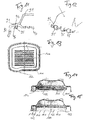
- FIG. 1 shows a schematic diagram of an embodiment of a heat exchanger 1 in the form of an indirect intercooler, which is attached to an intake module 2 of an internal combustion engine, not shown.
- the intake module 2 may be formed, for example, as a suction tube.
- the heat exchanger 1 consists of two coolant boxes 3, 4, wherein each coolant box 3, 4 is tightly sealed by a respective bottom 5, 6. Between the bottoms 5, 6 a fin-tube block 7 is arranged, which has a plurality of tubes 12, 13, 14, 15, in which a cooling liquid flows, through openings 9a in the bottom 5 and openings 10a in the bottom 6 in the coolant boxes 3 and 4 can occur.
- the coolant box 3 is approximately centrally separated by a partition wall 11, which divides the coolant box 3 into a distributor chamber 16 and a collecting space 17 for the coolant.
- the coolant which enters the distribution chamber 16 from a coolant channel, not shown, is fed through the openings 9 a in the tubes 12, 13 of the fin-tube block 7 and enters through the openings 10 a in the second coolant box 4 a. There, the coolant is deflected and returned through the openings 10 b of the bottom 6 via the tubes 14, 15 of the fin-tube block 7 and the openings 9 b in the bottom 5 in the collecting space 17 of the coolant box 3, where it leaves the coolant box 3.
- the coolant in the form of a cooling liquid preferably water or water-coolant mixture, thereby cools a charge air which is compressed and heated by a turbocharger (not shown) and flows through the fin-tube block 7 between the tubes 12, 13, 14, 15 .
- a turbocharger not shown
- 15 ribs 18 are arranged between the tubes 12, 13, 14, which touch the tubes. Through these ribs 18, the surface of the tubes 12, 13, 14, 15 is increased to absorb the heat from the charge air and the heat thus absorbed supplied to the coolant, which removes the heat from the heat exchanger 1. The cooled down charge air is then fed to the engine.
- FIG. 1 It can be seen that the first coolant box 3 and the sealing floor 5 are formed in their two-sided edge design so that they surround a part of the intake module 2 or the intake module 2.
- FIG. 2 an enlarged section of an edge region of the heat exchanger 1 in the region of the first coolant box 3 is shown.
- the designed as a cover first coolant box 3 in this case has a side part 3b, which has a base 3a, which extends parallel to the first bottom 5, an angle of greater than 90 ° and is bent in the direction of the first bottom 5.
- a portion 3c of the coolant box 3 connects, which is bent at an angle of more than 90 ° relative to the side part 3b and in turn extends parallel to the first bottom 5.
- a lateral flank 3d of the coolant box 3 extends at an angle of approximately 90 ° to the section 3c.
- the lateral flank 3d contacts the suction module 2, which is fitted between the lateral flank 3d and the finned tube block 7.
- the lateral flank 3 d comprises a corrugated slot flange 19 which is pressed against the intake module 2 for attaching the coolant box 3 to the intake module 2, wherein the coolant box 3 presses in the region 2 a of the intake module 2 is carried out and a mechanical attachment of the entire heat exchanger 1 via the first coolant box 3 to the intake module 2.
- the first coolant box 3 carries the entire heat exchanger. 1
- each end region of the trough-like first bottom 5 is formed as an inverted U-profile.
- a first non-functional gripper 5a of the U-profile extends at an angle of approximately 90 ° to the bottom 5 and extends in the direction of the coolant box 3.
- the adjoining this first leg 5a base region 5b, which in turn by approximately 90 ° relative to the first Leg 5a away from the first bottom 5 is bent, is aligned parallel to the portion 3 c of the first coolant box 3.
- the base portion 5b and the portion 3c abut against each other and are soldered together, if necessary, thereby preventing the coolant from leaking out of the first coolant box 3.
- the second leg 5c which adjoins the base region 5b and extends parallel to the first leg 5a, is shortened and engages in a recess 2b of the intake module 2.
- the second leg 5c is thereby spanned by the lateral flank 3d of the first coolant box 3.
- a groove 20 filled with a seal 20 is provided in the intake module 2 and runs approximately parallel to the first leg 5a of the U-shaped profile.
- both the first floor 5 and the first coolant box 3 are constructed symmetrically in their end regions.
- the first coolant box 3 is placed after soldering to the first bottom 5 on the intake module 2 and mechanically connected by crimping, ie pressing the Wellschlitzbördelung 19 against the intake module 2.
- the seal 20 is pressed against the base portion 5 b of the bottom 5, whereby a tight seal between the intake module 2 and the fin-tube block 7 is achieved.
- the illustrated heat exchanger 1 realizes despite utilization of only a small amount of space in the motor vehicle, a high cooling capacity of the charge air.
- FIG. 2 shows an embodiment of the invention, in which the fin-tube block is sealed by a bottom 5 opposite a Kühtmittetkasten 3.
- the bottom 5 in this case has an end portion which is U-shaped and which is soldered to the coolant box.
- the tube plate 50 is formed substantially flat, wherein it has a circumferential wall 51 which is aligned substantially perpendicular to the plane of the tube plate 50 and which faces from the tube plate in the direction of the coolant box.
- the coolant box 52 is formed with an outer planar wall having a circumferential wall 53 which is formed substantially parallel to the plane of the area 512. Between the area 53 and the area 51, a solder joint may be provided to seal the coolant box from the ground.
- an L-shaped region 54 is provided, which is formed by the region 55 and the region 56.
- the region 55 is aligned essentially flat and parallel to the plane of the tube bottom 50, the region 56 substantially aligned parallel to the area 53.
- the L-shaped region forms on its inside a receptacle 57 for a foot of a housing or a suction module and possibly a seal for the positive connection of the coolant box of the heat exchanger with the intake module or with the housing.
- the positive connection can, for example, by a Wellenschlitzbördelung o.ä. be made.
- FIG. 6 shows a detail of FIG. 5 , wherein the coolant box 52 has a projecting portion 57, in which an approximately U-shaped receptacle 58 of the tube plate engages.
- the projecting portion 57 serves to fix the bottom 50 to the coolant box 52.
- the connection between The region 56 of the coolant box 52 and a foot of a housing or an intake module arranged in this space region 57 can be made, for example, by means of a corrugated slot flange or another type of flanging.
- FIG. 7 shows another embodiment in which the bottom 70 has a substantially planar portion 71 containing the tube openings 72.
- an edge region 73 is formed, which is substantially planar. Outside this edge region 73, a section U-shaped region 74 is provided, which serves to receive fastening means.
- the coolant box 75 is formed as a closed box on five sides, which has an edge portion 76 which is substantially planar.
- the configuration of the edge region 76 corresponds to the configuration of the edge region 73, so that the edge region 76 can be placed flat on the edge region 73 and soldered to it, as shown in FIG FIG. 8 can be seen.
- FIG. 9 shows this embodiment again in a section.
- the bottom 70 with a flat edge region 73 has at its outer region on the U-shaped circumferential portion 74.
- the coolant box 75 is placed with its likewise flat edge region 76 such that the edge region 76 can be soldered substantially flat with the edge region 73 of the tube bottom.
- the U-shaped portion 74 serves to receive a flange, for example a housing or a suction module.
- the U-shaped region 80 of the tube bottom serves to receive the foot 81 of a housing or a suction module, wherein the lateral edge region 82 serves for crimping the U-shaped region of the tube bottom with the foot 81.
- the coolant box 83 is formed with the tube plate 84 by means of a connector 85 connectable.
- the coolant box tongues at its end, which can engage through openings or slots in the tube sheet 84 and causes a positive connection between the bottom 84 and the coolant box 83, for example, by rotation or deformation before the solder joint, the two components 83, 84th sealed together materially connects.
- the positive connection between the bottom 84 and the coolant box 83 serves to pre-fix the parts before the soldering process.
- the FIG. 11 shows this again in a further embodiment.
- the tube sheet 90 has a flat region 91 and a lateral wall region 92.
- the flat portion 91 serves to abut a flat portion 93 of the coolant box 94, from the flat portion 93 tongues 95 are exposed, which protrude perpendicular to the plane of the flat portion 93 and which pass through openings 96 of the flat portion 91 of the tube sheet. If these tongues are bent or twisted, then a positive connection between the coolant box 94 and the bottom 90 can be generated.
- FIG. 12 shows this again in a side view, wherein the flat portion 93 is interrupted by tongues 95, which protrude from the plane of the flat portion 93 in the vertical direction.
- FIG. 13 shows a bottom 100, which has opposite the rectangular shape, two arcuate portions 101, 102. These arcuate contours serve to increase the pressure resistance of the tubesheet. It can be seen that the area 101 bulges at the edge over the entire width of the floor or is formed bent and the area 102 is formed only over about half the extent of the width of the bottom.
- the tubesheet 110 is formed with a planar area 111 in which the openings and the passages 112 are provided for the tubes of the heat exchanger.
- the region 111 is essentially planar.
- the tube bottom 120 has a bulge 122 in the region of the passages 121, such that the edge regions 123 and the middle region between the passages 124 are arranged essentially on the same plane.
- the passages 121 are convexly curved toward the outside of the coolant box.
- FIGS. 16 and 17 show further embodiments of a floor-coolant box connection, wherein between the bottom 130 and the coolant box 131 is a solder joint and the bottom 130 forms together with the coolant box 131, the U-shaped contour 132 for receiving a seal and a foot of a housing or a Sagmoduls ,
- the tube plate 130 starting from its flat circumferential surface 133, an L-shaped portion 134 which, together with an L-shaped portion 135 with the side wall 136, the U-shaped portion for receiving the foot 137 of the housing or the Intake module forms.
- the seal 138 is arranged so that when crimping the foot 137 with the side wall 136, the seal 138 is pressed.
- FIG. 17 another embodiment is shown, in which the foot 140 has a substantially U-shaped receptacle 141, in which the seal 142 is inserted, so that the seal at least partially protruding from the U-shaped area and pressed against the area 143 of the tube bottom 144.
- FIG. 18 shows a further embodiment in which the bottom 150 is positively connected to the coolant box 151 such that the coolant box has at its corner portions slots 152 through which tongues 153 of the tube sheet pass through.
Landscapes
- Engineering & Computer Science (AREA)
- Physics & Mathematics (AREA)
- Thermal Sciences (AREA)
- Chemical & Material Sciences (AREA)
- Combustion & Propulsion (AREA)
- Mechanical Engineering (AREA)
- General Engineering & Computer Science (AREA)
- Heat-Exchange Devices With Radiators And Conduit Assemblies (AREA)
Abstract
Description
- Die Erfindung betrifft einen Wärmetauscher, der an einem Ansaugmodul eines Verbrennungsmotors befestigt ist, umfassend einen ersten und einen zweiten Kühlmittelkasten zwischen welchen sich ein Rippen-Rohr-Block erstreckt, wobei die Rohre des Rippen-Rohr- Blockes in jeweils einen Boden münden und der jeweils eine Boden dicht mit dem jeweiligen Kühlmittelkasten verbunden ist.
- Um den Zielkonflikt aus Fahrleistung, Verbrauch und Emissionen im Kraftfahrzeug besser auflösen zu können, werden moderne Verbrennungsmotoren in immer stärkerem Maße durch vorgeschaltete Turbolader aufgeladen. Daraus ergeben sich steigende Anforderungen an die Ladeluftkühlung.
- Zur Kühlung der Ladeluft eines Verbrennungsmotors sind im Wesentlichen zwei Verfahren bekannt. Bei dem ersten Verfahren wird einem, als direkten Ladeluftkühler ausgebildeten Wärmetauscher die von dem Turbolader komprimierte und erhitzte Ladeluft zugeführt, wobei diese Ladeluft mittels dem, durch die Bewegung des Kraftfahrzeuges auftretenden Fahrtwind abgekühlt wird.
- Eine verbesserte Kühlleistung wird durch die Verwendung eines Wärmetauschers in Form eines indirekten Ladeluftkühlers erreicht, welcher aus zwei Kühlmittelkästen besteht, zwischen denen ein Rippen-Rohr-Block angeordnet ist, wobei eine Kühlflüssigkeit durch die Rohre des Rippen-Rohr-Blocks und die Kühlmittelkästen geführt ist. Der Rippen-Rohr-Block ist beidseitig von je einem Boden abgeschlossen, wobei die Böden Öffnungen zur Aufnahme der Rohre des Rippen-Rohr-Blockes aufweisen, durch die die Kühlflüssigkeit in den ersten und den zweiten Kühlmittelkasten fließt. Dabei weist der erste Kühlmittelkasten einen Kühlmittelzufluss und der zweite Kühlmittelkasten einen Kühlmittelabfluss auf.
- Insbesondere die als indirekte Ladeluftkühler ausgebildeten Wärmetauscher werden üblicherweise nah am Verbrennungsmotor angebracht und erfordern eine optimierte Anpassung an den im Kraftfahrzeug zur Verfügung stehenden Bauraum. Dabei wird der Wärmetauscher im Allgemeinen über Flanschlösungen unter Verwendung von Form- und Flachdichtungen an einem Ansaugmodul des Verbrennungsmotors befestigt. Es ist auch bekannt, dass der Wärmetauscher durch eine Vercrimpung seines Bodens mit dem Ansaugmodul des Verbrennungsmotors an diesem befestigt ist. Auch sind unlösbare Verbindungen wie beispielsweise mittels Schweißen bekannt.
- Der Erfindung liegt die Aufgabe zu Grunde, einen Wärmetauscher anzugeben, der an dem Ansaugmodul des Verbrennungsmotors befestigt ist, wobei bei minimalen Abmessungen des Wärmetauschers große Freiheitsgrade für die Formgestaltung des Wärmetauschers gegeben sind.
- Erfindungsgemäß wird die Aufgabe dadurch gelöst, dass der erste und/oder der zweite Kühlmittelkasten, vorzugsweise den Wärmetauscher tragend, an dem Ansaugmodul des Verbrennungsmotors befestigt ist. Dies hat den Vorteil, dass die Abmessungen des Wärmetauschers minimiert werden können, wobei die Formgestaltung der Kühlmittelkästen vielfältig an den vorhandenen Bauraum nahe dem Verbrennungsmotor angepasst werden können. Der Wärmetauscher kann dabei komfortabel am Ansaugmodul des Verbrennungsmotors, vorzugsweise entweder am Ansaugkrümmer oder dem Zylinderkopfbereich, positioniert werden.
- Vorteilhafterweise ist der erste und/oder der zweite Kühlmittelkasten über den Boden des Rippen-Rohr-Blockes gezogen und liegt an dem Ansaugmodul des Verbrennungsmotors an. Dadurch wird der gesamte Wärmetauscher durch den Kühlmittelkasten gehalten, wobei die Kühlmittelkästen optimal in ihrer Form an den, nahe dem Verbrennungsmotor vorhandenen Bauraum anpassbar sind.
- In einer Ausgestaltung überragt mindestens eine seitliche Flanke des ersten und/oder zweiten Kühlmittelkastens den Boden, wobei das Ansaugmodul des Verbrennungsmotors zwischen der seitlichen Flanke und dem Boden eingreift. Dadurch, dass die seitliche Flanke das Ansaugmodul weit umfasst, wird gewährleistet, dass der Wärmetauscher sicher von dem Ansaugmodul gehalten wird. Dies wird insbesondere auch dadurch unterstützt, dass das Ansaugmodul in eine Aufnahme eingreift, welche von der seitlichen Flanke des ersten und/oder des zweiten Kühlmittelkastens und dem Boden gebildet ist.
- In einer Variante ist die seitliche Flanke des ersten und/oder des zweiten Kühlmittelkastens mit dem Ansaugmodul des Verbrennungsmotors, vorzugsweise einem Gehäuse eines Saugrohres, verbördelt, insbesondere vercrimpt. Eine solche Verbördelung bzw. Vercrimpung nimmt wesentlich weniger Platz in Anspruch als eine Flanschlösung, so dass der Platzbedarf für einen solchen Wärmetauscher reduziert wird.
- In einer Weiterbildung weist die seitliche Flanke mindestens eine Wellschlitzbördelung zur Befestigung des ersten oder des zweiten Kühlmittelkastens an dem Ansaugmodul auf. Durch diese Wellschlitzbördelung wird der Kühlmittelkasten mittels eines besonders einfachen und kostengünstig ausführbaren Verbindungsverfahrens an dem Ansaugmodul mechanisch arretiert.
- Vorteilhafterweise ist das Ansaugmodul mindestens teilweise von einem Endbereich des Bodens umspannt, wobei dieser Endbereich sich annähernd parallel zu dem Abschnitt des ersten oder zweiten Kühlmittelkastens erstreckt, an welchen sich die seitliche Flanke anschließt. Dadurch wird die Passgenauigkeit des Ansaugmoduls in die von seitlicher Flanke und Endbereich des Bodens geschaffene Aufnahme verbessert und die Befestigung des Kühlmittelkastens an dem Ansaugmodul neben der Verbördelung durch eine annähernd vorhandene Formschlüssigkeit erhöht.
- In einer weiteren Ausführungsform ist der Endbereich des Bodens mindestens mit dem parallel verlaufenden Abschnitt des ersten oder zweiten Kühlmittelkastens verlötet. Durch die Verlötung ist der Kühlmittelkasten dicht verschlossen, so dass ein Austritt des, in dem Kühlmittelkasten enthaltenen Kühlmittels aus dem Kühlmittelkasten zuverlässig verhindert wird.
- In einer Ausgestaltung ist zwischen dem Endbereich des Bodens und dem Ansaugmodul des Verbrennungsmotors zur Unterbindung der Ausströmung einer durch die Rippen des Rippen-Rohr-Blockes strömenden Ladeluft ein Dichtelement vorgesehen. Dieses Dichtelement begrenzt den Bereich des Wärmetauschers, durch den die Ladeluft, welche durch das Kühlmittel abgekühlt werden soll, hindurchströmt.
- In einer besonders einfachen Ausführungsform ist das Dichtelement in das Ansaugmodul integriert oder eingelegt. Dabei kann das Dichtelement vorteilhafterweise als Gummidichtung oder Silikondichtung ausgebildet sein, welche entweder als separates Bauteil bei der Montage des Wärmetauschers einfach in den abzudichtenden Bereich eingelegt wird oder bereits bei der Herstellung des Ansaugmoduls an der entsprechenden Stelle außen am Ansaugmodul positioniert ist. Die Verwendung einer Gummidichtung erlaubt eine sehr kostengünstige Herstellung.
- In einer anderen Variante zirkuliert in dem ersten und dem zweiten Kühlmittelkasten und den Rohren des Rippen-Rohr-Blockes als Kühlmittel eine Kühlflüssigkeit, wobei insbesondere der erste Kühlmittelkasten eine Trennwand aufweist, durch welche der erste Kühlmittelkasten in zwei Teilräume unterteilt wird, wobei der erste Teilraum als Verteilerraum und der zweite Teilraum als Sammelraum für die Kühlflüssigkeit dient. Durch die Unterteilung des ersten Kühlmittelkasten werden der Zufluss als auch der Abfluss des Kühlmittels in ein und dieselbe Richtung möglich, was ebenfalls zur Verringerung des, von dem Wärmetauscher benötigten Bauraumes beträgt, da die mit dem Zufluss und dem Abfluss in Verbindung stehenden Leitungen platzsparend im Motorraum des Kraftfahrzeuges verlegt werden können.
- Die Erfindung lässt zahlreiche Ausführungsbeispiele zu. Eines davon soll anhand der in der Zeichnung dargestellten Figuren näher erläutert werden.
- Es zeigt:
- Figur 1:
- Prinzipdarstellung eines Ausführungsbeispiels für den erfindungsgemäßen Wärmetauscher,
- Figur 2:
- ein Ausschnitt aus dem Wärmetauscher nach
Figur 1 , - Figur 3:
- Darstellung des ersten Bodens des Wärmetauschers nach
Figur 1 , - Figur 4:
- Darstellung des ersten Kühlmittelkastens des Wärmetauschers nach
Figur 1 , - Figur 5:
- eine Teilansicht einer Boden-Kühlmittelkasten-Verbindung,
- Figur 6:
- ein Ausschnitt der
Figur 5 , - Figur 7:
- eine Ansicht eines Boden und eines Kühlmittelkasten,
- Figur 8:
- eine Ansicht des auf den Boden aufgesetzten Kühlmittelkastens,
- Figur 9:
- eine Teilansicht einer Boden-Kühlmittelkasten-Verbindung,
- Figur 10:
- eine Teilansicht einer Boden-Kühlmittelkasten-Verbindung,
- Figur 11:
- eine Teilansicht einer Boden-Kühlmittelkasten-Verbindung,
- Figur 12:
- eine Ansicht des Kühlmittelkastens von der Seite,
- Figur 13:
- eine Ansicht eines Bodens von unten,
- Figur 14:
- eine Schnittdarstellung einer Boden-Kühlmittelkasten-Verbindung,
- Figur 15:
- eine Schnittdarstellung einer Boden-Kühlmittelkasten-Verbindung,
- Figur 16:
- eine Teilansicht einer Boden-Kühlmittelkasten-Verbindung,
- Figur 17:
- eine Teilansicht einer Boden-Kühlmittelkasten-Verbindung, und
- Figur 18:
- eine Ansicht eines Bodens von unten.
- Gleiche Merkmale sind mit gleichen Bezugszeichen gekennzeichnet.
-
Figur 1 zeigt eine Prinzipdarstellung eines Ausführungsbeispiels eines Wärmetauschers 1 in Form eines indirekten Ladeluftkühlers, welcher an einem Ansaugmodul 2 eines nicht weiter dargestellten Verbrennungsmotors befestigt ist. Das Ansaugmodul 2 kann beispielsweise als Saugrohr ausgebildet sein. - Der Wärmetauscher 1 besteht aus zwei Kühlmittelkästen 3, 4, wobei jeder Kühlmittelkasten 3, 4 dicht von je einem Boden 5, 6 abgeschlossen ist. Zwischen den Böden 5, 6 ist ein Rippen-Rohr-Block 7 angeordnet, welcher mehrere Rohre 12, 13, 14, 15 aufweist, in welchen eine Kühlflüssigkeit strömt, die durch Öffnungen 9a im Boden 5 und Öffnungen 10a im Boden 6 in die Kühlmittelkästen 3 und 4 eintreten kann.
- Der Kühlmittelkasten 3 ist dabei annähernd mittig durch eine Trennwand 11 getrennt, die den Kühlmittelkasten 3 in einen Verteilerraum 16 und einen Sammelraum 17 für das Kühlmittel unterteilt. Das Kühlmittel, welches aus einem nicht weiter dargestellten Kühlmittelkanal in den Verteilerraum 16 eintritt, wird durch die Öffnungen 9a in die Rohre 12, 13 des Rippen-Rohr-Blockes 7 eingespeist und tritt durch die Öffnungen 10a in den zweiten Kühlmittelkasten 4 ein. Dort wird das Kühlmittel umgelenkt und durch die Öffnungen 10b des Bodens 6 über die Rohre 14, 15 des Rippen-Rohr-Blocks 7 und die Öffnungen 9b im Boden 5 in den Sammelraum 17 des Kühlmittelkastens 3 zurückgeführt, wo es den Kühlmittelkasten 3 verlässt.
- Das Kühlmittel in Form einer Kühlflüssigkeit, vorzugsweise Wasser oder Wasser-Kühlmittel-Gemisch, kühlt dabei eine, von einem nicht weiter dargestellten Turbolader komprimierte und aufgeheizte Ladeluft, welche den Rippen-Rohr-Block 7 zwischen den Rohren 12, 13, 14, 15 durchströmt. Um den Wärmeaustausch zwischen der Ladeluft und dem Kühlmittel zu erhöhen, sind zwischen den Rohren 12, 13, 14, 15 Rippen 18 angeordnet, welche die Rohre berühren. Durch diese Rippen 18 wird die Oberfläche der Rohre 12, 13, 14, 15 zur Aufnahme der Wärme aus der Ladeluft erhöht und die so aufgenommene Wärme dem Kühlmittel zugeführt, welches die Wärme aus dem Wärmetauscher 1 abtransportiert. Die so herunter gekühlte Ladeluft wird dann dem Verbrennungsmotor zugeführt.
- Wie aus
Figur 1 ersichtlich sind der erste Kühlmittelkasten 3 und der diesen abdichtende Boden 5 in ihrer beidseitigen Randgestaltung so ausgebildet, dass diese einen Teil des Ansaugmoduls 2 oder das Ansaugmodul 2 umgreifen. InFigur 2 ist ein vergrößerter Ausschnitt eines Randbereiches des Wärmetauscher 1 im Bereich des ersten Kühlmittelkastens 3 dargestellt. Der als Abdeckung ausgebildete erste Kühlmittelkasten 3 weist dabei ein Seitenteil 3b auf, welches zu einem Grundteil 3a, das sich parallel zum ersten Boden 5 erstreckt, einen Winkel von größer 90° aufweist und in Richtung des ersten Bodens 5 gebogen ist. An dieses Seitenteil 3b schließt sich ein Abschnitt 3c des Kühlmittelkastens 3 an, welcher um einen Winkel von mehr als 90° gegenüber dem Seitenteil 3b gebogen ist und sich wiederum parallel zum ersten Boden 5 ausdehnt. Ausgehend von diesem Abschnitt 3c erstreckt sich eine seitliche Flanke 3d des Kühlmittelkastens 3 in einem Winkel von annähernd 90° zu dem Abschnitt 3c. Die seitliche Flanke 3d berührt das Ansaugmodul 2, welches zwischen der seitlichen Flanke 3d und dem Rippen-Rohr-Block 7 eingepasst ist. In der Nähe seines, von dem Abschnitt 3c abgewandten Endes umfasst die seitliche Flanke 3d eine Wellschlitzbördelung 19, welche zum Befestigen des Kühlmittelkastens 3 an dem Ansaugmodul 2 gegen das Ansaugmodul 2 gepresst wird, wobei der Kühlmittelkasten 3 im Bereich 2a des Ansaugmoduls 2 mit diesem verpresst wird und eine mechanische Befestigung des gesamten Wärmetauschers 1 über den ersten Kühlmittelkasten 3 an dem Ansaugmodul 2 erfolgt. Dabei trägt der erste Kühlmittelkasten 3 den gesamten Wärmetauscher 1. - Zur Abdichtung des ersten Kühlmittelkastens 3 ist der erste Boden 5 mit diesem verlötet. Dazu ist jeder Endbereich des wannenähnlich ausgebildeten ersten Bodens 5 als ein umgekehrtes U-Profil ausgebildet. Ein erster Sachenkel 5a des U-Profils verläuft dabei in einem Winkel von annähernd 90° zu dem Boden 5 und erstreckt sich in Richtung des Kühlmittelkastens 3. Der sich an diesen ersten Schenkel 5a anschließende Basisbereich 5b, welcher wiederum um annähernd 90° gegenüber dem ersten Schenkel 5a weg von dem ersten Boden 5 gebogen ist, ist parallel zu dem Abschnitt 3c des ersten Kühlmittelkastens 3 ausgerichtet. Der Basisbereich 5b und der Abschnitt 3c liegen aneinander an und sind, ggf. flächig, miteinander verlötet, wodurch verhindert wird, dass das Kühlmittel aus dem ersten Kühlmittelkasten 3 austreten kann. Der zweite Schenkel 5c, welcher an den Basisbereich 5b anschließt und parallel zu dem ersten Schenkel 5a verläuft, ist verkürzt ausgebildet und greift in eine Ausnehmung 2b des Ansaugmoduls 2 ein. Der zweite Schenkel 5c wird dabei von der seitlichen Flanke 3d des ersten Kühlmittelkastens 3 überspannt.
- Um zu verhindern, dass zwischen dem ersten Boden 5 und dem Ansaugmodul 2 Ladeluft aus dem Wärmetauscher 1 entweicht, ist in dem Ansaugmodul 2 eine mit einer Dichtung 20 ausgefüllte Nut vorgesehen, die annähernd parallel zum ersten Schenkel 5a des U-förmigen Profils verläuft.
- In
Figur 3 ist noch einmal der gesamte erste Boden 5 dargestellt, während inFigur 4 der gesamte, als Abdeckung ausgebildete erste Kühlmittelkörper 3 dargestellt ist. Wie aus beidenFiguren 3, 4 ersichtlich, sind sowohl der erste Boden 5 als auch der erste Kühlmittelkasten 3 symmetrisch in ihren Endbereichen aufgebaut. Dabei wird der erste Kühlmittelkasten 3 nach dem Verlöten mit dem ersten Boden 5 auf das Ansaugmodul 2 aufgesetzt und durch Vercrimpen, d.h. Eindrücken der Wellschlitzbördelung 19 gegen das Ansaugmodul 2, mit diesem mechanisch verbunden. Beim Vercrimpen des ersten Kühlmittelkastens 3 mit dem Ansaugmodul 2 wird die Dichtung 20 gegen den Basisbereich 5b des Bodens 5 gepresst, wodurch ein dichter Abschluss zwischen dem Ansaugmodul 2 und dem Rippen-Rohr-Block 7 erreicht wird. - Der erläuterte Wärmetauscher 1 realisiert trotz Inanspruchnahme von nur wenig Bauraum im Kraftfahrzeug eine hohe Kühlleistung der Ladeluft.
- Die
Figur 2 zeigt ein Ausführungsbeispiel der Erfindung, bei welchem der Rippen-Rohr-Block durch einen Boden 5 gegenüber einem Kühtmittetkasten 3 abgedichtet verbunden ist. Der Boden 5 weist dabei einen Endbereich auf, der U-förmig gebildet ist und der mit dem Kühlmittelkasten verlötet ist. - Bei alternativen Ausführungsbeispielen gemäß
Figur 5 ist der Rohrboden 50 im Wesentlichen eben ausgebildet, wobei er eine umlaufende Wandung 51 aufweist, die im Wesentlichen senkrecht zur Ebene des Rohrbodens 50 ausgerichtet ist und die vom Rohrboden in Richtung zum Kühlmittelkasten weist. Der Kühlmittelkasten 52 ist mit einer äußeren ebenen Wandung ausgebildet, die eine umlaufende Wandung 53 aufweist, die im Wesentlichen parallel zur Ebene des Bereichs 512 ausgebildet ist. Zwischen dem Bereich 53 und dem Bereich 51 kann eine Lötverbindung vorgesehen sein, um den Kühlmittelkasten gegenüber dem Boden abzudichten. - Im Anschluss an den Bereich 53 ist ein L-förmiger Bereich 54 vorgesehen, der gebildet ist durch den Bereich 55 sowie den Bereich 56. Der Bereich 55 ist im Wesentlichen eben und parallel zu der Ebene des Rohrbodens 50 ausgerichtet, wobei der Bereich 56 im Wesentlichen parallel zum Bereich 53 ausgerichtet ist.
- Der L-förmige Bereich bildet auf seiner Innenseite eine Aufnahme 57 für einen Fuß eines Gehäuses bzw. eines Ansaugmoduls sowie ggf. eine Dichtung zur formschlüssigen Verbindung des Kühlmittelkastens des Wärmeübertragers mit dem Ansaugmodul oder mit dem Gehäuse. Die formschlüssige Verbindung kann beispielsweise durch eine Wellenschlitzbördelung o.ä. vorgenommen werden.
- Die
Figur 6 zeigt ein Detail derFigur 5 , wobei der Kühlmittelkasten 52 einen vorspringenden Bereich 57 aufweist, in den eine etwa U-förmige Aufnahme 58 des Rohrbodens eingreift. Der vorspringende Bereich 57 dient der Fixierung des Bodens 50 mit dem Kühlmittelkasten 52. Die Verbindung zwischen dem Bereich 56 des Kühlmittelkastens 52 und einem in diesem Raumbereich 57 angeordneten Fuß eines Gehäuses oder eines Ansaugmoduls kann beispielsweise mittels einer Wellenschlitzbördelung oder einer anderen Art einer Bördelung vorgenommen sein. - Die
Figur 7 zeigt ein weiteres Ausführungsbeispiel, bei welchem der Boden 70 einen im Wesentlichen ebenen Bereich 71 aufweist, welcher die Rohröffnungen 72 enthält. Um die Rohröffnungen 72 herum ist ein Randbereich 73 ausgebildet, der im Wesentlichen eben ist. Außerhalb dieses Randbereichs 73 ist ein im Schnitt U-förmiger Bereich 74 vorgesehen, der zur Aufnahme von Befestigungsmitteln dient. Der Kühlmittelkasten 75 ist als auf fünf Seiten geschlossener Kasten ausgebildet, der einen Randbereich 76 aufweist, der im Wesentlichen eben ist. Die Ausgestaltung des Randbereichs 76 entspricht der Ausgestaltung des Randbereichs 73, so dass der Randbereich 76 auf den Randbereich 73 eben aufgesetzt und mit diesem verlötet werden kann, wie es in derFigur 8 zu erkennen ist. - Die
Figur 9 zeigt diese Ausgestaltung noch einmal in einem Schnitt. Der Boden 70 mit einem ebenen Randbereich 73 weist an seinem äußeren Bereich den U-förmig umlaufenden Bereich 74 auf. Auf den Boden im Bereich des Randes 73 ist der Kühlmittelkasten 75 mit seinem ebenfalls ebenen Randbereich 76 derart aufgesetzt, dass der Randbereich 76 mit dem Randbereich 73 des Rohrbodens im Wesentlichen flächig verlötbar ist. - Der U-förmige Bereich 74 dient zur Aufnahme eines Flansches, beispielsweise eines Gehäuses oder eines Ansaugmoduls.
- In
Figur 10 ist eine solche Gestaltung gezeigt. Der U-förmige Bereich 80 des Rohrbodens dient zur Aufnahme des Fußes 81 eines Gehäuses oder eines Ansaugmoduls, wobei der seitliche Randbereich 82 zur Verbördelung des U-förmigen Bereichs des Rohrbodens mit dem Fuß 81 dient. - Im Ausführungsbeispiel der
Figur 10 ist weiterhin zu erkennen, dass der Kühlmittelkasten 83 mit dem Rohrboden 84 mittels einer Steckverbindung 85 verbindbar ausgebildet ist. Dazu weist der Kühlmittelkasten Zungen an seinem Endbereich auf, die durch Öffnungen bzw. Schlitze im Rohrboden 84 eingreifen können und die beispielsweise durch Verdrehung oder Verformung eine formschlüssige Verbindung zwischen dem Boden 84 und dem Kühlmittelkasten 83 bewirkt, bevor die Lötverbindung die beiden Bauteile 83, 84 abgedichtet miteinander stoffschlüssig verbindet. Die formschlüssige Verbindung zwischen dem Boden 84 und dem Kühlmittelkasten 83 dient der Vorfixierung der Teile vor dem Lötprozess. - Die
Figur 11 zeigt dies noch einmal in einem weiteren Ausführungsbeispiel. Der Rohrboden 90 weist einen ebenen Bereich 91 und einen seitlichen Wandbereich 92 auf. Der ebene Bereich 91 dient der Anlage eines ebenen Bereichs 93 des Kühlmittelkastens 94, wobei aus dem ebenen Bereich 93 Zungen 95 herausgestellt sind, die senkrecht zur Ebene des ebenen Bereichs 93 hervorstehen und die durch Öffnungen 96 des ebenen Bereichs 91 des Rohrbodens hindurch treten. Werden diese Zungen verbogen oder verdreht, so kann eine formschlüssige Verbindung zwischen dem Kühlmittelkasten 94 und dem Boden 90 erzeugt werden. - Die
Figur 12 zeigt dies noch einmal in einer seitlichen Ansicht, wobei der ebene Bereich 93 durch Zungen 95 unterbrochen ist, die von der Ebene des ebenen Bereichs 93 in senkrechter Richtung hervorstehen. - Die
Figur 13 zeigt einen Boden 100, der entgegen der rechteckigen Gestaltung zwei bogenförmige Bereiche 101, 102 aufweist. Diese bogenförmigen Konturen dienen der Steigerung der Druckfestigkeit des Rohrbodens. Dabei ist zu erkennen, dass der Bereich 101 sich am Rand über die gesamte Breite des Bodens wölbt bzw. derart gebogen ausgebildet ist und der Bereich 102 lediglich nur über etwa die halbe Erstreckung der Breite des Bodens ausgebildet ist. - In einem weiteren Ausführungsbeispiel gemäß
Figur 14 ist der Rohrboden 110 mit einem ebenen flächigen Bereich 111 ausgebildet, in welchem die Öffnungen und die Durchzüge 112 für die Rohre des Wärmeübertragers vorgesehen sind. Der Bereich 111 ist dabei im Wesentlichen eben ausgebildet. - In einem alternativen Ausführungsbeispiel gemäß
figur 15 weist der Rohrboden 120 im Bereich der Durchzüge 121 eine Wölbungen 122 auf, derart, dass die Randbereiche 123 und der mittleren Bereich zwischen den Durchzügen 124 im Wesentlichen auf gleicher Ebene angeordnet sind. Die Durchzüge 121 sind hingegen konvex gewölbt in Richtung auf die Außenseite des Kühlmittelkastens. - Die
Figuren 16 und 17 zeigen weitere Ausführungsbeispiele einer Boden-Kühlmittelkasten-Verbindung, wobei zwischen dem Boden 130 und dem Kühlmittelkasten 131 eine Lötverbindung besteht und der Boden 130 gemeinsam mit dem Kühlmittelkasten 131 die U-förmige Kontur 132 zur Aufnahme einer Dichtung und eines Fußes eines Gehäuses oder eines Sagmoduls bildet. Dazu weist der Rohrboden 130, ausgehend von seiner ebenen umlaufenden Fläche 133, einen L-förmigen Bereich 134 auf, der gemeinsam mit einem L-förmigen Bereich 135 mit der Seitenwand 136 den U-förmigem Bereich zur Aufnahme des Fußes 137 des Gehäuses bzw. des Ansaugmoduls bildet. Auch ist in diesem U-förmigen Bereich zwischen dem Fuß 137 die Dichtung 138 angeordnet, so dass bei einer Verbördelung des Fußes 137 mit der Seitenwand 136 die Dichtung 138 verpresst wird. - In
Figur 17 ist ein weiteres Ausführungsbeispiel gezeigt, bei welchem der Fuß 140 eine im Wesentlichen U-förmige Aufnahme 141 aufweist, in die die Dichtung 142 eingesetzt ist, so dass die Dichtung zumindest teilweise aus dem U-förmigen Bereich herausragt und gegen den Bereich 143 des Rohrbodens 144 verpresst wird. - Die
Figur 18 zeigt ein weiteres Ausführungsbeispiel, bei welchem der Boden 150 mit dem Kühlmittelkasten 151 derart formschlüssig verbunden ist, dass der Kühlmittelkasten an seinen Eckbereichen Schlitze 152 aufweist, durch welche Zungen 153 des Rohrbodens hindurchgreifen. Derart kann eine Vorfixierung zwischen dem Boden und dem Kühtmittetkasten erzielt werden, so dass die Teile vor dem Löten lagesicher angeordnet werden können, so dass ein sicherer Lötvorgang durchgeführt werden kann.
Claims (10)
- Wärmetauscher, der an einem die Ansaugluft führenden Gehäuse, vorzugsweise an dem Ansaugmodul (2), eines Verbrennungsmotors befestigt ist, umfassend einen ersten und einen zweiten Kühlmittelkasten (3, 4) zwischen welchen sich ein Rippen-Rohr-Block (7) erstreckt, wobei die Rohre (12, 13, 14, 15) des Rippen-Rohr-Blockes (7) in jeweils einen Boden (5, 6) münden und jeweils einen Boden (5, 6) dicht mit dem jeweiligen Kühlmittelkasten (3, 4) verbunden sind, dadurch gekennzeichnet, dass der erste und/oder der zweite Kühlmittelkasten (3,4), vorzugsweise den Wärmetauscher (1) tragend, an einem die Ansaugluft führenden Gehäuse, vorzugsweise an dem Ansaugmodul (2) des Verbrennungsmotors befestigt ist.
- Wärmetauscher nach Anspruch 1 dadurch gekennzeichnet, dass der erste und/oder der zweite Kühtmitteikasten (3, 4) über den Boden (5, 6) des Rippen-Rohr-Blockes (7) gezogen ist und an dem Ansaugmodul (2) des Verbrennungsmotors anliegt.
- Wärmetauscher nach Anspruch 2, dadurch gekennzeichnet, dass mindestens eine seitliche Flanke (3d) des ersten und/oder zweiten Kühlmittelkastens (3, 4) den Boden (5, 6) überragt, wobei das Ansaugmodul (2) des Verbrennungsmotors zwischen der seitlichen Flanke (3d) und dem Boden (5, 6) eingreift.
- Wärmetauscher nach Anspruch 3, dadurch gekennzeichnet, dass die seitliche Flanke (3d) des ersten und/oder des zweiten Kühlmittelkastens (3, 4) mit dem Ansaugmodul (2) des Verbrennungsmotors, vorzugsweise einem Gehäuse eines Saugrohres, verbördelt, insbesondere vercrimpt, ist.
- Wärmetauscher nach Anspruch 4, dadurch gekennzeichnet, dass die seitliche Flanke (3d) mindestens eine Wellschlitzbördelung (19) oder eine Burgzinnenbördelung oder eine sonstige Bördelung zur Befestigung des ersten oder des zweiten Kühlmittelkastens (3, 4) an dem Ansaugmodul (2) aufweist.
- Wärmetauscher nach mindestens einem der vorhergehenden Ansprüche, dadurch gekennzeichnet, dass das Ansaugmodul (2) mindestens teilweise von einem Endbereich (5a, 5b, 5c) des Bodens (5) umspannt ist, wobei dieser Endbereich (5a, 5b, 5c) sich annähernd parallel zu dem Abschnitt (3c) des ersten oder zweiten Kühlmittelkastens (3) erstreckt, an welchen sich die seitliche Flanke (3d) anschließt.
- Wärmetauscher nach Anspruch 6, dadurch gekennzeichnet, dass der Endbereich (5a, 5b, 5c) des Bodens (5) mindestens mit dem parallel verlaufenden Abschnitt (3c) des ersten oder zweiten Kühlmittelkastens (3) verlötet ist.
- Wärmetauscher nach Anspruch 6 oder 7, dadurch gekennzeichnet, dass zwischen dem Endbereich (5a, 5b, 5c) des Bodens (5) und dem Ansaugmodul (2) des Verbrennungsmotors zur Unterbindung der Ausströmung einer, durch die Rippen (18) des Rippen-Rohr-Blockes (7) strömenden Ladeluft ein Dichtelement (20) vorgesehen ist.
- Wärmetauscher nach Anspruch 8, dadurch gekennzeichnet, dass das Dichtelement (20) in das Ansaugmodul (2) integriert oder eingelegt ist.
- Wärmetauscher nach mindestens einem der vorhergehenden Ansprüche, dadurch gekennzeichnet, dass in dem ersten und dem zweiten Kühlmittelkasten (3, 4) und den Rohren (12, 13, 14, 15) des Rippen-Rohr-Blockes (7) als Kühlmittel eine Kühlflüssigkeit zirkuliert, wobei insbesondere der erste Kühlmittelkasten (3) eine Trennwand (11) aufweist, durch welche der erste Kühlmittelkasten (3) in zwei Teilräume (16, 17) unterteilt wird, wobei ein erster Teilraum als Verteilerraum (16) und der zweite Teilraum (17) als Sammelraum für die Kühlflüssigkeit dient.
Applications Claiming Priority (1)
| Application Number | Priority Date | Filing Date | Title |
|---|---|---|---|
| DE102011077141A DE102011077141A1 (de) | 2011-06-07 | 2011-06-07 | Wärmetauscher |
Publications (3)
| Publication Number | Publication Date |
|---|---|
| EP2532855A2 true EP2532855A2 (de) | 2012-12-12 |
| EP2532855A3 EP2532855A3 (de) | 2015-03-25 |
| EP2532855B1 EP2532855B1 (de) | 2022-01-12 |
Family
ID=46197171
Family Applications (1)
| Application Number | Title | Priority Date | Filing Date |
|---|---|---|---|
| EP12171095.8A Not-in-force EP2532855B1 (de) | 2011-06-07 | 2012-06-06 | Wärmetauscher |
Country Status (2)
| Country | Link |
|---|---|
| EP (1) | EP2532855B1 (de) |
| DE (1) | DE102011077141A1 (de) |
Cited By (2)
| Publication number | Priority date | Publication date | Assignee | Title |
|---|---|---|---|---|
| DE102014008465A1 (de) * | 2014-06-06 | 2015-12-17 | Mahle International Gmbh | Wärmetauscher, insbesondere Abgaskühler |
| EP3086073A1 (de) | 2015-04-21 | 2016-10-26 | Neander Motors AG | Sauganlage mit integriertem ladeluftkühler |
Family Cites Families (7)
| Publication number | Priority date | Publication date | Assignee | Title |
|---|---|---|---|---|
| DE19515530C2 (de) * | 1995-04-27 | 2001-11-15 | Valeo Klimatech Gmbh & Co Kg | Wasserkasten eines Wärmetauschers für Kraftfahrzeuge |
| FR2856747B1 (fr) * | 2003-06-25 | 2005-09-23 | Valeo Thermique Moteur Sa | Module de refroidissement de l'air de suralimentation et des gaz d'echappement recircules d'un moteur a combustion interne de vehicule automobile. |
| DE102004027402A1 (de) * | 2004-06-04 | 2005-12-22 | Behr Gmbh & Co. Kg | Wärmetauscher |
| DE102005053924B4 (de) * | 2005-11-11 | 2016-03-31 | Modine Manufacturing Co. | Ladeluftkühler in Plattenbauweise |
| DE102007030464A1 (de) * | 2007-06-29 | 2009-01-08 | Volkswagen Ag | Saugrohr für eine Brennkraftmaschine |
| DE102009050258B3 (de) * | 2009-10-21 | 2010-11-18 | Mann + Hummel Gmbh | Saugrohr einer Brennkraftmaschine und Kühlfluidladeluftkühler |
| DE102009053884A1 (de) * | 2009-11-20 | 2011-06-01 | Behr Gmbh & Co. Kg | Saugrohr für einen Verbrennungsmotor |
-
2011
- 2011-06-07 DE DE102011077141A patent/DE102011077141A1/de not_active Withdrawn
-
2012
- 2012-06-06 EP EP12171095.8A patent/EP2532855B1/de not_active Not-in-force
Non-Patent Citations (1)
| Title |
|---|
| None |
Cited By (4)
| Publication number | Priority date | Publication date | Assignee | Title |
|---|---|---|---|---|
| DE102014008465A1 (de) * | 2014-06-06 | 2015-12-17 | Mahle International Gmbh | Wärmetauscher, insbesondere Abgaskühler |
| EP3086073A1 (de) | 2015-04-21 | 2016-10-26 | Neander Motors AG | Sauganlage mit integriertem ladeluftkühler |
| DE102015005047A1 (de) | 2015-04-21 | 2016-10-27 | Neander Motors Ag | Sauganlage mit integriertem Ladelüftkühler |
| US10060397B2 (en) | 2015-04-21 | 2018-08-28 | Neander Motors Ag | Intake unit comprising integrated charge air cooler |
Also Published As
| Publication number | Publication date |
|---|---|
| EP2532855A3 (de) | 2015-03-25 |
| EP2532855B1 (de) | 2022-01-12 |
| DE102011077141A1 (de) | 2012-12-13 |
Similar Documents
| Publication | Publication Date | Title |
|---|---|---|
| DE102013006956B4 (de) | Luftführendes Bauteil mit einem Ladeluftkühler | |
| EP2031338B1 (de) | Wärmetauscher | |
| EP2406474B1 (de) | Ladeluftkühler zur anordnung in einem saugrohr | |
| DE102018212070B4 (de) | U-förmiges Gehäuse und Deckel für Plattenwärmeübertrager | |
| EP3012570A1 (de) | Wärmetauscher | |
| DE102013006955A1 (de) | Saugrohr mit einem Ladeluftkühler | |
| EP2765286B1 (de) | Frischluftversorgungseinrichtung einer Brennkraftmaschine | |
| EP2652285B1 (de) | Vorrichtung zur kühlung von ladeluft, system zum konditionieren von ladeluft und ansaugmodul für einen verbrennungsmotor | |
| DE102010063602A1 (de) | Saugrohr mit integriertem Ladeluftkühler | |
| WO2009003562A1 (de) | Saugrohr für eine brennkraftmaschine | |
| DE3720483A1 (de) | Waermetauscher | |
| DE102012202234A1 (de) | Wärmeübertrageranordnung | |
| DE112017005178T5 (de) | Wärmetauscher mit Umgehungsdichtung mit Rückhalteklammer | |
| EP3237733B1 (de) | Ladeluftkühler-anordnung | |
| DE112017002622T5 (de) | Wärmetauscher | |
| WO2013107536A1 (de) | Saugrohr einer brennkraftmaschine mit einem kühlfluidladeluftkühler | |
| EP2532855A2 (de) | Wärmetauscher | |
| DE102018216659A1 (de) | Wärmeübertrager | |
| DE102008028263A1 (de) | Wärmeaustauscher | |
| DE102017201592B4 (de) | Platte für Kühler integriert in Motorblock/Sammler | |
| DE112015005646T5 (de) | Wärmetauscher mit mindestens einer baugruppe aus einem wärmeaustauschblock zwei sammelbehältern und einem gehäuse, das zur aufnahme der baugruppe in seinem inneren geeignet ist | |
| DE202012101622U1 (de) | Wärmeübertrager | |
| DE102014201264A1 (de) | Wärmeübertrager | |
| DE102018119812A1 (de) | Kunststoffbauteil-Metallbauteil-Kombination | |
| DE112015005663T5 (de) | Wärmetauscher mit mitteln, die die verbesserung der dichtigkeit des wärmetauschers ermöglichen |
Legal Events
| Date | Code | Title | Description |
|---|---|---|---|
| PUAI | Public reference made under article 153(3) epc to a published international application that has entered the european phase |
Free format text: ORIGINAL CODE: 0009012 |
|
| AK | Designated contracting states |
Kind code of ref document: A2 Designated state(s): AL AT BE BG CH CY CZ DE DK EE ES FI FR GB GR HR HU IE IS IT LI LT LU LV MC MK MT NL NO PL PT RO RS SE SI SK SM TR |
|
| AX | Request for extension of the european patent |
Extension state: BA ME |
|
| PUAL | Search report despatched |
Free format text: ORIGINAL CODE: 0009013 |
|
| AK | Designated contracting states |
Kind code of ref document: A3 Designated state(s): AL AT BE BG CH CY CZ DE DK EE ES FI FR GB GR HR HU IE IS IT LI LT LU LV MC MK MT NL NO PL PT RO RS SE SI SK SM TR |
|
| AX | Request for extension of the european patent |
Extension state: BA ME |
|
| RAP1 | Party data changed (applicant data changed or rights of an application transferred) |
Owner name: MAHLE BEHR GMBH & CO. KG |
|
| RIC1 | Information provided on ipc code assigned before grant |
Ipc: F02B 29/04 20060101AFI20150216BHEP |
|
| 17P | Request for examination filed |
Effective date: 20150925 |
|
| RBV | Designated contracting states (corrected) |
Designated state(s): AL AT BE BG CH CY CZ DE DK EE ES FI FR GB GR HR HU IE IS IT LI LT LU LV MC MK MT NL NO PL PT RO RS SE SI SK SM TR |
|
| 17Q | First examination report despatched |
Effective date: 20160503 |
|
| STAA | Information on the status of an ep patent application or granted ep patent |
Free format text: STATUS: EXAMINATION IS IN PROGRESS |
|
| GRAP | Despatch of communication of intention to grant a patent |
Free format text: ORIGINAL CODE: EPIDOSNIGR1 |
|
| STAA | Information on the status of an ep patent application or granted ep patent |
Free format text: STATUS: GRANT OF PATENT IS INTENDED |
|
| INTG | Intention to grant announced |
Effective date: 20210803 |
|
| GRAJ | Information related to disapproval of communication of intention to grant by the applicant or resumption of examination proceedings by the epo deleted |
Free format text: ORIGINAL CODE: EPIDOSDIGR1 |
|
| STAA | Information on the status of an ep patent application or granted ep patent |
Free format text: STATUS: EXAMINATION IS IN PROGRESS |
|
| GRAS | Grant fee paid |
Free format text: ORIGINAL CODE: EPIDOSNIGR3 |
|
| STAA | Information on the status of an ep patent application or granted ep patent |
Free format text: STATUS: GRANT OF PATENT IS INTENDED |
|
| GRAP | Despatch of communication of intention to grant a patent |
Free format text: ORIGINAL CODE: EPIDOSNIGR1 |
|
| INTC | Intention to grant announced (deleted) | ||
| GRAA | (expected) grant |
Free format text: ORIGINAL CODE: 0009210 |
|
| STAA | Information on the status of an ep patent application or granted ep patent |
Free format text: STATUS: THE PATENT HAS BEEN GRANTED |
|
| INTG | Intention to grant announced |
Effective date: 20211122 |
|
| AK | Designated contracting states |
Kind code of ref document: B1 Designated state(s): AL AT BE BG CH CY CZ DE DK EE ES FI FR GB GR HR HU IE IS IT LI LT LU LV MC MK MT NL NO PL PT RO RS SE SI SK SM TR |
|
| REG | Reference to a national code |
Ref country code: GB Ref legal event code: FG4D Free format text: NOT ENGLISH |
|
| REG | Reference to a national code |
Ref country code: CH Ref legal event code: EP |
|
| REG | Reference to a national code |
Ref country code: DE Ref legal event code: R096 Ref document number: 502012016973 Country of ref document: DE |
|
| REG | Reference to a national code |
Ref country code: IE Ref legal event code: FG4D Free format text: LANGUAGE OF EP DOCUMENT: GERMAN |
|
| REG | Reference to a national code |
Ref country code: AT Ref legal event code: REF Ref document number: 1462534 Country of ref document: AT Kind code of ref document: T Effective date: 20220215 |
|
| REG | Reference to a national code |
Ref country code: LT Ref legal event code: MG9D |
|
| REG | Reference to a national code |
Ref country code: NL Ref legal event code: MP Effective date: 20220112 |
|
| PG25 | Lapsed in a contracting state [announced via postgrant information from national office to epo] |
Ref country code: NL Free format text: LAPSE BECAUSE OF FAILURE TO SUBMIT A TRANSLATION OF THE DESCRIPTION OR TO PAY THE FEE WITHIN THE PRESCRIBED TIME-LIMIT Effective date: 20220112 |
|
| PG25 | Lapsed in a contracting state [announced via postgrant information from national office to epo] |
Ref country code: SE Free format text: LAPSE BECAUSE OF FAILURE TO SUBMIT A TRANSLATION OF THE DESCRIPTION OR TO PAY THE FEE WITHIN THE PRESCRIBED TIME-LIMIT Effective date: 20220112 Ref country code: RS Free format text: LAPSE BECAUSE OF FAILURE TO SUBMIT A TRANSLATION OF THE DESCRIPTION OR TO PAY THE FEE WITHIN THE PRESCRIBED TIME-LIMIT Effective date: 20220112 Ref country code: PT Free format text: LAPSE BECAUSE OF FAILURE TO SUBMIT A TRANSLATION OF THE DESCRIPTION OR TO PAY THE FEE WITHIN THE PRESCRIBED TIME-LIMIT Effective date: 20220512 Ref country code: NO Free format text: LAPSE BECAUSE OF FAILURE TO SUBMIT A TRANSLATION OF THE DESCRIPTION OR TO PAY THE FEE WITHIN THE PRESCRIBED TIME-LIMIT Effective date: 20220412 Ref country code: LT Free format text: LAPSE BECAUSE OF FAILURE TO SUBMIT A TRANSLATION OF THE DESCRIPTION OR TO PAY THE FEE WITHIN THE PRESCRIBED TIME-LIMIT Effective date: 20220112 Ref country code: HR Free format text: LAPSE BECAUSE OF FAILURE TO SUBMIT A TRANSLATION OF THE DESCRIPTION OR TO PAY THE FEE WITHIN THE PRESCRIBED TIME-LIMIT Effective date: 20220112 Ref country code: ES Free format text: LAPSE BECAUSE OF FAILURE TO SUBMIT A TRANSLATION OF THE DESCRIPTION OR TO PAY THE FEE WITHIN THE PRESCRIBED TIME-LIMIT Effective date: 20220112 Ref country code: BG Free format text: LAPSE BECAUSE OF FAILURE TO SUBMIT A TRANSLATION OF THE DESCRIPTION OR TO PAY THE FEE WITHIN THE PRESCRIBED TIME-LIMIT Effective date: 20220412 |
|
| PG25 | Lapsed in a contracting state [announced via postgrant information from national office to epo] |
Ref country code: PL Free format text: LAPSE BECAUSE OF FAILURE TO SUBMIT A TRANSLATION OF THE DESCRIPTION OR TO PAY THE FEE WITHIN THE PRESCRIBED TIME-LIMIT Effective date: 20220112 Ref country code: LV Free format text: LAPSE BECAUSE OF FAILURE TO SUBMIT A TRANSLATION OF THE DESCRIPTION OR TO PAY THE FEE WITHIN THE PRESCRIBED TIME-LIMIT Effective date: 20220112 Ref country code: GR Free format text: LAPSE BECAUSE OF FAILURE TO SUBMIT A TRANSLATION OF THE DESCRIPTION OR TO PAY THE FEE WITHIN THE PRESCRIBED TIME-LIMIT Effective date: 20220413 Ref country code: FI Free format text: LAPSE BECAUSE OF FAILURE TO SUBMIT A TRANSLATION OF THE DESCRIPTION OR TO PAY THE FEE WITHIN THE PRESCRIBED TIME-LIMIT Effective date: 20220112 |
|
| PG25 | Lapsed in a contracting state [announced via postgrant information from national office to epo] |
Ref country code: IS Free format text: LAPSE BECAUSE OF FAILURE TO SUBMIT A TRANSLATION OF THE DESCRIPTION OR TO PAY THE FEE WITHIN THE PRESCRIBED TIME-LIMIT Effective date: 20220512 |
|
| REG | Reference to a national code |
Ref country code: DE Ref legal event code: R097 Ref document number: 502012016973 Country of ref document: DE |
|
| PG25 | Lapsed in a contracting state [announced via postgrant information from national office to epo] |
Ref country code: SM Free format text: LAPSE BECAUSE OF FAILURE TO SUBMIT A TRANSLATION OF THE DESCRIPTION OR TO PAY THE FEE WITHIN THE PRESCRIBED TIME-LIMIT Effective date: 20220112 Ref country code: SK Free format text: LAPSE BECAUSE OF FAILURE TO SUBMIT A TRANSLATION OF THE DESCRIPTION OR TO PAY THE FEE WITHIN THE PRESCRIBED TIME-LIMIT Effective date: 20220112 Ref country code: RO Free format text: LAPSE BECAUSE OF FAILURE TO SUBMIT A TRANSLATION OF THE DESCRIPTION OR TO PAY THE FEE WITHIN THE PRESCRIBED TIME-LIMIT Effective date: 20220112 Ref country code: EE Free format text: LAPSE BECAUSE OF FAILURE TO SUBMIT A TRANSLATION OF THE DESCRIPTION OR TO PAY THE FEE WITHIN THE PRESCRIBED TIME-LIMIT Effective date: 20220112 Ref country code: DK Free format text: LAPSE BECAUSE OF FAILURE TO SUBMIT A TRANSLATION OF THE DESCRIPTION OR TO PAY THE FEE WITHIN THE PRESCRIBED TIME-LIMIT Effective date: 20220112 Ref country code: CZ Free format text: LAPSE BECAUSE OF FAILURE TO SUBMIT A TRANSLATION OF THE DESCRIPTION OR TO PAY THE FEE WITHIN THE PRESCRIBED TIME-LIMIT Effective date: 20220112 |
|
| PGFP | Annual fee paid to national office [announced via postgrant information from national office to epo] |
Ref country code: DE Payment date: 20220628 Year of fee payment: 11 |
|
| PLBE | No opposition filed within time limit |
Free format text: ORIGINAL CODE: 0009261 |
|
| STAA | Information on the status of an ep patent application or granted ep patent |
Free format text: STATUS: NO OPPOSITION FILED WITHIN TIME LIMIT |
|
| PG25 | Lapsed in a contracting state [announced via postgrant information from national office to epo] |
Ref country code: AL Free format text: LAPSE BECAUSE OF FAILURE TO SUBMIT A TRANSLATION OF THE DESCRIPTION OR TO PAY THE FEE WITHIN THE PRESCRIBED TIME-LIMIT Effective date: 20220112 |
|
| 26N | No opposition filed |
Effective date: 20221013 |
|
| PG25 | Lapsed in a contracting state [announced via postgrant information from national office to epo] |
Ref country code: MC Free format text: LAPSE BECAUSE OF FAILURE TO SUBMIT A TRANSLATION OF THE DESCRIPTION OR TO PAY THE FEE WITHIN THE PRESCRIBED TIME-LIMIT Effective date: 20220112 |
|
| REG | Reference to a national code |
Ref country code: CH Ref legal event code: PL |
|
| REG | Reference to a national code |
Ref country code: BE Ref legal event code: MM Effective date: 20220630 |
|
| PG25 | Lapsed in a contracting state [announced via postgrant information from national office to epo] |
Ref country code: SI Free format text: LAPSE BECAUSE OF FAILURE TO SUBMIT A TRANSLATION OF THE DESCRIPTION OR TO PAY THE FEE WITHIN THE PRESCRIBED TIME-LIMIT Effective date: 20220112 |
|
| GBPC | Gb: european patent ceased through non-payment of renewal fee |
Effective date: 20220606 |
|
| PG25 | Lapsed in a contracting state [announced via postgrant information from national office to epo] |
Ref country code: LU Free format text: LAPSE BECAUSE OF NON-PAYMENT OF DUE FEES Effective date: 20220606 Ref country code: LI Free format text: LAPSE BECAUSE OF NON-PAYMENT OF DUE FEES Effective date: 20220630 Ref country code: IE Free format text: LAPSE BECAUSE OF NON-PAYMENT OF DUE FEES Effective date: 20220606 Ref country code: FR Free format text: LAPSE BECAUSE OF NON-PAYMENT OF DUE FEES Effective date: 20220630 Ref country code: CH Free format text: LAPSE BECAUSE OF NON-PAYMENT OF DUE FEES Effective date: 20220630 |
|
| PG25 | Lapsed in a contracting state [announced via postgrant information from national office to epo] |
Ref country code: GB Free format text: LAPSE BECAUSE OF NON-PAYMENT OF DUE FEES Effective date: 20220606 Ref country code: BE Free format text: LAPSE BECAUSE OF NON-PAYMENT OF DUE FEES Effective date: 20220630 |
|
| PG25 | Lapsed in a contracting state [announced via postgrant information from national office to epo] |
Ref country code: IT Free format text: LAPSE BECAUSE OF FAILURE TO SUBMIT A TRANSLATION OF THE DESCRIPTION OR TO PAY THE FEE WITHIN THE PRESCRIBED TIME-LIMIT Effective date: 20220112 |
|
| REG | Reference to a national code |
Ref country code: AT Ref legal event code: MM01 Ref document number: 1462534 Country of ref document: AT Kind code of ref document: T Effective date: 20220606 |
|
| PG25 | Lapsed in a contracting state [announced via postgrant information from national office to epo] |
Ref country code: AT Free format text: LAPSE BECAUSE OF NON-PAYMENT OF DUE FEES Effective date: 20220606 |
|
| REG | Reference to a national code |
Ref country code: DE Ref legal event code: R119 Ref document number: 502012016973 Country of ref document: DE |
|
| PG25 | Lapsed in a contracting state [announced via postgrant information from national office to epo] |
Ref country code: HU Free format text: LAPSE BECAUSE OF FAILURE TO SUBMIT A TRANSLATION OF THE DESCRIPTION OR TO PAY THE FEE WITHIN THE PRESCRIBED TIME-LIMIT; INVALID AB INITIO Effective date: 20120606 |
|
| PG25 | Lapsed in a contracting state [announced via postgrant information from national office to epo] |
Ref country code: MK Free format text: LAPSE BECAUSE OF FAILURE TO SUBMIT A TRANSLATION OF THE DESCRIPTION OR TO PAY THE FEE WITHIN THE PRESCRIBED TIME-LIMIT Effective date: 20220112 Ref country code: DE Free format text: LAPSE BECAUSE OF NON-PAYMENT OF DUE FEES Effective date: 20240103 Ref country code: CY Free format text: LAPSE BECAUSE OF FAILURE TO SUBMIT A TRANSLATION OF THE DESCRIPTION OR TO PAY THE FEE WITHIN THE PRESCRIBED TIME-LIMIT Effective date: 20220112 |
|
| PG25 | Lapsed in a contracting state [announced via postgrant information from national office to epo] |
Ref country code: TR Free format text: LAPSE BECAUSE OF FAILURE TO SUBMIT A TRANSLATION OF THE DESCRIPTION OR TO PAY THE FEE WITHIN THE PRESCRIBED TIME-LIMIT Effective date: 20220112 |
|
| PG25 | Lapsed in a contracting state [announced via postgrant information from national office to epo] |
Ref country code: MT Free format text: LAPSE BECAUSE OF FAILURE TO SUBMIT A TRANSLATION OF THE DESCRIPTION OR TO PAY THE FEE WITHIN THE PRESCRIBED TIME-LIMIT Effective date: 20220112 |