EP2532817A1 - Hinge - Google Patents
Hinge Download PDFInfo
- Publication number
- EP2532817A1 EP2532817A1 EP12171050A EP12171050A EP2532817A1 EP 2532817 A1 EP2532817 A1 EP 2532817A1 EP 12171050 A EP12171050 A EP 12171050A EP 12171050 A EP12171050 A EP 12171050A EP 2532817 A1 EP2532817 A1 EP 2532817A1
- Authority
- EP
- European Patent Office
- Prior art keywords
- hinge
- respect
- articles
- article
- pivoting elements
- Prior art date
- Legal status (The legal status is an assumption and is not a legal conclusion. Google has not performed a legal analysis and makes no representation as to the accuracy of the status listed.)
- Withdrawn
Links
- 239000007787 solid Substances 0.000 description 25
- 230000005484 gravity Effects 0.000 description 2
- 239000002184 metal Substances 0.000 description 2
- 239000000126 substance Substances 0.000 description 2
- 244000228957 Ferula foetida Species 0.000 description 1
- 238000009408 flooring Methods 0.000 description 1
- CNQCVBJFEGMYDW-UHFFFAOYSA-N lawrencium atom Chemical compound [Lr] CNQCVBJFEGMYDW-UHFFFAOYSA-N 0.000 description 1
Images





Classifications
-
- E—FIXED CONSTRUCTIONS
- E05—LOCKS; KEYS; WINDOW OR DOOR FITTINGS; SAFES
- E05D—HINGES OR SUSPENSION DEVICES FOR DOORS, WINDOWS OR WINGS
- E05D3/00—Hinges with pins
- E05D3/06—Hinges with pins with two or more pins
- E05D3/10—Hinges with pins with two or more pins with non-parallel pins
-
- E—FIXED CONSTRUCTIONS
- E05—LOCKS; KEYS; WINDOW OR DOOR FITTINGS; SAFES
- E05Y—INDEXING SCHEME ASSOCIATED WITH SUBCLASSES E05D AND E05F, RELATING TO CONSTRUCTION ELEMENTS, ELECTRIC CONTROL, POWER SUPPLY, POWER SIGNAL OR TRANSMISSION, USER INTERFACES, MOUNTING OR COUPLING, DETAILS, ACCESSORIES, AUXILIARY OPERATIONS NOT OTHERWISE PROVIDED FOR, APPLICATION THEREOF
- E05Y2999/00—Subject-matter not otherwise provided for in this subclass
Definitions
- the disclosure relates to a hinge.
- a hinge comprising two pivoting elements adapted to hingedly join two articles, each pivoting element including attachment means for attaching to an article; wherein when attached to the two articles the hinge is rotatable with respect to the articles.
- the hinge is rotatable with respect to the articles such that the direction of freedom of movement of the hinge is changed
- the hinge further comprises a hinge pin.
- the attachment means comprises a hinge collar adapted to be attached to one of the two articles, wherein the hinge is rotatable with respect to the hinge collar.
- the axis of rotation of the pivoting elements and the axis of rotation of the hinge are perpendicular to one another.
- the hinge is rotatable between a locked position and an unlocked position
- a hinge 1 for allowing a relative motion between two solid articles.
- the solid articles are in the form of two chess board halves 30.
- the hinge 1 comprises two pivoting elements 3. Each of the two independent pivoting elements 3 is attached to a hinge pin 4 such that at least one of the two independent pivoting elements is rotatable about the hinge pin 4. The two independent pivoting elements 3 are therefore rotatable in respect of one another.
- Each of the two pivoting elements 3 further comprise a rotatable attachment means including connector 5, shaft 6 and collar 11.
- the two pivoting elements 3 are moveable with respect to one another.
- articles 30 attached with the pivoting elements 3 are moveable with respect to one another.
- the connectors 5 are adapted to be fitted into the two solid articles 30, such that the two solid articles 30 extend outwardly from the connectors 5.
- movement of the pivoting elements 3 brings the two solid articles 30 from a parallel and adjacent position as shown in Figure 22 to a colinear position as shown in Figure 25 .
- the shaft 6 adds strength and length to the hinge 1 to bear the load of the solid articles 30 beyond the pivoting elements 3.
- Each hinge collar 11 is adapted to be rotatably attached with connector 5.
- Shaft 6 is provided with a screw thread or other means to engage with connector 5.
- Hinge collar 11 is positioned about shaft 6 or connector 5. The hinge 1 and connectors 5 can thus rotate with respect to the collars 11.
- the collars 11 are shaped to curve over the hinge element but can be any shape.
- the hinge collar 11 is attached to the solid articles 30 by way of set screws or other attachment means 26 and 27.
- Each shaft 6 sits in a bearing tube 7 inset into each solid article 30.
- Shaft 6 is able to rotate in bearing tube 7.
- the hinge 1 and the connectors 5 are thus rotatable with respect to the solid articles 30 about the axis of the shafts 6.
- the hinge 1 is rotatable such that the direction of freedom of movement of the pivoting elements 3 with respect to the solid articles 30 is changed. This change in the direction of freedom of movement of the pivoting elements 3 with respect to the solid articles 30 allows the solid articles 30 to move in varying planes with respect to one another.
- the pivoting elements 3 move such that the hinge pin 4 acts as an axis of rotation.
- the hinge pin 4 and the pivoting elements' 3 axis of rotation is rotated through 90 degrees.
- the freedom of movement of the hinge is shifted through 90 degrees.
- the locked and unlocked hinge positions are best shown in use in a flat solid article such as two chess board halves. This is best shown in figures 22 through 25 .
- the collar 10 is attached to or set into the articles 30 being hinged.
- Each collar piece 11 is inset on one side of the hinge joint 15 extending between the articles 30. Because the collar 10 is set into the two articles 30 the hinge 1 can be flush with the articles 30.
- a user rotates the hinge 1 with respect to the articles 30. This rotates the connectors 5 and connecting shafts 6 in relation to the articles 30.
- the collar 11 on the other hand, is fixed with respect to the articles 30.
- the hinge element 2 can be rotated with respect to the articles 30.
- the hinge can be rotated 90 degrees.
- a ridge 15 associated with the connectors 5 and an inset portion 16 associated with the collar interact to stop the hinge 1 from rotating an angle greater than 90 degrees.
- the hinge can be rotated through up to 360 degrees by incorporating a ridge which interacts to stop the hinge from rotating more than 180 degrees, 270 degrees or any angle.
- the hinge can be rotated 360 degrees.
- the direction of freedom of movement can be rotated through 360 degrees, allowing the solid articles 30 to move in varying planes with respect to one another.
- the hinge 1 allows for no hyperextension beyond the position determined as the home position.
- the pivoting elements 3 meet to prevent hyperextension of the hinge 1.
- the collar 11 and hinge element 2 allows for staged fitting, whereby the collar 11 is attached to the hinged article. Subsequently the hinge element is attached.
- the hinge element 2 is composed of metal, plastic or any other rigid durable substance.
- the centre of gravity of the hinge element is positioned such that gravity is utilised to automate the rotation of the hinge element 2 within the collar.
- the rotation of the hinge is actuated automatically by a motor, spring, magnet or other external means.
- the two solid articles 30 comprise chess board halves.
- the two solid articles 30 may comprise any two solid articles requiring movement in respect to one another, for example scaffolding, flooring, two panels of an articulated dividing screen, a board game board, cupboard doors, and advertising panels.
- the hinge 100 comprises two pivoting elements 103.
- Each of the two independent pivoting elements 103 is engaged with a hinge pin 104 such that at least one of the two independent pivoting elements is rotatable about the hinge pin 104.
- the two independent pivoting elements 103 are therefore hingedly rotatable in respect of one another.
- each of the two pivoting elements 103 further comprise a shaft 106 extending therefrom.
- the shaft 106 is fixed with respect to the pivoting element 103.
- the shaft may take another shape.
- a rotatable attachment element 105 is engaged with the shaft 106.
- the attachment element is in the form of a cylindrical tube 107 shaped to engage the shaft by being positioned about the shaft 106.
- the attachment means 105 are, in some forms, adapted to be fitted to two sections of an article such that the two sections are hinged with respect to one another.
- the shaft 106 adds strength and length to the hinge 100 to bear the load of the sections of the article.
- the shafts are shaped differently but allow for an attachment element to be rotatably or slideably attached thereto.
- the pivoting elements 103 are therefore rotatable with respect to articles which are engaged with the attachment elements.
- Rotation of pivoting elements 103 with respect to the articles changes the hinge moment or the direction of hinge movement with respect to the article.
- This change in the direction of freedom of movement of the pivoting elements 103 allows the articles to move in varying planes with respect to one another or alternatively allows for locking of the hing when the hinge moment is aligned with an axis extending perpendicular or at an angle to the articles rather than aligning with the articles.
- pivoting elements 103 move such that the hinge pin 104 acts as an axis of rotation.
- the hinge pin 104 and the pivoting elements' 3 axis of rotation is rotated through 90 degrees.
- the freedom of movement of the hinge is shifted through 90 degrees.
- a user rotates the pivoting elements 103 and hinge pin 104 1 with respect to the articles. This rotates the shafts 106 with respect to the articles while the attachments elements 105 remain fixed with respect to the articles.
- the pivoting elements can be rotated through up to 360 degrees
- the hinge can be rotated through 360 degrees the direction of freedom of movement can be rotated through 360 degrees, allowing the solid articles 30 to move in varying planes with respect to one another.
- the hinge 100 is composed of metal, plastic or any other rigid durable substance.
- the hinge 100 in the illustrated form allows for the hinge to be opened automatically without direct rotational contact with the pivoting elements. Pressure by a user against the hinge allows rotation of the hinge moment with respect to the articles and the attachment elements allowing for a shift in hinge moment without a user manually contacting the pivoting elements 103.
- This configuration can in turn allow for automatic unlocking of the hinge in, for example, a door.
Landscapes
- Engineering & Computer Science (AREA)
- Mechanical Engineering (AREA)
- Hinges (AREA)
- Pivots And Pivotal Connections (AREA)
Abstract
Description
- The disclosure relates to a hinge.
- Disclosed is a hinge comprising two pivoting elements adapted to hingedly join two articles, each pivoting element including attachment means for attaching to an article; wherein when attached to the two articles the hinge is rotatable with respect to the articles.
- In one form the hinge is rotatable with respect to the articles such that the direction of freedom of movement of the hinge is changed
- In one form the hinge further comprises a hinge pin.
- In one form the attachment means comprises a hinge collar adapted to be attached to one of the two articles, wherein the hinge is rotatable with respect to the hinge collar.
- In one form the axis of rotation of the pivoting elements and the axis of rotation of the hinge are perpendicular to one another.
- In one form the hinge is rotatable between a locked position and an unlocked position
- To facilitate an understanding of the disclosure, reference is made in the description to the accompanying drawings illustrating a preferred embodiment of the hinge used in a folding chess board. It is to be understood that the hinge is not limited to the preferred embodiment as illustrated in the drawings.
- In the drawings:
-
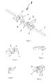
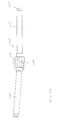
Figure 1 is an exploded perspective view of the hinge of one embodiment of the present invention; -
Figure 2 is a front view of the hinge ofFigure 1 without attachment means; -
Figure 3 is a top view of the hinge ofFigure 2 ; -
Figure 4 is a side elevation view of the hinge ofFigure 2 ; -
Figure 5 is a perspective view of the hinge ofFigure 2 ; -
Figure 6 is a perspective view of the hinge ofFigure 2 with the hinge element in a second position; -
Figure 7 is a perspective view of the hinge ofFigure 2 with the collar in a second position; -
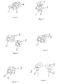
Figure 8 is an exploded perspective view of the hinge ofFigure 1 ; -
Figure 9 is a perspective view of the hinge ofFigure 8 in a first position; -
Figure 10 is a perspective view of the hinge ofFigure 8 in a second position; -
Figure 11 is a side exploded view of the hinge ofFigure 8 ; -
Figure 12 is a side view of the hinge ofFigure 8 in a first position; -
Figure 13 is a side view of the hinge ofFigure 8 in a second position; -
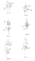
Figure 14 is a cross-sectional exploded side view of a hinge element of a second embodiment of the invention; -
Figure 15 is a cross-sectional side view of the hinge ofFigure 14 ; -
Figure 16 is an exploded front view of the hinge ofFigure 14 ; -
Figure 17 is a front view of the hinge ofFigure 14 ; -
Figure 18 is an exploded perspective view of the hinge ofFigure 14 ; -
Figure 19 is an exploded perspective view of the hinge ofFigure 14 ; -
Figure 20 is a perspective view of the hinge ofFigure 14 ; -
Figure 21 is a perspective view of the hinge ofFigure 14 ; -
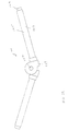
Figure 22 is a perspective view of the hinge of one embodiment of the present invention in use; -
Figure 23 is a perspective view of the hinge ofFigure 22 in use in a second position; -
Figure 24 is a perspective view of the hinge ofFigure 22 in use in a third position; -
Figure 25 is a perspective view of the hinge ofFigure 22 in use in a fourth position; -
Figure 26 is a cross-sectional top view of an embodiment of the hinge in locked position in use; -
Figure 27 is a cross sectional bottom view of the hinge ofFigure 26 ; -
Figure 28 is a perspective view of a second embodiment of a hinge; -
Figure 29 is a front view of the hinge ofFigure 28 ; -
Figure 30 is an end view of the hinge ofFigure 28 ; -
Figure 31 is a perspective view of the hinge ofFigure 28 ; -
Figure 32 is a top perspective view of the hinge ofFigure 28 ; and, -
Figure 33 is a perspective end view of the hinge ofFigure 28 . - Referring to the figures, there is shown a
hinge 1 for allowing a relative motion between two solid articles. In the embodiment shown in the figures the solid articles are in the form of twochess board halves 30. - The
hinge 1 comprises twopivoting elements 3. Each of the twoindependent pivoting elements 3 is attached to ahinge pin 4 such that at least one of the two independent pivoting elements is rotatable about thehinge pin 4. The twoindependent pivoting elements 3 are therefore rotatable in respect of one another. - Each of the two
pivoting elements 3 further comprise a rotatable attachment means includingconnector 5,shaft 6 andcollar 11. - The two
pivoting elements 3 are moveable with respect to one another. As aresult articles 30 attached with thepivoting elements 3 are moveable with respect to one another. - The
connectors 5 are adapted to be fitted into the twosolid articles 30, such that the twosolid articles 30 extend outwardly from theconnectors 5. As seen inFigures 22 through 25 , in this form movement of thepivoting elements 3 brings the twosolid articles 30 from a parallel and adjacent position as shown inFigure 22 to a colinear position as shown inFigure 25 . - The
shaft 6 adds strength and length to thehinge 1 to bear the load of thesolid articles 30 beyond thepivoting elements 3. - Each
hinge collar 11 is adapted to be rotatably attached withconnector 5.Shaft 6 is provided with a screw thread or other means to engage withconnector 5. Hingecollar 11 is positioned aboutshaft 6 orconnector 5. Thehinge 1 andconnectors 5 can thus rotate with respect to thecollars 11. Thecollars 11 are shaped to curve over the hinge element but can be any shape. - As shown in
figures 26 and 27 , thehinge collar 11 is attached to thesolid articles 30 by way of set screws or other attachment means 26 and 27. Eachshaft 6 sits in abearing tube 7 inset into eachsolid article 30.Shaft 6 is able to rotate in bearingtube 7. Thehinge 1 and theconnectors 5 are thus rotatable with respect to thesolid articles 30 about the axis of theshafts 6. - The
hinge 1 is rotatable such that the direction of freedom of movement of thepivoting elements 3 with respect to thesolid articles 30 is changed. This change in the direction of freedom of movement of thepivoting elements 3 with respect to thesolid articles 30 allows thesolid articles 30 to move in varying planes with respect to one another. - In effect, the pivoting
elements 3 move such that thehinge pin 4 acts as an axis of rotation. When thehinge 1 is rotated through 90 degrees, thehinge pin 4 and the pivoting elements' 3 axis of rotation is rotated through 90 degrees. As a result the freedom of movement of the hinge is shifted through 90 degrees. Depending upon the size and shape of thesolid articles 30 this results in the solid articles being moveable with respect to one another in a different plane or, in certain circumstances means thehinge 1 and pivotingelements 3 are locked so that thesolid articles 30 cannot move with respect to one another. That is thehinge 1 is in a locked position. - The locked and unlocked hinge positions are best shown in use in a flat solid article such as two chess board halves. This is best shown in
figures 22 through 25 . - In the locked position shown in
Figure 25 , the orientation of thehinge 1 with respect to thesolid articles 30 restricts the movement of thepivoting elements 3 with respect to one another. In the locked position the axis of rotation of thepivoting elements 3 is perpendicular to the only available axis of rotation of thesolid articles 30. As a result thesolid articles 30 are fixed in position in relation to one another. - The
collar 10 is attached to or set into thearticles 30 being hinged. Eachcollar piece 11 is inset on one side of the hinge joint 15 extending between thearticles 30. Because thecollar 10 is set into the twoarticles 30 thehinge 1 can be flush with thearticles 30. - In use, in order to unlock the
hinge 1, a user rotates thehinge 1 with respect to thearticles 30. This rotates theconnectors 5 and connectingshafts 6 in relation to thearticles 30. Thecollar 11, on the other hand, is fixed with respect to thearticles 30. Thehinge element 2 can be rotated with respect to thearticles 30. - The hinge can be rotated 90 degrees. A ridge 15 associated with the
connectors 5 and aninset portion 16 associated with the collar interact to stop thehinge 1 from rotating an angle greater than 90 degrees. - In other forms the hinge can be rotated through up to 360 degrees by incorporating a ridge which interacts to stop the hinge from rotating more than 180 degrees, 270 degrees or any angle. When no ridge is incorporated the hinge can be rotated 360 degrees. When the hinge can be rotated through 360 degrees the direction of freedom of movement can be rotated through 360 degrees, allowing the
solid articles 30 to move in varying planes with respect to one another. - In use, the position of the
hinge 1 in the hinged article and the opening movement of thehinge 1 prevents the meeting of thearticles 30 joined by thehinge 1 along the hinge joint 15. There is therefore no crunching or grinding or opportunity of wear between chess board halves along the hinge joint 15. - Further, the
hinge 1 allows for no hyperextension beyond the position determined as the home position. When theconnectors 5 are collinear to one another thepivoting elements 3 meet to prevent hyperextension of thehinge 1. - The
collar 11 andhinge element 2 allows for staged fitting, whereby thecollar 11 is attached to the hinged article. Subsequently the hinge element is attached. - The
hinge element 2 is composed of metal, plastic or any other rigid durable substance. - In another embodiment, the centre of gravity of the hinge element is positioned such that gravity is utilised to automate the rotation of the
hinge element 2 within the collar. In another form the rotation of the hinge is actuated automatically by a motor, spring, magnet or other external means. - In the embodiment described above, the two
solid articles 30 comprise chess board halves. In other embodiments the twosolid articles 30 may comprise any two solid articles requiring movement in respect to one another, for example scaffolding, flooring, two panels of an articulated dividing screen, a board game board, cupboard doors, and advertising panels. - Referring to
Figures 28 - 33 , disclosed is a further embodiment of ahinge 100 of the present disclosure. In this illustrated form thehinge 100 comprises two pivotingelements 103. Each of the twoindependent pivoting elements 103 is engaged with ahinge pin 104 such that at least one of the two independent pivoting elements is rotatable about thehinge pin 104. The twoindependent pivoting elements 103 are therefore hingedly rotatable in respect of one another. - In the illustrated form, each of the two pivoting
elements 103 further comprise ashaft 106 extending therefrom. Theshaft 106 is fixed with respect to the pivotingelement 103. In alternative forms the shaft may take another shape. Arotatable attachment element 105 is engaged with theshaft 106. In the illustrated form the attachment element is in the form of acylindrical tube 107 shaped to engage the shaft by being positioned about theshaft 106. - The attachment means 105 are, in some forms, adapted to be fitted to two sections of an article such that the two sections are hinged with respect to one another. The
shaft 106 adds strength and length to thehinge 100 to bear the load of the sections of the article. However, in alternative forms the shafts are shaped differently but allow for an attachment element to be rotatably or slideably attached thereto. - The pivoting
elements 103 are therefore rotatable with respect to articles which are engaged with the attachment elements. - Rotation of pivoting
elements 103 with respect to the articles changes the hinge moment or the direction of hinge movement with respect to the article. This change in the direction of freedom of movement of the pivotingelements 103 allows the articles to move in varying planes with respect to one another or alternatively allows for locking of the hing when the hinge moment is aligned with an axis extending perpendicular or at an angle to the articles rather than aligning with the articles. - In effect, the pivoting
elements 103 move such that thehinge pin 104 acts as an axis of rotation. When the pivotingelements 103 are rotated through 90 degrees, thehinge pin 104 and the pivoting elements' 3 axis of rotation is rotated through 90 degrees. As a result the freedom of movement of the hinge is shifted through 90 degrees. Depending upon the size and shape of the articles this results in the articles being moveable with respect to one another in a different plane or, in certain circumstances means pivotingelements 103 are locked into position with respect to one another so that the solid articles cannot move with respect to one another. That is thehinge 1 is in a locked position. - In use, in order to unlock the
hinge 1, a user rotates the pivotingelements 103 andhinge pin 104 1 with respect to the articles. This rotates theshafts 106 with respect to the articles while theattachments elements 105 remain fixed with respect to the articles. - In this and other forms the pivoting elements can be rotated through up to 360 degrees When the hinge can be rotated through 360 degrees the direction of freedom of movement can be rotated through 360 degrees, allowing the
solid articles 30 to move in varying planes with respect to one another. - The
hinge 100 is composed of metal, plastic or any other rigid durable substance. - The
hinge 100 in the illustrated form allows for the hinge to be opened automatically without direct rotational contact with the pivoting elements. Pressure by a user against the hinge allows rotation of the hinge moment with respect to the articles and the attachment elements allowing for a shift in hinge moment without a user manually contacting the pivotingelements 103. This configuration can in turn allow for automatic unlocking of the hinge in, for example, a door.
Claims (7)
- A hinge comprising two pivoting elements, each pivoting element including a hinge element and an attachment means for attaching the hinge element to an article such that when the pivoting elements are attached to the article the hinge element is rotatable with respect to the article, the attachment means comprising a connector which, in use, extends into the article and is surrounded by the article, the connector being rotatably engaged with the article to allow rotation of the hinge element with respect to the article, the rotation of the hinge with respect to the article effecting a change in the direction of freedom of movement of the hinge.
- A hinge as defined in claim 1, wherein the hinge further comprises a hinge pin.
- A hinge as defined in claim 1, wherein the attachment means comprises a hinge collar adapted to be attached to one of the two articles and the hinge element is rotatable with respect to the hinge collar.
- A hinge as defined in claim 2, wherein the attachment means comprises a hinge collar adapted to be attached to one of the two articles and the hinge element is rotatable with respect to the hinge collar.
- A hinge as defined in any one of the preceding claims, wherein the axis of rotation of the pivoting elements with respect to one another and the axis of rotation of the hinge element with respect to the articles are perpendicular to one another.
- A hinge as defined in any one of the preceding claims, wherein the connector comprises a shaft extending from each pivoting element.
- A hinge as defined in any one of the preceding claims, wherein rotation of the hinge element moves the hinge between a locked position and an unlocked position.
Applications Claiming Priority (1)
| Application Number | Priority Date | Filing Date | Title |
|---|---|---|---|
| US13/153,978 US8875349B2 (en) | 2005-06-30 | 2011-06-06 | Hinge |
Publications (1)
| Publication Number | Publication Date |
|---|---|
| EP2532817A1 true EP2532817A1 (en) | 2012-12-12 |
Family
ID=46207900
Family Applications (1)
| Application Number | Title | Priority Date | Filing Date |
|---|---|---|---|
| EP12171050A Withdrawn EP2532817A1 (en) | 2011-06-06 | 2012-06-06 | Hinge |
Country Status (2)
| Country | Link |
|---|---|
| EP (1) | EP2532817A1 (en) |
| AU (1) | AU2011254253A1 (en) |
Families Citing this family (1)
| Publication number | Priority date | Publication date | Assignee | Title |
|---|---|---|---|---|
| CN120061658B (en) * | 2025-04-25 | 2025-06-20 | 佛山市凯锐德金属制品有限公司 | A kind of begonia corner hinge |
Citations (2)
| Publication number | Priority date | Publication date | Assignee | Title |
|---|---|---|---|---|
| US4111574A (en) * | 1973-09-17 | 1978-09-05 | Runyon John F | Hinge joint assembly |
| WO2007002998A1 (en) * | 2005-06-30 | 2007-01-11 | Rolling Hinge Pty Limited | Hinge |
-
2011
- 2011-12-16 AU AU2011254253A patent/AU2011254253A1/en not_active Abandoned
-
2012
- 2012-06-06 EP EP12171050A patent/EP2532817A1/en not_active Withdrawn
Patent Citations (2)
| Publication number | Priority date | Publication date | Assignee | Title |
|---|---|---|---|---|
| US4111574A (en) * | 1973-09-17 | 1978-09-05 | Runyon John F | Hinge joint assembly |
| WO2007002998A1 (en) * | 2005-06-30 | 2007-01-11 | Rolling Hinge Pty Limited | Hinge |
Also Published As
| Publication number | Publication date |
|---|---|
| AU2011254253A1 (en) | 2012-01-19 |
Similar Documents
| Publication | Publication Date | Title |
|---|---|---|
| US8875349B2 (en) | Hinge | |
| US8359709B2 (en) | Locking hinge assembly | |
| AU2014317826B2 (en) | Apparatus for connecting door closer or operator to swing door | |
| CN101115899B (en) | Snap-type locking device | |
| KR20070033472A (en) | 2-axis swivel joint | |
| TW201738453A (en) | Hinge with elastic opening means for door leaves of furniture | |
| CN108697238A (en) | For the connection of the compact of furniture and the component of household items and leveling system | |
| US20120124776A1 (en) | Adjustable door stop with hinge pin | |
| AU2013373963A1 (en) | Thick plate type joint lock for ladder connection | |
| US8904836B2 (en) | Handle fixing mechanisms and methods of making and using thereof | |
| US7963002B2 (en) | Hinge | |
| AU2011254253A1 (en) | Hinge | |
| AU2006265768B2 (en) | Hinge | |
| AU2017245282A1 (en) | Hinge | |
| CN109790718A (en) | Awning | |
| CN105102746A (en) | Hinge pin for a hinge or joint | |
| US20120063840A1 (en) | Friction Ball Joint | |
| JP2015059310A5 (en) | ||
| CN213774855U (en) | Door lock structure | |
| TWI597430B (en) | Dust-proof spin-down safety hooks | |
| CN101772611A (en) | Hinge structure for the articulation of a tiltable shutter to a load-bearing side wall of the body of a furniture piece | |
| EP2212496B1 (en) | Improved rototranslation mechanism of a shutter of a containment element | |
| PL67318Y1 (en) | Coupling shaft | |
| KR102504079B1 (en) | Hinge structure for folding door and folding door system including the same | |
| CN204553531U (en) | A kind of hinge structure of children's safety fence |
Legal Events
| Date | Code | Title | Description |
|---|---|---|---|
| PUAI | Public reference made under article 153(3) epc to a published international application that has entered the european phase |
Free format text: ORIGINAL CODE: 0009012 |
|
| AK | Designated contracting states |
Kind code of ref document: A1 Designated state(s): AL AT BE BG CH CY CZ DE DK EE ES FI FR GB GR HR HU IE IS IT LI LT LU LV MC MK MT NL NO PL PT RO RS SE SI SK SM TR |
|
| AX | Request for extension of the european patent |
Extension state: BA ME |
|
| 17P | Request for examination filed |
Effective date: 20130612 |
|
| RBV | Designated contracting states (corrected) |
Designated state(s): AL AT BE BG CH CY CZ DE DK EE ES FI FR GB GR HR HU IE IS IT LI LT LU LV MC MK MT NL NO PL PT RO RS SE SI SK SM TR |
|
| 17Q | First examination report despatched |
Effective date: 20131203 |
|
| STAA | Information on the status of an ep patent application or granted ep patent |
Free format text: STATUS: THE APPLICATION IS DEEMED TO BE WITHDRAWN |
|
| 18D | Application deemed to be withdrawn |
Effective date: 20140614 |