EP2532484A2 - Handle assembly for power tool - Google Patents
Handle assembly for power tool Download PDFInfo
- Publication number
- EP2532484A2 EP2532484A2 EP12168921A EP12168921A EP2532484A2 EP 2532484 A2 EP2532484 A2 EP 2532484A2 EP 12168921 A EP12168921 A EP 12168921A EP 12168921 A EP12168921 A EP 12168921A EP 2532484 A2 EP2532484 A2 EP 2532484A2
- Authority
- EP
- European Patent Office
- Prior art keywords
- handle
- support member
- mounting portion
- assembly according
- resilient
- Prior art date
- Legal status (The legal status is an assumption and is not a legal conclusion. Google has not performed a legal analysis and makes no representation as to the accuracy of the status listed.)
- Granted
Links
Images

Classifications
-
- B—PERFORMING OPERATIONS; TRANSPORTING
- B25—HAND TOOLS; PORTABLE POWER-DRIVEN TOOLS; MANIPULATORS
- B25D—PERCUSSIVE TOOLS
- B25D17/00—Details of, or accessories for, portable power-driven percussive tools
- B25D17/04—Handles; Handle mountings
- B25D17/043—Handles resiliently mounted relative to the hammer housing
-
- B—PERFORMING OPERATIONS; TRANSPORTING
- B25—HAND TOOLS; PORTABLE POWER-DRIVEN TOOLS; MANIPULATORS
- B25F—COMBINATION OR MULTI-PURPOSE TOOLS NOT OTHERWISE PROVIDED FOR; DETAILS OR COMPONENTS OF PORTABLE POWER-DRIVEN TOOLS NOT PARTICULARLY RELATED TO THE OPERATIONS PERFORMED AND NOT OTHERWISE PROVIDED FOR
- B25F5/00—Details or components of portable power-driven tools not particularly related to the operations performed and not otherwise provided for
- B25F5/006—Vibration damping means
-
- B—PERFORMING OPERATIONS; TRANSPORTING
- B25—HAND TOOLS; PORTABLE POWER-DRIVEN TOOLS; MANIPULATORS
- B25F—COMBINATION OR MULTI-PURPOSE TOOLS NOT OTHERWISE PROVIDED FOR; DETAILS OR COMPONENTS OF PORTABLE POWER-DRIVEN TOOLS NOT PARTICULARLY RELATED TO THE OPERATIONS PERFORMED AND NOT OTHERWISE PROVIDED FOR
- B25F5/00—Details or components of portable power-driven tools not particularly related to the operations performed and not otherwise provided for
- B25F5/02—Construction of casings, bodies or handles
- B25F5/025—Construction of casings, bodies or handles with torque reaction bars for rotary tools
- B25F5/026—Construction of casings, bodies or handles with torque reaction bars for rotary tools in the form of an auxiliary handle
-
- B—PERFORMING OPERATIONS; TRANSPORTING
- B25—HAND TOOLS; PORTABLE POWER-DRIVEN TOOLS; MANIPULATORS
- B25D—PERCUSSIVE TOOLS
- B25D2222/00—Materials of the tool or the workpiece
- B25D2222/54—Plastics
- B25D2222/57—Elastomers, e.g. rubber
-
- B—PERFORMING OPERATIONS; TRANSPORTING
- B25—HAND TOOLS; PORTABLE POWER-DRIVEN TOOLS; MANIPULATORS
- B25D—PERCUSSIVE TOOLS
- B25D2250/00—General details of portable percussive tools; Components used in portable percussive tools
- B25D2250/371—Use of springs
-
- B—PERFORMING OPERATIONS; TRANSPORTING
- B25—HAND TOOLS; PORTABLE POWER-DRIVEN TOOLS; MANIPULATORS
- B25D—PERCUSSIVE TOOLS
- B25D2250/00—General details of portable percussive tools; Components used in portable percussive tools
- B25D2250/371—Use of springs
- B25D2250/381—Leaf springs
Definitions
- the present invention relates to a handle assembly for a power tool, and relates particularly, but not exclusively, to a vibration damping handle assembly for use with a hammer power drill.
- DE 102009000598 discloses a supplementary handle for a hammer power drill having a vibration damping arrangement comprising a torsion spring provided at each axial end of a mount for the handle.
- Preferred embodiments of the present invention seek to overcome one or more of the above disadvantages of the prior art.
- a handle assembly for a power tool comprising:-
- a vibration damping mechanism comprising at least one elongate biasing member having at least one respective resilient portion extending without coiling thereof from said first mounting portion to said second mounting portion and adapted to engage said third mounting portion such that pivoting of the handle relative to the support member causes deformation of said resilient portion causing said resilient portion to oppose said pivoting of the handle relative to the support member
- This provides the advantage of enabling simpler, more cost effective construction of the apparatus while enabling the apparatus to be more robust.
- the advantage is also provided of enabling greater control of the vibration damping properties over a wider range of handle positions.
- At least one said biasing member may comprise a respective resilient rod.
- the vibration damping mechanism may comprise a plurality of said rods.
- Each end of at least one said rod may be located in a respective recess in said first and second mounting portion and the rod may be adapted to engage at least one protrusion on said third mounting portion.
- the assembly may further comprise at least one fastener member for retaining said first mounting portion in position relative to said second mounting portion and extending along an axis of pivoting of said handle relative to said support member.
- the vibration damping mechanism may comprise at least one elongate resilient torsion member having a first part mounted to the third mounting portion and a respective second part mounted to each of said first and second mounting portions such that pivoting of the handle relative to the support member causes twisting of the torsion member to resiliently oppose pivoting of the handle relative to the support member.
- At least one said resilient torsion member may comprise at least one respective resilient sheet material.
- This provides the advantage of enabling simpler construction of the resilient member by enabling it to be formed by stamping.
- At least one said resilient torsion member may further comprise at least one enlarged portion adapted to be mounted to the support member and/or at least one mounting portion by means of screws.
- This provides the advantage of enabling stresses applied to the resilient member to be spread over a larger surface area, thereby making the device more robust.
- the handle and support member may be adapted to form a loop.
- the apparatus may further comprise at least one limiting device for limiting pivoting movement of the handle relative to the support member.
- At least one said limiting device may include at least one respective abutment member on the handle and/or the support member.
- a handle assembly 2 for mounting a handle 4 to a forward part of a housing (not shown) of a power tool such as a hammer drill comprises a support member comprising a base 6 of durable plastics material having a generally partially cylindrical part 8 for abutting the housing of the power tool, and a flexible metal strap 10 which wraps around the housing to retain the base 6 in position on the housing.
- the strap 10 is tightened or slackened by means of a rotatable knob 12.
- the handle 4 has a grip 14 of suitable plastics material and first and second mounting parts 16 pivotably attached to the base 6 by means of a torsion spring 18 ( Figures 5 and 6 ).
- the torsion spring 18 comprises a flat sheet of resilient metal such as steel having a central enlarged portion 20 and enlarged portions 22 at its ends.
- the mounting parts 16 of the handle 4 are pivotably mounted to a third mounting part 24 on the base 6 such that the enlarged portions 22 of the torsion spring 18 are received in respective first and second mounting parts 16.
- the enlarged portions 22 of the torsion spring 18 are attached to the first and second mounting parts 16 by means of screws 26, and the enlarged portion 20 at the centre of the torsion spring 18 is attached to the third mounting part 24 by means of a screw (not shown).
- the ends of the first and second mounting parts 16 are closed by end caps 28 which are slidably received in respective apertures in the mounting parts 16.
- the torsion spring 18 When no load is applied to the grip 14, the torsion spring 18 remains flat and the grip 14 remains in its rest position. However, when pressure is applied to the grip 14, the mounting parts 16 at the respective ends of the grip 14 cause the enlarged portions 22 at the ends of the torsion spring 18 to twist around the longitudinal axis of the torsion spring 18 relative to the enlarged portion 20 at the centre of the torsion spring 18, and twisting movement of the torsion spring 18 damps the transmission of vibrations from the body of the power tool via the base 6 to the grip 14.
- the clamping mechanism 30 includes a pair of wedges 32 of triangular cross section which are attached to respective ends of the metal strap 10.
- the wedges 32 are located in respective recesses 34 in the base 6, the length of the recess 34 in a direction transverse to the pivot axis 36 of the grip 14 being longer than the wedge 32.
- a gap 38 is provided between the end of the recess 34 and the end of the wedge 32, and each wedge 32 is slidable relative to the base 6 by means of inclined surfaces 40 on the base 6.
- Each wedge 32 is provided with an aperture 42 through which a bolt 44 passes, the bolt 44 extending from a head 46 which non-rotatably engages the external surface of the base 6, through the wedges 32 and through an aperture 50 through the base 6, and engages an internal bore 48 in the rotatable knob 12 by means of mutually engaging screw threads on the end of the bolt 44 and the internal bore 48 of the knob 12.
- Rotation of the knob 12 in a first direction causes the knob 12 to move axially along the bolt 44, urging the wedges 32 towards each other.
- the wedges 32 slide along the inclined surfaces 40 on the base 6 and move away from the part cylindrical support 8 on the base 6.
- the aperture 50 through the base 6 has an elongated cross section, such as an oval shape, to accommodate movement of the bolt 44 in a transverse direction relative to the axis 36 of rotation of the grip 14. Rotation of the knob 12 in the opposite direction enables the wedges 32 to be moved in an opposite direction relative to the base 6 to loosen the strap 10 around the housing of the tool to enable the position of the handle 4 to be adjusted.
- FIGS 7 to 10 show a second embodiment of a handle assembly of the present invention, in which parts common to the embodiment of Figures 1 to 6 are denoted by like reference numerals but increased by 100.
- the torsion spring 18 of the embodiment of Figures 1 to 6 is replaced by a pair of spring rods 118 located parallel to and spaced from pivot axis 160 of handle 104 relative to base 106.
- Each end of the spring rods 118 is located in a respective recess 162 of a side handle cap 128 and engages a protrusion 164 in the side handle base 106.
- the side handle caps 128 are held in position by means of a threaded rod 166 extending along the pivot axis 160 and a cap nut 168 being located at each end of the threaded rod 166 in a respective recess 170 in the side handle cap 128.
- the spring rods 118 are bent as a result of the change in circumferential position of the recesses 162 at the ends of the rods 118 relative to the protrusions 164 between the ends of the rods 118, and the resilience of the spring rods 118 resists this pivoting motion and damps vibrations passing from the tool housing to the handle 104.
Landscapes
- Engineering & Computer Science (AREA)
- Mechanical Engineering (AREA)
- Percussive Tools And Related Accessories (AREA)
- Scissors And Nippers (AREA)
Abstract
Description
- The present invention relates to a handle assembly for a power tool, and relates particularly, but not exclusively, to a vibration damping handle assembly for use with a hammer power drill.
-
DE 102009000598 discloses a supplementary handle for a hammer power drill having a vibration damping arrangement comprising a torsion spring provided at each axial end of a mount for the handle. - This arrangement suffers from the drawback that the torsion springs must be highly robust, thereby increasing the cost of manufacture of the apparatus, and it is difficult to control the flexibility of the spring over a wide range of handle positions.
- Preferred embodiments of the present invention seek to overcome one or more of the above disadvantages of the prior art.
- According to the present invention, there is provided a handle assembly for a power tool, the handle assembly comprising:-
- a support member adapted to be mounted to a body of a power tool for supporting a handle on the power tool;
- a handle adapted to be pivotably mounted to the support member, wherein first and second mounting portions on one of the handle and the support member are pivotably mounted to respective ends of a third mounting portion on the other of the handle and the support member; and
- a vibration damping mechanism comprising at least one elongate biasing member having at least one respective resilient portion extending without coiling thereof from said first mounting portion to said second mounting portion and adapted to engage said third mounting portion such that pivoting of the handle relative to the support member causes deformation of said resilient portion causing said resilient portion to oppose said pivoting of the handle relative to the support member.
- By providing a vibration damping mechanism comprising at least one elongate biasing member having at least one respective resilient portion extending without coiling thereof from said first mounting portion to said second mounting portion and adapted to engage said third mounting portion such that pivoting of the handle relative to the support member causes deformation of said resilient portion causing said resilient portion to oppose said pivoting of the handle relative to the support member, this provides the advantage of enabling simpler, more cost effective construction of the apparatus while enabling the apparatus to be more robust. The advantage is also provided of enabling greater control of the vibration damping properties over a wider range of handle positions.
- At least one said biasing member may comprise a respective resilient rod.
- This provides the advantage of making the assembly more robust in construction.
- The vibration damping mechanism may comprise a plurality of said rods.
- Each end of at least one said rod may be located in a respective recess in said first and second mounting portion and the rod may be adapted to engage at least one protrusion on said third mounting portion.
- The assembly may further comprise at least one fastener member for retaining said first mounting portion in position relative to said second mounting portion and extending along an axis of pivoting of said handle relative to said support member.
- The vibration damping mechanism may comprise at least one elongate resilient torsion member having a first part mounted to the third mounting portion and a respective second part mounted to each of said first and second mounting portions such that pivoting of the handle relative to the support member causes twisting of the torsion member to resiliently oppose pivoting of the handle relative to the support member.
- At least one said resilient torsion member may comprise at least one respective resilient sheet material.
- This provides the advantage of enabling simpler construction of the resilient member by enabling it to be formed by stamping.
- At least one said resilient torsion member may further comprise at least one enlarged portion adapted to be mounted to the support member and/or at least one mounting portion by means of screws.
- This provides the advantage of enabling stresses applied to the resilient member to be spread over a larger surface area, thereby making the device more robust.
- The handle and support member may be adapted to form a loop.
- The apparatus may further comprise at least one limiting device for limiting pivoting movement of the handle relative to the support member.
- At least one said limiting device may include at least one respective abutment member on the handle and/or the support member.
- Preferred embodiments of the invention will now be described, by way of example only and not in any limitative sense, with reference to the accompanying drawings, in which:
-
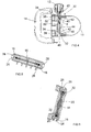
Figure 1 is a perspective view of a handle assembly of a first embodiment of the present invention; -
Figure 2 is a top view of the assembly ofFigure 1 ; -
Figure 3 is a side view of the assembly ofFigure 1 ; -
Figure 4 is a cross sectional view along the line A-A inFigure 3 ; -
Figure 5 is a cross sectional view along the line C-C inFigure 3 ; -
Figure 6 is a cross sectional view along the line B-B inFigure 3 ; -
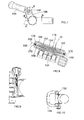
Figure 7 is a side view of a handle assembly of a second embodiment of the present invention; -
Figure 8 is a cross sectional view along the line A-A inFigure 7 ; -
Figure 9 is a cross sectional view along the line B-B inFigure 7 ; and -
Figure 10 is a top view of the assembly ofFigure 7 . - Referring to
Figures 1 to 6 , ahandle assembly 2 for mounting ahandle 4 to a forward part of a housing (not shown) of a power tool such as a hammer drill comprises a support member comprising abase 6 of durable plastics material having a generally partiallycylindrical part 8 for abutting the housing of the power tool, and aflexible metal strap 10 which wraps around the housing to retain thebase 6 in position on the housing. Thestrap 10 is tightened or slackened by means of arotatable knob 12. Thehandle 4 has agrip 14 of suitable plastics material and first andsecond mounting parts 16 pivotably attached to thebase 6 by means of a torsion spring 18 (Figures 5 and 6 ). Thetorsion spring 18 comprises a flat sheet of resilient metal such as steel having a central enlargedportion 20 and enlargedportions 22 at its ends. - The
mounting parts 16 of thehandle 4 are pivotably mounted to a third mountingpart 24 on thebase 6 such that the enlargedportions 22 of thetorsion spring 18 are received in respective first andsecond mounting parts 16. The enlargedportions 22 of thetorsion spring 18 are attached to the first andsecond mounting parts 16 by means ofscrews 26, and the enlargedportion 20 at the centre of thetorsion spring 18 is attached to the third mountingpart 24 by means of a screw (not shown). The ends of the first andsecond mounting parts 16 are closed byend caps 28 which are slidably received in respective apertures in themounting parts 16. - When no load is applied to the
grip 14, thetorsion spring 18 remains flat and thegrip 14 remains in its rest position. However, when pressure is applied to thegrip 14, themounting parts 16 at the respective ends of thegrip 14 cause the enlargedportions 22 at the ends of thetorsion spring 18 to twist around the longitudinal axis of thetorsion spring 18 relative to the enlargedportion 20 at the centre of thetorsion spring 18, and twisting movement of thetorsion spring 18 damps the transmission of vibrations from the body of the power tool via thebase 6 to thegrip 14. - Referring now to
Figure 4 , aclamping mechanism 30 for mounting thebase 6 to the housing of the power tool is shown in greater detail. Theclamping mechanism 30 includes a pair ofwedges 32 of triangular cross section which are attached to respective ends of themetal strap 10. Thewedges 32 are located inrespective recesses 34 in thebase 6, the length of therecess 34 in a direction transverse to thepivot axis 36 of thegrip 14 being longer than thewedge 32. As a result, agap 38 is provided between the end of therecess 34 and the end of thewedge 32, and eachwedge 32 is slidable relative to thebase 6 by means ofinclined surfaces 40 on thebase 6. Eachwedge 32 is provided with anaperture 42 through which abolt 44 passes, thebolt 44 extending from ahead 46 which non-rotatably engages the external surface of thebase 6, through thewedges 32 and through anaperture 50 through thebase 6, and engages aninternal bore 48 in therotatable knob 12 by means of mutually engaging screw threads on the end of thebolt 44 and theinternal bore 48 of theknob 12. Rotation of theknob 12 in a first direction causes theknob 12 to move axially along thebolt 44, urging thewedges 32 towards each other. As a result, thewedges 32 slide along theinclined surfaces 40 on thebase 6 and move away from the partcylindrical support 8 on thebase 6. This draws the ends of themetal strap 10 with thewedges 32 into thebase 6, as a result of which the length of thestrap 10 is shortened and thestrap 10 is tightened around the housing of the power tool to clamp thehandle 4 in position relative to the housing. Theaperture 50 through thebase 6 has an elongated cross section, such as an oval shape, to accommodate movement of thebolt 44 in a transverse direction relative to theaxis 36 of rotation of thegrip 14. Rotation of theknob 12 in the opposite direction enables thewedges 32 to be moved in an opposite direction relative to thebase 6 to loosen thestrap 10 around the housing of the tool to enable the position of thehandle 4 to be adjusted. -
Figures 7 to 10 show a second embodiment of a handle assembly of the present invention, in which parts common to the embodiment ofFigures 1 to 6 are denoted by like reference numerals but increased by 100. - In the embodiment of
Figures 7 to 10 , thetorsion spring 18 of the embodiment ofFigures 1 to 6 is replaced by a pair ofspring rods 118 located parallel to and spaced frompivot axis 160 ofhandle 104 relative tobase 106. Each end of thespring rods 118 is located in arespective recess 162 of aside handle cap 128 and engages aprotrusion 164 in theside handle base 106. Theside handle caps 128 are held in position by means of a threadedrod 166 extending along thepivot axis 160 and acap nut 168 being located at each end of the threadedrod 166 in arespective recess 170 in theside handle cap 128. - As the
side handle 104 is pivoted about thepivot axis 160 relative to thebase 106, thespring rods 118 are bent as a result of the change in circumferential position of therecesses 162 at the ends of therods 118 relative to theprotrusions 164 between the ends of therods 118, and the resilience of thespring rods 118 resists this pivoting motion and damps vibrations passing from the tool housing to thehandle 104. - It will be appreciated by persons skilled in the art that the above embodiment has been described by way of example only and not in any limitative sense, and that various alterations and modifications are possible without departure from the scope of the invention as defined by the appended claims. For example, it is possible to replace the threaded
rod 166 of the embodiment ofFigures 7 to 10 by a rod having a single screw thread and asingle cap nut 168 at one end.
Claims (11)
- A handle assembly for a power tool, the handle assembly comprising:-
a support member adapted to be mounted to a body of a power tool for supporting a handle on the power tool;
a handle adapted to be pivotably mounted to the support member, wherein first and second mounting portions on one of the handle and the support member are pivotably mounted to respective ends of a third mounting portion on the other of the handle and the support member; and
a vibration damping mechanism comprising at least one elongate biasing member having at least one respective resilient portion extending without coiling thereof from said first mounting portion to said second mounting portion and adapted to engage said third mounting portion such that pivoting of the handle relative to the support member causes deformation of said resilient portion causing said resilient portion to oppose said pivoting of the handle relative to the support member. - An assembly according to claim 1, wherein at least one said biasing member comprises a respective resilient rod.
- An assembly according to claim 2, wherein the vibration damping mechanism comprises a plurality of said rods.
- An assembly according to claim 2 or 3, wherein each end of at least one said rod is located in a respective recess in said first and second mounting portion and the rod is adapted to engage at least one protrusion on said third mounting portion.
- An assembly according to any one of the preceding claims, further comprising at least one fastener member for retaining said first mounting portion in position relative to said second mounting portion and extending along an axis of pivoting of said handle relative to said support member.
- An assembly according to any one of the preceding claims, wherein the vibration damping mechanism comprises at least one elongate resilient torsion member having a first part mounted to the third mounting portion and a respective second part mounted to each of said first and second mounting portions such that pivoting of the handle relative to the support member causes twisting of the torsion member to resiliently oppose pivoting of the handle relative to the support member.
- An assembly according to claim 6, wherein at least one said resilient torsion member comprises at least one respective resilient sheet material.
- An assembly according to claim 6 or 7, wherein at least one said resilient torsion member further comprises at least one enlarged portion adapted to be mounted to the base portion and/or at least one mounting portion by means of screws.
- An assembly according to any one of the preceding claims, wherein the handle and support member are adapted to form a loop.
- An assembly according to any one of the preceding claims, further comprising at least one limiting device for limiting pivoting movement of the handle relative to the support member.
- An assembly according to claim 10, wherein at least one said limiting device includes at least one respective abutment member on the handle and/or the support member.
Applications Claiming Priority (2)
| Application Number | Priority Date | Filing Date | Title |
|---|---|---|---|
| GB201109492A GB201109492D0 (en) | 2011-06-07 | 2011-06-07 | Handle assembly for power tool |
| GB201113116A GB201113116D0 (en) | 2011-07-29 | 2011-07-29 | Handle assembly for power tool |
Publications (3)
| Publication Number | Publication Date |
|---|---|
| EP2532484A2 true EP2532484A2 (en) | 2012-12-12 |
| EP2532484A3 EP2532484A3 (en) | 2013-05-08 |
| EP2532484B1 EP2532484B1 (en) | 2017-01-11 |
Family
ID=46149221
Family Applications (1)
| Application Number | Title | Priority Date | Filing Date |
|---|---|---|---|
| EP12168921.0A Active EP2532484B1 (en) | 2011-06-07 | 2012-05-22 | Handle assembly for power tool |
Country Status (1)
| Country | Link |
|---|---|
| EP (1) | EP2532484B1 (en) |
Citations (1)
| Publication number | Priority date | Publication date | Assignee | Title |
|---|---|---|---|---|
| DE102009000598A1 (en) | 2008-02-15 | 2009-08-20 | Robert Bosch Gmbh | Vibration-decoupled handle |
Family Cites Families (4)
| Publication number | Priority date | Publication date | Assignee | Title |
|---|---|---|---|---|
| US2629364A (en) * | 1950-06-16 | 1953-02-24 | Ingersoll Rand Co | Vibration absorbing handle for rock drills |
| EP0156387B1 (en) * | 1984-03-30 | 1990-11-07 | Makoto Minamidate | Vibration-proof grip device |
| DE102005000205A1 (en) * | 2005-12-23 | 2007-06-28 | Hilti Ag | Handle of a hand-held tool device |
| DE102005000202A1 (en) * | 2005-12-23 | 2007-06-28 | Hilti Ag | Handle with vibration reducing device |
-
2012
- 2012-05-22 EP EP12168921.0A patent/EP2532484B1/en active Active
Patent Citations (1)
| Publication number | Priority date | Publication date | Assignee | Title |
|---|---|---|---|---|
| DE102009000598A1 (en) | 2008-02-15 | 2009-08-20 | Robert Bosch Gmbh | Vibration-decoupled handle |
Also Published As
| Publication number | Publication date |
|---|---|
| EP2532484A3 (en) | 2013-05-08 |
| EP2532484B1 (en) | 2017-01-11 |
Similar Documents
| Publication | Publication Date | Title |
|---|---|---|
| US20120312572A1 (en) | Handle assembly for power tool | |
| US9180586B2 (en) | Handle assembly for power tool | |
| JP5662115B2 (en) | Steering device | |
| US10053890B2 (en) | Holder | |
| US9782834B2 (en) | Fixture | |
| EP2784335A1 (en) | A clamp assembly | |
| US20090194649A1 (en) | Adjustable supporting device for a display panel | |
| EP2407279B1 (en) | Side handle | |
| EP3187393B1 (en) | Steering column apparatus | |
| US7685904B2 (en) | Adjustable riser assembly | |
| CA2690038A1 (en) | Dynamic stabilization connecting member with pre-tensioned solid core | |
| JP2009227181A (en) | Steering device | |
| US20180071895A1 (en) | Hand clamp improvement and accessory | |
| US6905445B1 (en) | Resistance adjuster for adjusting a resistance-providing member on a stationary bicycle | |
| EP1800807A1 (en) | Vibration damping handle | |
| CN107921617A (en) | Lateral handle | |
| JP6866749B2 (en) | Rear cushion device | |
| EP2532484B1 (en) | Handle assembly for power tool | |
| JP4680617B2 (en) | Spring unit for vehicle suspension | |
| US7303240B2 (en) | Fitting structure of vehicle wheel cover | |
| US20100252373A1 (en) | Friction device for a spring cylinder | |
| JP2020516790A (en) | Device for guiding a wire in a wire binding machine and a wire binding machine including the device | |
| JP4555069B2 (en) | Aori stop | |
| US20210287637A1 (en) | Snare drum throw off | |
| JP4308634B2 (en) | 煽 Stopper |
Legal Events
| Date | Code | Title | Description |
|---|---|---|---|
| PUAI | Public reference made under article 153(3) epc to a published international application that has entered the european phase |
Free format text: ORIGINAL CODE: 0009012 |
|
| AK | Designated contracting states |
Kind code of ref document: A2 Designated state(s): AL AT BE BG CH CY CZ DE DK EE ES FI FR GB GR HR HU IE IS IT LI LT LU LV MC MK MT NL NO PL PT RO RS SE SI SK SM TR |
|
| AX | Request for extension of the european patent |
Extension state: BA ME |
|
| PUAL | Search report despatched |
Free format text: ORIGINAL CODE: 0009013 |
|
| AK | Designated contracting states |
Kind code of ref document: A3 Designated state(s): AL AT BE BG CH CY CZ DE DK EE ES FI FR GB GR HR HU IE IS IT LI LT LU LV MC MK MT NL NO PL PT RO RS SE SI SK SM TR |
|
| AX | Request for extension of the european patent |
Extension state: BA ME |
|
| RIC1 | Information provided on ipc code assigned before grant |
Ipc: B25F 5/02 20060101ALI20130404BHEP Ipc: B25D 17/04 20060101AFI20130404BHEP Ipc: B25F 5/00 20060101ALI20130404BHEP |
|
| 17P | Request for examination filed |
Effective date: 20130930 |
|
| RBV | Designated contracting states (corrected) |
Designated state(s): AL AT BE BG CH CY CZ DE DK EE ES FI FR GB GR HR HU IE IS IT LI LT LU LV MC MK MT NL NO PL PT RO RS SE SI SK SM TR |
|
| GRAP | Despatch of communication of intention to grant a patent |
Free format text: ORIGINAL CODE: EPIDOSNIGR1 |
|
| STAA | Information on the status of an ep patent application or granted ep patent |
Free format text: STATUS: GRANT OF PATENT IS INTENDED |
|
| GRAS | Grant fee paid |
Free format text: ORIGINAL CODE: EPIDOSNIGR3 |
|
| GRAA | (expected) grant |
Free format text: ORIGINAL CODE: 0009210 |
|
| STAA | Information on the status of an ep patent application or granted ep patent |
Free format text: STATUS: THE PATENT HAS BEEN GRANTED |
|
| INTG | Intention to grant announced |
Effective date: 20161114 |
|
| AK | Designated contracting states |
Kind code of ref document: B1 Designated state(s): AL AT BE BG CH CY CZ DE DK EE ES FI FR GB GR HR HU IE IS IT LI LT LU LV MC MK MT NL NO PL PT RO RS SE SI SK SM TR |
|
| REG | Reference to a national code |
Ref country code: GB Ref legal event code: FG4D |
|
| REG | Reference to a national code |
Ref country code: CH Ref legal event code: EP |
|
| REG | Reference to a national code |
Ref country code: AT Ref legal event code: REF Ref document number: 860825 Country of ref document: AT Kind code of ref document: T Effective date: 20170115 |
|
| REG | Reference to a national code |
Ref country code: IE Ref legal event code: FG4D |
|
| REG | Reference to a national code |
Ref country code: DE Ref legal event code: R096 Ref document number: 602012027634 Country of ref document: DE |
|
| REG | Reference to a national code |
Ref country code: LT Ref legal event code: MG4D |
|
| REG | Reference to a national code |
Ref country code: NL Ref legal event code: MP Effective date: 20170111 |
|
| REG | Reference to a national code |
Ref country code: AT Ref legal event code: MK05 Ref document number: 860825 Country of ref document: AT Kind code of ref document: T Effective date: 20170111 |
|
| PG25 | Lapsed in a contracting state [announced via postgrant information from national office to epo] |
Ref country code: NL Free format text: LAPSE BECAUSE OF FAILURE TO SUBMIT A TRANSLATION OF THE DESCRIPTION OR TO PAY THE FEE WITHIN THE PRESCRIBED TIME-LIMIT Effective date: 20170111 |
|
| PG25 | Lapsed in a contracting state [announced via postgrant information from national office to epo] |
Ref country code: GR Free format text: LAPSE BECAUSE OF FAILURE TO SUBMIT A TRANSLATION OF THE DESCRIPTION OR TO PAY THE FEE WITHIN THE PRESCRIBED TIME-LIMIT Effective date: 20170412 Ref country code: NO Free format text: LAPSE BECAUSE OF FAILURE TO SUBMIT A TRANSLATION OF THE DESCRIPTION OR TO PAY THE FEE WITHIN THE PRESCRIBED TIME-LIMIT Effective date: 20170411 Ref country code: FI Free format text: LAPSE BECAUSE OF FAILURE TO SUBMIT A TRANSLATION OF THE DESCRIPTION OR TO PAY THE FEE WITHIN THE PRESCRIBED TIME-LIMIT Effective date: 20170111 Ref country code: IS Free format text: LAPSE BECAUSE OF FAILURE TO SUBMIT A TRANSLATION OF THE DESCRIPTION OR TO PAY THE FEE WITHIN THE PRESCRIBED TIME-LIMIT Effective date: 20170511 Ref country code: LT Free format text: LAPSE BECAUSE OF FAILURE TO SUBMIT A TRANSLATION OF THE DESCRIPTION OR TO PAY THE FEE WITHIN THE PRESCRIBED TIME-LIMIT Effective date: 20170111 Ref country code: HR Free format text: LAPSE BECAUSE OF FAILURE TO SUBMIT A TRANSLATION OF THE DESCRIPTION OR TO PAY THE FEE WITHIN THE PRESCRIBED TIME-LIMIT Effective date: 20170111 |
|
| PG25 | Lapsed in a contracting state [announced via postgrant information from national office to epo] |
Ref country code: PT Free format text: LAPSE BECAUSE OF FAILURE TO SUBMIT A TRANSLATION OF THE DESCRIPTION OR TO PAY THE FEE WITHIN THE PRESCRIBED TIME-LIMIT Effective date: 20170511 Ref country code: LV Free format text: LAPSE BECAUSE OF FAILURE TO SUBMIT A TRANSLATION OF THE DESCRIPTION OR TO PAY THE FEE WITHIN THE PRESCRIBED TIME-LIMIT Effective date: 20170111 Ref country code: SE Free format text: LAPSE BECAUSE OF FAILURE TO SUBMIT A TRANSLATION OF THE DESCRIPTION OR TO PAY THE FEE WITHIN THE PRESCRIBED TIME-LIMIT Effective date: 20170111 Ref country code: BG Free format text: LAPSE BECAUSE OF FAILURE TO SUBMIT A TRANSLATION OF THE DESCRIPTION OR TO PAY THE FEE WITHIN THE PRESCRIBED TIME-LIMIT Effective date: 20170411 Ref country code: ES Free format text: LAPSE BECAUSE OF FAILURE TO SUBMIT A TRANSLATION OF THE DESCRIPTION OR TO PAY THE FEE WITHIN THE PRESCRIBED TIME-LIMIT Effective date: 20170111 Ref country code: AT Free format text: LAPSE BECAUSE OF FAILURE TO SUBMIT A TRANSLATION OF THE DESCRIPTION OR TO PAY THE FEE WITHIN THE PRESCRIBED TIME-LIMIT Effective date: 20170111 Ref country code: LU Free format text: LAPSE BECAUSE OF NON-PAYMENT OF DUE FEES Effective date: 20170531 Ref country code: PL Free format text: LAPSE BECAUSE OF FAILURE TO SUBMIT A TRANSLATION OF THE DESCRIPTION OR TO PAY THE FEE WITHIN THE PRESCRIBED TIME-LIMIT Effective date: 20170111 Ref country code: RS Free format text: LAPSE BECAUSE OF FAILURE TO SUBMIT A TRANSLATION OF THE DESCRIPTION OR TO PAY THE FEE WITHIN THE PRESCRIBED TIME-LIMIT Effective date: 20170111 |
|
| REG | Reference to a national code |
Ref country code: DE Ref legal event code: R097 Ref document number: 602012027634 Country of ref document: DE |
|
| PG25 | Lapsed in a contracting state [announced via postgrant information from national office to epo] |
Ref country code: SK Free format text: LAPSE BECAUSE OF FAILURE TO SUBMIT A TRANSLATION OF THE DESCRIPTION OR TO PAY THE FEE WITHIN THE PRESCRIBED TIME-LIMIT Effective date: 20170111 Ref country code: CZ Free format text: LAPSE BECAUSE OF FAILURE TO SUBMIT A TRANSLATION OF THE DESCRIPTION OR TO PAY THE FEE WITHIN THE PRESCRIBED TIME-LIMIT Effective date: 20170111 Ref country code: IT Free format text: LAPSE BECAUSE OF FAILURE TO SUBMIT A TRANSLATION OF THE DESCRIPTION OR TO PAY THE FEE WITHIN THE PRESCRIBED TIME-LIMIT Effective date: 20170111 Ref country code: RO Free format text: LAPSE BECAUSE OF FAILURE TO SUBMIT A TRANSLATION OF THE DESCRIPTION OR TO PAY THE FEE WITHIN THE PRESCRIBED TIME-LIMIT Effective date: 20170111 Ref country code: EE Free format text: LAPSE BECAUSE OF FAILURE TO SUBMIT A TRANSLATION OF THE DESCRIPTION OR TO PAY THE FEE WITHIN THE PRESCRIBED TIME-LIMIT Effective date: 20170111 |
|
| PLBE | No opposition filed within time limit |
Free format text: ORIGINAL CODE: 0009261 |
|
| STAA | Information on the status of an ep patent application or granted ep patent |
Free format text: STATUS: NO OPPOSITION FILED WITHIN TIME LIMIT |
|
| PG25 | Lapsed in a contracting state [announced via postgrant information from national office to epo] |
Ref country code: DK Free format text: LAPSE BECAUSE OF FAILURE TO SUBMIT A TRANSLATION OF THE DESCRIPTION OR TO PAY THE FEE WITHIN THE PRESCRIBED TIME-LIMIT Effective date: 20170111 Ref country code: SM Free format text: LAPSE BECAUSE OF FAILURE TO SUBMIT A TRANSLATION OF THE DESCRIPTION OR TO PAY THE FEE WITHIN THE PRESCRIBED TIME-LIMIT Effective date: 20170111 |
|
| 26N | No opposition filed |
Effective date: 20171012 |
|
| REG | Reference to a national code |
Ref country code: CH Ref legal event code: PL |
|
| PG25 | Lapsed in a contracting state [announced via postgrant information from national office to epo] |
Ref country code: MC Free format text: LAPSE BECAUSE OF FAILURE TO SUBMIT A TRANSLATION OF THE DESCRIPTION OR TO PAY THE FEE WITHIN THE PRESCRIBED TIME-LIMIT Effective date: 20170111 |
|
| REG | Reference to a national code |
Ref country code: IE Ref legal event code: MM4A |
|
| PG25 | Lapsed in a contracting state [announced via postgrant information from national office to epo] |
Ref country code: SI Free format text: LAPSE BECAUSE OF FAILURE TO SUBMIT A TRANSLATION OF THE DESCRIPTION OR TO PAY THE FEE WITHIN THE PRESCRIBED TIME-LIMIT Effective date: 20170111 Ref country code: CH Free format text: LAPSE BECAUSE OF NON-PAYMENT OF DUE FEES Effective date: 20170531 Ref country code: LI Free format text: LAPSE BECAUSE OF NON-PAYMENT OF DUE FEES Effective date: 20170531 |
|
| REG | Reference to a national code |
Ref country code: FR Ref legal event code: ST Effective date: 20180131 |
|
| PG25 | Lapsed in a contracting state [announced via postgrant information from national office to epo] |
Ref country code: LU Free format text: LAPSE BECAUSE OF NON-PAYMENT OF DUE FEES Effective date: 20170522 |
|
| REG | Reference to a national code |
Ref country code: BE Ref legal event code: MM Effective date: 20170531 |
|
| PG25 | Lapsed in a contracting state [announced via postgrant information from national office to epo] |
Ref country code: IE Free format text: LAPSE BECAUSE OF NON-PAYMENT OF DUE FEES Effective date: 20170522 |
|
| PG25 | Lapsed in a contracting state [announced via postgrant information from national office to epo] |
Ref country code: FR Free format text: LAPSE BECAUSE OF NON-PAYMENT OF DUE FEES Effective date: 20170531 |
|
| PG25 | Lapsed in a contracting state [announced via postgrant information from national office to epo] |
Ref country code: BE Free format text: LAPSE BECAUSE OF NON-PAYMENT OF DUE FEES Effective date: 20170531 |
|
| PG25 | Lapsed in a contracting state [announced via postgrant information from national office to epo] |
Ref country code: MT Free format text: LAPSE BECAUSE OF NON-PAYMENT OF DUE FEES Effective date: 20170522 |
|
| PG25 | Lapsed in a contracting state [announced via postgrant information from national office to epo] |
Ref country code: HU Free format text: LAPSE BECAUSE OF FAILURE TO SUBMIT A TRANSLATION OF THE DESCRIPTION OR TO PAY THE FEE WITHIN THE PRESCRIBED TIME-LIMIT; INVALID AB INITIO Effective date: 20120522 |
|
| PG25 | Lapsed in a contracting state [announced via postgrant information from national office to epo] |
Ref country code: CY Free format text: LAPSE BECAUSE OF NON-PAYMENT OF DUE FEES Effective date: 20170111 |
|
| PG25 | Lapsed in a contracting state [announced via postgrant information from national office to epo] |
Ref country code: MK Free format text: LAPSE BECAUSE OF FAILURE TO SUBMIT A TRANSLATION OF THE DESCRIPTION OR TO PAY THE FEE WITHIN THE PRESCRIBED TIME-LIMIT Effective date: 20170111 |
|
| PG25 | Lapsed in a contracting state [announced via postgrant information from national office to epo] |
Ref country code: TR Free format text: LAPSE BECAUSE OF FAILURE TO SUBMIT A TRANSLATION OF THE DESCRIPTION OR TO PAY THE FEE WITHIN THE PRESCRIBED TIME-LIMIT Effective date: 20170111 |
|
| PG25 | Lapsed in a contracting state [announced via postgrant information from national office to epo] |
Ref country code: AL Free format text: LAPSE BECAUSE OF FAILURE TO SUBMIT A TRANSLATION OF THE DESCRIPTION OR TO PAY THE FEE WITHIN THE PRESCRIBED TIME-LIMIT Effective date: 20170111 |
|
| PGFP | Annual fee paid to national office [announced via postgrant information from national office to epo] |
Ref country code: DE Payment date: 20250519 Year of fee payment: 14 |
|
| PGFP | Annual fee paid to national office [announced via postgrant information from national office to epo] |
Ref country code: GB Payment date: 20260324 Year of fee payment: 15 |