EP2532229B1 - Fore handle for fishing rod - Google Patents
Fore handle for fishing rod Download PDFInfo
- Publication number
- EP2532229B1 EP2532229B1 EP12182883.4A EP12182883A EP2532229B1 EP 2532229 B1 EP2532229 B1 EP 2532229B1 EP 12182883 A EP12182883 A EP 12182883A EP 2532229 B1 EP2532229 B1 EP 2532229B1
- Authority
- EP
- European Patent Office
- Prior art keywords
- handle
- blank
- rod
- fishing rod
- fore
- Prior art date
- Legal status (The legal status is an assumption and is not a legal conclusion. Google has not performed a legal analysis and makes no representation as to the accuracy of the status listed.)
- Active
Links
- 230000033001 locomotion Effects 0.000 claims description 17
- 239000011359 shock absorbing material Substances 0.000 claims description 3
- 238000005266 casting Methods 0.000 description 22
- 239000000463 material Substances 0.000 description 11
- 229920001821 foam rubber Polymers 0.000 description 7
- 239000007799 cork Substances 0.000 description 6
- 241000276420 Lophius piscatorius Species 0.000 description 5
- 230000002708 enhancing effect Effects 0.000 description 5
- 239000004753 textile Substances 0.000 description 5
- 241000251468 Actinopterygii Species 0.000 description 3
- 238000009987 spinning Methods 0.000 description 3
- OKTJSMMVPCPJKN-UHFFFAOYSA-N Carbon Chemical compound [C] OKTJSMMVPCPJKN-UHFFFAOYSA-N 0.000 description 2
- 230000001133 acceleration Effects 0.000 description 2
- 238000000034 method Methods 0.000 description 2
- 239000002245 particle Substances 0.000 description 2
- 238000005381 potential energy Methods 0.000 description 2
- 239000007779 soft material Substances 0.000 description 2
- 229920002748 Basalt fiber Polymers 0.000 description 1
- 229920000271 Kevlar® Polymers 0.000 description 1
- 229910052799 carbon Inorganic materials 0.000 description 1
- 230000001419 dependent effect Effects 0.000 description 1
- 230000000694 effects Effects 0.000 description 1
- 239000013013 elastic material Substances 0.000 description 1
- 239000006261 foam material Substances 0.000 description 1
- 229910002804 graphite Inorganic materials 0.000 description 1
- 239000010439 graphite Substances 0.000 description 1
- 210000004247 hand Anatomy 0.000 description 1
- 210000003205 muscle Anatomy 0.000 description 1
- 230000010399 physical interaction Effects 0.000 description 1
- 230000003252 repetitive effect Effects 0.000 description 1
- 210000002356 skeleton Anatomy 0.000 description 1
- 210000002435 tendon Anatomy 0.000 description 1
- 210000000707 wrist Anatomy 0.000 description 1
Images


Classifications
-
- A—HUMAN NECESSITIES
- A01—AGRICULTURE; FORESTRY; ANIMAL HUSBANDRY; HUNTING; TRAPPING; FISHING
- A01K—ANIMAL HUSBANDRY; CARE OF BIRDS, FISHES, INSECTS; FISHING; REARING OR BREEDING ANIMALS, NOT OTHERWISE PROVIDED FOR; NEW BREEDS OF ANIMALS
- A01K87/00—Fishing rods
- A01K87/08—Handgrips
Definitions
- the elastic motion of the blank will start at the fore end of the handle, farthest away from the end of the rod.
- Another object of the invention is to provide a rod with a fore handle that improves the grip on the rod, and which is anatomically correct.
- Yet another object of the invention is to provide a fishing rod that enables good casting without requiring the use of great force and a lot of energy, and that improves the resilience and the inherent elasticity of the rod during the casting.
- the fore handle is configured in a way that allows the oblong, thin and elastic body to move relative to the fore handle.
- the handle includes a formed body which is stable and tubular, fastened to the rod only at the rear end of the handle and configured in such a manner that the rear part of the rod is allowed to oscillate freely in relation to the fore part of the formed body, and inside of this body.
- the fore handle may be described as a tubular body where the fore, lower part is open or made by elastic material and which preferably also has an open upper part.
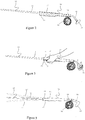
- Figure 1 shows a view of the rear part of a fishing rod 10 for fly fishing, including an oblong, thin and elastic body 11 and equipped with a gripping device 12 comprising a fore handle 13 according to the invention.
- the gripping device comprises also a butt handle 14, which does not form a part of this invention.
- the rod 10 is further equipped with a reel 16 that contains a line (not shown) rolled up on the reel 16.
- the reel 16 rotates around an axis 17 located perpendicularly on the longitude axis of the rod 10.
- the reel 16 is attached to the rod 10 by means of conventional fasteners, well known to a person skilled in the art, such as axially movable rings on the rod 10 and levers on the seat of the reel 16.
- FIG 2 shows a sketch of the lower part of a fishing rod 10, preferably a fly rod.
- the fishing rod 10 has a front and rear end, but only the rear end is shown.
- the rod 10 is composed of a blank 11, and a gripping device 12 with a corresponding fore handle 13 and a butt handle 14 attached to the rear part of the rod 10.
- Behind the fore handle 13, the rod 10 has a corresponding reel seat 18 and a reel 16 with line (not shown).
- the reel 16 rotates around an axis (not shown) positioned perpendicularly to the longitudinal direction of the rod.
- the space between the blank 11 and the inner surface 21 of the handle 13 has, according to this embodiment, been filled with a soft rubber foam material in order to avoid the possible entrance of undesirable dirt and particles between the blank 11 and the inner surface 21.
- the handle 13 is parallel with the longitudinal direction of the rod, and encloses the centre axis of the rod 10.
- the hollow handle 13 is almost circular in its rear part - the fastening section - and is thereafter gradually shaped into a marked elliptical form in its front section.
- the elliptical form gives the blank 11 increased freedom of motion during casting because there is a physical distance between the inner surface 21 of the handle 13 and the blank 11. Contact between the blank 11 and the inner surface of the handle 13 during normal use of force, is thus avoided.
- Grip enhancing areas shall be developed on the sides of the handle 13, such as furrows or perforations 22 on the surface, which gives an increased friction and a firmer grip.
- the rod 10 is equipped with a hollow handle 13, which is attached to the fishing rod 10 only at its lower part, thus enabling the lower part of the blank 11 to bend freely within the upper part of the handle 13.
- the point around which the blank 11 is allowed to oscillate is moved closer to the lower end of the rod 10, without a subsequent backwards move of the fore handle 13.
- an elliptical fore handle 13 is also better than a circular handle because it physically fills the palm of the hand in a better way, while it gives a steadier directional grip during the actual casting.
- the lower and upper front parts of the handle 13 have purposeful openings or slots 19, so that the blank 11 shall be able to bend unobstructed upwards and downwards, for example when reeling in big and strong fish, and there is a heavy load of force on the tip of the rod 10.
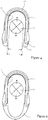
- Figure 6 shows a cross section of a closed handle 13, where the lower part of the closed handle 13 consists of a flexible material 24 that makes it possible for the blank 11 to bend practically unhindered although the handle is "closed".
- the handle is closed in order to prevent undesirable dirt and particles from entering the handle between the blank 11 and the inner surface 21 of the handle 13.
- Figure 8 shows a sectional drawing of the lower part of a double-handed fishing rod 10, equipped with a handle 13 according to the present invention, as the figure shows how the reel 16 is seated directly on the handle 13, thus enabling the blank 11 to move freely inside of the handle 13 as far as the rear part of the rod 10.
- the fishing reel 16 is seated directly on the handle 13 in such a way that the blank 11 is without physical contact with the surrounding handle 13 as far as the rear part 25 of the rod 10.
- Figure 9 shows a sectional drawing of the lower part of a double-handed fishing rod 10, specifically a spinning rod; equipped with a handle 13 according to the present invention, where the figure shows how the reel 16 is seated directly on the handle 13 so that the blank 11 may move freely inside of the handle 13 as far as the rear part 25 of the rod 10.
- the fishing reel 16 is seated directly on the handle 13 in such a way that the blank 11 is without physical contact with the surrounding handle 13 as far as the rear part 25 of the rod 10.
Description
- The present invention relates to a fishing rod, comprising an oblong, thin and elastic body; a reel for a fishing line, seated on the rod at the rear part of the rod; a gripping device comprising a handle arranged on the rear part of the rod in the area where the reel is attached to the rod, the handle comprising a stable tubular body attached to the rear end of the body only, the handle being configured to allow a relative lateral movement of the rear end of the oblong, thin elastic body inside the hollow handle.
- Casting with a fishing rod, and a fly rod in particular, is all about managing the casting technique. For the angler it is of importance to "present" a fly as far out from the rod as possible. This requires a good casting technique, using a fishing rod with optimal qualities.
- Casts with conventional double handed fly rods are made using both hands. Today's traditional double handed fly rods are equipped with a fore and a butt handle, where both are connected to the rod's centre axis and longitude.
- The prior art fore handles for fly rods are almost standardized, the actual fore handle being mainly made of cork material or foam rubber. It is common for the prior art fore handles that the handle itself is physically glued in its entire length directly to the oblong, thin and elastic body, often referred to as the "blank". A physically glued handle will contribute to a stiffening of the rear part of the rod. It gives stability, but it will also have a restrictive effect on the resilience and elasticity of the rod, because the blank is physically stiffened in the "glued" area.
- Since the fore grip constitutes an integrated and rigid part of the rod, the elastic motion of the blank will start at the fore end of the handle, farthest away from the end of the rod.
- The power needed for performing a cast with a fly rod is inflicted by hand, and the energy is transferred to the rod at the point of the grip, enclosed by the hand. The power is further transferred to the fly line or the bait/fly through the part of the blank which lies between this point and the top of the rod. The elastic nature of the blank material makes it bend like a bow and receive a potential energy which, once released, will give the fly line and the bait/fly an accelerating motion either forwards or backwards. The part of the blank which is below the point where the hand encloses the grip, will not receive a potential energy/being bent, and will thus not contribute to the acceleration of the bait/fly. The flexibility and resilience of the blank is thereby limited, since essential power reserves of a fishing rod lie in the lower part of the blank.
-
US 1,351,473 discloses a fishing rod where the grip is equipped with a handle in the shape of a tubular body. The rearmost end of the blank is fastened inside the rear end of this tubular body, in a way that to a certain extent allows the blank to move relative to the tubular body inside the tubular body. At its open end, the tubular body is provided with a cone shape design. -
US 4 051 617 discloses a fishing rod consisting of an oblong, thin and elastic body; a reel for a fishing line, seated on the rod at the rear part of the rod; a gripping devise consisting of a handle arranged at the rear part of the rod in the area where the reel is attached to the rod, the handle comprising a stable tubular body attached to the rear end of the body only, the handle allowing the rear end of the oblong, thin and elastic body to move laterally inside at least the front half of the handle. - The hollow handle disclosed both in
US 4 051 617 andUS 1 351 473 has a circular cross section along its entire length - An object of the solution according to the invention is to provide a handle that gives an ideal accuracy and a maximum utilisation of the inherent flexibility of the rod, as well as providing an ergonomically correct grip and casting motion.
- Another object of the solution according to the invention is to provide a fore handle preventing or at least reducing strains on skeleton, tendons and muscles in wrist, shoulder and arm, even for repetitive use during long periods of time.
- Another object of the invention is to provide a rod with a fore handle that improves the grip on the rod, and which is anatomically correct.
- Yet another object of the invention is to provide a fishing rod that enables good casting without requiring the use of great force and a lot of energy, and that improves the resilience and the inherent elasticity of the rod during the casting.
- Another additional object of the invention is to provide a rod that gives greater acceleration and speed during the actual cast, due to the position and the shape of the handle in relation to the blank, thus giving a longer path of motion in the forward cast.
- Yet another object of the invention is to provide a fishing rod which enables a reduction of the required force necessary to achieve an increased length of the cast, since the resilience and the elasticity of the rod are better exploited.
- Yet an additional object of the invention is to provide a fishing rod where the fore grip of the rod is in a normal distance from a possible butt handle of the rod, without reducing the rod's inherent resilience and elasticity.
- Another object of the invention is to make longer casts with less use of energy.
- According to the invention, the objects are achieved with a fishing rod as further defined in the characterizing part of claim 1, read in connection with the preamble of the claim.
- Various embodiments of the invention are defined in the dependent claims.
- According to the present invention, the handle is configured in such way that the blank is allowed to bend freely inside at least the front half of the handle without touching the inner surface of the handle. Moreover, the fore part of the handle has an elliptical form.
- According to the invention, the fore handle is provided with at least one longitudinal recess or slot on the side of the handle pointing in the same direction as the reel, so that the blank more or less freely may oscillate laterally relative to the handle. The fore handle may furthermore only be attached to the rod along maximum one half of the length of the handle, in order to prevent the physical interaction of the blank material and the enclosing handle in at least the anterior half of the handle. Moreover, it is an advantage to provide the fore handle with a corresponding opening arranged diametrically in relation to said first slot. Said second slot may have a smaller longitudinal extension than the first slot.
- The fore handle is preferably fitted parallel to the longitudinal direction of the rod, enclosing the centre axis of the rod, and may preferably be almost circular at its rear section, constituting the fastening area. The fore handle can gradually be shaped into an elliptic cylindrical form along its fore part, and can be configured on the rod in such a manner that the longitudinal slot in the fore part of the handle is orientated in the same direction as the reel, so that the blank may oscillate freely relative to the handle.
- The inner surface of the fore handle may be covered with a friction reducing and shock absorbing material in order to avoid wear of the blank and of the inner surface of the fore handle. The fore handle may also be covered with a friction enhancing and soft material, allowing a comfortable grip that stays firm under all conditions. This material may for example consist of foam rubber, cork laminate or textile.
- Furthermore, the surface of the fore handle may be formed with grip enhancing devices such as furrows or perforations, arranged on the lateral surfaces of the handle, giving increased friction and a steadier grip.
- According to the invention, a fishing rod giving improved casting lengths is obtained. Additionally, a rod giving less strain to the angler's back, shoulder and arms is provided, while casting lengths may be increased without the use of increased force.
- In addition, the solution provides an increased utilization of the inherent elasticity and resilience of the blank material. The rod according to the invention will also contribute to giving the blank increased flexibility in the plane of symmetry of the fore handle, while the lateral motions are still being limited by the handle. Such solution gives the angler increased control, and restricts undesirable lateral motions of the blank.
- According to the invention, the rod will provide an anatomically better grip than a rod with a round handle because of the elliptical fore handle, which physically fills the palm of the hand in a better way. It also gives the grip a better directional stability during the actual casting. The handle according to the invention may also be used as a handle on surf rods, spinning rods and traditional casting rods.
- According to one embodiment of the invention, the fishing reel is fixed directly to the handle in such a way that the blank is free from physical contact with the surrounding handle as far as the rearmost part of the rod.
- According to the invention, the fore handle is configured in a way that allows the oblong, thin and elastic body to move relative to the fore handle. The handle includes a formed body which is stable and tubular, fastened to the rod only at the rear end of the handle and configured in such a manner that the rear part of the rod is allowed to oscillate freely in relation to the fore part of the formed body, and inside of this body. The fore handle may be described as a tubular body where the fore, lower part is open or made by elastic material and which preferably also has an open upper part.
- One embodiment of the invention shall in the following be described more closely with references to the accompanying drawings, where:
-
Figure 1 shows a view, partly in section, of the rear part of a fishing rod for fly fishing, equipped with a gripping device according to the invention; -
Figure 2 shows a view, partly in section of the lower part of a fishing rod, also equipped with a fore handle according to the invention; -
Figure 3 shows a view of the lower part of a fishing rod equipped with a gripping device according to the present invention, and also showing the angler's grip on the butt handle and the fore handle of the gripping device; -
Figure 4 shows a cross section of a handle according to the invention, visualizing the way the handle surrounds the blank; the allowed direction of motion, as well as the position of various materials, fixed to the handle itself; -
Figure 5 shows a view of the lower part of a fishing rod, equipped with a gripping device according to the invention, where the Figure shows how the blank bends within the fore half of the fore handle; -
Figure 6 shows a cross section of a closed handle according to the invention, indicating how a closed handle surrounds the fishing rod, with the lower part of the closed handle consisting of a flexible material; -
Figure 7 shows a sketch of the lower part of a single-handed fishing rod equipped with a gripping device according to the present invention, indicating how the reel is fastened directly to the gripping device; -
Figure 8 shows a sectional view of the lower part of the fishing rod according to the invention, indicating how the reel is fixed directly to the gripping device in a way allowing the blank to move freely inside the gripping device as far as the rearmost part of the rod; and -
Figure 9 shows a sectional view of the lower part of a double handed fishing rod - specifically a spinning rod - equipped with a gripping device according to the invention, as the figure indicates how the blank may move freely inside the gripping device as far as the rearmost part of the rod. -
Figure 1 shows a view of the rear part of afishing rod 10 for fly fishing, including an oblong, thin andelastic body 11 and equipped with agripping device 12 comprising afore handle 13 according to the invention. The gripping device comprises also abutt handle 14, which does not form a part of this invention. Therod 10 is further equipped with areel 16 that contains a line (not shown) rolled up on thereel 16. Thereel 16 rotates around anaxis 17 located perpendicularly on the longitude axis of therod 10. Thereel 16 is attached to therod 10 by means of conventional fasteners, well known to a person skilled in the art, such as axially movable rings on therod 10 and levers on the seat of thereel 16. - It should be mentioned that the fishing line (not shown) may be equipped with backing, shooting line, shooting head and leader. Since none of these items form part of the invention, and since such items are well known to a person skilled in the art, these are not shown and will not be described. Moreover, it should be mentioned that the
fishing rod 10 is further equipped with line guides, through which the line runs. These are not a part of the invention either, and will thus not be described any further. -
Figure 2 shows a sketch of the lower part of afishing rod 10, preferably a fly rod. Thefishing rod 10 has a front and rear end, but only the rear end is shown. Therod 10 is composed of a blank 11, and agripping device 12 with a corresponding fore handle 13 and abutt handle 14 attached to the rear part of therod 10. Behind thefore handle 13, therod 10 has acorresponding reel seat 18 and areel 16 with line (not shown). Thereel 16 rotates around an axis (not shown) positioned perpendicularly to the longitudinal direction of the rod. Thereel 16 is attached to therod 10 by means of conventional fasteners, well known to a person skilled in the art, such as axially movable rings on therod 10 and protruding levers on thereel 16 base. The line runs through several line guides (not shown) mounted on therod 10 and comes forward through a top guide at the top of therod 10. - On double handed rods, there is an additional butt handle 14, which constitutes the rear part of the
rod 10, ref.Figure 2 . The fore handle 13, which is constructed as an elliptical, hollow tube, is made from a light and strong material such as carbon or basalt fibre, graphite and/or Kevlar®, and it may be covered with for example foam rubber, cork laminate and/or textile on the outside. Inside the front half of the fore handle, the blank 11 is configured to bend more or less freely. Thehandle 13 is not physically glued to the blank 11 along this part. Thehandle 13 is physically fastened to the blank 11 at the rear half of thehandle 13. The space between the blank 11 and theinner surface 21 of thehandle 13 has, according to this embodiment, been filled with a soft rubber foam material in order to avoid the possible entrance of undesirable dirt and particles between the blank 11 and theinner surface 21. Thehandle 13 is parallel with the longitudinal direction of the rod, and encloses the centre axis of therod 10. Thehollow handle 13 is almost circular in its rear part - the fastening section - and is thereafter gradually shaped into a marked elliptical form in its front section. The elliptical form gives the blank 11 increased freedom of motion during casting because there is a physical distance between theinner surface 21 of thehandle 13 and the blank 11. Contact between the blank 11 and the inner surface of thehandle 13 during normal use of force, is thus avoided. Thehandle 13 is mounted on the blank 11 in such a position that the major axis of the nearly elliptical cross-section lies in the primary plane of movement of the blank 11, i.e. that the distance between the blank 11 and thehandle 13 is longer in the vertical direction, thus avoiding the creation of a break point during casting. -
Figure 3 shows thegripping device 12 according to the invention, seen from one side. Externally, the fore handle 13 is covered with different materials to give the handle optimum qualities. The materials may be cork laminate, soft rubber foam and textile. These have unique qualities and are considered used to achieve a firmer and more comfortable grip under all conditions (cold, warm, wet, dry). Externally, the handle may be equipped withgrip enhancing devices 22, such asfurrows 22 or perforations. Such devices on the surface give an increased friction and a firmer grip. The use offurrows 22 or perforations is intended at the lower front part of thehandle 13, which is the normal casting grip area. The fore part of thehandle 13 is intended to be equipped with a comfortable externaltactile covering 23, such as cork laminate, foam rubber and/or textile. -
Figure 4 shows a section through therod 10 where the blank 11 is centred inside thehandle 13. The external diameter of the blank 11 is smaller than the internal width of thehandle 13. The lower and upper front parts of thehandle 13 are open, so that the blank 11 is allowed to bend unobstructed upwards and downwards, during casting and for example when reeling in big and strong fish, where the strain on the blank 11 may be great, and also to enable theinner surface 21 of the handle to be covered with friction reducing and shock absorbing material to avoid wear of the surface of the blank 11 and the inner surface of thehandle 13. On the outside, thehandle 13 is covered with friction enhancing and soft material 23 - giving a both comfortable and firm grip under all kinds of conditions. Additionally, the use of rubber foam, cork laminate or textile is possible, making it pleasant to hold thehandle 13 under all kinds of conditions (cold, warm, wet, dry). Grip enhancing areas shall be developed on the sides of thehandle 13, such as furrows orperforations 22 on the surface, which gives an increased friction and a firmer grip. -
Figure 5 shows how the blank 11 is allowed to bend freely inside at least the front half of thehandle 13. The elliptical form of thehandle 13 makes it possible for the blank 11 to bend unobstructed during forward casting 11' as well as during backward casting 11 ", without touching the inner surface of thehandle 13. The load of energy on therod 10 is definitely greatest when the blank 11 is bent downward 11' for example when reeling in big and strong fish. The load is also great during overhead casting. This makes therod 10 bend during the backward cast as well as during the forward cast. The sideways bend will be much smaller because of the direction of the forces in play. - As described above, the
rod 10 is equipped with ahollow handle 13, which is attached to thefishing rod 10 only at its lower part, thus enabling the lower part of the blank 11 to bend freely within the upper part of thehandle 13. This gives an increased utilization of the elasticity and resilience of the blank 11. According to the invention, the point around which the blank 11 is allowed to oscillate is moved closer to the lower end of therod 10, without a subsequent backwards move of thefore handle 13. - Moreover, the
hollow handle 13 is approximately circular or slightly elliptical in its rear part where the blank 10 is fastened, and thereafter gradually shapes into a marked elliptical form in its front part. The elliptical form gives the blank 11 a free path of motion during casting, because there is a physical distance between thehandle 13 and the blank 11. Contact between the blank 11 and the inner surface of thehandle 13 during normal use of force, is thus avoided. Thehandle 13 is mounted on the blank 11 in such a position that the major axis of the nearly elliptical cross-section lies in the primary plane of movement of the blank, i.e. that the distance between the blank 11 and thehandle 13 is greater in the vertical direction, while the sideways distance between the blank 11 and thehandle 13 is smaller. An increased flexibility in the vertical plane of the blank 11 is thus obtained, whereas thehandle 13 will still limit the lateral movements of the blank 11. This gives the angler increased control, and reduces undesirable lateral movements of the blank 11. A possible appearance of a break point during casting is thus avoided, because the blank 11 oscillates more in the vertical plane, and considerably less sideways. - In anatomical terms, an elliptical fore handle 13 is also better than a circular handle because it physically fills the palm of the hand in a better way, while it gives a steadier directional grip during the actual casting. The lower and upper front parts of the
handle 13 have purposeful openings orslots 19, so that the blank 11 shall be able to bend unobstructed upwards and downwards, for example when reeling in big and strong fish, and there is a heavy load of force on the tip of therod 10. -
Figure 6 shows a cross section of aclosed handle 13, where the lower part of theclosed handle 13 consists of aflexible material 24 that makes it possible for the blank 11 to bend practically unhindered although the handle is "closed". The handle is closed in order to prevent undesirable dirt and particles from entering the handle between the blank 11 and theinner surface 21 of thehandle 13. -
Figure 7 shows thehandle 13, seen from one side of a single-handedfishing rod 10. Thehandle 13 may be used on single-handed and double-handed casting rods. The principles are the same for both of said rods 10: Thehandle 13 allows the blank 11 freedom of movement during casting, because there is a physical distance between thehandle 13 and the blank 11. The blank 11 is allowed to bend freely inside at least the front half of the handle. Thehandle 13 is not physically glued to the blank 11 in this section. Thehandle 13 is physically fastened to the blank 11 at no more than the rear half of thehandle 13. -
Figure 8 shows a sectional drawing of the lower part of a double-handed fishing rod 10, equipped with ahandle 13 according to the present invention, as the figure shows how thereel 16 is seated directly on thehandle 13, thus enabling the blank 11 to move freely inside of thehandle 13 as far as the rear part of therod 10. According to one embodiment of the invention, thefishing reel 16 is seated directly on thehandle 13 in such a way that the blank 11 is without physical contact with the surroundinghandle 13 as far as therear part 25 of therod 10. -
Figure 9 shows a sectional drawing of the lower part of a double-handed fishing rod 10, specifically a spinning rod; equipped with ahandle 13 according to the present invention, where the figure shows how thereel 16 is seated directly on thehandle 13 so that the blank 11 may move freely inside of thehandle 13 as far as therear part 25 of therod 10. According to one embodiment of the invention, thefishing reel 16 is seated directly on thehandle 13 in such a way that the blank 11 is without physical contact with the surroundinghandle 13 as far as therear part 25 of therod 10.
Claims (7)
- Fishing rod (10), comprising a blank which is an oblong, thin and elastic body (11); a reel (16) for a fishing line, seated on the rod (10) at a rear part of the rod (10); a gripping device (12) comprising a handle (13) arranged on the rear part of the rod (10) in an area where the reel (16) is attached to the rod (10), the handle (13) comprising a stable tubular body attached to a rear end of the blank (11) only, the handle (13) being closed at one end and open at the opposite end, and being configured to allow a relative lateral movement of the rear end of the oblong, thin elastic body (11) inside the hollow handle (13),
characterized in that a fore part of the handle (13) has an elliptical cross section, where a distance between the blank (11) and the open end of the handle (13) is greater in a vertical direction than a sidewise distance, a major axis of the elliptical cross section lying in a primary plane of movement of the blank (11), or that the handle (13) is provided with a longitudinal slot on a side of the handle (13) where the real is seated, allowing the blank (11) to bend freely inside at least a front half of the handle (13) without touching an inner surface of the handle (13). - Fishing rod according to claim 1 in so far as a fore part of the handle (13) has an elliptical cross section, wherein the hollow handle (13) has a circular cross sectional shape at its rear part where the oblong, thin, elastic body (11) is fixed to the handle (13) and changes gradually into the elliptical shape at its front section.
- Fishing rod according to claim 1 or 2, wherein the handle (13) forms. a closed body, configured to allow the oblong, thin, elastic body (11) to more or less freely oscillate upwards and downwards inside the handle (13).
- Fishing rod according to claim 1 in so far as the handle (13) is provided with a longitudinal slot, wherein the handle (13) is provided with an opening or slot on an opposite side of the handle (13).
- Fishing rod (10) according to one of the claims 1 to 4, where the handle (13) is only fixed to the fishing rod along maximum halt of the handle (13), so that accordingly, the blank (11) is not in physical contact with the surrounding handle (13) in at least the fore half of the handle (13).
- Fishing rod (10) according to one of the claims 1 to 5, where the fore end of the handle (13) is equipped with an enforcement in the form or a ring, with a considerably larger opening than the remaining part of the handle.
- Fishing rod (10) according to one of the claims 1 to 6, wherein the inner surface (21) is covered with friction reducing and shock absorbing material, in order to avoid wear of the surface of the blank (11) and the inner surface (21) of the handle (13).
Applications Claiming Priority (3)
| Application Number | Priority Date | Filing Date | Title |
|---|---|---|---|
| NO20073599A NO326924B1 (en) | 2007-07-12 | 2007-07-12 | Handle for fly rod |
| NO20076177A NO20076177A (en) | 2007-11-30 | 2007-11-30 | Fishing rod. |
| EP08159603.3A EP2014158B9 (en) | 2007-07-12 | 2008-07-03 | Handle for fishing rod |
Related Parent Applications (2)
| Application Number | Title | Priority Date | Filing Date |
|---|---|---|---|
| EP08159603.3A Division EP2014158B9 (en) | 2007-07-12 | 2008-07-03 | Handle for fishing rod |
| EP08159603.3 Division | 2008-07-03 |
Publications (2)
| Publication Number | Publication Date |
|---|---|
| EP2532229A1 EP2532229A1 (en) | 2012-12-12 |
| EP2532229B1 true EP2532229B1 (en) | 2017-08-30 |
Family
ID=39916346
Family Applications (2)
| Application Number | Title | Priority Date | Filing Date |
|---|---|---|---|
| EP08159603.3A Not-in-force EP2014158B9 (en) | 2007-07-12 | 2008-07-03 | Handle for fishing rod |
| EP12182883.4A Active EP2532229B1 (en) | 2007-07-12 | 2008-07-03 | Fore handle for fishing rod |
Family Applications Before (1)
| Application Number | Title | Priority Date | Filing Date |
|---|---|---|---|
| EP08159603.3A Not-in-force EP2014158B9 (en) | 2007-07-12 | 2008-07-03 | Handle for fishing rod |
Country Status (6)
| Country | Link |
|---|---|
| US (1) | US7980018B2 (en) |
| EP (2) | EP2014158B9 (en) |
| CA (1) | CA2637091C (en) |
| DK (2) | DK2014158T3 (en) |
| NZ (1) | NZ569656A (en) |
| RU (1) | RU2468578C2 (en) |
Families Citing this family (8)
| Publication number | Priority date | Publication date | Assignee | Title |
|---|---|---|---|---|
| WO2007109058A2 (en) * | 2006-03-15 | 2007-09-27 | Millen Brian W | Device and method for casting |
| DK2014158T3 (en) * | 2007-07-12 | 2013-03-11 | Robert Selfors | Handle for fishing rod |
| US20090113782A1 (en) * | 2007-11-05 | 2009-05-07 | Joseph Earl Driggers | Universal fishing rod safety grip |
| EP3531660B1 (en) * | 2014-02-04 | 2020-08-05 | Sony Corporation | Media strem from sender seen on receiver side before confirming receipt of media stream |
| US20160044903A1 (en) * | 2014-08-14 | 2016-02-18 | Nathaniel Paul GRAHL | Fishing rod handle with free-floating rod blank |
| RU196022U1 (en) * | 2019-12-09 | 2020-02-13 | Владимир Васильевич Галайко | AX |
| USD964504S1 (en) | 2020-09-16 | 2022-09-20 | Bob Landreville | Grip handle for a spin casting fishing rod |
| USD964505S1 (en) | 2020-09-16 | 2022-09-20 | Bob Landreville | Grip handle for a bait casting fishing rod |
Family Cites Families (118)
| Publication number | Priority date | Publication date | Assignee | Title |
|---|---|---|---|---|
| US206264A (en) * | 1878-07-23 | Improvement in fishing-rods | ||
| US583016A (en) * | 1897-05-25 | Willis ii | ||
| US270460A (en) * | 1883-01-09 | William mitchell | ||
| US828557A (en) * | 1906-03-21 | 1906-08-14 | Edward F Payne | Fishing-rod. |
| US841761A (en) * | 1906-08-02 | 1907-01-22 | Leander L Bartlett | Fishing-rod. |
| US887753A (en) * | 1908-02-17 | 1908-05-19 | Matthias A Beck | Casting-rod. |
| US911119A (en) * | 1908-05-28 | 1909-02-02 | William J Farr | Fishing-rod. |
| US980942A (en) * | 1910-04-11 | 1911-01-10 | Charles H Hanson | Fishing-rod. |
| US1013333A (en) * | 1911-08-24 | 1912-01-02 | Horton Mfg Co Inc | Fishing-rod. |
| US1351473A (en) | 1919-07-01 | 1920-08-31 | Hardy Forster | Fishing-rod |
| US1513567A (en) * | 1923-03-12 | 1924-10-28 | Eraphia A Swihart | Automatic fishing pole |
| US1625510A (en) * | 1924-10-14 | 1927-04-19 | Winchester Repeating Arms Co | Telescopic fishing rod |
| US1593957A (en) * | 1925-10-14 | 1926-07-27 | Roy F B Shaver | Fish rod |
| US1731173A (en) * | 1927-12-20 | 1929-10-08 | Pope William Eddie | Fishing rod |
| US1898323A (en) * | 1930-10-31 | 1933-02-21 | Ralph R Teetor | Handle for fishing rods |
| US1972518A (en) * | 1932-05-24 | 1934-09-04 | Grandjean Charles | Walking stick fishing rod |
| US1931303A (en) * | 1932-07-14 | 1933-10-17 | Sturgis William Bayard | Fly rod handle |
| US2000263A (en) * | 1933-11-11 | 1935-05-07 | Ralph R Teetor | Fishing rod handle |
| US1985427A (en) * | 1934-01-06 | 1934-12-25 | William H Richardson | Flexible ferrule |
| US2018923A (en) * | 1934-09-29 | 1935-10-29 | Joseph L Potter | Resilient attachment for handles |
| US2065153A (en) * | 1935-12-16 | 1936-12-22 | William S Proudfit | Casting rod attachment |
| US2149837A (en) * | 1937-08-23 | 1939-03-07 | I F Mcdonnell | Fishing rod handle |
| US2283816A (en) * | 1941-10-10 | 1942-05-19 | Louis P Loutrel | Grip handle for fishing rods |
| US2306638A (en) * | 1941-11-06 | 1942-12-29 | John C Meisler | Fishing rod |
| US2483071A (en) * | 1947-12-03 | 1949-09-27 | Lester G Stine | Fishing rod |
| US2600259A (en) * | 1948-01-21 | 1952-06-10 | Palmer Philip Charles | Fishing rod |
| US2577575A (en) * | 1948-07-13 | 1951-12-04 | Gephart Mfg Company | Fishing rod |
| US2559934A (en) * | 1948-07-22 | 1951-07-10 | Damond E Briney | Fishing rod with integral resilient means |
| US2685755A (en) * | 1952-07-28 | 1954-08-10 | Wilfred J Gorenflo | Fishing rod handle |
| US2711047A (en) * | 1953-05-18 | 1955-06-21 | Claud M Shepherd | Thumb rest for fishing rod |
| US2737747A (en) * | 1953-11-18 | 1956-03-13 | Chisholm Ryder Co Inc | Handle for fishing poles |
| US3006098A (en) * | 1958-12-08 | 1961-10-31 | Raymond J Harke | Fishing rod handle with releasable reel and rod clamping mechanism |
| US3073055A (en) * | 1959-04-24 | 1963-01-15 | Charles N Edwards | Handle for selectively usable fishing rods |
| US3216144A (en) * | 1964-02-25 | 1965-11-09 | Vojinov John | All-purpose fishing rod |
| US3296732A (en) | 1964-05-14 | 1967-01-10 | Finn H Magnus | Casting rig |
| US3372510A (en) * | 1965-08-13 | 1968-03-12 | Albert J. Arsenault | Fishing rod handling device |
| CH432927A (en) * | 1966-02-01 | 1967-03-31 | Sieber Hans Ulrich | fishing rod |
| US3436858A (en) * | 1966-07-14 | 1969-04-08 | Clifford A Shaffer | Automatic bait release caster |
| US3507069A (en) * | 1968-08-02 | 1970-04-21 | William A Borba Sr | Casting rod |
| US3888035A (en) * | 1974-03-18 | 1975-06-10 | Ralph P Totten | Ice fishing rod |
| US4014129A (en) * | 1975-03-26 | 1977-03-29 | Theodore Capra | Fishing rod stabilizing handle |
| US4051617A (en) * | 1976-09-16 | 1977-10-04 | Bjorn Lie | Automatic line release for spin fishing equipment |
| US4214395A (en) * | 1978-10-17 | 1980-07-29 | Caldwell Benjamin P Jr | Lever assemblies |
| US4559735A (en) * | 1985-01-08 | 1985-12-24 | Batick Jr Philip | Fishing rod and reel holder for handicapped persons |
| US4653215A (en) * | 1985-06-10 | 1987-03-31 | Strader James W | Fishing rod |
| US4644680A (en) * | 1986-03-10 | 1987-02-24 | Brunswick Corporation | Transmitter rod |
| US4654996A (en) * | 1986-05-16 | 1987-04-07 | Gieselman David A | Casting rod handle with pistol grip and butt extension |
| US4651461A (en) * | 1986-06-16 | 1987-03-24 | Williams Charles R | Fishing rod handle |
| US4796373A (en) * | 1987-05-11 | 1989-01-10 | Struntz Bernard J | Fishing rod with improved handgrip |
| US4822087A (en) * | 1987-12-14 | 1989-04-18 | Decarlo Tony J | Lift improvement device |
| NZ222953A (en) * | 1987-12-16 | 1990-06-26 | Roger Martyn Gough | Fishing rod with a hook for winding and unwinding a line on a reel |
| US4858365A (en) * | 1989-03-13 | 1989-08-22 | Struntz Bernard J | Fishing rod handgrips |
| WO1991009518A1 (en) * | 1990-01-04 | 1991-07-11 | Ashman Austin H | Fishing rod and/or attachement for a fishing rod |
| US5237770A (en) * | 1990-07-13 | 1993-08-24 | Wilson Creek | Fly fishing rod and reel combination |
| US5259140A (en) * | 1991-01-29 | 1993-11-09 | Epperson Frank E | Telescoping fishing rod assembly |
| US5159775A (en) * | 1991-04-26 | 1992-11-03 | Sutula Jr Daniel P | Support handle for a fishing rod |
| US5197218A (en) * | 1992-02-04 | 1993-03-30 | Legard Robert L | Ice fishing pole |
| US5313735A (en) * | 1992-03-02 | 1994-05-24 | Latouche Desmond J | Rotatable handle extension for fishing rods and the like |
| US5363586A (en) * | 1993-08-30 | 1994-11-15 | Balkenbush James W | Dual-grip fishing rod handle |
| US5390438A (en) * | 1994-02-22 | 1995-02-21 | Warren, Jr.; Alan M. | Arm support for fishing rod |
| US6092324A (en) * | 1995-05-26 | 2000-07-25 | The Orvis Company, Inc. | Damped fishing rod |
| US5774937A (en) * | 1996-02-06 | 1998-07-07 | Caminos; Frank | Handle adapter |
| US6237274B1 (en) * | 1996-02-13 | 2001-05-29 | Burton W. Head | Fishing rod handle attachment |
| JPH10146142A (en) * | 1996-09-20 | 1998-06-02 | Masafumi Maeda | Fishing rod with fish signal-sensing handle |
| JPH10276627A (en) * | 1997-04-11 | 1998-10-20 | Shimano Inc | Fishing rod |
| US5915943A (en) * | 1997-04-24 | 1999-06-29 | Berkley Inc. | Fishing rod with bulge |
| US5992079A (en) * | 1998-02-11 | 1999-11-30 | Michels; Neil D. | Wristsaver fishing rod handle and system |
| US6145237A (en) * | 1998-03-26 | 2000-11-14 | Charles C. Worth Corporation | Unitary fishing rod with integral features |
| US6065240A (en) * | 1998-06-29 | 2000-05-23 | Paddock; William L. | Arm rest for pole-like objects |
| JP3985921B2 (en) * | 1998-08-17 | 2007-10-03 | 株式会社シマノ | Grip and fishing rod equipped with the same |
| US6067741A (en) * | 1998-08-21 | 2000-05-30 | Eaton; William O. | Fishing rod and handle extension |
| RU2149545C1 (en) * | 1998-09-25 | 2000-05-27 | Розанов Иван Николаевич | Fishing rod |
| JP2000270724A (en) * | 1999-03-19 | 2000-10-03 | Daiwa Seiko Inc | Fishing rod |
| JP2001061380A (en) * | 1999-08-26 | 2001-03-13 | Shimano Inc | Fitting structure for fishing rod |
| US6295755B1 (en) * | 1999-10-25 | 2001-10-02 | Michael Macaluso | Adjustable arm support for fishing rod handle |
| US6493982B1 (en) * | 1999-10-25 | 2002-12-17 | Michael Macaluso | Arm cradle for fishing rod |
| US6763628B1 (en) * | 1999-11-17 | 2004-07-20 | Norman Bartlett | Fly casting trainer and method of teaching fly casting |
| US6347477B1 (en) * | 2000-02-04 | 2002-02-19 | Brad Hopper | Fishing rod with stress relief grip and forearm support |
| CA2315442C (en) * | 2000-08-10 | 2008-05-27 | Wye-Yoshi Corporation | Fishing rod handle |
| JP2002051672A (en) * | 2000-08-11 | 2002-02-19 | Mamiya Op Co Ltd | Rod for jigging |
| GB0025580D0 (en) * | 2000-10-18 | 2000-12-06 | Hays Roderick S | Improvements in and relating to fishing rods |
| JP4541570B2 (en) * | 2001-01-16 | 2010-09-08 | メガバス株式会社 | Fishing rod grip |
| US20020189149A1 (en) * | 2001-06-18 | 2002-12-19 | Louis Borgeat | Fly fishing rod having a detachable reel seat and waist holder therefor |
| US7086195B2 (en) * | 2001-06-18 | 2006-08-08 | Louis Borgeat | Fly fishing rod having a detachable reel seat and waist holder therefore |
| DE10202773B4 (en) * | 2002-01-25 | 2005-11-10 | Klöber, Martin | Fishing rod with bendable handpiece |
| US6748691B2 (en) * | 2002-03-06 | 2004-06-15 | David A. Doucette | Wrist brace for anglers |
| JP4007583B2 (en) * | 2002-05-01 | 2007-11-14 | 株式会社シマノ | Connecting structure of frame |
| JP2004081064A (en) * | 2002-08-26 | 2004-03-18 | Tamaki Ishizaki | Grip for fishing use |
| US6931781B2 (en) * | 2003-06-25 | 2005-08-23 | Eagle Mountain Brokers, Inc. | Fishing rod |
| JP2005073565A (en) * | 2003-08-29 | 2005-03-24 | Daiwa Seiko Inc | Elbow pad grip for fishing rod |
| US6922936B2 (en) * | 2003-09-04 | 2005-08-02 | Eagle Mountain Brokers, Inc. | Fishing rod connector, and connector assemblies for fishing poles |
| US20050072037A1 (en) * | 2003-10-02 | 2005-04-07 | Markley Duane C. | Fishing poles, counter-balancing apparatus for fishing poles and handles, and methods for balancing fishing poles |
| US7226365B2 (en) * | 2003-12-11 | 2007-06-05 | Gregory Qualizza | Shaft structure with adjustable and self-regulated stiffness |
| JP2005304420A (en) * | 2004-04-23 | 2005-11-04 | Zuiile:Kk | Rod for fishing |
| US8307579B2 (en) * | 2004-05-19 | 2012-11-13 | Thomas John Nyland | Arm support for use with a fishing rod |
| US7533484B2 (en) * | 2004-06-21 | 2009-05-19 | Eagle Mountain Brokers, Inc. | Fishing pole, anti-wrap line guide for a fishing pole, and fishing rod |
| US20060086033A1 (en) * | 2004-10-27 | 2006-04-27 | Barrett Alan J | Fishing rod handle |
| US20060096153A1 (en) * | 2004-11-11 | 2006-05-11 | Jung Man Y | Flexible segment fishing pole |
| US20070033855A1 (en) * | 2004-11-11 | 2007-02-15 | Jung Man Y | Flexible segment fishing pole |
| JP2006158362A (en) * | 2004-12-03 | 2006-06-22 | Tsuneo Kanbe | Fishing rod equipped with holding assembly in which grip and elbow piece are integrally constituted |
| JP4526122B2 (en) * | 2005-01-06 | 2010-08-18 | 株式会社シマノ | Fishing rod grip structure |
| JP4308154B2 (en) * | 2005-01-14 | 2009-08-05 | 株式会社がまかつ | fishing rod |
| US7454862B2 (en) * | 2005-02-15 | 2008-11-25 | Eagle Mountain Brokers, Inc. | Fishing pole handle hinge assembly and fishing pole handle |
| US20060230669A1 (en) * | 2005-03-07 | 2006-10-19 | Markley Duane C | Fishing pole handle attachments and fishing pole handle |
| KR100642066B1 (en) * | 2005-08-01 | 2006-11-10 | 배선암 | Fishing rod for using in fishing place with a lot of water plant |
| NO324033B1 (en) * | 2005-12-01 | 2007-07-30 | Zpey System As | Fishing rod |
| JP2007244352A (en) * | 2006-03-14 | 2007-09-27 | Tsuneo Kanbe | Holding tool for fishing rod, equipped with movable elbow supporter |
| WO2007109058A2 (en) * | 2006-03-15 | 2007-09-27 | Millen Brian W | Device and method for casting |
| JP4812009B2 (en) * | 2006-04-19 | 2011-11-09 | 株式会社シマノ | Reel seat for spinning reel installation |
| JP2008017793A (en) * | 2006-07-14 | 2008-01-31 | Shimano Inc | Telescopic extension rod |
| JP4748598B2 (en) * | 2006-08-22 | 2011-08-17 | 株式会社シマノ | Fishing rod elbow holder and fishing rod |
| JP2008131885A (en) * | 2006-11-28 | 2008-06-12 | Shimano Inc | Stretchable fishing rod |
| US20080244956A1 (en) * | 2007-04-03 | 2008-10-09 | Shimano American Corporation | Fishing rod including a hook receptacle |
| DK2014158T3 (en) * | 2007-07-12 | 2013-03-11 | Robert Selfors | Handle for fishing rod |
| JP2009131200A (en) * | 2007-11-30 | 2009-06-18 | Daiwa Seiko Inc | Fishing rod |
| US20090293339A1 (en) * | 2008-05-28 | 2009-12-03 | John Bartholomew | Athletic device tensioner |
| US7854086B2 (en) * | 2008-08-28 | 2010-12-21 | Chi Huynh | Fishing rod with ergonomic handle |
| US8413366B2 (en) * | 2009-04-01 | 2013-04-09 | Winthrop Tool Llc | Adjustable butt and reel seat for a fishing rod |
-
2008
- 2008-07-03 DK DK08159603.3T patent/DK2014158T3/en active
- 2008-07-03 DK DK12182883.4T patent/DK2532229T3/en active
- 2008-07-03 EP EP08159603.3A patent/EP2014158B9/en not_active Not-in-force
- 2008-07-03 EP EP12182883.4A patent/EP2532229B1/en active Active
- 2008-07-08 NZ NZ569656A patent/NZ569656A/en not_active IP Right Cessation
- 2008-07-09 CA CA2637091A patent/CA2637091C/en active Active
- 2008-07-11 RU RU2008128120/13A patent/RU2468578C2/en active
- 2008-07-11 US US12/171,921 patent/US7980018B2/en active Active
Non-Patent Citations (1)
| Title |
|---|
| None * |
Also Published As
| Publication number | Publication date |
|---|---|
| EP2014158B1 (en) | 2012-12-05 |
| US20090013584A1 (en) | 2009-01-15 |
| NZ569656A (en) | 2008-11-28 |
| US7980018B2 (en) | 2011-07-19 |
| EP2014158A3 (en) | 2010-06-02 |
| DK2532229T3 (en) | 2017-12-04 |
| CA2637091C (en) | 2015-05-05 |
| CA2637091A1 (en) | 2009-01-12 |
| RU2008128120A (en) | 2010-01-20 |
| EP2014158A2 (en) | 2009-01-14 |
| EP2014158B9 (en) | 2013-08-14 |
| DK2014158T3 (en) | 2013-03-11 |
| EP2532229A1 (en) | 2012-12-12 |
| RU2468578C2 (en) | 2012-12-10 |
Similar Documents
| Publication | Publication Date | Title |
|---|---|---|
| EP2532229B1 (en) | Fore handle for fishing rod | |
| CA2315442C (en) | Fishing rod handle | |
| KR102653297B1 (en) | A moveable hood for a reel seat, a reel seat using the moveable hood, and a fishing rod using the reel seat | |
| US20060101702A1 (en) | Bait-casting rod handle | |
| US4905400A (en) | Contoured spinning rod and handle assembly | |
| EP1956892B1 (en) | Fishing rod | |
| KR101935724B1 (en) | Lure rod | |
| US4817324A (en) | Palming grip fishing rod and reel assembly | |
| US20190216069A1 (en) | Ergonomic spincast reel | |
| US6067741A (en) | Fishing rod and handle extension | |
| TWI810826B (en) | Reel seat and fishing rod provided with the same | |
| JP4225927B2 (en) | fishing rod | |
| JP2005130767A (en) | Fishing rod | |
| JP2020103324A (en) | Cylindrical reel seat and reel seat body as well as fishing rod | |
| NO326907B1 (en) | Fishing rod. | |
| JP2001327232A (en) | Spinning reel | |
| MX2008006982A (en) | Fishing rod | |
| CA2354218A1 (en) | Fishing rod handle | |
| JPH0947192A (en) | Device for attaching reel to fishing rod | |
| CN101321458A (en) | Fishing rod | |
| JP2012135289A (en) | Fishing rod | |
| JP2006006279A (en) | Fishing rod |
Legal Events
| Date | Code | Title | Description |
|---|---|---|---|
| PUAI | Public reference made under article 153(3) epc to a published international application that has entered the european phase |
Free format text: ORIGINAL CODE: 0009012 |
|
| AC | Divisional application: reference to earlier application |
Ref document number: 2014158 Country of ref document: EP Kind code of ref document: P |
|
| AK | Designated contracting states |
Kind code of ref document: A1 Designated state(s): AT BE BG CH CY CZ DE DK EE ES FI FR GB GR HR HU IE IS IT LI LT LU LV MC MT NL NO PL PT RO SE SI SK TR |
|
| 17P | Request for examination filed |
Effective date: 20130612 |
|
| RBV | Designated contracting states (corrected) |
Designated state(s): AT BE BG CH CY CZ DE DK EE ES FI FR GB GR HR HU IE IS IT LI LT LU LV MC MT NL NO PL PT RO SE SI SK TR |
|
| 17Q | First examination report despatched |
Effective date: 20160222 |
|
| GRAP | Despatch of communication of intention to grant a patent |
Free format text: ORIGINAL CODE: EPIDOSNIGR1 |
|
| INTG | Intention to grant announced |
Effective date: 20161021 |
|
| GRAJ | Information related to disapproval of communication of intention to grant by the applicant or resumption of examination proceedings by the epo deleted |
Free format text: ORIGINAL CODE: EPIDOSDIGR1 |
|
| STAA | Information on the status of an ep patent application or granted ep patent |
Free format text: STATUS: EXAMINATION IS IN PROGRESS |
|
| GRAP | Despatch of communication of intention to grant a patent |
Free format text: ORIGINAL CODE: EPIDOSNIGR1 |
|
| STAA | Information on the status of an ep patent application or granted ep patent |
Free format text: STATUS: GRANT OF PATENT IS INTENDED |
|
| INTC | Intention to grant announced (deleted) | ||
| INTG | Intention to grant announced |
Effective date: 20170216 |
|
| GRAS | Grant fee paid |
Free format text: ORIGINAL CODE: EPIDOSNIGR3 |
|
| GRAA | (expected) grant |
Free format text: ORIGINAL CODE: 0009210 |
|
| STAA | Information on the status of an ep patent application or granted ep patent |
Free format text: STATUS: THE PATENT HAS BEEN GRANTED |
|
| GRAT | Correction requested after decision to grant or after decision to maintain patent in amended form |
Free format text: ORIGINAL CODE: EPIDOSNCDEC |
|
| AC | Divisional application: reference to earlier application |
Ref document number: 2014158 Country of ref document: EP Kind code of ref document: P |
|
| AK | Designated contracting states |
Kind code of ref document: B1 Designated state(s): AT BE BG CH CY CZ DE DK EE ES FI FR GB GR HR HU IE IS IT LI LT LU LV MC MT NL NO PL PT RO SE SI SK TR |
|
| REG | Reference to a national code |
Ref country code: GB Ref legal event code: FG4D |
|
| REG | Reference to a national code |
Ref country code: CH Ref legal event code: EP |
|
| REG | Reference to a national code |
Ref country code: AT Ref legal event code: REF Ref document number: 922621 Country of ref document: AT Kind code of ref document: T Effective date: 20170915 |
|
| REG | Reference to a national code |
Ref country code: IE Ref legal event code: FG4D |
|
| REG | Reference to a national code |
Ref country code: DE Ref legal event code: R096 Ref document number: 602008051959 Country of ref document: DE |
|
| REG | Reference to a national code |
Ref country code: SE Ref legal event code: TRGR |
|
| REG | Reference to a national code |
Ref country code: DK Ref legal event code: T3 Effective date: 20171127 |
|
| REG | Reference to a national code |
Ref country code: NL Ref legal event code: MP Effective date: 20170830 |
|
| REG | Reference to a national code |
Ref country code: LT Ref legal event code: MG4D |
|
| REG | Reference to a national code |
Ref country code: AT Ref legal event code: MK05 Ref document number: 922621 Country of ref document: AT Kind code of ref document: T Effective date: 20170830 |
|
| PG25 | Lapsed in a contracting state [announced via postgrant information from national office to epo] |
Ref country code: AT Free format text: LAPSE BECAUSE OF FAILURE TO SUBMIT A TRANSLATION OF THE DESCRIPTION OR TO PAY THE FEE WITHIN THE PRESCRIBED TIME-LIMIT Effective date: 20170830 Ref country code: HR Free format text: LAPSE BECAUSE OF FAILURE TO SUBMIT A TRANSLATION OF THE DESCRIPTION OR TO PAY THE FEE WITHIN THE PRESCRIBED TIME-LIMIT Effective date: 20170830 Ref country code: NO Free format text: LAPSE BECAUSE OF FAILURE TO SUBMIT A TRANSLATION OF THE DESCRIPTION OR TO PAY THE FEE WITHIN THE PRESCRIBED TIME-LIMIT Effective date: 20171130 Ref country code: LT Free format text: LAPSE BECAUSE OF FAILURE TO SUBMIT A TRANSLATION OF THE DESCRIPTION OR TO PAY THE FEE WITHIN THE PRESCRIBED TIME-LIMIT Effective date: 20170830 Ref country code: FI Free format text: LAPSE BECAUSE OF FAILURE TO SUBMIT A TRANSLATION OF THE DESCRIPTION OR TO PAY THE FEE WITHIN THE PRESCRIBED TIME-LIMIT Effective date: 20170830 |
|
| PG25 | Lapsed in a contracting state [announced via postgrant information from national office to epo] |
Ref country code: IS Free format text: LAPSE BECAUSE OF FAILURE TO SUBMIT A TRANSLATION OF THE DESCRIPTION OR TO PAY THE FEE WITHIN THE PRESCRIBED TIME-LIMIT Effective date: 20171230 Ref country code: BG Free format text: LAPSE BECAUSE OF FAILURE TO SUBMIT A TRANSLATION OF THE DESCRIPTION OR TO PAY THE FEE WITHIN THE PRESCRIBED TIME-LIMIT Effective date: 20171130 Ref country code: GR Free format text: LAPSE BECAUSE OF FAILURE TO SUBMIT A TRANSLATION OF THE DESCRIPTION OR TO PAY THE FEE WITHIN THE PRESCRIBED TIME-LIMIT Effective date: 20171201 Ref country code: LV Free format text: LAPSE BECAUSE OF FAILURE TO SUBMIT A TRANSLATION OF THE DESCRIPTION OR TO PAY THE FEE WITHIN THE PRESCRIBED TIME-LIMIT Effective date: 20170830 Ref country code: ES Free format text: LAPSE BECAUSE OF FAILURE TO SUBMIT A TRANSLATION OF THE DESCRIPTION OR TO PAY THE FEE WITHIN THE PRESCRIBED TIME-LIMIT Effective date: 20170830 |
|
| PG25 | Lapsed in a contracting state [announced via postgrant information from national office to epo] |
Ref country code: NL Free format text: LAPSE BECAUSE OF FAILURE TO SUBMIT A TRANSLATION OF THE DESCRIPTION OR TO PAY THE FEE WITHIN THE PRESCRIBED TIME-LIMIT Effective date: 20170830 |
|
| PG25 | Lapsed in a contracting state [announced via postgrant information from national office to epo] |
Ref country code: PL Free format text: LAPSE BECAUSE OF FAILURE TO SUBMIT A TRANSLATION OF THE DESCRIPTION OR TO PAY THE FEE WITHIN THE PRESCRIBED TIME-LIMIT Effective date: 20170830 Ref country code: CZ Free format text: LAPSE BECAUSE OF FAILURE TO SUBMIT A TRANSLATION OF THE DESCRIPTION OR TO PAY THE FEE WITHIN THE PRESCRIBED TIME-LIMIT Effective date: 20170830 Ref country code: RO Free format text: LAPSE BECAUSE OF FAILURE TO SUBMIT A TRANSLATION OF THE DESCRIPTION OR TO PAY THE FEE WITHIN THE PRESCRIBED TIME-LIMIT Effective date: 20170830 |
|
| PG25 | Lapsed in a contracting state [announced via postgrant information from national office to epo] |
Ref country code: IT Free format text: LAPSE BECAUSE OF FAILURE TO SUBMIT A TRANSLATION OF THE DESCRIPTION OR TO PAY THE FEE WITHIN THE PRESCRIBED TIME-LIMIT Effective date: 20170830 Ref country code: EE Free format text: LAPSE BECAUSE OF FAILURE TO SUBMIT A TRANSLATION OF THE DESCRIPTION OR TO PAY THE FEE WITHIN THE PRESCRIBED TIME-LIMIT Effective date: 20170830 Ref country code: SK Free format text: LAPSE BECAUSE OF FAILURE TO SUBMIT A TRANSLATION OF THE DESCRIPTION OR TO PAY THE FEE WITHIN THE PRESCRIBED TIME-LIMIT Effective date: 20170830 |
|
| REG | Reference to a national code |
Ref country code: DE Ref legal event code: R097 Ref document number: 602008051959 Country of ref document: DE |
|
| PLBE | No opposition filed within time limit |
Free format text: ORIGINAL CODE: 0009261 |
|
| STAA | Information on the status of an ep patent application or granted ep patent |
Free format text: STATUS: NO OPPOSITION FILED WITHIN TIME LIMIT |
|
| 26N | No opposition filed |
Effective date: 20180531 |
|
| PG25 | Lapsed in a contracting state [announced via postgrant information from national office to epo] |
Ref country code: SI Free format text: LAPSE BECAUSE OF FAILURE TO SUBMIT A TRANSLATION OF THE DESCRIPTION OR TO PAY THE FEE WITHIN THE PRESCRIBED TIME-LIMIT Effective date: 20170830 |
|
| REG | Reference to a national code |
Ref country code: CH Ref legal event code: PL |
|
| PG25 | Lapsed in a contracting state [announced via postgrant information from national office to epo] |
Ref country code: LU Free format text: LAPSE BECAUSE OF NON-PAYMENT OF DUE FEES Effective date: 20180703 Ref country code: MC Free format text: LAPSE BECAUSE OF FAILURE TO SUBMIT A TRANSLATION OF THE DESCRIPTION OR TO PAY THE FEE WITHIN THE PRESCRIBED TIME-LIMIT Effective date: 20170830 |
|
| REG | Reference to a national code |
Ref country code: BE Ref legal event code: MM Effective date: 20180731 |
|
| REG | Reference to a national code |
Ref country code: IE Ref legal event code: MM4A |
|
| PG25 | Lapsed in a contracting state [announced via postgrant information from national office to epo] |
Ref country code: FR Free format text: LAPSE BECAUSE OF NON-PAYMENT OF DUE FEES Effective date: 20180731 Ref country code: CH Free format text: LAPSE BECAUSE OF NON-PAYMENT OF DUE FEES Effective date: 20180731 Ref country code: LI Free format text: LAPSE BECAUSE OF NON-PAYMENT OF DUE FEES Effective date: 20180731 Ref country code: IE Free format text: LAPSE BECAUSE OF NON-PAYMENT OF DUE FEES Effective date: 20180703 |
|
| PG25 | Lapsed in a contracting state [announced via postgrant information from national office to epo] |
Ref country code: BE Free format text: LAPSE BECAUSE OF NON-PAYMENT OF DUE FEES Effective date: 20180731 |
|
| PG25 | Lapsed in a contracting state [announced via postgrant information from national office to epo] |
Ref country code: MT Free format text: LAPSE BECAUSE OF NON-PAYMENT OF DUE FEES Effective date: 20180703 |
|
| REG | Reference to a national code |
Ref country code: DE Ref legal event code: R083 Ref document number: 602008051959 Country of ref document: DE |
|
| REG | Reference to a national code |
Ref country code: DE Ref legal event code: R082 Ref document number: 602008051959 Country of ref document: DE Representative=s name: GLAWE DELFS MOLL PARTNERSCHAFT MBB VON PATENT-, DE Ref country code: DE Ref legal event code: R081 Ref document number: 602008051959 Country of ref document: DE Owner name: ARCTIC SILVER INNOVATION AS, NO Free format text: FORMER OWNER: SELFORS, ROBERT, NESODDTANGEN, NO |
|
| PG25 | Lapsed in a contracting state [announced via postgrant information from national office to epo] |
Ref country code: TR Free format text: LAPSE BECAUSE OF FAILURE TO SUBMIT A TRANSLATION OF THE DESCRIPTION OR TO PAY THE FEE WITHIN THE PRESCRIBED TIME-LIMIT Effective date: 20170830 |
|
| REG | Reference to a national code |
Ref country code: GB Ref legal event code: 732E Free format text: REGISTERED BETWEEN 20200319 AND 20200325 |
|
| PG25 | Lapsed in a contracting state [announced via postgrant information from national office to epo] |
Ref country code: HU Free format text: LAPSE BECAUSE OF FAILURE TO SUBMIT A TRANSLATION OF THE DESCRIPTION OR TO PAY THE FEE WITHIN THE PRESCRIBED TIME-LIMIT; INVALID AB INITIO Effective date: 20080703 Ref country code: PT Free format text: LAPSE BECAUSE OF FAILURE TO SUBMIT A TRANSLATION OF THE DESCRIPTION OR TO PAY THE FEE WITHIN THE PRESCRIBED TIME-LIMIT Effective date: 20170830 |
|
| PG25 | Lapsed in a contracting state [announced via postgrant information from national office to epo] |
Ref country code: CY Free format text: LAPSE BECAUSE OF FAILURE TO SUBMIT A TRANSLATION OF THE DESCRIPTION OR TO PAY THE FEE WITHIN THE PRESCRIBED TIME-LIMIT Effective date: 20170830 |
|
| PGFP | Annual fee paid to national office [announced via postgrant information from national office to epo] |
Ref country code: DK Payment date: 20230622 Year of fee payment: 16 |
|
| PGFP | Annual fee paid to national office [announced via postgrant information from national office to epo] |
Ref country code: SE Payment date: 20230622 Year of fee payment: 16 |
|
| PGFP | Annual fee paid to national office [announced via postgrant information from national office to epo] |
Ref country code: GB Payment date: 20230620 Year of fee payment: 16 |
|
| PGFP | Annual fee paid to national office [announced via postgrant information from national office to epo] |
Ref country code: DE Payment date: 20230620 Year of fee payment: 16 |