EP2532018B1 - X-ray tube - Google Patents
X-ray tube Download PDFInfo
- Publication number
- EP2532018B1 EP2532018B1 EP11708089.5A EP11708089A EP2532018B1 EP 2532018 B1 EP2532018 B1 EP 2532018B1 EP 11708089 A EP11708089 A EP 11708089A EP 2532018 B1 EP2532018 B1 EP 2532018B1
- Authority
- EP
- European Patent Office
- Prior art keywords
- anode
- ray tube
- rays
- plates
- tube according
- Prior art date
- Legal status (The legal status is an assumption and is not a legal conclusion. Google has not performed a legal analysis and makes no representation as to the accuracy of the status listed.)
- Not-in-force
Links
- 239000012530 fluid Substances 0.000 claims description 16
- 239000002826 coolant Substances 0.000 claims description 14
- 238000001816 cooling Methods 0.000 claims description 14
- 239000004020 conductor Substances 0.000 claims description 13
- 229910052751 metal Inorganic materials 0.000 claims description 7
- 239000002184 metal Substances 0.000 claims description 7
- 239000007788 liquid Substances 0.000 claims description 4
- 239000000463 material Substances 0.000 claims description 4
- 238000001914 filtration Methods 0.000 claims description 3
- 238000004846 x-ray emission Methods 0.000 claims 2
- 238000004519 manufacturing process Methods 0.000 description 4
- 230000000694 effects Effects 0.000 description 3
- RYGMFSIKBFXOCR-UHFFFAOYSA-N Copper Chemical compound [Cu] RYGMFSIKBFXOCR-UHFFFAOYSA-N 0.000 description 2
- 229910052790 beryllium Inorganic materials 0.000 description 2
- ATBAMAFKBVZNFJ-UHFFFAOYSA-N beryllium atom Chemical compound [Be] ATBAMAFKBVZNFJ-UHFFFAOYSA-N 0.000 description 2
- 229910052802 copper Inorganic materials 0.000 description 2
- 239000010949 copper Substances 0.000 description 2
- 239000011521 glass Substances 0.000 description 2
- XLYOFNOQVPJJNP-UHFFFAOYSA-N water Substances O XLYOFNOQVPJJNP-UHFFFAOYSA-N 0.000 description 2
- 239000002023 wood Substances 0.000 description 2
- ZOKXTWBITQBERF-UHFFFAOYSA-N Molybdenum Chemical compound [Mo] ZOKXTWBITQBERF-UHFFFAOYSA-N 0.000 description 1
- 229910000831 Steel Inorganic materials 0.000 description 1
- 239000000498 cooling water Substances 0.000 description 1
- 238000001514 detection method Methods 0.000 description 1
- 230000009977 dual effect Effects 0.000 description 1
- 230000017525 heat dissipation Effects 0.000 description 1
- 238000010438 heat treatment Methods 0.000 description 1
- 238000000034 method Methods 0.000 description 1
- 229910052750 molybdenum Inorganic materials 0.000 description 1
- 239000011733 molybdenum Substances 0.000 description 1
- 239000011148 porous material Substances 0.000 description 1
- 229910052703 rhodium Inorganic materials 0.000 description 1
- 239000010948 rhodium Substances 0.000 description 1
- MHOVAHRLVXNVSD-UHFFFAOYSA-N rhodium atom Chemical compound [Rh] MHOVAHRLVXNVSD-UHFFFAOYSA-N 0.000 description 1
- 239000010959 steel Substances 0.000 description 1
- WFKWXMTUELFFGS-UHFFFAOYSA-N tungsten Chemical compound [W] WFKWXMTUELFFGS-UHFFFAOYSA-N 0.000 description 1
- 229910052721 tungsten Inorganic materials 0.000 description 1
- 239000010937 tungsten Substances 0.000 description 1
Images

Classifications
-
- G—PHYSICS
- G21—NUCLEAR PHYSICS; NUCLEAR ENGINEERING
- G21K—TECHNIQUES FOR HANDLING PARTICLES OR IONISING RADIATION NOT OTHERWISE PROVIDED FOR; IRRADIATION DEVICES; GAMMA RAY OR X-RAY MICROSCOPES
- G21K1/00—Arrangements for handling particles or ionising radiation, e.g. focusing or moderating
- G21K1/10—Scattering devices; Absorbing devices; Ionising radiation filters
-
- H—ELECTRICITY
- H01—ELECTRIC ELEMENTS
- H01J—ELECTRIC DISCHARGE TUBES OR DISCHARGE LAMPS
- H01J35/00—X-ray tubes
- H01J35/02—Details
- H01J35/04—Electrodes ; Mutual position thereof; Constructional adaptations therefor
- H01J35/08—Anodes; Anti cathodes
- H01J35/12—Cooling non-rotary anodes
- H01J35/13—Active cooling, e.g. fluid flow, heat pipes
-
- H—ELECTRICITY
- H01—ELECTRIC ELEMENTS
- H01J—ELECTRIC DISCHARGE TUBES OR DISCHARGE LAMPS
- H01J2235/00—X-ray tubes
- H01J2235/12—Cooling
- H01J2235/1204—Cooling of the anode
-
- H—ELECTRICITY
- H01—ELECTRIC ELEMENTS
- H01J—ELECTRIC DISCHARGE TUBES OR DISCHARGE LAMPS
- H01J35/00—X-ray tubes
- H01J35/02—Details
- H01J35/04—Electrodes ; Mutual position thereof; Constructional adaptations therefor
- H01J35/08—Anodes; Anti cathodes
- H01J35/112—Non-rotating anodes
- H01J35/116—Transmissive anodes
Definitions
- This invention relates to an X-ray tube for the production of X-rays, and in particular to an X-ray tube able to generate X-rays with relatively high intensity.
- This invention is aimed in particular at the production of X-ray tubes for use in plants which use X-rays to examine timber.
- reference is generally made to that sector. However, it shall be understood that this invention may without distinction be applied in any other sector and for any other purpose.
- X-ray tubes have usually consisted of a vacuum container (normally a glass bulb), housing a cathode (negative pole) and an anode (positive pole) between which, in practice, a relatively high direct current voltage is applied (even several kV).
- the anode is positioned at a predetermined distance from the cathode and consists of a heavy disk made of metal (such as tungsten, molybdenum or rhodium) able to emit X-rays if struck by electrons travelling with a predetermined kinetic energy as is explained in more detail below.
- the disk is positioned obliquely, in the sense that its main face facing towards the cathode is at an angle to the plane perpendicular to the direction linking the cathode and the anode.
- the cathode usually consists of a heated spiral which emits electrons due to a thermionic effect. Once emitted, the electrons are accelerated by the difference in potential existing between the anode and the cathode and then strike the metal disk. At the moment of impact a small part of their kinetic energy is transformed into X-rays according to a known process.
- the shape of the anode means that most of the X-rays existing it propagate in a direction substantially perpendicular to the two faces of the disk.
- most of the rays propagate by exiting the opposite face of the disk to that which is facing the cathode (forward rays), whilst a significantly smaller part exits the latter (backward rays).
- the anode since, during operation, the anode is subject to significant heating, in industrial applications it has to be cooled. At present that is normally done by applying cooling means to the opposite face of the anode to that facing the cathode.
- the cooling means comprise a box-shaped metal element (usually made of steel) which is in thermal contact with the anode and in which a coolant liquid such as water flows.
- the dimensions and structure of the cooling means are such that practically all of the forward rays are absorbed by the box-shaped element or by the cooling water. Consequently, in prior art industrial X-ray tubes, the only rays usable are the backward rays. This is why the anode is positioned at an angle. Indeed, only in this way is it possible to direct the X-rays towards the outside of the tube without dissipating them in the cooling means and without striking the cathode.
- the electrons strike the anode rays which cover a wide range of different wavelengths (the actual range depends on the type of metal used to make the anode and the operating voltage, that is to say, the speed of the electrons at the moment of impact).
- any rays with a lower frequency would not only be of no interest because unable to pass through wood, but must be avoided because they could saturate the detection sensor in the absence of wood.
- X-ray tubes currently on sale are fitted with a filter which intercepts the backward rays before they can get out.
- the filter consists of a metal plate (for example made of beryllium or copper) which is just a few millimetres thick and can absorb the wavelengths, of the X-rays emitted by the tube, which are not useful for the relative application.
- a metal plate for example made of beryllium or copper
- US 3 992 633 , US 6 463 123 and US 2 896 105 disclose X-ray tubes in which an anode made of a material able to emit X-rays if struck by electrons (E) with a predetermined kinetic energy, is mounted in a containment element, distanced from a cathode, and comprises a first main face which is substantially facing towards the cathode and a second main face which is facing the opposite way to the first face and is designed to emit the X-rays.
- Means are applied to the second main face of the anode both for cooling the anode and for filtering the emitted X-rays.
- Such means consists of a heat conductor element which is thermally coupled with the second face of the anode.
- the technical purpose which forms the basis of this invention is to provide an X-ray tube which overcomes the above-mentioned disadvantages.
- the technical purpose of this invention is to provide an X-ray tube which, the operating parameters being equal, can supply X-rays with an intensity significantly greater than conventional X-ray tubes.
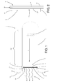
- the numeral 1 denotes as a whole an X-ray tube made in accordance with this invention.
- the X-ray tube comprises first a containment element 2 which is advantageously a glass bulb or the like.
- the containment element 2 also comprises an emission section 3, through which the X-rays produced in the tube 1 can be sent towards the zone where they are used (for example, for X-ray examination of a piece of timber).
- a cathode 4 and an anode 5 separated by a space are mounted inside the containment element 2.
- the cathode 4 may be made in the same way as the prior art cathodes.
- it is a heated coil able to emit electrons E due to a thermionic effect.
- the anode 5 like the prior art anodes, in this invention is made of material able to emit X-rays if struck by electrons E which have predetermined kinetic energy.
- the anode 5 comprises a first main face 6 which is substantially facing towards the cathode 4 and a second main face 7 which is facing the opposite way to the first face 6.
- the first main face 6 of the anode 5 does not need to be angled relative to the plane perpendicular to the direction extending from the cathode 4 towards the anode 5.
- the X-rays used from the X-ray tube 1 are not the backward rays as in the case of prior art tubes, but the forward rays, that is to say, the rays which, in practice, exit the second main face 7 of the anode 5.
- cooling means 8 are applied to the second main face 7 of the anode 5 to dissipate the heat generated during the production of the X-rays.
- the cooling means 8 comprise a heat conductor element 9 which is thermally coupled with the second main face 7 of the anode 5, and inside which a coolant fluid such as water flows.
- the main aspect of this invention is the fact that the cooling means 8 perform a dual function. They are also filter means 10 able to filter, based on the respective wavelengths, the X-rays emitted by the anode 5 (in Figure 1 the X-rays are represented by undulating arrows).
- the emission section 3 for the X-rays, through which the rays exit the containment element 2 is positioned in such a way that, in practice, it receives the X-rays emitted from the second main face 7 of the anode 5, that is to say, the forward rays, after they have passed through the filter means 10.
- the heat conductor element 9 in such a way that it houses a plurality of micro-channels 11 in which, in practice, a pressurised coolant liquid can flow with turbulent motion.
- micro-channels 11 refers to channels having at least one dimension which is not greater than several tenths of a millimetre.
- the heat conductor element 9 therefore has a "porous" structure in which the set of the various pores, which are all in fluid communication with each other, forms the set of micro-channels 11. In this way, on one hand a very large heat exchange surface area is obtained, and on the other hand a turbulent motion of the coolant fluid in the micro-channels 11 is generated. Both of these factors help to maximise heat removal by the coolant fluid.
- the heat conductor element 9 comprises at least one inlet section 12 and at least one outlet section 13 for the coolant fluid which are in fluid communication with the micro-channels 11 (in the embodiment illustrated the inlet section 12 and the outlet section 13 are two pipe fittings).
- the X-ray tube 1 is therefore also equipped with means for feeding a pressurised coolant fluid to the cooling means 8 (such as a pump - not illustrated - and suitable pipes 14).
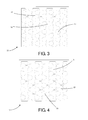
- the heat conductor element 9 advantageously comprises a plurality of flat plates 15, 16 packed one on top of another to form a lamellar pack 17 extending mainly flat.
- the lamellar pack 17 preferably extends mainly parallel with the plates ( Figure 2 ).
- two end plates 15 can be identified (to which the inlet section 12 and the outlet section 13 are connected) which are substantially without holes (with the exception of those for connecting the inlet section 12 and the outlet section 13 for the coolant fluid), as well as a plurality of inner plates 16.
- each inner plate 16 of the lamellar pack 17 comprises a plurality of through holes 18 which are distributed on its surface.
- each inner plate 16 has the shape of a grille with regular meshes.
- each hole 18 has a three-lobed shape formed by a hexagonal mesh with three circular areas 19 at alternate vertices of the hexagon.
- the holes 18 in each plate are only partly aligned with the holes 18 of the plates immediately adjacent to it.
- the meshes of each plate are offset relative to the meshes of the plates opposite it.
- each hole 18 in each of the inner plates 16 of the lamellar pack 17 is partly opposite at least two different holes 18 of each inner plate 16 directly facing it, thus putting them in fluid communication with each other.
- Figures 5 and 6 show the plates of Figures 3 and 4 coupled one on top of another. Solely to make the drawing easier to understand, in Figure 5 the plate of Figure 3 is positioned on top and is completely black, whilst the plate of Figure 4 is on the bottom. Moreover, in Figure 5 the arrow drawn with a dashed line indicates a possible path for the coolant fluid (when the arrow passes through a stretch of the black coloured plate, it means that the fluid flows into the hole 18 in the plate below).
- the lamellar pack 17 is obtained by alternating only two types of inner plates 16 (such as those of Figures 3 and 4 ).
- all of the plates have the same shape: that of Figure 4 is none other than the same plate as in Figure 3 but turned over.
- the plates 16 are also sized in such a way that the circular parts 19 of the meshes of one plate are precisely superposed on those of the adjacent meshes.
- the heat conductor element 9 is advantageously made of a material known for such properties, such as copper or beryllium or another metal.
- the thickness of the lamellar pack 17 is less than 1 cm whilst the thickness of each plate 15, 16 is several tenths of a millimetre or even less.
- this invention is one of the most simple embodiments possible. However, with the appropriate adjustments, this invention may also advantageously be applied with more complex embodiments, such as embodiments equipped with means for centring and focusing the electron flow and the X-rays, or embodiments with a rotating anode (in this case, obviously, a suitable embodiment of the inlet section 12 and the outlet section 13 will be required).
- Operation of the X-ray tube 1 according to this invention is substantially like that of conventional tubes as regards the generation of X-rays.
- the cathode 4 emits electrons E which are accelerated by the difference in potential ⁇ V applied between the cathode 4 and the anode 5, reaching a predetermined speed and thus acquiring a predetermined kinetic energy, a small part of which is converted into X-rays at the moment when the electrons E strike the anode 5.
- the forward rays generated pass through the heat conductor element 9 which eliminates the unwanted wavelengths, whilst the useful ones are able to reach the emission section 3 unhindered.
- the coolant fluid is circulated under pressure in the micro-channels 11, guaranteeing suitable cooling of the anode 5 which is thermally coupled with the heat conductor element 9.
- this invention allows the production of X-ray tubes which are much less expensive than conventional tubes.
Landscapes
- Physics & Mathematics (AREA)
- Fluid Mechanics (AREA)
- Spectroscopy & Molecular Physics (AREA)
- Engineering & Computer Science (AREA)
- General Engineering & Computer Science (AREA)
- High Energy & Nuclear Physics (AREA)
- X-Ray Techniques (AREA)
- Materials For Medical Uses (AREA)
- Rigid Pipes And Flexible Pipes (AREA)
- Rehabilitation Tools (AREA)
Description
- This invention relates to an X-ray tube for the production of X-rays, and in particular to an X-ray tube able to generate X-rays with relatively high intensity. This invention is aimed in particular at the production of X-ray tubes for use in plants which use X-rays to examine timber. Hereinafter reference is generally made to that sector. However, it shall be understood that this invention may without distinction be applied in any other sector and for any other purpose.
- Since they were invented, more than a century ago, X-ray tubes have usually consisted of a vacuum container (normally a glass bulb), housing a cathode (negative pole) and an anode (positive pole) between which, in practice, a relatively high direct current voltage is applied (even several kV).
- The anode is positioned at a predetermined distance from the cathode and consists of a heavy disk made of metal (such as tungsten, molybdenum or rhodium) able to emit X-rays if struck by electrons travelling with a predetermined kinetic energy as is explained in more detail below. The disk is positioned obliquely, in the sense that its main face facing towards the cathode is at an angle to the plane perpendicular to the direction linking the cathode and the anode.
- In turn, the cathode usually consists of a heated spiral which emits electrons due to a thermionic effect. Once emitted, the electrons are accelerated by the difference in potential existing between the anode and the cathode and then strike the metal disk. At the moment of impact a small part of their kinetic energy is transformed into X-rays according to a known process.
- The X-rays generated in this way, by themselves would propagate in all directions.
- However, the shape of the anode (a flat disk) means that most of the X-rays existing it propagate in a direction substantially perpendicular to the two faces of the disk. In particular, most of the rays propagate by exiting the opposite face of the disk to that which is facing the cathode (forward rays), whilst a significantly smaller part exits the latter (backward rays).
- Moreover, since, during operation, the anode is subject to significant heating, in industrial applications it has to be cooled. At present that is normally done by applying cooling means to the opposite face of the anode to that facing the cathode. The cooling means comprise a box-shaped metal element (usually made of steel) which is in thermal contact with the anode and in which a coolant liquid such as water flows. However, to guarantee correct heat dissipation, the dimensions and structure of the cooling means are such that practically all of the forward rays are absorbed by the box-shaped element or by the cooling water. Consequently, in prior art industrial X-ray tubes, the only rays usable are the backward rays. This is why the anode is positioned at an angle. Indeed, only in this way is it possible to direct the X-rays towards the outside of the tube without dissipating them in the cooling means and without striking the cathode.
- However, when the electrons strike the anode rays are generated which cover a wide range of different wavelengths (the actual range depends on the type of metal used to make the anode and the operating voltage, that is to say, the speed of the electrons at the moment of impact).
- However, at industrial level only some of the wavelengths are actually useful. For example, to examine timber, any rays with a lower frequency would not only be of no interest because unable to pass through wood, but must be avoided because they could saturate the detection sensor in the absence of wood.
- For that purpose, X-ray tubes currently on sale are fitted with a filter which intercepts the backward rays before they can get out.
- The filter consists of a metal plate (for example made of beryllium or copper) which is just a few millimetres thick and can absorb the wavelengths, of the X-rays emitted by the tube, which are not useful for the relative application.
- What is described above represents the aspects shared by all prior art solutions. However, it is important to consider that the X-ray tubes currently on the market may also have both electron flow confinement and concentration means, and X-ray confinement means. There are also prior art tubes with a rotating anode, which are designed to continuously vary the point of impact of the electrons on the anode. In any case, this invention may be applied, with the appropriate adjustments, to any X-ray tube.
- In light of the above, it seems clear that the main problem of prior art X-ray tubes is that of having low output. Only a small part of the X-rays produced are available for the relative uses. Consequently, in sectors which require high output (such as the X-ray examination of logs), normal commercial X-ray tubes are unsuitable and special extremely high output tubes with equally high costs must be used.
- Furthermore,
US 3 992 633 ,US 6 463 123 andUS 2 896 105 disclose X-ray tubes in which an anode made of a material able to emit X-rays if struck by electrons (E) with a predetermined kinetic energy, is mounted in a containment element, distanced from a cathode, and comprises a first main face which is substantially facing towards the cathode and a second main face which is facing the opposite way to the first face and is designed to emit the X-rays. Means are applied to the second main face of the anode both for cooling the anode and for filtering the emitted X-rays. Such means consists of a heat conductor element which is thermally coupled with the second face of the anode. -
US 3 992 633 andUS 6 463 123 also disclose that such means is equipped with inner channels in which, in use, a coolant liquid flows. - In this situation the technical purpose which forms the basis of this invention is to provide an X-ray tube which overcomes the above-mentioned disadvantages.
- In particular, the technical purpose of this invention is to provide an X-ray tube which, the operating parameters being equal, can supply X-rays with an intensity significantly greater than conventional X-ray tubes.
- It is also the technical purpose of this invention to provide an X-ray tube which, the output being equal, is less expensive than the conventional tubes.
- The technical purpose specified and the aims indicated are substantially achieved by an X-ray tube made as described in the appended claims.
- Further features and the advantages of this invention are more apparent in the detailed description, with reference to the accompanying drawings which illustrate several preferred, non-limiting embodiments of an X-ray tube, in which:
-
Figure 1 is a schematic view of an X-ray tube made in accordance with this invention; -
Figure 2 is an enlarged detail of the tube ofFigure 1 ; -
Figure 3 is a schematic top view of a plate which is part of a component part of the X-ray tube ofFigure 1 ; -
Figure 4 is a schematic top view of another plate; -
Figure 5 is a top view of the plates ofFigures 3 and 4 in which the plates are coupled together; and -
Figure 6 is a schematic front view of the plates ofFigure 5 . - With reference to the accompanying drawings the
numeral 1 denotes as a whole an X-ray tube made in accordance with this invention. - Similarly to prior art X-ray tubes, the X-ray tube according to this invention comprises first a containment element 2 which is advantageously a glass bulb or the like. The containment element 2 also comprises an emission section 3, through which the X-rays produced in the
tube 1 can be sent towards the zone where they are used (for example, for X-ray examination of a piece of timber). As shown inFigure 1 , a cathode 4 and ananode 5 separated by a space are mounted inside the containment element 2. - The cathode 4 may be made in the same way as the prior art cathodes. In
Figure 1 , in particular, it is a heated coil able to emit electrons E due to a thermionic effect. - In contrast, the
anode 5, like the prior art anodes, in this invention is made of material able to emit X-rays if struck by electrons E which have predetermined kinetic energy. Theanode 5 comprises a firstmain face 6 which is substantially facing towards the cathode 4 and a second main face 7 which is facing the opposite way to thefirst face 6. - According to this invention, the first
main face 6 of theanode 5 does not need to be angled relative to the plane perpendicular to the direction extending from the cathode 4 towards theanode 5. As is described in more detail below, according to this invention, the X-rays used from theX-ray tube 1 are not the backward rays as in the case of prior art tubes, but the forward rays, that is to say, the rays which, in practice, exit the second main face 7 of theanode 5. - Advantageously, cooling means 8 are applied to the second main face 7 of the
anode 5 to dissipate the heat generated during the production of the X-rays. The cooling means 8 comprise aheat conductor element 9 which is thermally coupled with the second main face 7 of theanode 5, and inside which a coolant fluid such as water flows. - The main aspect of this invention is the fact that the cooling means 8 perform a dual function. They are also filter means 10 able to filter, based on the respective wavelengths, the X-rays emitted by the anode 5 (in
Figure 1 the X-rays are represented by undulating arrows). - Thanks to that innovative embodiment, in accordance with this invention the emission section 3 for the X-rays, through which the rays exit the containment element 2, is positioned in such a way that, in practice, it receives the X-rays emitted from the second main face 7 of the
anode 5, that is to say, the forward rays, after they have passed through the filter means 10. - In the preferred embodiment this is achieved by making the
heat conductor element 9 in such a way that it houses a plurality of micro-channels 11 in which, in practice, a pressurised coolant liquid can flow with turbulent motion. Within the scope of this invention, the term micro-channels 11 refers to channels having at least one dimension which is not greater than several tenths of a millimetre. - In the ideal embodiment, the
heat conductor element 9 therefore has a "porous" structure in which the set of the various pores, which are all in fluid communication with each other, forms the set of micro-channels 11. In this way, on one hand a very large heat exchange surface area is obtained, and on the other hand a turbulent motion of the coolant fluid in the micro-channels 11 is generated. Both of these factors help to maximise heat removal by the coolant fluid. - Moreover, to allow circulation of the fluid, the
heat conductor element 9 comprises at least oneinlet section 12 and at least oneoutlet section 13 for the coolant fluid which are in fluid communication with the micro-channels 11 (in the embodiment illustrated theinlet section 12 and theoutlet section 13 are two pipe fittings). In more complete embodiments of this invention, theX-ray tube 1 is therefore also equipped with means for feeding a pressurised coolant fluid to the cooling means 8 (such as a pump - not illustrated - and suitable pipes 14). - In the preferred embodiment, the
heat conductor element 9 advantageously comprises a plurality offlat plates lamellar pack 17 extending mainly flat. Moreover, thelamellar pack 17 preferably extends mainly parallel with the plates (Figure 2 ). - In the
lamellar pack 17 twoend plates 15 can be identified (to which theinlet section 12 and theoutlet section 13 are connected) which are substantially without holes (with the exception of those for connecting theinlet section 12 and theoutlet section 13 for the coolant fluid), as well as a plurality ofinner plates 16. - As shown in
Figures 3 and 4 , eachinner plate 16 of thelamellar pack 17 comprises a plurality of throughholes 18 which are distributed on its surface. For that purpose, advantageously eachinner plate 16 has the shape of a grille with regular meshes. In the embodiment illustrated eachhole 18 has a three-lobed shape formed by a hexagonal mesh with threecircular areas 19 at alternate vertices of the hexagon. - To form the micro-channels 11, once the pack has been made, the
holes 18 in each plate are only partly aligned with theholes 18 of the plates immediately adjacent to it. In particular if the shape and size of the meshes is the same for all of the plates, in thelamellar pack 17 the meshes of each plate are offset relative to the meshes of the plates opposite it. - Moreover, advantageously, each
hole 18 in each of theinner plates 16 of thelamellar pack 17 is partly opposite at least twodifferent holes 18 of eachinner plate 16 directly facing it, thus putting them in fluid communication with each other. - That situation is schematically illustrated in
Figures 5 and 6 which show the plates ofFigures 3 and 4 coupled one on top of another. Solely to make the drawing easier to understand, inFigure 5 the plate ofFigure 3 is positioned on top and is completely black, whilst the plate ofFigure 4 is on the bottom. Moreover, inFigure 5 the arrow drawn with a dashed line indicates a possible path for the coolant fluid (when the arrow passes through a stretch of the black coloured plate, it means that the fluid flows into thehole 18 in the plate below). - Moreover, in the preferred embodiment, the
lamellar pack 17 is obtained by alternating only two types of inner plates 16 (such as those ofFigures 3 and 4 ). Advantageously, in the embodiment illustrated all of the plates have the same shape: that ofFigure 4 is none other than the same plate as inFigure 3 but turned over. Theplates 16 are also sized in such a way that thecircular parts 19 of the meshes of one plate are precisely superposed on those of the adjacent meshes. - Moreover, to obtain a correct filtering effect on the X-rays, the
heat conductor element 9 is advantageously made of a material known for such properties, such as copper or beryllium or another metal. Advantageously, in the preferred embodiments the thickness of thelamellar pack 17 is less than 1 cm whilst the thickness of eachplate - As already indicated, the embodiment of this invention described above is one of the most simple embodiments possible. However, with the appropriate adjustments, this invention may also advantageously be applied with more complex embodiments, such as embodiments equipped with means for centring and focusing the electron flow and the X-rays, or embodiments with a rotating anode (in this case, obviously, a suitable embodiment of the
inlet section 12 and theoutlet section 13 will be required). - Operation of the
X-ray tube 1 according to this invention is substantially like that of conventional tubes as regards the generation of X-rays. The cathode 4 emits electrons E which are accelerated by the difference in potential ΔV applied between the cathode 4 and theanode 5, reaching a predetermined speed and thus acquiring a predetermined kinetic energy, a small part of which is converted into X-rays at the moment when the electrons E strike theanode 5. - The forward rays generated pass through the
heat conductor element 9 which eliminates the unwanted wavelengths, whilst the useful ones are able to reach the emission section 3 unhindered. At the same time, the coolant fluid is circulated under pressure in the micro-channels 11, guaranteeing suitable cooling of theanode 5 which is thermally coupled with theheat conductor element 9. This invention brings important advantages. - Thanks to this invention it was possible to provide an X-ray tube which, the absorbed power being equal, guarantees available output in terms of X-rays that is significantly higher, that is to say, tubes which are considerably more efficient.
- Alternatively, the available output being equal, this invention allows the production of X-ray tubes which are much less expensive than conventional tubes.
- Finally, it should be noticed that this invention is relatively easy to produce and that even the cost linked to implementing the invention is not very high.
Claims (7)
- An X-ray tube comprising:a containment element (2) comprising an X-ray emission section (3);a cathode (4) mounted in the containment element (2);an anode (5) mounted in the containment element (2), distanced from the cathode (4) and made of material able to emit X-rays if struck by electrons (E) which have a predetermined kinetic energy, the anode (5) comprising a first main face (6) which is substantially facing towards the cathode (4) and a second main face (7) which is facing the opposite way to the first face (6);cooling means (8) applied to the second main face (7) of the anode (5); andfilter means (10) for filtering, based on respective wavelengths, the X-rays emitted by the anode (5);the X-ray emission section (3) being positioned in such a way that, in practice, it receives the X-rays emitted by the second main face (7) of the anode (5) after they have passed through the filter means (10);the filter means (10) consisting of the cooling means (8) and both the cooling means (8) and the filter means (10) consisting of a heat conductor element (9) which is thermally coupled with the second face (7) of the anode (5) and which is equipped with a plurality of inner micro-channels (11) in which, in practice, a pressurised coolant liquid can flow with a turbulent motion;the X-ray tube being characterised in that the heat conductor element (9) comprises a plurality of flat plates packed one on top of another to form a lamellar pack (17) extending mainly flat, each inner plate (16) of the lamellar pack (3) comprising a plurality of through-holes (18) distributed over its surface, the holes (18) of each plate being only partly aligned with the holes (18) of the immediately adjacent plates, the set of holes (18) of the various plates forming said plurality of micro-channels (11).
- The X-ray tube according to claim 1, characterised in that each hole (18) in each of the inner plates (16) of the lamellar pack (17) is partly opposite at least two different holes (18) of each inner plate (16) directly facing it, thus putting them in fluid communication with each other.
- The X-ray tube according to claim 1 or 2, characterised in that the inner plates (16) of the lamellar pack (17) have a grille shape with regular meshes, the meshes of each plate being offset relative to the meshes of the plates opposite it.
- The X-ray tube according to any of the claims from 1 to 2, characterised in that the lamellar pack (17) is less than 1 cm thick and each plate is around several tenths of a millimetre thick.
- The X-ray tube according to any of the claims from 1 to 3, characterised in that the heat conductor element (9) is made of metal.
- The X-ray tube according to any of the claim from 1 to 5, characterised in that the heat conductor element (9) also comprises at least one inlet section (12) and at least one outlet section (13) for the coolant fluid, said sections being in communication with the micro-channels (11).
- The X-ray tube according to any of the foregoing claims, characterised in that it also comprises means for feeding a pressurised coolant fluid to the cooling means (8).
Applications Claiming Priority (2)
| Application Number | Priority Date | Filing Date | Title |
|---|---|---|---|
| ITVR2010A000016A IT1398464B1 (en) | 2010-02-02 | 2010-02-02 | RADIOGEN TUBE |
| PCT/IB2011/050411 WO2011095925A1 (en) | 2010-02-02 | 2011-01-31 | X-ray tube |
Publications (2)
| Publication Number | Publication Date |
|---|---|
| EP2532018A1 EP2532018A1 (en) | 2012-12-12 |
| EP2532018B1 true EP2532018B1 (en) | 2015-04-15 |
Family
ID=42670323
Family Applications (1)
| Application Number | Title | Priority Date | Filing Date |
|---|---|---|---|
| EP11708089.5A Not-in-force EP2532018B1 (en) | 2010-02-02 | 2011-01-31 | X-ray tube |
Country Status (7)
| Country | Link |
|---|---|
| US (1) | US20120328081A1 (en) |
| EP (1) | EP2532018B1 (en) |
| JP (1) | JP5737527B2 (en) |
| CN (1) | CN102741967B (en) |
| IT (1) | IT1398464B1 (en) |
| RU (1) | RU2570357C2 (en) |
| WO (1) | WO2011095925A1 (en) |
Families Citing this family (4)
| Publication number | Priority date | Publication date | Assignee | Title |
|---|---|---|---|---|
| KR20150051820A (en) * | 2013-11-05 | 2015-05-13 | 삼성전자주식회사 | Penetrative plate X-ray generating apparatus and X-ray imaging system |
| US20180151324A1 (en) * | 2016-11-26 | 2018-05-31 | Varex Imaging Corporation | Heat sink for x-ray tube anode |
| CN107546090B (en) * | 2017-09-19 | 2024-04-05 | 同方威视技术股份有限公司 | X-ray conversion target |
| CN116844931B (en) * | 2023-08-31 | 2023-11-17 | 昆山医源医疗技术有限公司 | X-ray tube, cathode chassis assembly and tube core assembly thereof |
Family Cites Families (15)
| Publication number | Priority date | Publication date | Assignee | Title |
|---|---|---|---|---|
| DE718031C (en) * | 1939-03-10 | 1942-02-28 | Siemens Reiniger Werke Ag | X-ray tube anode with circulation cooling for high performance |
| US2896105A (en) * | 1956-01-02 | 1959-07-21 | Hosemann Rolf | High capacity x-ray tube |
| DE1033343B (en) * | 1956-01-02 | 1958-07-03 | Dr Phil Nat Rolf Hosemann | X-ray tubes with high radiation output |
| CA1007767A (en) * | 1973-09-04 | 1977-03-29 | Machlett Laboratories | Broad aperture x-ray generator |
| US3992633A (en) * | 1973-09-04 | 1976-11-16 | The Machlett Laboratories, Incorporated | Broad aperture X-ray generator |
| US4781033A (en) * | 1987-07-16 | 1988-11-01 | Apd Cryogenics | Heat exchanger for a fast cooldown cryostat |
| US5058665A (en) * | 1989-03-28 | 1991-10-22 | Aisin Seiki Kabushiki Kaisha | Stacked-plate type heat exchanger |
| GB8910241D0 (en) * | 1989-05-04 | 1989-06-21 | Secretary Trade Ind Brit | Heat exchangers |
| US5185774A (en) * | 1990-11-23 | 1993-02-09 | Pxt Technology, Inc. | X-ray tube construction |
| US5901783A (en) * | 1995-10-12 | 1999-05-11 | Croyogen, Inc. | Cryogenic heat exchanger |
| US6463123B1 (en) * | 2000-11-09 | 2002-10-08 | Steris Inc. | Target for production of x-rays |
| US6661876B2 (en) * | 2001-07-30 | 2003-12-09 | Moxtek, Inc. | Mobile miniature X-ray source |
| GB0309371D0 (en) * | 2003-04-25 | 2003-06-04 | Cxr Ltd | X-Ray tubes |
| WO2006111941A2 (en) * | 2005-04-22 | 2006-10-26 | Ferrotec (Usa) Corporation | High efficiency fluid heat exchanger and method of manufacture |
| WO2007105736A1 (en) * | 2006-03-13 | 2007-09-20 | Ngk Insulators, Ltd. | Honeycomb catalyst structure |
-
2010
- 2010-02-02 IT ITVR2010A000016A patent/IT1398464B1/en active
-
2011
- 2011-01-31 CN CN201180008052.8A patent/CN102741967B/en not_active Expired - Fee Related
- 2011-01-31 WO PCT/IB2011/050411 patent/WO2011095925A1/en not_active Ceased
- 2011-01-31 US US13/576,593 patent/US20120328081A1/en not_active Abandoned
- 2011-01-31 EP EP11708089.5A patent/EP2532018B1/en not_active Not-in-force
- 2011-01-31 RU RU2012137212/07A patent/RU2570357C2/en not_active IP Right Cessation
- 2011-01-31 JP JP2012550556A patent/JP5737527B2/en not_active Expired - Fee Related
Also Published As
| Publication number | Publication date |
|---|---|
| CN102741967B (en) | 2015-11-25 |
| ITVR20100016A1 (en) | 2011-08-03 |
| JP2013519191A (en) | 2013-05-23 |
| JP5737527B2 (en) | 2015-06-17 |
| RU2570357C2 (en) | 2015-12-10 |
| US20120328081A1 (en) | 2012-12-27 |
| EP2532018A1 (en) | 2012-12-12 |
| RU2012137212A (en) | 2014-03-10 |
| IT1398464B1 (en) | 2013-02-22 |
| CN102741967A (en) | 2012-10-17 |
| WO2011095925A1 (en) | 2011-08-11 |
Similar Documents
| Publication | Publication Date | Title |
|---|---|---|
| CN103903940B (en) | A kind of apparatus and method for producing distributed X-ray | |
| EP2532018B1 (en) | X-ray tube | |
| US6580780B1 (en) | Cooling system for stationary anode x-ray tubes | |
| US6438208B1 (en) | Large surface area x-ray tube window and window cooling plenum | |
| CN105788695B (en) | A kind of high-power electron irradiation accelerator X-ray conversion target | |
| WO2023050976A1 (en) | Swing-type high-power x-ray conversion target device | |
| JP3887395B2 (en) | X-ray generator | |
| CN109844897B (en) | Heat sinks for X-ray tube anodes | |
| US12482626B2 (en) | X-ray tube with corrugated wall | |
| CN104362063B (en) | Integrally-packaged carbon nano-radiation source for computed tomography (CT) imaging system | |
| JP4238245B2 (en) | X-ray generation method and X-ray generation apparatus | |
| JP3866558B2 (en) | X-ray generator | |
| US7668298B2 (en) | System and method for collecting backscattered electrons in an x-ray tube | |
| US3296476A (en) | X-ray tube | |
| CN216120202U (en) | Swing type high-power X-ray conversion target device | |
| US20180206319A1 (en) | Modular laser-produced plasma x-ray system | |
| CN112512196B (en) | Array X-ray source and X-ray imaging equipment | |
| CN210535622U (en) | A kind of X-ray tube anode cooling structure | |
| SU1434508A1 (en) | X-ray tube | |
| CN110828267A (en) | A super-evaporative cooling anode | |
| JP5548189B2 (en) | X-ray generator target and processing method thereof | |
| CN212810234U (en) | Grid type X-ray conversion target | |
| CN216700421U (en) | Radiation processing device | |
| JP5200259B2 (en) | X-ray tube | |
| CN203760419U (en) | Cooling system-equipped industrial X ray tube anode |
Legal Events
| Date | Code | Title | Description |
|---|---|---|---|
| PUAI | Public reference made under article 153(3) epc to a published international application that has entered the european phase |
Free format text: ORIGINAL CODE: 0009012 |
|
| 17P | Request for examination filed |
Effective date: 20120716 |
|
| AK | Designated contracting states |
Kind code of ref document: A1 Designated state(s): AL AT BE BG CH CY CZ DE DK EE ES FI FR GB GR HR HU IE IS IT LI LT LU LV MC MK MT NL NO PL PT RO RS SE SI SK SM TR |
|
| DAX | Request for extension of the european patent (deleted) | ||
| GRAP | Despatch of communication of intention to grant a patent |
Free format text: ORIGINAL CODE: EPIDOSNIGR1 |
|
| INTG | Intention to grant announced |
Effective date: 20141112 |
|
| GRAS | Grant fee paid |
Free format text: ORIGINAL CODE: EPIDOSNIGR3 |
|
| GRAA | (expected) grant |
Free format text: ORIGINAL CODE: 0009210 |
|
| AK | Designated contracting states |
Kind code of ref document: B1 Designated state(s): AL AT BE BG CH CY CZ DE DK EE ES FI FR GB GR HR HU IE IS IT LI LT LU LV MC MK MT NL NO PL PT RO RS SE SI SK SM TR |
|
| REG | Reference to a national code |
Ref country code: GB Ref legal event code: FG4D Ref country code: CH Ref legal event code: EP |
|
| REG | Reference to a national code |
Ref country code: IE Ref legal event code: FG4D |
|
| REG | Reference to a national code |
Ref country code: AT Ref legal event code: REF Ref document number: 722385 Country of ref document: AT Kind code of ref document: T Effective date: 20150515 |
|
| REG | Reference to a national code |
Ref country code: DE Ref legal event code: R096 Ref document number: 602011015638 Country of ref document: DE Effective date: 20150528 |
|
| REG | Reference to a national code |
Ref country code: NL Ref legal event code: VDEP Effective date: 20150415 |
|
| REG | Reference to a national code |
Ref country code: AT Ref legal event code: MK05 Ref document number: 722385 Country of ref document: AT Kind code of ref document: T Effective date: 20150415 |
|
| REG | Reference to a national code |
Ref country code: LT Ref legal event code: MG4D |
|
| PG25 | Lapsed in a contracting state [announced via postgrant information from national office to epo] |
Ref country code: NL Free format text: LAPSE BECAUSE OF FAILURE TO SUBMIT A TRANSLATION OF THE DESCRIPTION OR TO PAY THE FEE WITHIN THE PRESCRIBED TIME-LIMIT Effective date: 20150415 |
|
| PG25 | Lapsed in a contracting state [announced via postgrant information from national office to epo] |
Ref country code: ES Free format text: LAPSE BECAUSE OF FAILURE TO SUBMIT A TRANSLATION OF THE DESCRIPTION OR TO PAY THE FEE WITHIN THE PRESCRIBED TIME-LIMIT Effective date: 20150415 Ref country code: NO Free format text: LAPSE BECAUSE OF FAILURE TO SUBMIT A TRANSLATION OF THE DESCRIPTION OR TO PAY THE FEE WITHIN THE PRESCRIBED TIME-LIMIT Effective date: 20150715 Ref country code: HR Free format text: LAPSE BECAUSE OF FAILURE TO SUBMIT A TRANSLATION OF THE DESCRIPTION OR TO PAY THE FEE WITHIN THE PRESCRIBED TIME-LIMIT Effective date: 20150415 Ref country code: LT Free format text: LAPSE BECAUSE OF FAILURE TO SUBMIT A TRANSLATION OF THE DESCRIPTION OR TO PAY THE FEE WITHIN THE PRESCRIBED TIME-LIMIT Effective date: 20150415 Ref country code: FI Free format text: LAPSE BECAUSE OF FAILURE TO SUBMIT A TRANSLATION OF THE DESCRIPTION OR TO PAY THE FEE WITHIN THE PRESCRIBED TIME-LIMIT Effective date: 20150415 Ref country code: PT Free format text: LAPSE BECAUSE OF FAILURE TO SUBMIT A TRANSLATION OF THE DESCRIPTION OR TO PAY THE FEE WITHIN THE PRESCRIBED TIME-LIMIT Effective date: 20150817 |
|
| PG25 | Lapsed in a contracting state [announced via postgrant information from national office to epo] |
Ref country code: IS Free format text: LAPSE BECAUSE OF FAILURE TO SUBMIT A TRANSLATION OF THE DESCRIPTION OR TO PAY THE FEE WITHIN THE PRESCRIBED TIME-LIMIT Effective date: 20150815 Ref country code: LV Free format text: LAPSE BECAUSE OF FAILURE TO SUBMIT A TRANSLATION OF THE DESCRIPTION OR TO PAY THE FEE WITHIN THE PRESCRIBED TIME-LIMIT Effective date: 20150415 Ref country code: GR Free format text: LAPSE BECAUSE OF FAILURE TO SUBMIT A TRANSLATION OF THE DESCRIPTION OR TO PAY THE FEE WITHIN THE PRESCRIBED TIME-LIMIT Effective date: 20150716 Ref country code: AT Free format text: LAPSE BECAUSE OF FAILURE TO SUBMIT A TRANSLATION OF THE DESCRIPTION OR TO PAY THE FEE WITHIN THE PRESCRIBED TIME-LIMIT Effective date: 20150415 Ref country code: RS Free format text: LAPSE BECAUSE OF FAILURE TO SUBMIT A TRANSLATION OF THE DESCRIPTION OR TO PAY THE FEE WITHIN THE PRESCRIBED TIME-LIMIT Effective date: 20150415 |
|
| REG | Reference to a national code |
Ref country code: DE Ref legal event code: R097 Ref document number: 602011015638 Country of ref document: DE |
|
| REG | Reference to a national code |
Ref country code: FR Ref legal event code: PLFP Year of fee payment: 6 |
|
| PG25 | Lapsed in a contracting state [announced via postgrant information from national office to epo] |
Ref country code: DK Free format text: LAPSE BECAUSE OF FAILURE TO SUBMIT A TRANSLATION OF THE DESCRIPTION OR TO PAY THE FEE WITHIN THE PRESCRIBED TIME-LIMIT Effective date: 20150415 Ref country code: EE Free format text: LAPSE BECAUSE OF FAILURE TO SUBMIT A TRANSLATION OF THE DESCRIPTION OR TO PAY THE FEE WITHIN THE PRESCRIBED TIME-LIMIT Effective date: 20150415 |
|
| PLBE | No opposition filed within time limit |
Free format text: ORIGINAL CODE: 0009261 |
|
| STAA | Information on the status of an ep patent application or granted ep patent |
Free format text: STATUS: NO OPPOSITION FILED WITHIN TIME LIMIT |
|
| PG25 | Lapsed in a contracting state [announced via postgrant information from national office to epo] |
Ref country code: CZ Free format text: LAPSE BECAUSE OF FAILURE TO SUBMIT A TRANSLATION OF THE DESCRIPTION OR TO PAY THE FEE WITHIN THE PRESCRIBED TIME-LIMIT Effective date: 20150415 Ref country code: RO Free format text: LAPSE BECAUSE OF NON-PAYMENT OF DUE FEES Effective date: 20150415 Ref country code: SK Free format text: LAPSE BECAUSE OF FAILURE TO SUBMIT A TRANSLATION OF THE DESCRIPTION OR TO PAY THE FEE WITHIN THE PRESCRIBED TIME-LIMIT Effective date: 20150415 Ref country code: PL Free format text: LAPSE BECAUSE OF FAILURE TO SUBMIT A TRANSLATION OF THE DESCRIPTION OR TO PAY THE FEE WITHIN THE PRESCRIBED TIME-LIMIT Effective date: 20150415 |
|
| 26N | No opposition filed |
Effective date: 20160118 |
|
| PG25 | Lapsed in a contracting state [announced via postgrant information from national office to epo] |
Ref country code: IT Free format text: LAPSE BECAUSE OF FAILURE TO SUBMIT A TRANSLATION OF THE DESCRIPTION OR TO PAY THE FEE WITHIN THE PRESCRIBED TIME-LIMIT Effective date: 20150415 |
|
| PGFP | Annual fee paid to national office [announced via postgrant information from national office to epo] |
Ref country code: DE Payment date: 20160204 Year of fee payment: 6 Ref country code: CH Payment date: 20160128 Year of fee payment: 6 |
|
| PG25 | Lapsed in a contracting state [announced via postgrant information from national office to epo] |
Ref country code: SI Free format text: LAPSE BECAUSE OF FAILURE TO SUBMIT A TRANSLATION OF THE DESCRIPTION OR TO PAY THE FEE WITHIN THE PRESCRIBED TIME-LIMIT Effective date: 20150415 Ref country code: BE Free format text: LAPSE BECAUSE OF NON-PAYMENT OF DUE FEES Effective date: 20160131 |
|
| PGFP | Annual fee paid to national office [announced via postgrant information from national office to epo] |
Ref country code: GB Payment date: 20160204 Year of fee payment: 6 Ref country code: FR Payment date: 20160121 Year of fee payment: 6 |
|
| PG25 | Lapsed in a contracting state [announced via postgrant information from national office to epo] |
Ref country code: BE Free format text: LAPSE BECAUSE OF FAILURE TO SUBMIT A TRANSLATION OF THE DESCRIPTION OR TO PAY THE FEE WITHIN THE PRESCRIBED TIME-LIMIT Effective date: 20150415 Ref country code: LU Free format text: LAPSE BECAUSE OF FAILURE TO SUBMIT A TRANSLATION OF THE DESCRIPTION OR TO PAY THE FEE WITHIN THE PRESCRIBED TIME-LIMIT Effective date: 20160131 |
|
| PG25 | Lapsed in a contracting state [announced via postgrant information from national office to epo] |
Ref country code: MC Free format text: LAPSE BECAUSE OF FAILURE TO SUBMIT A TRANSLATION OF THE DESCRIPTION OR TO PAY THE FEE WITHIN THE PRESCRIBED TIME-LIMIT Effective date: 20150415 |
|
| REG | Reference to a national code |
Ref country code: IE Ref legal event code: MM4A |
|
| PG25 | Lapsed in a contracting state [announced via postgrant information from national office to epo] |
Ref country code: IE Free format text: LAPSE BECAUSE OF NON-PAYMENT OF DUE FEES Effective date: 20160131 |
|
| PG25 | Lapsed in a contracting state [announced via postgrant information from national office to epo] |
Ref country code: SE Free format text: LAPSE BECAUSE OF FAILURE TO SUBMIT A TRANSLATION OF THE DESCRIPTION OR TO PAY THE FEE WITHIN THE PRESCRIBED TIME-LIMIT Effective date: 20150415 |
|
| REG | Reference to a national code |
Ref country code: DE Ref legal event code: R119 Ref document number: 602011015638 Country of ref document: DE |
|
| PG25 | Lapsed in a contracting state [announced via postgrant information from national office to epo] |
Ref country code: MT Free format text: LAPSE BECAUSE OF FAILURE TO SUBMIT A TRANSLATION OF THE DESCRIPTION OR TO PAY THE FEE WITHIN THE PRESCRIBED TIME-LIMIT Effective date: 20150415 |
|
| REG | Reference to a national code |
Ref country code: CH Ref legal event code: PL |
|
| GBPC | Gb: european patent ceased through non-payment of renewal fee |
Effective date: 20170131 |
|
| REG | Reference to a national code |
Ref country code: FR Ref legal event code: ST Effective date: 20170929 |
|
| PG25 | Lapsed in a contracting state [announced via postgrant information from national office to epo] |
Ref country code: LI Free format text: LAPSE BECAUSE OF NON-PAYMENT OF DUE FEES Effective date: 20170131 Ref country code: FR Free format text: LAPSE BECAUSE OF NON-PAYMENT OF DUE FEES Effective date: 20170131 Ref country code: CH Free format text: LAPSE BECAUSE OF NON-PAYMENT OF DUE FEES Effective date: 20170131 |
|
| PG25 | Lapsed in a contracting state [announced via postgrant information from national office to epo] |
Ref country code: GB Free format text: LAPSE BECAUSE OF NON-PAYMENT OF DUE FEES Effective date: 20170131 Ref country code: DE Free format text: LAPSE BECAUSE OF NON-PAYMENT OF DUE FEES Effective date: 20170801 |
|
| PG25 | Lapsed in a contracting state [announced via postgrant information from national office to epo] |
Ref country code: HU Free format text: LAPSE BECAUSE OF FAILURE TO SUBMIT A TRANSLATION OF THE DESCRIPTION OR TO PAY THE FEE WITHIN THE PRESCRIBED TIME-LIMIT; INVALID AB INITIO Effective date: 20110131 Ref country code: SM Free format text: LAPSE BECAUSE OF FAILURE TO SUBMIT A TRANSLATION OF THE DESCRIPTION OR TO PAY THE FEE WITHIN THE PRESCRIBED TIME-LIMIT Effective date: 20150415 Ref country code: CY Free format text: LAPSE BECAUSE OF FAILURE TO SUBMIT A TRANSLATION OF THE DESCRIPTION OR TO PAY THE FEE WITHIN THE PRESCRIBED TIME-LIMIT Effective date: 20150415 |
|
| PG25 | Lapsed in a contracting state [announced via postgrant information from national office to epo] |
Ref country code: MK Free format text: LAPSE BECAUSE OF FAILURE TO SUBMIT A TRANSLATION OF THE DESCRIPTION OR TO PAY THE FEE WITHIN THE PRESCRIBED TIME-LIMIT Effective date: 20150415 Ref country code: TR Free format text: LAPSE BECAUSE OF FAILURE TO SUBMIT A TRANSLATION OF THE DESCRIPTION OR TO PAY THE FEE WITHIN THE PRESCRIBED TIME-LIMIT Effective date: 20150415 |
|
| PG25 | Lapsed in a contracting state [announced via postgrant information from national office to epo] |
Ref country code: BG Free format text: LAPSE BECAUSE OF FAILURE TO SUBMIT A TRANSLATION OF THE DESCRIPTION OR TO PAY THE FEE WITHIN THE PRESCRIBED TIME-LIMIT Effective date: 20150415 |
|
| PG25 | Lapsed in a contracting state [announced via postgrant information from national office to epo] |
Ref country code: AL Free format text: LAPSE BECAUSE OF FAILURE TO SUBMIT A TRANSLATION OF THE DESCRIPTION OR TO PAY THE FEE WITHIN THE PRESCRIBED TIME-LIMIT Effective date: 20150415 |