EP2531877B1 - Glasfaserkabelbündel mit versetzten verbindern - Google Patents
Glasfaserkabelbündel mit versetzten verbindern Download PDFInfo
- Publication number
- EP2531877B1 EP2531877B1 EP11740299.0A EP11740299A EP2531877B1 EP 2531877 B1 EP2531877 B1 EP 2531877B1 EP 11740299 A EP11740299 A EP 11740299A EP 2531877 B1 EP2531877 B1 EP 2531877B1
- Authority
- EP
- European Patent Office
- Prior art keywords
- fiber optic
- group
- optic cable
- cable bundle
- optic cables
- Prior art date
- Legal status (The legal status is an assumption and is not a legal conclusion. Google has not performed a legal analysis and makes no representation as to the accuracy of the status listed.)
- Not-in-force
Links
- 239000000835 fiber Substances 0.000 title claims description 296
- 239000011230 binding agent Substances 0.000 claims description 31
- 239000013307 optical fiber Substances 0.000 claims description 20
- 239000004760 aramid Substances 0.000 claims description 3
- 229920003235 aromatic polyamide Polymers 0.000 claims description 3
- 239000000463 material Substances 0.000 description 35
- 239000004677 Nylon Substances 0.000 description 8
- 229920001778 nylon Polymers 0.000 description 8
- -1 polyethylenes Polymers 0.000 description 8
- 238000005253 cladding Methods 0.000 description 7
- 230000003287 optical effect Effects 0.000 description 6
- 239000011248 coating agent Substances 0.000 description 5
- 238000000576 coating method Methods 0.000 description 5
- VYPSYNLAJGMNEJ-UHFFFAOYSA-N Silicium dioxide Chemical compound O=[Si]=O VYPSYNLAJGMNEJ-UHFFFAOYSA-N 0.000 description 4
- 229920000642 polymer Polymers 0.000 description 4
- 229920000106 Liquid crystal polymer Polymers 0.000 description 3
- 239000004977 Liquid-crystal polymers (LCPs) Substances 0.000 description 3
- 239000004698 Polyethylene Substances 0.000 description 3
- 239000000654 additive Substances 0.000 description 3
- 229920000728 polyester Polymers 0.000 description 3
- 229920000573 polyethylene Polymers 0.000 description 3
- 239000004800 polyvinyl chloride Substances 0.000 description 3
- 239000004743 Polypropylene Substances 0.000 description 2
- 238000005452 bending Methods 0.000 description 2
- DQXBYHZEEUGOBF-UHFFFAOYSA-N but-3-enoic acid;ethene Chemical compound C=C.OC(=O)CC=C DQXBYHZEEUGOBF-UHFFFAOYSA-N 0.000 description 2
- 238000004891 communication Methods 0.000 description 2
- 238000010276 construction Methods 0.000 description 2
- 229920001577 copolymer Polymers 0.000 description 2
- 239000005038 ethylene vinyl acetate Substances 0.000 description 2
- 238000001125 extrusion Methods 0.000 description 2
- 230000006870 function Effects 0.000 description 2
- 239000011521 glass Substances 0.000 description 2
- 238000002844 melting Methods 0.000 description 2
- 230000008018 melting Effects 0.000 description 2
- 229920001200 poly(ethylene-vinyl acetate) Polymers 0.000 description 2
- 229920001155 polypropylene Polymers 0.000 description 2
- 239000004814 polyurethane Substances 0.000 description 2
- 229920002635 polyurethane Polymers 0.000 description 2
- 229920000915 polyvinyl chloride Polymers 0.000 description 2
- 229920002981 polyvinylidene fluoride Polymers 0.000 description 2
- 239000000377 silicon dioxide Substances 0.000 description 2
- 239000004593 Epoxy Substances 0.000 description 1
- 229920000271 Kevlar® Polymers 0.000 description 1
- 239000004696 Poly ether ether ketone Substances 0.000 description 1
- 239000004952 Polyamide Substances 0.000 description 1
- 239000004697 Polyetherimide Substances 0.000 description 1
- 239000004734 Polyphenylene sulfide Substances 0.000 description 1
- 239000004793 Polystyrene Substances 0.000 description 1
- PPBRXRYQALVLMV-UHFFFAOYSA-N Styrene Natural products C=CC1=CC=CC=C1 PPBRXRYQALVLMV-UHFFFAOYSA-N 0.000 description 1
- 239000002390 adhesive tape Substances 0.000 description 1
- 230000004075 alteration Effects 0.000 description 1
- 239000007822 coupling agent Substances 0.000 description 1
- 235000004879 dioscorea Nutrition 0.000 description 1
- 125000003700 epoxy group Chemical group 0.000 description 1
- 239000011152 fibreglass Substances 0.000 description 1
- 239000000945 filler Substances 0.000 description 1
- 239000003063 flame retardant Substances 0.000 description 1
- 229910052736 halogen Inorganic materials 0.000 description 1
- 150000002367 halogens Chemical class 0.000 description 1
- 238000003780 insertion Methods 0.000 description 1
- 230000037431 insertion Effects 0.000 description 1
- 239000004761 kevlar Substances 0.000 description 1
- 239000007791 liquid phase Substances 0.000 description 1
- 239000000314 lubricant Substances 0.000 description 1
- 238000000034 method Methods 0.000 description 1
- 238000012986 modification Methods 0.000 description 1
- 230000004048 modification Effects 0.000 description 1
- 239000000049 pigment Substances 0.000 description 1
- 239000004014 plasticizer Substances 0.000 description 1
- 229920002647 polyamide Polymers 0.000 description 1
- 229920001707 polybutylene terephthalate Polymers 0.000 description 1
- 239000004417 polycarbonate Substances 0.000 description 1
- 229920000515 polycarbonate Polymers 0.000 description 1
- 229920000647 polyepoxide Polymers 0.000 description 1
- 229920002530 polyetherether ketone Polymers 0.000 description 1
- 229920001601 polyetherimide Polymers 0.000 description 1
- 229920000139 polyethylene terephthalate Polymers 0.000 description 1
- 239000005020 polyethylene terephthalate Substances 0.000 description 1
- 239000002861 polymer material Substances 0.000 description 1
- 229920000098 polyolefin Polymers 0.000 description 1
- 229920000069 polyphenylene sulfide Polymers 0.000 description 1
- 229920002223 polystyrene Polymers 0.000 description 1
- 230000008569 process Effects 0.000 description 1
- 230000001681 protective effect Effects 0.000 description 1
- 230000002787 reinforcement Effects 0.000 description 1
- 230000035945 sensitivity Effects 0.000 description 1
- 239000000779 smoke Substances 0.000 description 1
- 229920001169 thermoplastic Polymers 0.000 description 1
- 239000012815 thermoplastic material Substances 0.000 description 1
- 239000000326 ultraviolet stabilizing agent Substances 0.000 description 1
Images


Classifications
-
- G—PHYSICS
- G02—OPTICS
- G02B—OPTICAL ELEMENTS, SYSTEMS OR APPARATUS
- G02B6/00—Light guides; Structural details of arrangements comprising light guides and other optical elements, e.g. couplings
- G02B6/44—Mechanical structures for providing tensile strength and external protection for fibres, e.g. optical transmission cables
- G02B6/4401—Optical cables
- G02B6/441—Optical cables built up from sub-bundles
-
- G—PHYSICS
- G02—OPTICS
- G02B—OPTICAL ELEMENTS, SYSTEMS OR APPARATUS
- G02B6/00—Light guides; Structural details of arrangements comprising light guides and other optical elements, e.g. couplings
- G02B6/24—Coupling light guides
- G02B6/36—Mechanical coupling means
- G02B6/40—Mechanical coupling means having fibre bundle mating means
- G02B6/403—Mechanical coupling means having fibre bundle mating means of the ferrule type, connecting a pair of ferrules
-
- G—PHYSICS
- G02—OPTICS
- G02B—OPTICAL ELEMENTS, SYSTEMS OR APPARATUS
- G02B6/00—Light guides; Structural details of arrangements comprising light guides and other optical elements, e.g. couplings
- G02B6/44—Mechanical structures for providing tensile strength and external protection for fibres, e.g. optical transmission cables
- G02B6/4439—Auxiliary devices
- G02B6/4471—Terminating devices ; Cable clamps
-
- G—PHYSICS
- G02—OPTICS
- G02B—OPTICAL ELEMENTS, SYSTEMS OR APPARATUS
- G02B6/00—Light guides; Structural details of arrangements comprising light guides and other optical elements, e.g. couplings
- G02B6/24—Coupling light guides
- G02B6/36—Mechanical coupling means
- G02B6/38—Mechanical coupling means having fibre to fibre mating means
- G02B6/3807—Dismountable connectors, i.e. comprising plugs
- G02B6/381—Dismountable connectors, i.e. comprising plugs of the ferrule type, e.g. fibre ends embedded in ferrules, connecting a pair of fibres
- G02B6/3825—Dismountable connectors, i.e. comprising plugs of the ferrule type, e.g. fibre ends embedded in ferrules, connecting a pair of fibres with an intermediate part, e.g. adapter, receptacle, linking two plugs
Definitions
- fiber optic cables In order for a residence or business to access these optical fiber services, fiber optic cables must be installed in these residences and businesses, see US 2010/0014819 . In some cases, the fiber optic cables are installed in existing structures. In other cases, these fiber optic cables are installed in new constructions.
- fiber optic cables are usually routed through enclosed spaces, such as between support structures disposed inside walls. As these enclosed spaces can be rather small, there exists a need for a compact cable arrangement.
- the fiber optic cable bundle assembly includes a fiber optic cable bundle having a first end portion and an oppositely disposed second end portion.
- the fiber optic cable bundle includes a first group of fiber optic cables and a second group of fiber optic cables.
- Each fiber optic cable in the first group includes a connector at a first axial end.
- Each fiber optic cable in the second group includes a connector at a first axial end of the fiber optic cable of the second group.
- the connectors of the second group are offset from the connectors of the first group by a first axial offset distance at the first end portion of the fiber optic cable bundle.
- a plurality of binder members is contra-helically served about the fiber optic cable bundle.
- the fiber optic cable assembly includes a cable spool and a fiber optic cable bundle assembly.
- the cable spool includes a drum portion.
- the fiber optic cable bundle assembly is disposed about the drum portion of the cable spool.
- the fiber optic cable bundle assembly includes a fiber optic cable bundle having a first end portion and a second end portion.
- the fiber optic cable bundle includes a first group of fiber optic cables and a second group of fiber optic cables.
- Each of the fiber optic cables of the first group has a first axial end disposed at the first end portion of the fiber optic cable bundle.
- Each of the fiber optic cables of the second group has a first axial end disposed at the first end portion of the fiber optic cable bundle.
- the first axial ends of the second group are axially offset from the first axial ends of the first group by a first axial offset distance.
- a plurality of binder member is contra-helically served about the fiber optic cable bundle.
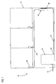
- the fiber optic network 10 is disposed in a facility 12 (e.g., individual residence, apartment complex, condominium, business, etc.).
- the fiber optic network 10 includes a feeder cable 14 that is in optical communication with a central office (not shown).
- the feeder cable 14 enters a distribution device 16 (e.g., a fiber distribution hub, a network interface device, etc.) that includes one or more optical splitters (e.g., 1-to-8 splitters, 1-to-16 splitters, 1-to-32 splitters, etc.).
- the optical splitters split the feeder cable 14 into a plurality of individual fibers.
- the distribution device 16 is disposed in the facility 12. In an alternate embodiment, the distribution device 16 is disposed outside the facility 12.
- the facility 12 includes a fiber optic enclosure 18.
- a fiber optic enclosure suitable for use in the facility 12 has been described in U.S. Patent No. 7,715,679 .
- the fiber optic enclosure 18 defines an interior region 20.
- a plurality of fiber optic adapters 22 is disposed in the interior region 20 of the fiber optic enclosure 18.
- the fiber optic adapters 22 are SC-type adapters. SC-type adapters have been described in U.S. Patent No. 5,317,663 .
- Each of the fiber optic adapters 22 includes a main body 24 having a first side 26 and an oppositely disposed second side 28. The first and second sides 26, 28 are adapted to receive connectorized ends of optical fibers.
- the plurality of fiber optic adapters 22 is disposed on a plurality of adapter modules 30 (shown schematically in FIG. 2 ).
- the plurality of adapter modules 30 is a plurality of sliding adapter modules. Sliding adapter modules have been described in U.S. Patent Nos. 5,497,444 , 5,717,810 , 6,491,051 and 7,416,349 .
- each adapter module 30 there are N number of adapter modules 30 disposed in the interior region 20 of the fiber optic enclosure 18 with each adapter module 30 including M number of fiber optic adapters 22.
- a distribution cable 32 extends between the distribution device 16 and the fiber optic enclosure 18.
- the distribution cable 32 may be disposed on a cable spool that is disposed on the fiber optic enclosure 18 prior to being routed to the distribution device 16.
- the distribution cable 32 includes multiple optical fibers.
- the distribution cable 32 includes a first end 34 and an oppositely disposed second end 36. The first end 34 enters the distribution device 16 and is in optical communication with the plurality of individual fibers from the optical splitters.
- the second end 36 of the distribution cable 32 enters the fiber optic enclosure 18.
- the second end 36 of the first cable 32 is connectorized.
- the connectorized ends of the optical fibers of the distribution cable 32 are engaged with the first sides 26 of the fiber optic adapters 22 disposed in the interior region 20 of the fiber optic enclosure 18.
- a fiber optic cable 40 (e.g., a subscriber cable) extends between the fiber optic enclosure 18 and an end location 42.
- a plurality of fiber optic cables 40 extends between the fiber optic enclosure 18 and a plurality of end locations 42.
- the fiber optic cable 40 includes an optical fiber 46, a buffer layer 48, a strength layer 50 and an outer jacket 52.
- the optical fiber 46 includes a core.
- the core is made of a glass material, such as a silica-based material, having a first index of refraction.
- the core has an outer diameter of less than or equal to about 10 ⁇ m.
- the core of the optical fiber 46 is surrounded by a cladding that is also made of a glass material, such as a silica based-material.
- the cladding defines a second index of refraction that is less than the first index of refraction defined by the core. This difference between the first index of refraction of the core and the second index of refraction of the cladding allows an optical signal that is transmitted through the optical fiber 46 to be confined to the core.
- the cladding has an outer diameter of less than or equal to about 125 ⁇ m.
- a coating surrounds the cladding.
- the coating includes an inner layer and an outer layer.
- the inner layer of the coating is immediately adjacent to the cladding such that the inner layer surrounds the cladding.
- the inner layer is a polymeric material (e.g., polyvinyl chloride, polyethylenes, polyurethanes, polypropylenes, polyvinylidene fluorides, ethylene vinyl acetate, nylon, polyester, or other materials) having a low modulus of elasticity.
- the low modulus of elasticity of the inner layer functions to protect the optical fiber 46 from microbending.
- the outer layer of the coating is a polymeric material having a higher modulus of elasticity than the inner layer.
- the outer layer of the coating is immediately adjacent to the inner layer such that the outer layer surrounds the inner layer.
- the higher modulus of elasticity of the outer layer functions to mechanically protect and retain the shape of optical fiber 46 during handling.
- the outer layer defines an outer diameter ⁇ 1 of less than or equal to about 250 ⁇ m.
- the outer diameter ⁇ 1 of the outer layer is in the range of about 242 ⁇ m to about 245 ⁇ m.
- the outer layer defines an outer diameter ⁇ 1 of less than or equal to about 200 ⁇ m.
- the optical fiber 46 is manufactured to reduce the sensitivity of the optical fiber 46 to micro or macro-bending (hereinafter referred to as "bend insensitive").
- Exemplary bend insensitive optical fibers 46 have been described in U.S. Patent Nos. 7,587,111 and 7,623,747 .
- An exemplary bend insensitive optical fiber 46 suitable for use in the fiber optic cable 40 of the present disclosure is commercially available from Draka Comteq under the name BendBright XS.
- the buffer layer 48 is depicted as a tight layer that surrounds the optical fiber 46. It will be understood, however, that the scope of the present disclosure is not limited to the buffer layer 48 being a tight layer.
- the buffer layer 48 can have any number of conventionally known constructions.
- the buffer layer 48 can be made of a polymeric material such as polyvinyl chloride (PVC).
- PVC polyvinyl chloride
- Other polymeric materials e.g., polyethylenes, polyurethanes, polypropylenes, polyvinylidene fluorides, ethylene vinyl acetate, nylon, polyester, or other materials
- the buffer layer 48 defines an outer diameter ⁇ 2 that is less than or equal to about 1 mm. In another embodiment, the outer diameter ⁇ 2 of the buffer layer 48 is less than or equal to about 900 ⁇ m.
- the strength layer 50 is adapted to inhibit axial tensile loading from being applied to the optical fiber 46.
- the first strength layer 50 extends the length of the fiber optic cable 40 and is disposed in a generally longitudinal direction along the fiber optic cable 40 between the buffer layer 48 and the outer jacket 52.
- the strength layer 50 can include yarns, fibers, threads, tapes, films, epoxies, filaments or other structures.
- the strength layer 50 includes a plurality of aramid yams (e.g., KEVLAR ® yarns).
- the outer jacket 52 surrounds the strength layer 50.
- the outer jacket 52 includes an outer diameter that is less than or equal to about 4 mm.
- the outer jacket 52 includes an outer diameter ⁇ 3 that is less than or equal to about 3 mm.
- the outer diameter ⁇ 3 of the outer jacket 52 is less than or equal to about 2 mm.
- the outer diameter ⁇ 3 of the outer jacket 52 is equal to about 1.65 mm.
- the outer jacket 52 includes a base material.
- the base material is a polymer material such as a flexible chain polymer (i.e., one in which successive units of the polymer chain are free to rotate with respect to one another, so that the polymer chain can assume a random shape).
- Example base materials include conventional thermoplastic polymers such as polyethylene, polypropylene, ethylene-propylene, copolymers, polystyrene, and styrene copolymers, polyvinyl chloride, polyamide (nylon), polyesters such as polyethylene terephthalate, polyetheretherketone, polyphenylene sulfide, polyetherimide, polybutylene terephthalate, low smoke zero halogens polyolefins and polycarbonate, as well as other thermoplastic materials. Additives may also be added to the material.
- Example additives include pigments, fillers, coupling agents, flame retardants, lubricants, plasticizers, ultraviolet stabilizers or other additives.
- the base material can also include combinations of the above materials as well as combinations of other materials.
- the outer jacket 52 has a structure adapted to resist post-extrusion shrinkage.
- the outer jacket 52 includes a plurality of discrete shrinkage-reduction members (e.g., rods, tendrils, extensions, fibers, etc.) embedded within the base material.
- Shrinkage-reduction members suitable for use with the fiber optic cable 40 have been described in U.S. Patent No. 7,379,642 .
- the shrinkage-reduction members preferably demonstrate less shrinkage than the base material when reheated.
- the shrinkage-reduction members are embedded in the base material, the shrinkage-reduction members provide reinforcement that resists shrinkage of the base material.
- the shrinkage-reduction material has a melting temperature that is greater than the melting temperature of the base material.
- the shrinkage-reduction members are preferably elongated and have lengths that are aligned generally parallel to a longitudinal axis of the fiber optic cable 40.
- Each of the shrinkage-reduction members preferably does not extend the entire length of the fiber optic cable 40. Instead, each of the shrinkage-reduction members preferably coincides with or extends along only a relatively short segment of the total length of the fiber optic cable 40.
- at least some of the shrinkage-reduction members have lengths in the range of .2 mm - 100 mm. In another embodiment, at least some of the shrinkage-reduction members have lengths in the range of 5 - 60 mm.
- the shrinkage-reduction members have lengths in the range of about 10 - 40 mm.
- a majority of the shrinkage-reduction members provided within the base material can be within the size ranges provided above, or within other size ranges.
- most of the shrinkage-reduction members are preferably discrete or separate from one another.
- many of the shrinkage-reduction members are preferably separated or isolated from one another by portions of the base material.
- the concentration of the shrink-reduction members is relatively small as compared to the base material.
- the shrink-reduction material constitutes less than 2% of the total weight of the outer jacket 52.
- the shrink-reduction material constitutes less than 1.5% of the total weight of the outer jacket 52.
- the shrink-reduction material constitutes less than or equal to 1.25% of the total weight of the outer jacket 52.
- the shrink-reduction material constitutes less than or equal to 1.0% of the total weight of the outer jacket 52. While preferred embodiments use less than 2% of the shrink-reduction material by weight, other embodiments within the scope of the present invention can use more than 2% by weight of the shrink-reduction material.
- the shrinkage-reduction members are made from a material that can be softened and reshaped in the extrusion process.
- the shrinkage-reduction members include liquid crystal polymers.
- Example liquid crystal polymers are described in U.S. Patent Nos. 3,991,014 ; 4,067,852 ; 4,083,829 ; 4,130,545 ; 4,161,470 ; 4,318,842 ; and 4,468,364 .
- Liquid crystal polymers are polymers that are anisotropic and highly oriented, even in a softened or liquid phase.
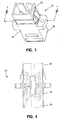
- each of the fiber optic cables 40 includes a first axial end 53 and an oppositely disposed second axial end 54.
- the first axial end 53 of the fiber optic cable 40 includes a connector 55.
- the connector 55 is adapted to be received in the second side 28 of one of the fiber optic adapters 22.
- the connector 55 disposed at the first axial end 53 of each of the fiber optic cables 40 is an SC-type connector.
- the connector 55 includes a first end 56 and an oppositely disposed second end 57.
- the first end 56 is adapted for insertion into the fiber optic adapter 22.
- the first end 56 includes a ferrule 58 in which the optical fiber 46 of the fiber optic cable 40 is mounted.
- the fiber optic cable 40 extends outwardly from the second end 57 of the connector 55.
- the second end 57 includes a strain relief boot 59.
- the strain relief boot 59 is adapted to protect the fiber optic cable 40 at the second end 57 of the connector from bending.
- the fiber optic cable bundle 60 includes a first end portion 61 a and an oppositely disposed second end portion 61b.
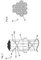
- the fiber optic cable bundle 60 includes a plurality of fiber optic cables 40.
- the total number (or total quantity) of fiber optic cables 40 in the fiber optic cable bundle 60 is equal to the total number (N ⁇ M) of fiber optic adapters 22 in the enclosure 18.
- the total number (or total quantity) of fiber optic cables 40 in the fiber optic cable bundle 60 is a portion of the total number of fiber optic adapters 22 in the enclosure 18.
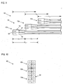
- the fiber optic cable bundle 60 includes twelve fiber optic cables 40. As shown in FIGS. 7 and 8 , three of the fiber optic cables 40 are disposed in the center of the fiber optic cable bundle 60 while the remaining nine fiber optic cables 40 are disposed about the three fiber optic cables 40 so the nine fiber optic cables 40 are disposed at the outside of the fiber optic cable bundle 60.
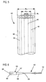
- the fiber optic cables 40 of the fiber optic cable bundle 60 are held together by a plurality of binder members 62.
- the plurality of binder members 62 is strands of aramid yarn.
- the plurality of binder members 62 is ribbonized fiberglass.
- the binder members 62 include a first set of binder members 62a and a second set of binder members 62b. In one embodiment, each of the first and second sets of binder members 62a, 62b includes one to ten binder members. In another embodiment, each of the first and second sets of binder members 62a, 62b includes one to eight binder members. In another embodiment, each of the first and second sets of binder members 62a, 62b includes four binder members.
- the first set of binder members 62a includes a first binder member 64 while the second set of binder members 62b includes a second binder member 66.
- the second binder member 66 is disposed over the first binder member 64 such that the first and second binder members 64, 66 are unbraided or nonwoven.
- the first and second binder members 64, 66 are contra-helically served.
- the first binder member 64 is disposed about the fiber optic cables 40 in a generally right-handed helical configuration while the second binder member 66 is disposed over the first binder member 64 in a generally left-handed helical configuration.
- the first and second binder members 64, 66 are disposed at angles ⁇ 1 , ⁇ 2 from a longitudinal line 68.
- the angles ⁇ 1 , ⁇ 2 are equal but opposite.
- the angles ⁇ 1 , ⁇ 2 are in the range of about 0.1 degrees to about 60 degrees.
- the angles ⁇ 1 , ⁇ 2 are in the range of about 5 degrees to about 45 degrees.
- the angles ⁇ 1 , ⁇ 2 are in the range of about 0.1 degrees to about 30 degrees.
- each of the binder members 62 has a lay length in a range of about 1 inch to about 18 inches.
- the lay length is the axial distance in which each of the binder members 62 wraps 360° around the fiber optic cable bundle 60.
- the fiber optic cables 40 in the fiber optic cable bundle 60 are disposed in a plurality of groups 70.
- the fiber optic cables 40 in the fiber optic cable bundle 60 are disposed in a first group 70a, a second group 70b and a third group 70c.
- the total number (or total quantity) of fiber optic cables 40 in each group 70 is equal to at least a portion of the total number of fiber optic adapters 22 per adapter module 30.
- each adapter module 30 includes four fiber optic adapters 22.
- each group 70 of fiber optic cables 40 in the fiber optic cable bundle 60 includes four fiber optic cables 40. Therefore, in the depicted embodiments, the total number (or total quantity) of fiber optic cables 40 in each group 70 is equal to the total number (or total quantity) of fiber optic adapters 22 in one of the adapter modules 30.
- the groups 70 of the fiber optic cable bundle 60 are axially staggered relative to one another.
- the connectors 55 of the first group 70a are axially offset from the connectors 55 of the second and third groups 70b, 70c at the first end portion 61a of the fiber optic cable bundle 60 so that the first group 70a extends axially outward from the second and third groups 70b, 70c.
- the first ends 56 of the connectors 55 of the first group 70a are axially offset from the first ends 56 of the connectors 55 of the second group 70b by a first axial offset distance D 1 at the first end portion 61a of the fiber optic cable bundle 60.
- first ends 56 of the connectors 55 of the second group 70b are axially adjacent to the second ends 57 of the connectors 55 of the first group 70a at the first end portion 61a of the fiber optic cable bundle 60.
- first ends 56 of the connectors 55 of the second group 70b are axially adjacent to the strain relief boots 59 of the second ends 57 of the connectors 55 of the first group 70a.
- the first axial offset distance D 1 is greater than or equal to about 1 inch. In another embodiment, the first axial offset distance D 1 is greater than or equal to about 1.5 inches. In another embodiment, the first axial offset distance D 1 is greater than or equal to about 2.0 inches.
- the first ends 56 of the connectors 55 of the first group 70a are axially offset from the first ends 56 of the connectors 55 of the third group 70c by a second axial offset distance D 2 at the first end portion 61 a of the fiber optic cable bundle 60.
- the second axial offset distance D 2 is greater than or equal to about 2 inches. In another embodiment, the second axial offset distance D 2 is greater than or equal to about 3 inches. In another embodiment, the second axial offset distance D 2 is greater than or equal to about 4 inches.
- the first axial offset distance D 1 is less than the second axial offset distance D 2 . In one embodiment, the first axial offset distance D 1 is about 50% of the second axial offset distance D 2 .
- the second group 70b is disposed in the fiber optic cable bundle 60 so that the connectors 55 of the second group 70b are axially between the connectors 55 of the first group 70a and the connectors 55 of the third group 70c.
- the connectors 55 of the second group 70b are axially offset from the connectors 55 of the third group 70c so that the second group 70b extends axially outward from the third group 70c at the first end portion 61 a of the fiber optic cable bundle 60.
- the first ends 56 of the connectors 55 of the second group 70b are axially offset from the first ends 56 of the connectors 55 of the third group 70c by a third axial offset distance D 3 at the first end portion 61 a of the fiber optic cable bundle 60.
- first ends 56 of the connectors 55 of the third group 70c are axially adjacent to the second ends 57 of the connectors 55 of the second group 70b. In the depicted embodiment, the first ends 56 of the connectors 55 of the third group 70c are axially adjacent to the strain relief boots 59 of the second ends 57 of the connectors 55 of the second group 70b.
- the third axial offset distance D 3 is greater than or equal to about 1 inch. In another embodiment, the third axial offset distance D 3 is greater than or equal to about 1.5 inches. In another embodiment, the third axial offset distance D 3 is greater than or equal to about 2.0 inches. In another embodiment, the third axial offset distance D 3 is equal to the first axial offset distance D 1 .
- the fiber optic cable bundle 60 is routed to the enclosure 18.
- the first group 70a of fiber optic cables 40 in the fiber optic cable bundle 60 is routed to fiber optic adapters 22 in a first adapter module 30a.
- the second group 70b of fiber optic cables 40 in the fiber optic cable bundle 60 is routed to fiber optic adapters 22 in a second adapter module 30b.
- the third group 70c of fiber optic cables 40 in the fiber optic cable bundle 60 is routed to fiber optic adapters 22 in a third adapter module 30c.
- the first adapter module 30a is disposed the farthest distance from an opening 80 in the enclosure 18 through which the fiber optic cable bundle 60 enters the enclosure out of the first, second and third adapter modules 30a, 30b, 30c.
- the third adapter module 30c is disposed closest to the opening 80 out of the first, second and third adapter modules 30a, 30b, 30c while the second adapter module 30b is disposed between the first and third adapter modules 30a, 30c.
- the first, second and third axial offset distances D 1 , D 2 , D 3 account for the spacing between the first, second and third adapter modules 30a, 30b, 30c.
- the spacing between the first and second adapter modules 30a, 30b is less than or equal to about the first axial offset distance D 1 .
- the spacing between the second and third adapter modules 30b, 30c is less than or equal to about the third axial offset distance D 3 .
- the spacing between the first and third adapter modules 30a, 30c is less than or equal to the second axial offset distance D 2 .
- the fiber optic cables 40 are disposed in the fiber optic cable bundle 60 so that a length L 1 of the first group 70a of fiber optic cables 40 of the fiber optic cable bundle 60 is greater than a length L 2 of the second group 70b and a length L 3 of the third group 70c.
- the length L 2 of the second group 70b of fiber optic cable 40 of the fiber optic cable bundle 60 is greater than the length L 3 .
- the first fiber optic cable bundle 160 includes fiber optic cables 40.
- the total number (or total quantity) of fiber optic cables 40 in the first fiber optic cable bundle 160 is equal to a portion of the total number (N ⁇ M) of fiber optic adapters 22 in the enclosure 18. In the depicted embodiment, the total number (or total quantity) of fiber optic cables 40 in the first fiber optic cable bundle 160 is equal to about 50% of the total number of fiber optic adapter 22 in the enclosure 18.
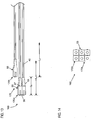
- the first fiber optic cable bundle 160 includes six fiber optic cables 40. As shown in FIGS. 11 and 12 , one of the fiber optic cables 40 is disposed in the center of the first fiber optic cable bundle 160 while the remaining five fiber optic cables 40 are disposed about the one fiber optic cable 40 so the five fiber optic cables 40 are disposed at the outside of the first fiber optic cable bundle 160.
- the fiber optic cables 40 of the first fiber optic cable bundle 160 are held together by the plurality of binder members 62.
- the fiber optic cables 40 of the first fiber optic cable bundle 160 are disposed in a plurality of groups 170.
- the fiber optic cables 40 in the first fiber optic cable bundle 160 are disposed in a first group 170a and a second group 170b.
- the total number (or total quantity) of fiber optic cables 40 in the first group 170a is equal to the total number (or total quantity) of fiber optic adapters 22 in one of the adapter modules 30 while the number of fiber optic cables 40 in the second group 170b is equal to a portion of the total number of fiber optic adapters 22 in one of the adapter modules 30.
- the total number (or total quantity) of fiber optic cables 40 in the second group 170b is equal to 50% of the total number of fiber optic adapters 22 in one of the adapter modules 30.
- the total number (or total quantity) of fiber optic cables 40 in the first group 170a is equal to four while the number of fiber optic cables 40 in the second group 170b is equal to two.
- the groups 170 of the first fiber optic cable bundle 160 are axially staggered relative to one another.
- the connectors 55 of the first group 170a are axially offset from the connectors 55 of the second group 170b so that the first group 170a extends axially outward from the second group 170b.
- the first ends 56 of the connectors 55 of the first group 170a are axially offset from the first ends 56 of the connectors 55 of the second group 170b by a fourth axial distance D 4 .
- first ends 56 of the connectors 55 of the second group 170b are axially adjacent to the second ends 57 of the connectors 55 of the first group 170a.
- first ends 56 of the connectors 55 of the second group 170b are axially adjacent to the strain relief boots 59 of the second ends 57 of the connectors 55 of the first group 170a.
- the fourth axial distance D 4 is greater than or equal to about 1 inch. In another embodiment, the fourth axial distance D 4 is greater than or equal to about 1.5 inches. In another embodiment, the fourth axial distance D 4 is greater than or equal to about 2.0 inches.
- the fiber optic cables 40 in the first group 170a of the first fiber optic cable bundle 160 have a length L 4 while the fiber optic cables 40 in the second group 170b of the first fiber optic cable bundle 160 have a length L 5 .
- the length L 4 of the first group 170a is greater than the length L 5 of the second group 170b.
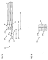
- the second fiber optic cable bundle 260 includes fiber optic cables 40.
- the total number (or total quantity) of fiber optic cables 40 in the second fiber optic cable bundle 260 is equal to a portion of the total number (N ⁇ M) of fiber optic adapters 22 in the enclosure 18.
- the total number (or total quantity) of fiber optic cables 40 in the second fiber optic cable bundle 160 is equal to about 50% of the total number of fiber optic adapter 22 in the enclosure 18.
- the fiber optic cables 40 of the second fiber optic cable bundle 260 are disposed in a plurality of groups 270.
- the fiber optic cables 40 in the second fiber optic cable bundle 260 are disposed in a first group 270a and a second group 270b.
- the total number (or total quantity) of fiber optic cables 40 in the first group 270a is equal to a portion of the total number of fiber optic adapters 22 in one of the adapter modules 30 while the total number (or total quantity) of fiber optic cables 40 in the second group 270b is equal to the total number of fiber optic adapters 22 in one of the adapter modules 30.
- the total number (or total quantity) of fiber optic cables 40 in the first group 270a is equal to 50% of the total number of fiber optic adapters 22 in one of the adapter modules 30.
- the total number (or total quantity) of fiber optic cables 40 in the first group 270a is equal to two while the total number (or total quantity) of fiber optic cables 40 in the second group 270b is equal to four.
- the groups 270 of the second fiber optic cable bundle 260 are axially staggered relative to one another.
- the connectors 55 of the first group 270a are axially offset from the connectors 55 of the second group 270b so that the first group 270a extends axially outward from the second group 270b.
- the first ends 56 of the connectors 55 of the first group 270a are axially offset from the first ends 56 of the connectors 55 of the second group 270b by a fifth axial distance D 5 .
- first ends 56 of the connectors 55 of the second group 270b are axially adjacent to the second ends 57 of the connectors 55 of the first group 270a.
- first ends 56 of the connectors 55 of the second group 270b are axially adjacent to the strain relief boots 59 of the second ends 57 of the connectors 55 of the first group 270a.
- the fifth axial distance D 5 is about equal to the fourth axial distance D 4 . In another embodiment, the fifth axial distance D 5 is greater than or equal to about 1 inch. In another embodiment, the fifth axial distance D 5 is greater than or equal to about 1.5 inches. In another embodiment, the fifth axial distance D 5 is greater than or equal to about 2.0 inches.
- the fiber optic cables 40 in the first group 270a of the second fiber optic cable bundle 260 have a length L 6 while the fiber optic cables 40 in the second group 270b of the second fiber optic cable bundle 260 have a length L 7 .
- the length L 6 of the first group 270a is greater than the length L 7 of the second group 270b.
- the length L 6 of the fiber optic cables 40 of the first group 270a of the second fiber optic cable bundle 260 is equal to the length L 5 of the fiber optic cables 40 of the second group 170b of the first fiber optic cable bundle 160.
- the first and second fiber optic cable bundles 160, 260 are adapted to be routed to the enclosure 18.
- the first group 170a of fiber optic cables 40 in the first fiber optic cable bundle 160 is routed to fiber optic adapters 22 in a first adapter module 30a.
- the second group 170b of fiber optic cables 40 in the first fiber optic cable bundle 160 is routed to fiber optic adapters 22 in a second adapter module 30b.
- the first group 270a of fiber optic cables 40 in the second fiber optic cable bundle 260 is routed to the remaining fiber optic adapters 22 in the second adapter module 30b while the second group 270b of fiber optic cables 40 in the second fiber optic cable bundle 260 is routed to fiber optic adapters 22 in a third adapter module 30c.
- the first group 270a of the second fiber optic cable bundle 260 and the second group 170b of the first fiber optic cable bundle 160 are routed to the same adapter module 30, the lengths of the first group 270a of the second fiber optic cable bundle 260 and the second group 170b of the first fiber optic cable bundle 160 can equal.
- the staggering of the groups 70, 170, 270 of fiber optic cables 40 in the fiber optic cable bundles 60, 160, 260 is potentially advantageous as it can allow for more fiber optic cables 40 to be disposed in the fiber optic cable bundle 60, 160, 260 and for that fiber optic cable bundle 60, 160, 260 to pass through a conduit.
- the total number (or total quantity) of fiber optic cables 40 in a group 70, 170, 270 is determined based on the inner diameter of the conduit and the size of the connectors 55.
- the cable spool assembly 300 includes a cable spool 302 and a cable spool stand 304.
- the cable spool 302 includes the fiber optic cable bundle 60 disposed about the cable spool 302.
- the fiber optic cable bundle 60 is coiled about a drum 305 of the cable spool 302 that is disposed between flanges 306 of the cable spool 302.
- the length of the fiber optic cable bundle 60 coiled about the drum 305 is less than or equal to about 500 feet.
- the cable spool 302 is rotatably engaged to the cable spool stand 304 so that the cable spool 302 can selectively rotate about an axis 308 (shown as a "+" in FIG. 14 ) of the cable spool stand 304 that extends through the center of the cable spool 302.
- the cable spool stand 304 is adapted to remain stationary as the cable spool 302 rotates about the axis 308.
- the cable spool stand 304 includes a base surface 310. With the base surface 310 disposed on the ground or other structure, the cable spool 302 can be rotated to deploy or pay out the fiber optic cable bundle 60.
- the connectors 55 of the fiber optic cables 40 of the fiber optic cable bundle 60 are disposed in a protective pulling eye 312.
- the pulling eye 312 is a flexible nylon mesh.
- the connectors 55 are disposed inside the nylon mesh 312.
- the nylon mesh 312 is then fixed to the fiber optic cable bundle 60 using an adhesive tape.
- an end 314 of the nylon mesh 312 includes a loop for pulling the nylon mesh 312 through the conduit.
Landscapes
- Physics & Mathematics (AREA)
- General Physics & Mathematics (AREA)
- Optics & Photonics (AREA)
- Light Guides In General And Applications Therefor (AREA)
- Optical Fibers, Optical Fiber Cores, And Optical Fiber Bundles (AREA)
Claims (12)
- Faseroptische Kabelbündelbaugruppe, umfassend:ein faseroptisches Kabelbündel (60) mit einem ersten Endteil und einem gegenüber angeordneten zweiten Endteil, wobei das faseroptische Kabelbündel (60) Folgendes umfasst:eine erste Gruppe (70a) von faseroptischen Kabeln, wobei jedes der faseroptischen Kabel in der ersten Gruppe ein erstes axiales Ende aufweist und einen Verbinder an dem ersten axialen Ende der faseroptischen Kabel in der ersten Gruppe umfasst;eine zweite Gruppe (70b) von faseroptischen Kabeln, wobei jedes der faseroptischen Kabel in der zweiten Gruppe ein erstes axiales Ende aufweist und einen Verbinder an dem ersten axialen Ende der faseroptischen Kabel in der zweiten Gruppe umfasst;wobei jedes der faseroptischen Kabel der ersten und zweiten Gruppe eine optische Faser, eine Verstärkungsschicht und einen die optische Faser und die Verstärkungsschicht umgebenden Mantel umfasst; undwobei die Verbinder der zweiten Gruppe (70b) um eine erste axiale Offsetdistanz (D1) an dem ersten Endteil des faseroptischen Kabelbündels von den Verbindern der ersten Gruppe (70a) versetzt sind; undmehrere Binderglieder (62), die gegen-helixförmig um das faseroptische Kabelbündel gelegt sind;dadurch gekennzeichnet, dass jedes der faseroptischen Kabel der ersten und zweiten Gruppe dafür ausgelegt ist, sich von dem ersten Endteil zu dem zweiten Endteil des faseroptischen Kabelbündels zu erstrecken, und wobei das faseroptische Kabelbündel einen mit den ersten axialen Enden der faseroptischen Kabel der ersten und zweiten Gruppe in Eingriff stehenden Ziehkopf umfasst.
- Faseroptische Kabelbündelbaugruppe nach Anspruch 1, wobei die erste axiale Offsetdistanz größer oder gleich 2 Zoll ist.
- Faseroptische Kabelbündelbaugruppe nach Anspruch 1, wobei die Gesamtmenge faseroptischer Kabel in dem faseroptischen Kabelbündel zwölf ist.
- Faseroptische Kabelbündelbaugruppe nach Anspruch 1, wobei eine Gesamtmenge faseroptischer Kabel in der ersten Gruppe gleich einer Gesamtmenge faseroptischer Kabel in der zweiten Gruppe ist.
- Faseroptische Kabelbündelbaugruppe nach Anspruch 4, wobei die Gesamtmenge faseroptischer Kabel in der ersten Gruppe gleich vier ist.
- Faseroptische Kabelbündelbaugruppe nach Anspruch 1, wobei eine Gesamtmenge faseroptischer Kabel in der zweiten Gruppe gleich der Hälfte einer Gesamtmenge der faseroptischen Kabel in der ersten Gruppe ist.
- Faseroptische Kabelbündelbaugruppe nach Anspruch 6, wobei die Gesamtmenge faseroptischer Kabel in der ersten Gruppe gleich vier ist.
- Faseroptische Kabelbündelbaugruppe nach Anspruch 1, die ferner eine dritte Gruppe von faseroptischen Kabeln umfasst, wobei jedes der faseroptischen Kabel in der dritten Gruppe ein erstes axiales Ende aufweist und einen Verbinder an dem ersten axialen Ende umfasst, wobei die Verbinder der dritten Gruppe um eine zweite axiale Offsetdistanz an dem ersten Endteil des faseroptischen Kabelbündels von den Verbindern der ersten Gruppe versetzt sind, wobei die zweite axiale Offsetdistanz größer als die erste axiale Offsetdistanz ist.
- Faseroptische Kabelbündelbaugruppe nach Anspruch 8, wobei die zweite axiale Offsetdistanz größer oder gleich 4 Zoll ist.
- Faseroptische Kabelbündelbaugruppe nach Anspruch 1, wobei jedes der Binderglieder aus Aramidgarn ist.
- Faseroptische Kabelbündelbaugruppe nach Anspruch 1, die ferner eine Kabelspule mit einem Trommelteil umfasst, wobei die faseroptische Kabelbündelbaugruppe um den Trommelteil der Kabelspule herum angeordnet ist.
- Faseroptische Kabelbündelbaugruppe nach Anspruch 1, wobei die faseroptische Kabelbündelbaugruppe eine dritte Gruppe von faseroptischen Kabeln umfasst, wobei jedes der faseroptischen Kabel in der dritten Gruppe ein erstes axiales Ende aufweist, wobei die ersten axialen Enden der dritten Gruppe um eine zweite axiale Offsetdistanz axial von den ersten axialen Enden der zweiten Gruppe versetzt sind.
Applications Claiming Priority (2)
| Application Number | Priority Date | Filing Date | Title |
|---|---|---|---|
| US30068910P | 2010-02-02 | 2010-02-02 | |
| PCT/US2011/023479 WO2011097299A2 (en) | 2010-02-02 | 2011-02-02 | Fiber optic cable bundle with staggered connectors |
Publications (4)
| Publication Number | Publication Date |
|---|---|
| EP2531877A2 EP2531877A2 (de) | 2012-12-12 |
| EP2531877A4 EP2531877A4 (de) | 2013-12-04 |
| EP2531877B1 true EP2531877B1 (de) | 2016-04-20 |
| EP2531877B9 EP2531877B9 (de) | 2016-07-13 |
Family
ID=44341733
Family Applications (1)
| Application Number | Title | Priority Date | Filing Date |
|---|---|---|---|
| EP11740299.0A Not-in-force EP2531877B9 (de) | 2010-02-02 | 2011-02-02 | Glasfaserkabelbündel mit versetzten verbindern |
Country Status (4)
| Country | Link |
|---|---|
| US (2) | US8801296B2 (de) |
| EP (1) | EP2531877B9 (de) |
| ES (1) | ES2583327T3 (de) |
| WO (1) | WO2011097299A2 (de) |
Families Citing this family (41)
| Publication number | Priority date | Publication date | Assignee | Title |
|---|---|---|---|---|
| US8500341B2 (en) * | 2009-11-20 | 2013-08-06 | Adc Telecommunications, Inc. | Fiber optic cable assembly |
| ES2583327T3 (es) * | 2010-02-02 | 2016-09-20 | Adc Telecommunications, Inc. | Mazo de cables de fibra óptica con conectores escalonados |
| US8805151B2 (en) | 2010-05-19 | 2014-08-12 | Adc Telecommunications, Inc. | Lashing together multiple fiber optic telecommunications cables |
| CN105068204B (zh) | 2011-10-07 | 2018-08-10 | Adc电信公司 | 带有缆线松弛管理的可滑动光纤连接模块 |
| US9170391B2 (en) | 2011-10-07 | 2015-10-27 | Adc Telecommunications, Inc. | Slidable fiber optic connection module with cable slack management |
| US9002166B2 (en) | 2011-10-07 | 2015-04-07 | Adc Telecommunications, Inc. | Slidable fiber optic connection module with cable slack management |
| US9075203B2 (en) | 2012-01-17 | 2015-07-07 | Adc Telecommunications, Inc. | Fiber optic adapter block |
| AU2013203864B2 (en) * | 2012-01-17 | 2014-10-23 | Commscope Technologies Llc | Fiber optic adapter block |
| US9195021B2 (en) | 2012-09-21 | 2015-11-24 | Adc Telecommunications, Inc. | Slidable fiber optic connection module with cable slack management |
| US10082636B2 (en) | 2012-09-21 | 2018-09-25 | Commscope Technologies Llc | Slidable fiber optic connection module with cable slack management |
| ES2953122T3 (es) | 2013-01-29 | 2023-11-08 | CommScope Connectivity Belgium BVBA | Sistema de distribución de fibra óptica |
| US9128262B2 (en) | 2013-02-05 | 2015-09-08 | Adc Telecommunications, Inc. | Slidable telecommunications tray with cable slack management |
| WO2014133943A1 (en) | 2013-02-27 | 2014-09-04 | Adc Telecommunications, Inc. | Slidable fiber optic connection module with cable slack management |
| HUE053625T2 (hu) | 2013-04-24 | 2021-07-28 | CommScope Connectivity Belgium BVBA | Optikai szálelosztási rendszer |
| AP2015008820A0 (en) | 2013-04-24 | 2015-10-31 | Adc Czech Republic Sro | Optical fiber distribution system |
| EP3230780B1 (de) | 2014-12-10 | 2023-10-25 | CommScope Technologies LLC | Verwaltungsmodul für faseroptische kabelüberlängen |
| DK3278159T3 (da) | 2015-04-03 | 2023-11-20 | CommScope Connectivity Belgium BVBA | Telekommunikationsfordelingselementer |
| EP3101459A1 (de) * | 2015-06-05 | 2016-12-07 | CCS Technology Inc. | Glasfaserkabelanordnungen und verfahren zur formung davon |
| MX2018006557A (es) * | 2015-11-30 | 2018-08-01 | Corning Optical Communications LLC | Ensamblado de haces de fibras para mantener un orden seleccionado en un cable de fibra optica. |
| ES2851948T3 (es) | 2016-04-19 | 2021-09-09 | Commscope Inc North Carolina | Bastidor de telecomunicaciones con bandejas deslizables |
| US11674345B2 (en) | 2016-04-19 | 2023-06-13 | Commscope, Inc. Of North Carolina | Door assembly for a telecommunications chassis with a combination hinge structure |
| US10501283B2 (en) * | 2016-06-22 | 2019-12-10 | The Boeing Company | Wire processing system |
| US10501284B2 (en) * | 2016-06-22 | 2019-12-10 | The Boeing Company | Wire processing system |
| US10310192B2 (en) | 2016-09-22 | 2019-06-04 | Commscope Technologies Llc | Fiber optic cable assembly |
| WO2018226959A1 (en) | 2017-06-07 | 2018-12-13 | Commscope Technologies Llc | Fiber optic adapter and cassette |
| WO2019079419A1 (en) | 2017-10-18 | 2019-04-25 | Commscope Technologies Llc | FIBER OPTIC CONNECTION CASSETTES |
| EP3759535A4 (de) | 2018-02-28 | 2021-11-10 | CommScope Technologies LLC | Gehäuseanordnung für telekommunikationsausrüstung |
| US11256054B2 (en) | 2018-04-16 | 2022-02-22 | Commscope Technologies Llc | Adapter structure |
| EP3781973A1 (de) | 2018-04-17 | 2021-02-24 | CommScope Connectivity Belgium BVBA | Telekommunikationsverteilungselemente |
| EP3844972B1 (de) | 2018-08-31 | 2022-08-03 | CommScope Connectivity Belgium BVBA | Rahmenanordnungen für glasfaserverteilungselemente |
| WO2020043911A1 (en) | 2018-08-31 | 2020-03-05 | CommScope Connectivity Belgium BVBA | Frame assemblies for optical fiber distribution elements |
| MX2021002249A (es) | 2018-08-31 | 2021-07-15 | CommScope Connectivity Belgium BVBA | Unidades de marco para elementos de distribucion de fibra optica. |
| EP3844547A1 (de) | 2018-08-31 | 2021-07-07 | CommScope Connectivity Belgium BVBA | Rahmenanordnungen für glasfaserverteilungselemente |
| EP3844973B1 (de) | 2018-08-31 | 2024-11-06 | CommScope Connectivity Belgium BVBA | Rahmenanordnungen für optische faserverteilungselemente |
| WO2020084012A1 (en) | 2018-10-23 | 2020-04-30 | CommScope Connectivity Belgium BVBA | Frame assemblies for optical fiber distribution elements |
| EP3914947B1 (de) | 2019-01-25 | 2025-10-22 | CommScope Connectivity Belgium BVBA | Rahmenanordnungen für optische faserverteilungselemente |
| US12174443B2 (en) | 2020-01-22 | 2024-12-24 | CommScope Connectivity Belgium BVBA | Cable termination units for optical fiber distribution elements |
| EP4094108B1 (de) | 2020-01-24 | 2025-06-18 | CommScope Connectivity Belgium BVBA | Telekommunikationsverteilungselemente |
| EP4100777A1 (de) | 2020-02-07 | 2022-12-14 | CommScope Connectivity Belgium BVBA | Telekommunikationsmodulanordnungen |
| WO2022094277A1 (en) * | 2020-10-30 | 2022-05-05 | Commscope Technologies Llc | Compact cable assembly |
| US11914209B2 (en) | 2022-02-28 | 2024-02-27 | Prysmian S.P.A. | Pre-terminated optical cable |
Citations (1)
| Publication number | Priority date | Publication date | Assignee | Title |
|---|---|---|---|---|
| DE102007024476A1 (de) * | 2007-05-25 | 2008-11-27 | Dirk Selbach | Kabelbaumherstellungssystem |
Family Cites Families (70)
| Publication number | Priority date | Publication date | Assignee | Title |
|---|---|---|---|---|
| US2767742A (en) | 1952-11-04 | 1956-10-23 | James W Channell | Method and means for lashing cable |
| US3991014A (en) | 1974-05-10 | 1976-11-09 | E. I. Du Pont De Nemours And Company | Polyesters of derivatives of hydroquinone and bis(carboxyphenyl)ether |
| US4083829A (en) | 1976-05-13 | 1978-04-11 | Celanese Corporation | Melt processable thermotropic wholly aromatic polyester |
| US4067852A (en) | 1976-05-13 | 1978-01-10 | Celanese Corporation | Melt processable thermotropic wholly aromatic polyester containing polybenzoyl units |
| US4130545A (en) | 1977-09-12 | 1978-12-19 | Celanese Corporation | Melt processable thermotropic wholly aromatic polyester comprising both para-oxybenzoyl and meta-oxybenzoyl moieties |
| US4161470A (en) | 1977-10-20 | 1979-07-17 | Celanese Corporation | Polyester of 6-hydroxy-2-naphthoic acid and para-hydroxy benzoic acid capable of readily undergoing melt processing |
| US4616470A (en) * | 1979-12-03 | 1986-10-14 | Konji Nakamura | Method of forming re-sealable dispenser-container |
| US4318842A (en) | 1980-10-06 | 1982-03-09 | Celanese Corporation | Polyester of 6-hydroxy-2-naphthoic acid, aromatic diol, and 1,4-cyclohexanedicarboxylic acid capable of undergoing melt processing |
| GB2093493B (en) | 1981-02-24 | 1984-12-12 | Pirelli Cavi Spa | Making core element for an optical fibre cable |
| JPS59195617A (ja) * | 1983-04-21 | 1984-11-06 | Mitsubishi Electric Corp | スタ−カプラ |
| US4468364A (en) | 1983-04-28 | 1984-08-28 | Celanese Corporation | Process for extruding thermotropic liquid crystalline polymers |
| JPS60177312A (ja) | 1984-02-24 | 1985-09-11 | Dainichi Nippon Cables Ltd | 光フアイバケ−ブルの製造方法 |
| JPS61230103A (ja) | 1985-04-03 | 1986-10-14 | Electric Power Dev Co Ltd | 架空線への光ケ−ブルの巻付方法 |
| IT1185951B (it) | 1985-09-27 | 1987-11-18 | Pirelli Cavi Spa | Procedimento e linea per la produzione di cavi |
| US4763983A (en) | 1986-12-31 | 1988-08-16 | Sumitomo Electric Research Triangle, Inc. | Optical transmission cable with messenger |
| US4832442A (en) | 1987-07-17 | 1989-05-23 | United Ropeworks (U.S.A.) Inc. | Method and apparatus for aerial installation of fiber optic cables |
| US5209416A (en) | 1988-10-28 | 1993-05-11 | Hughes Aircraft Company | High density filament winding and method for producing improved crossovers and inside payout |
| JP3001117B2 (ja) | 1990-05-28 | 2000-01-24 | 日本電信電話株式会社 | 光ケーブルとその製造方法 |
| JP3176390B2 (ja) | 1990-06-13 | 2001-06-18 | 宇部日東化成株式会社 | 強化プラスチック製鎧装ケーブルの製造方法 |
| US5421501A (en) | 1991-01-16 | 1995-06-06 | Haines; Roger C. | Method and apparatus for cable dispensing and placement |
| US6612516B1 (en) | 1991-01-16 | 2003-09-02 | H. Norman Clarkson | Method and apparatus for cable dispensing and placement |
| DE9107437U1 (de) * | 1991-06-17 | 1991-08-22 | Erhardt + Leimer GmbH, 86157 Augsburg | Vorrichtung zum Führen einer querstabilen Bahn |
| US5268971A (en) * | 1991-11-07 | 1993-12-07 | Alcatel Na Cable Systems, Inc. | Optical fiber/metallic conductor composite cable |
| US5345525A (en) | 1992-01-28 | 1994-09-06 | At&T Bell Laboratories | Utility optical fiber cable |
| US5390273A (en) | 1992-04-02 | 1995-02-14 | Pirelli Cable Corporation | Flame resistant optical fiber cable with optical fibers loosely enclosed in tubes |
| US5345526A (en) | 1993-02-11 | 1994-09-06 | Comm/Scope | Fiber optic cable having buffer tubes with optical fiber bundles therein and method for making same |
| KR970008188B1 (ko) * | 1993-04-08 | 1997-05-21 | 가부시끼가이샤 히다찌세이사꾸쇼 | 플래시메모리의 제어방법 및 그것을 사용한 정보처리장치 |
| US5317663A (en) | 1993-05-20 | 1994-05-31 | Adc Telecommunications, Inc. | One-piece SC adapter |
| TW232757B (en) | 1994-01-21 | 1994-10-21 | Adc Telecommunications Inc | High-density fiber distribution frame |
| US5448670A (en) | 1994-06-10 | 1995-09-05 | Commscope, Inc. | Elliptical aerial self-supporting fiber optic cable and associated apparatus and methods |
| JP3278539B2 (ja) * | 1995-01-25 | 2002-04-30 | 住友電気工業株式会社 | コネクタ付き光ケーブルの接続部余長処理方法および余長処理構造 |
| US5863083A (en) | 1996-11-20 | 1999-01-26 | Siecor Corporation | Pulling grip for pre-connectorized fiber optic cable |
| US5905834A (en) | 1997-07-21 | 1999-05-18 | Pirelli Cable Corporation | Combination loose tube optical fiber cable with reverse oscillating lay |
| JP3469118B2 (ja) | 1999-02-09 | 2003-11-25 | シーキューブ株式会社 | 空中架線方法およびこれに使用する架線誘導具 |
| US6760531B1 (en) * | 1999-03-01 | 2004-07-06 | Adc Telecommunications, Inc. | Optical fiber distribution frame with outside plant enclosure |
| US20030063868A1 (en) * | 2000-02-17 | 2003-04-03 | Vernon Fentress | Fiber optic cable termination devices and methods |
| US6557249B1 (en) | 2000-04-22 | 2003-05-06 | Halliburton Energy Services, Inc. | Optical fiber deployment system and cable |
| US7090406B2 (en) | 2000-05-26 | 2006-08-15 | Corning Cable Systems Llc | Preconnectorized fiber optic drop cables and assemblies |
| JP2002095121A (ja) | 2000-09-08 | 2002-03-29 | C I Kasei Co Ltd | 光ファイバーケーブルの布設方法 |
| US7016349B1 (en) * | 2000-09-29 | 2006-03-21 | Cypress Semiconductor Corp. | Logic for generating multicast/unicast address (es) |
| US6491051B2 (en) | 2000-12-29 | 2002-12-10 | Richard Carter Pierce | Solar survival shelter |
| US6556754B2 (en) * | 2001-08-10 | 2003-04-29 | 3M Innovative Properties Company | Three dimensional optical circuit |
| US6775445B2 (en) | 2002-01-11 | 2004-08-10 | Fujikura Ltd. | Optical fiber drop cable |
| US6805333B2 (en) | 2002-04-04 | 2004-10-19 | General Machine Products Co., Inc. | Cable lasher |
| US6766095B1 (en) * | 2002-09-18 | 2004-07-20 | Bellsouth Intellectual Property Corporation | Apparatus and method for slack management of fiber optic cables |
| WO2004042446A1 (en) | 2002-11-06 | 2004-05-21 | Sumitomo Electric Industries, Ltd. | Optical fiber ribbon and optical fiber cable using the same |
| US6915058B2 (en) * | 2003-02-28 | 2005-07-05 | Corning Cable Systems Llc | Retractable optical fiber assembly |
| US7421169B2 (en) | 2003-06-20 | 2008-09-02 | Fujikura Ltd. | Optical fiber cable |
| JP4041815B2 (ja) | 2003-11-11 | 2008-02-06 | 西日本電信電話株式会社 | ケーブルの螺旋状支持具 |
| US7006739B2 (en) | 2003-12-15 | 2006-02-28 | Corning Cable Systems Llc | Pre-connectorized fiber optic distribution cable |
| US7188415B2 (en) * | 2004-04-29 | 2007-03-13 | Carlyle, Inc. | Cable harness breakout assembly method |
| US7197214B2 (en) * | 2004-05-24 | 2007-03-27 | Corning Cable Systems Llc | Methods and apparatus for facilitating cable locating |
| US7330621B2 (en) * | 2004-05-24 | 2008-02-12 | Corning Cable Systems Llc | Flexible optical closure and other flexible optical assemblies |
| US7136555B2 (en) | 2004-05-27 | 2006-11-14 | Corning Cable Systems Llc | Distribution cable having articulated optical connection nodes |
| US7379642B2 (en) | 2005-01-18 | 2008-05-27 | Adc Telecommunications, Inc. | Low shrink telecommunications cable and methods for manufacturing the same |
| US7373069B2 (en) * | 2005-07-15 | 2008-05-13 | Daniel Otoniel Lazo | Fiber optic tester |
| US7416349B2 (en) | 2005-07-27 | 2008-08-26 | Adc Telecommunications, Inc. | Fiber optic adapter module |
| US7590320B2 (en) * | 2005-08-12 | 2009-09-15 | Afl Telecommunications Llc | Tapered cable for use in fiber to the premises applications |
| US7352947B2 (en) * | 2005-11-04 | 2008-04-01 | Leviton Manufacturing Co., Inc. | Cable management support system |
| US7418177B2 (en) | 2005-11-10 | 2008-08-26 | Adc Telecommunications, Inc. | Fiber optic cable breakout system, packaging arrangement, and method of installation |
| FR2893149B1 (fr) | 2005-11-10 | 2008-01-11 | Draka Comteq France | Fibre optique monomode. |
| FR2899693B1 (fr) | 2006-04-10 | 2008-08-22 | Draka Comteq France | Fibre optique monomode. |
| US7715679B2 (en) | 2007-05-07 | 2010-05-11 | Adc Telecommunications, Inc. | Fiber optic enclosure with external cable spool |
| US8422843B2 (en) | 2008-03-28 | 2013-04-16 | Adc Telecommunications, Inc. | Multi-fiber fiber optic cable |
| EP2285546A4 (de) | 2008-05-27 | 2014-03-12 | Adc Telecommunications Inc | Flexibles system zur formung extrudierter kabel sowie system, verfahren und werkzeuge dafür |
| US8254740B2 (en) | 2008-06-19 | 2012-08-28 | Adc Telecommunications, Inc. | Methods and systems for distributing fiber optic telecommunications services to local area |
| US7903925B2 (en) * | 2008-08-29 | 2011-03-08 | Corning Cable Systems Llc | Fiber optic furcation assembly having feature(s) for cable management |
| CA2739081C (en) * | 2008-10-09 | 2017-12-12 | Corning Cable Systems Llc | Fibre optic cable subunit assemblies |
| ES2583327T3 (es) * | 2010-02-02 | 2016-09-20 | Adc Telecommunications, Inc. | Mazo de cables de fibra óptica con conectores escalonados |
| US8805151B2 (en) | 2010-05-19 | 2014-08-12 | Adc Telecommunications, Inc. | Lashing together multiple fiber optic telecommunications cables |
-
2011
- 2011-02-02 ES ES11740299.0T patent/ES2583327T3/es active Active
- 2011-02-02 WO PCT/US2011/023479 patent/WO2011097299A2/en not_active Ceased
- 2011-02-02 EP EP11740299.0A patent/EP2531877B9/de not_active Not-in-force
- 2011-02-02 US US13/019,735 patent/US8801296B2/en active Active
-
2014
- 2014-08-11 US US14/456,667 patent/US20140348475A1/en not_active Abandoned
Patent Citations (1)
| Publication number | Priority date | Publication date | Assignee | Title |
|---|---|---|---|---|
| DE102007024476A1 (de) * | 2007-05-25 | 2008-11-27 | Dirk Selbach | Kabelbaumherstellungssystem |
Also Published As
| Publication number | Publication date |
|---|---|
| US8801296B2 (en) | 2014-08-12 |
| EP2531877A2 (de) | 2012-12-12 |
| EP2531877A4 (de) | 2013-12-04 |
| US20140348475A1 (en) | 2014-11-27 |
| WO2011097299A2 (en) | 2011-08-11 |
| EP2531877B9 (de) | 2016-07-13 |
| ES2583327T3 (es) | 2016-09-20 |
| US20110188809A1 (en) | 2011-08-04 |
| WO2011097299A3 (en) | 2011-12-29 |
Similar Documents
| Publication | Publication Date | Title |
|---|---|---|
| EP2531877B9 (de) | Glasfaserkabelbündel mit versetzten verbindern | |
| CA2610858C (en) | Fiber optic cables and methods for forming same | |
| US8224141B2 (en) | Multi-jacketed fiber optic cable | |
| AU2010321863B2 (en) | Fiber optic cable | |
| AU2014207795B2 (en) | Fiber optic ribbon cable | |
| EP3158378B1 (de) | Glasfaserkabel | |
| US20150309274A1 (en) | Fiber optic ribbon cable | |
| AU2020256042B2 (en) | Optical fiber cable with parallel ribbon subunits | |
| EP3120177A1 (de) | Glasfaserkabel mit glasfasern mit grossem durchmesser | |
| WO2025059529A1 (en) | Ruggedized microcable for inside plant applications | |
| US8870473B2 (en) | Method of terminating a fiber optic cable | |
| HK1124396B (en) | Fiber optic cables and methods for forming the same |
Legal Events
| Date | Code | Title | Description |
|---|---|---|---|
| PUAI | Public reference made under article 153(3) epc to a published international application that has entered the european phase |
Free format text: ORIGINAL CODE: 0009012 |
|
| 17P | Request for examination filed |
Effective date: 20120730 |
|
| AK | Designated contracting states |
Kind code of ref document: A2 Designated state(s): AL AT BE BG CH CY CZ DE DK EE ES FI FR GB GR HR HU IE IS IT LI LT LU LV MC MK MT NL NO PL PT RO RS SE SI SK SM TR |
|
| DAX | Request for extension of the european patent (deleted) | ||
| A4 | Supplementary search report drawn up and despatched |
Effective date: 20131106 |
|
| RIC1 | Information provided on ipc code assigned before grant |
Ipc: G02B 6/38 20060101AFI20131030BHEP Ipc: G02B 6/44 20060101ALI20131030BHEP |
|
| 17Q | First examination report despatched |
Effective date: 20150312 |
|
| GRAP | Despatch of communication of intention to grant a patent |
Free format text: ORIGINAL CODE: EPIDOSNIGR1 |
|
| INTG | Intention to grant announced |
Effective date: 20150929 |
|
| RAP1 | Party data changed (applicant data changed or rights of an application transferred) |
Owner name: ADC TELECOMMUNICATIONS, INC. |
|
| GRAS | Grant fee paid |
Free format text: ORIGINAL CODE: EPIDOSNIGR3 |
|
| GRAA | (expected) grant |
Free format text: ORIGINAL CODE: 0009210 |
|
| AK | Designated contracting states |
Kind code of ref document: B1 Designated state(s): AL AT BE BG CH CY CZ DE DK EE ES FI FR GB GR HR HU IE IS IT LI LT LU LV MC MK MT NL NO PL PT RO RS SE SI SK SM TR |
|
| REG | Reference to a national code |
Ref country code: GB Ref legal event code: FG4D |
|
| REG | Reference to a national code |
Ref country code: CH Ref legal event code: EP |
|
| REG | Reference to a national code |
Ref country code: AT Ref legal event code: REF Ref document number: 793048 Country of ref document: AT Kind code of ref document: T Effective date: 20160515 |
|
| REG | Reference to a national code |
Ref country code: IE Ref legal event code: FG4D |
|
| REG | Reference to a national code |
Ref country code: DE Ref legal event code: R096 Ref document number: 602011025614 Country of ref document: DE |
|
| REG | Reference to a national code |
Ref country code: LT Ref legal event code: MG4D |
|
| REG | Reference to a national code |
Ref country code: AT Ref legal event code: MK05 Ref document number: 793048 Country of ref document: AT Kind code of ref document: T Effective date: 20160420 |
|
| REG | Reference to a national code |
Ref country code: ES Ref legal event code: FG2A Ref document number: 2583327 Country of ref document: ES Kind code of ref document: T3 Effective date: 20160920 |
|
| REG | Reference to a national code |
Ref country code: NL Ref legal event code: MP Effective date: 20160420 |
|
| PG25 | Lapsed in a contracting state [announced via postgrant information from national office to epo] |
Ref country code: NL Free format text: LAPSE BECAUSE OF FAILURE TO SUBMIT A TRANSLATION OF THE DESCRIPTION OR TO PAY THE FEE WITHIN THE PRESCRIBED TIME-LIMIT Effective date: 20160420 Ref country code: PL Free format text: LAPSE BECAUSE OF FAILURE TO SUBMIT A TRANSLATION OF THE DESCRIPTION OR TO PAY THE FEE WITHIN THE PRESCRIBED TIME-LIMIT Effective date: 20160420 Ref country code: LT Free format text: LAPSE BECAUSE OF FAILURE TO SUBMIT A TRANSLATION OF THE DESCRIPTION OR TO PAY THE FEE WITHIN THE PRESCRIBED TIME-LIMIT Effective date: 20160420 Ref country code: NO Free format text: LAPSE BECAUSE OF FAILURE TO SUBMIT A TRANSLATION OF THE DESCRIPTION OR TO PAY THE FEE WITHIN THE PRESCRIBED TIME-LIMIT Effective date: 20160720 Ref country code: FI Free format text: LAPSE BECAUSE OF FAILURE TO SUBMIT A TRANSLATION OF THE DESCRIPTION OR TO PAY THE FEE WITHIN THE PRESCRIBED TIME-LIMIT Effective date: 20160420 |
|
| PG25 | Lapsed in a contracting state [announced via postgrant information from national office to epo] |
Ref country code: SE Free format text: LAPSE BECAUSE OF FAILURE TO SUBMIT A TRANSLATION OF THE DESCRIPTION OR TO PAY THE FEE WITHIN THE PRESCRIBED TIME-LIMIT Effective date: 20160420 Ref country code: PT Free format text: LAPSE BECAUSE OF FAILURE TO SUBMIT A TRANSLATION OF THE DESCRIPTION OR TO PAY THE FEE WITHIN THE PRESCRIBED TIME-LIMIT Effective date: 20160822 Ref country code: LV Free format text: LAPSE BECAUSE OF FAILURE TO SUBMIT A TRANSLATION OF THE DESCRIPTION OR TO PAY THE FEE WITHIN THE PRESCRIBED TIME-LIMIT Effective date: 20160420 Ref country code: GR Free format text: LAPSE BECAUSE OF FAILURE TO SUBMIT A TRANSLATION OF THE DESCRIPTION OR TO PAY THE FEE WITHIN THE PRESCRIBED TIME-LIMIT Effective date: 20160721 Ref country code: HR Free format text: LAPSE BECAUSE OF FAILURE TO SUBMIT A TRANSLATION OF THE DESCRIPTION OR TO PAY THE FEE WITHIN THE PRESCRIBED TIME-LIMIT Effective date: 20160420 Ref country code: AT Free format text: LAPSE BECAUSE OF FAILURE TO SUBMIT A TRANSLATION OF THE DESCRIPTION OR TO PAY THE FEE WITHIN THE PRESCRIBED TIME-LIMIT Effective date: 20160420 Ref country code: RS Free format text: LAPSE BECAUSE OF FAILURE TO SUBMIT A TRANSLATION OF THE DESCRIPTION OR TO PAY THE FEE WITHIN THE PRESCRIBED TIME-LIMIT Effective date: 20160420 |
|
| PG25 | Lapsed in a contracting state [announced via postgrant information from national office to epo] |
Ref country code: BE Free format text: LAPSE BECAUSE OF FAILURE TO SUBMIT A TRANSLATION OF THE DESCRIPTION OR TO PAY THE FEE WITHIN THE PRESCRIBED TIME-LIMIT Effective date: 20160420 |
|
| REG | Reference to a national code |
Ref country code: DE Ref legal event code: R097 Ref document number: 602011025614 Country of ref document: DE |
|
| PG25 | Lapsed in a contracting state [announced via postgrant information from national office to epo] |
Ref country code: RO Free format text: LAPSE BECAUSE OF FAILURE TO SUBMIT A TRANSLATION OF THE DESCRIPTION OR TO PAY THE FEE WITHIN THE PRESCRIBED TIME-LIMIT Effective date: 20160420 Ref country code: CZ Free format text: LAPSE BECAUSE OF FAILURE TO SUBMIT A TRANSLATION OF THE DESCRIPTION OR TO PAY THE FEE WITHIN THE PRESCRIBED TIME-LIMIT Effective date: 20160420 Ref country code: EE Free format text: LAPSE BECAUSE OF FAILURE TO SUBMIT A TRANSLATION OF THE DESCRIPTION OR TO PAY THE FEE WITHIN THE PRESCRIBED TIME-LIMIT Effective date: 20160420 Ref country code: SK Free format text: LAPSE BECAUSE OF FAILURE TO SUBMIT A TRANSLATION OF THE DESCRIPTION OR TO PAY THE FEE WITHIN THE PRESCRIBED TIME-LIMIT Effective date: 20160420 Ref country code: DK Free format text: LAPSE BECAUSE OF FAILURE TO SUBMIT A TRANSLATION OF THE DESCRIPTION OR TO PAY THE FEE WITHIN THE PRESCRIBED TIME-LIMIT Effective date: 20160420 |
|
| REG | Reference to a national code |
Ref country code: FR Ref legal event code: PLFP Year of fee payment: 7 |
|
| PLBE | No opposition filed within time limit |
Free format text: ORIGINAL CODE: 0009261 |
|
| STAA | Information on the status of an ep patent application or granted ep patent |
Free format text: STATUS: NO OPPOSITION FILED WITHIN TIME LIMIT |
|
| PG25 | Lapsed in a contracting state [announced via postgrant information from national office to epo] |
Ref country code: SM Free format text: LAPSE BECAUSE OF FAILURE TO SUBMIT A TRANSLATION OF THE DESCRIPTION OR TO PAY THE FEE WITHIN THE PRESCRIBED TIME-LIMIT Effective date: 20160420 |
|
| 26N | No opposition filed |
Effective date: 20170123 |
|
| PG25 | Lapsed in a contracting state [announced via postgrant information from national office to epo] |
Ref country code: SI Free format text: LAPSE BECAUSE OF FAILURE TO SUBMIT A TRANSLATION OF THE DESCRIPTION OR TO PAY THE FEE WITHIN THE PRESCRIBED TIME-LIMIT Effective date: 20160420 |
|
| PG25 | Lapsed in a contracting state [announced via postgrant information from national office to epo] |
Ref country code: MC Free format text: LAPSE BECAUSE OF FAILURE TO SUBMIT A TRANSLATION OF THE DESCRIPTION OR TO PAY THE FEE WITHIN THE PRESCRIBED TIME-LIMIT Effective date: 20160420 |
|
| REG | Reference to a national code |
Ref country code: CH Ref legal event code: PL |
|
| PG25 | Lapsed in a contracting state [announced via postgrant information from national office to epo] |
Ref country code: LI Free format text: LAPSE BECAUSE OF NON-PAYMENT OF DUE FEES Effective date: 20170228 Ref country code: CH Free format text: LAPSE BECAUSE OF NON-PAYMENT OF DUE FEES Effective date: 20170228 |
|
| REG | Reference to a national code |
Ref country code: IE Ref legal event code: MM4A |
|
| PG25 | Lapsed in a contracting state [announced via postgrant information from national office to epo] |
Ref country code: LU Free format text: LAPSE BECAUSE OF NON-PAYMENT OF DUE FEES Effective date: 20170202 |
|
| REG | Reference to a national code |
Ref country code: FR Ref legal event code: PLFP Year of fee payment: 8 |
|
| PG25 | Lapsed in a contracting state [announced via postgrant information from national office to epo] |
Ref country code: IE Free format text: LAPSE BECAUSE OF NON-PAYMENT OF DUE FEES Effective date: 20170202 |
|
| PG25 | Lapsed in a contracting state [announced via postgrant information from national office to epo] |
Ref country code: MT Free format text: LAPSE BECAUSE OF NON-PAYMENT OF DUE FEES Effective date: 20170202 |
|
| PG25 | Lapsed in a contracting state [announced via postgrant information from national office to epo] |
Ref country code: AL Free format text: LAPSE BECAUSE OF FAILURE TO SUBMIT A TRANSLATION OF THE DESCRIPTION OR TO PAY THE FEE WITHIN THE PRESCRIBED TIME-LIMIT Effective date: 20160420 |
|
| PGFP | Annual fee paid to national office [announced via postgrant information from national office to epo] |
Ref country code: DE Payment date: 20190227 Year of fee payment: 9 Ref country code: ES Payment date: 20190301 Year of fee payment: 9 Ref country code: IT Payment date: 20190222 Year of fee payment: 9 Ref country code: GB Payment date: 20190227 Year of fee payment: 9 |
|
| PGFP | Annual fee paid to national office [announced via postgrant information from national office to epo] |
Ref country code: FR Payment date: 20190225 Year of fee payment: 9 |
|
| PG25 | Lapsed in a contracting state [announced via postgrant information from national office to epo] |
Ref country code: HU Free format text: LAPSE BECAUSE OF FAILURE TO SUBMIT A TRANSLATION OF THE DESCRIPTION OR TO PAY THE FEE WITHIN THE PRESCRIBED TIME-LIMIT; INVALID AB INITIO Effective date: 20110202 |
|
| PG25 | Lapsed in a contracting state [announced via postgrant information from national office to epo] |
Ref country code: BG Free format text: LAPSE BECAUSE OF FAILURE TO SUBMIT A TRANSLATION OF THE DESCRIPTION OR TO PAY THE FEE WITHIN THE PRESCRIBED TIME-LIMIT Effective date: 20160420 |
|
| PG25 | Lapsed in a contracting state [announced via postgrant information from national office to epo] |
Ref country code: CY Free format text: LAPSE BECAUSE OF NON-PAYMENT OF DUE FEES Effective date: 20160420 |
|
| PG25 | Lapsed in a contracting state [announced via postgrant information from national office to epo] |
Ref country code: MK Free format text: LAPSE BECAUSE OF FAILURE TO SUBMIT A TRANSLATION OF THE DESCRIPTION OR TO PAY THE FEE WITHIN THE PRESCRIBED TIME-LIMIT Effective date: 20160420 |
|
| PG25 | Lapsed in a contracting state [announced via postgrant information from national office to epo] |
Ref country code: TR Free format text: LAPSE BECAUSE OF FAILURE TO SUBMIT A TRANSLATION OF THE DESCRIPTION OR TO PAY THE FEE WITHIN THE PRESCRIBED TIME-LIMIT Effective date: 20160420 |
|
| PG25 | Lapsed in a contracting state [announced via postgrant information from national office to epo] |
Ref country code: IS Free format text: LAPSE BECAUSE OF FAILURE TO SUBMIT A TRANSLATION OF THE DESCRIPTION OR TO PAY THE FEE WITHIN THE PRESCRIBED TIME-LIMIT Effective date: 20160820 |
|
| REG | Reference to a national code |
Ref country code: DE Ref legal event code: R119 Ref document number: 602011025614 Country of ref document: DE |
|
| GBPC | Gb: european patent ceased through non-payment of renewal fee |
Effective date: 20200202 |
|
| PG25 | Lapsed in a contracting state [announced via postgrant information from national office to epo] |
Ref country code: GB Free format text: LAPSE BECAUSE OF NON-PAYMENT OF DUE FEES Effective date: 20200202 Ref country code: DE Free format text: LAPSE BECAUSE OF NON-PAYMENT OF DUE FEES Effective date: 20200901 Ref country code: FR Free format text: LAPSE BECAUSE OF NON-PAYMENT OF DUE FEES Effective date: 20200229 |
|
| PG25 | Lapsed in a contracting state [announced via postgrant information from national office to epo] |
Ref country code: ES Free format text: LAPSE BECAUSE OF NON-PAYMENT OF DUE FEES Effective date: 20200203 |
|
| PG25 | Lapsed in a contracting state [announced via postgrant information from national office to epo] |
Ref country code: IT Free format text: LAPSE BECAUSE OF NON-PAYMENT OF DUE FEES Effective date: 20200202 |
|
| P01 | Opt-out of the competence of the unified patent court (upc) registered |
Effective date: 20230526 |