EP2531832B1 - Particle processing systems and methods for normalization/calibration of same - Google Patents
Particle processing systems and methods for normalization/calibration of same Download PDFInfo
- Publication number
- EP2531832B1 EP2531832B1 EP11707946.7A EP11707946A EP2531832B1 EP 2531832 B1 EP2531832 B1 EP 2531832B1 EP 11707946 A EP11707946 A EP 11707946A EP 2531832 B1 EP2531832 B1 EP 2531832B1
- Authority
- EP
- European Patent Office
- Prior art keywords
- particle
- output
- characteristic
- processing
- different
- Prior art date
- Legal status (The legal status is an assumption and is not a legal conclusion. Google has not performed a legal analysis and makes no representation as to the accuracy of the status listed.)
- Active
Links
Images


Classifications
-
- G—PHYSICS
- G01—MEASURING; TESTING
- G01N—INVESTIGATING OR ANALYSING MATERIALS BY DETERMINING THEIR CHEMICAL OR PHYSICAL PROPERTIES
- G01N15/00—Investigating characteristics of particles; Investigating permeability, pore-volume or surface-area of porous materials
- G01N15/10—Investigating individual particles
- G01N15/14—Optical investigation techniques, e.g. flow cytometry
- G01N15/1484—Optical investigation techniques, e.g. flow cytometry microstructural devices
-
- G—PHYSICS
- G01—MEASURING; TESTING
- G01N—INVESTIGATING OR ANALYSING MATERIALS BY DETERMINING THEIR CHEMICAL OR PHYSICAL PROPERTIES
- G01N15/00—Investigating characteristics of particles; Investigating permeability, pore-volume or surface-area of porous materials
- G01N15/10—Investigating individual particles
- G01N15/1012—Calibrating particle analysers; References therefor
-
- G—PHYSICS
- G01—MEASURING; TESTING
- G01N—INVESTIGATING OR ANALYSING MATERIALS BY DETERMINING THEIR CHEMICAL OR PHYSICAL PROPERTIES
- G01N15/00—Investigating characteristics of particles; Investigating permeability, pore-volume or surface-area of porous materials
- G01N15/10—Investigating individual particles
- G01N15/14—Optical investigation techniques, e.g. flow cytometry
- G01N15/1429—Signal processing
-
- G—PHYSICS
- G01—MEASURING; TESTING
- G01N—INVESTIGATING OR ANALYSING MATERIALS BY DETERMINING THEIR CHEMICAL OR PHYSICAL PROPERTIES
- G01N15/00—Investigating characteristics of particles; Investigating permeability, pore-volume or surface-area of porous materials
- G01N15/10—Investigating individual particles
- G01N15/14—Optical investigation techniques, e.g. flow cytometry
- G01N15/1456—Optical investigation techniques, e.g. flow cytometry without spatial resolution of the texture or inner structure of the particle, e.g. processing of pulse signals
- G01N15/1459—Optical investigation techniques, e.g. flow cytometry without spatial resolution of the texture or inner structure of the particle, e.g. processing of pulse signals the analysis being performed on a sample stream
-
- G—PHYSICS
- G01—MEASURING; TESTING
- G01N—INVESTIGATING OR ANALYSING MATERIALS BY DETERMINING THEIR CHEMICAL OR PHYSICAL PROPERTIES
- G01N21/00—Investigating or analysing materials by the use of optical means, i.e. using sub-millimetre waves, infrared, visible or ultraviolet light
- G01N21/17—Systems in which incident light is modified in accordance with the properties of the material investigated
- G01N21/47—Scattering, i.e. diffuse reflection
- G01N21/49—Scattering, i.e. diffuse reflection within a body or fluid
- G01N21/53—Scattering, i.e. diffuse reflection within a body or fluid within a flowing fluid, e.g. smoke
-
- G—PHYSICS
- G01—MEASURING; TESTING
- G01N—INVESTIGATING OR ANALYSING MATERIALS BY DETERMINING THEIR CHEMICAL OR PHYSICAL PROPERTIES
- G01N21/00—Investigating or analysing materials by the use of optical means, i.e. using sub-millimetre waves, infrared, visible or ultraviolet light
- G01N21/62—Systems in which the material investigated is excited whereby it emits light or causes a change in wavelength of the incident light
- G01N21/63—Systems in which the material investigated is excited whereby it emits light or causes a change in wavelength of the incident light optically excited
- G01N21/64—Fluorescence; Phosphorescence
-
- G—PHYSICS
- G01—MEASURING; TESTING
- G01N—INVESTIGATING OR ANALYSING MATERIALS BY DETERMINING THEIR CHEMICAL OR PHYSICAL PROPERTIES
- G01N15/00—Investigating characteristics of particles; Investigating permeability, pore-volume or surface-area of porous materials
- G01N15/10—Investigating individual particles
- G01N15/1023—Microstructural devices for non-optical measurement
-
- G—PHYSICS
- G01—MEASURING; TESTING
- G01N—INVESTIGATING OR ANALYSING MATERIALS BY DETERMINING THEIR CHEMICAL OR PHYSICAL PROPERTIES
- G01N15/00—Investigating characteristics of particles; Investigating permeability, pore-volume or surface-area of porous materials
- G01N15/10—Investigating individual particles
- G01N15/14—Optical investigation techniques, e.g. flow cytometry
- G01N15/149—Optical investigation techniques, e.g. flow cytometry specially adapted for sorting particles, e.g. by their size or optical properties
-
- G—PHYSICS
- G01—MEASURING; TESTING
- G01N—INVESTIGATING OR ANALYSING MATERIALS BY DETERMINING THEIR CHEMICAL OR PHYSICAL PROPERTIES
- G01N15/00—Investigating characteristics of particles; Investigating permeability, pore-volume or surface-area of porous materials
- G01N15/10—Investigating individual particles
- G01N15/1012—Calibrating particle analysers; References therefor
- G01N2015/1014—Constitution of reference particles
-
- G—PHYSICS
- G01—MEASURING; TESTING
- G01N—INVESTIGATING OR ANALYSING MATERIALS BY DETERMINING THEIR CHEMICAL OR PHYSICAL PROPERTIES
- G01N15/00—Investigating characteristics of particles; Investigating permeability, pore-volume or surface-area of porous materials
- G01N15/10—Investigating individual particles
- G01N2015/1027—Determining speed or velocity of a particle
-
- G—PHYSICS
- G01—MEASURING; TESTING
- G01N—INVESTIGATING OR ANALYSING MATERIALS BY DETERMINING THEIR CHEMICAL OR PHYSICAL PROPERTIES
- G01N15/00—Investigating characteristics of particles; Investigating permeability, pore-volume or surface-area of porous materials
- G01N15/10—Investigating individual particles
- G01N15/14—Optical investigation techniques, e.g. flow cytometry
- G01N2015/1402—Data analysis by thresholding or gating operations performed on the acquired signals or stored data
Definitions
- the present disclosure relates to particle processing, for example particle sorting. More particularly, the present disclosure relates to normalization/calibration of particle measurements used for particle processing.
- High throughput particle processing may be facilitated by utilizing multiple flow-paths in parallel.
- multiple particle processing systems in the same or different physical locations, may be utilized to carry out the same or similar particle processing operations.
- particle processing involves analyzing one or more particles within a flow-path and processing (for example, sorting) the particle(s) based on such analysis.
- particle processing may also involve analyzing processed particles(s) to evaluate, for example, processing errors.
- Various particle measurements may be used to analyze (for example, characterize, group and/or differentiate between) particle(s) within, for example, flowing in or along, a flow-path. Accuracy, consistency and reliability of such particle measurements is paramount for effective particle processing.
- US 2008/0087068 A1 is directed to a method for monitoring and controlling one or more parameters of a flow cytometer measuring system in real time.
- US 2008/0108146 A1 is directed to a calibration method for a flow cytometer with a multichannel detector module.
- WO 2009/146036 A2 is directed to a system and method for validating differences between measured fluorescence intensities obtained from a fluorescence-based instrument.
- US 2006/244964 A1 is directed to a system and method for determining particle parameters in a particle analysis system.
- a particle processing system including a particle inspection system configured to detect a particle characteristic of a particle flowing in a first flow path of the particle processing system; and a processor programmed to process in real time a first output of the particle inspection system representative of the particle characteristic detected from at least one particle to generate a calibrated output representative of the particle characteristic for the at least one particle to provide a common basis for comparing the calibrated output to a second output representative of the particle characteristic obtained for a different particle in a different flow path or in a different region of the first flow path; collectively analyze the calibrated output and the second output to at least determine one of a population statistic or identify a sub-population; and sort other particles based on at least one of the determined population statistic or the identified sub-population.
- the output may be derived from analyzing data from one or more detectors in the particle inspection system.
- the adjustment of the output standardizes measurement of the particle characteristic.
- the collectively analyzed outputs are superimposed and viewed in combination on a display.
- the different flow path is provided in a different particle inspection system.
- the adjustment of the output may provide a common basis for relating the calibrated output relative to an output representative of a different particle characteristic.
- the adjustment of the output may include calibrating the output based on a velocity of the particle.
- the adjustment of the output may include calibrating the output with respect to an average particle velocity (such as adjusting the output by a factor of a velocity of the particle over an average particle velocity) or calibrating the output with respect to a standard particle velocity (such as adjusting the output by a factor of a velocity of the particle over a standard particle velocity).
- the adjustment of the output may include applying one or more correction factors which may be applied, for example, using a matrix mechanism.
- adjustment of the output may include adjusting a baseline for the output.
- adjusting the baseline may includes mitigating baseline variability, for example, by dividing the baseline by an average baseline.
- a particle processing system including a particle inspection system configured to detect a characteristic for one or more calibration particles flowing in a flow-path of the particle processing system; and a processor programmed to compare an output representative of the particle characteristic for the one or more calibration particles relative to a standard and take an action based on a result of the comparing the output to the standard.
- the processor may be further programmed to determine, based on the comparing of the output relative to the standard, one or more correction factors for calibrating data obtained by the particle inspection system, for example using a fitting function or multidimensional envelope to relate the one the output to the standard.
- the processor may be further programmed to adjust, based on the comparing of the output relative to the standard, one or more operating parameters of the particle inspection system.
- the processor may be further programmed to determine, based on the comparing of the output relative to the standard, one or more correction factors for tailoring an algorithm for processing or analyzing data obtained by the particle inspection system.
- the comparing the output relative to the standard may include identifying one or more clusters of measurement values for the particle characteristic, each cluster representative of a population of the calibration particles.
- the one or more clusters may, for example, be determined by using a cluster finding algorithm and/or based on a pattern of clusters.
- a particle processing system including a particle inspection system configured to detect a characteristic for a particle flowing in a flow-path of the particle processing system; and a processor programmed to adjust a first output of the particle inspection system representative of the particle characteristic for the particle to provide a common basis for comparing the adjusted first output relative to a second output.
- the second output may be representative of the same particle characteristic.
- the second output may be representative of a different particle characteristic.
- the second output may be representative of a particle characteristic for a different particle.
- the second output may be representative of a particle characteristic for a particle in a different detection region in the flow-path. In other examples, the second output may be representative of a particle characteristic for a particle in a different flow-path in the particle processing system.
- the second output may be representative of a particle characteristic for a particle in a different particle processing system.
- the second output may be detected with a different particle inspection system.
- the processor may be further configured to superimpose the first and second outputs. Tthe superimposed first and second outputs may be viewed in combination on a display.
- a particle processing system including a particle inspection system configured to detect a characteristic for a particle flowing in a flow-path of the particle processing system; and a processor programmed to superimpose a first output of the particle inspection system representative of the particle characteristic for the particle relative to a second output.
- the second output may be representative of the same particle characteristic.
- the second output may be representative of a different particle characteristic.
- the second output may be representative of a particle characteristic for a different particle.
- the second output may be representative of a particle characteristic for a particle in a different detection region in the flow-path.
- the second output may be representative of a particle characteristic for a particle in a different flow-path in the particle processing system.
- the second output may be representative of a particle characteristic for a particle in a different particle processing system.
- the second output may be detected with a different particle inspection system.
- the superimposing the first and second outputs includes adjusting the first output to provide a common basis for comparing the adjusted first output relative to the second output.
- the superimposed first and second outputs may be viewed in combination on a display.
- a particle monitoring system including a receiver configured to receive data from a plurality of particle inspections systems concerning a population of particles, and a processor programmed to processes the received data to account for measurement or processing variability amongst the plurality of particle inspection systems.
- the plurality of particle inspection systems may be co-located on a microfluidic chip or associated with a same particle processing system.
- the plurality of particle inspection systems may be located on different microfluidic chips or associated with different particle processing systems.
- the plurality of particle inspection systems may be located at geographically distinct locations.
- a particle processing system including a particle inspection system configured to detect a characteristic for a calibration particle flowing in a flow-path of the particle processing system; and a processor programmed to determine a measurement value for the characteristic for the calibration particle, compare the measurement value to a standard; and take an action based on a result of the comparing the measurement value to the standard.
- the processor may be further programmed to determine, based on the comparing of the measurement value relative to the standard, one or more correction factors for calibrating data obtained by the particle inspection system, for example, wherein the one or more correction factors are determined by using a fitting function to relate the measurement value to the standard.
- the processor may be further programmed to adjust, based on the comparing of the measurement value relative to the standard, one or more operating parameters of the particle inspection system.
- the processor may be programmed to determine, based on the comparing of the measurement value relative to the standard, one or more correction factors for tailoring an algorithm for processing or analyzing data obtained by the particle inspection system.
- a method including steps of measuring with a particle inspection system a particle characteristic of a particle flowing in a first flow-path of the particle processing system; processing in real time a first output from the particle inspection system representative of a particle characteristic detected from at least one particle to generate a calibrated output representative of the particle characteristic for the at least one particle to provide a common basis for comparing the calibrated output to a second output representative of the particle characteristic obtained for a different particle in a different flow path or in a different region of the first flow path; collectively analyzing the calibrated output and the second output to at least determine one of a population statistic or identify a sub-population; and sorting other particles based on at least one of the determined population statistic or the identified sub-population.
- the calibrating the output may standardize measurement of the particle characteristic.
- collectively analyzing includes superimposing and viewing the outputs in combination on a display.
- the different flow path is provided in a different particle inspection system.
- the different flow path is provided in a different region of the flow-path or in a different flow-path.
- the second output is representative of a different particle characteristic.
- the calibrating the output may include calibrating the output based on a velocity of the particle.
- the calibrating the output may include adjusting a baseline for the output.
- a method including steps of detecting with a particle inspection system a characteristic for one or more calibration particles flowing in a flow-path of the particle processing system; determining an output representative of the characteristic for the one or more calibration particles; comparing the output relative to a standard; and taking an action based on a result of the comparing the output relative to the standard.
- the action may include calculating, based on the comparing of the output relative to the standard, one or more correction factors for calibrating data obtained by the particle inspection system, for example, wherein the one or more correction factors may be determined by using a fitting function or a multi-dimensional envelope to relate the output to the standard.
- the action may include adjusting, based on the comparing of the output relative to the standard, one or more operating parameters of the particle inspection system.
- the action may include calculating, based on the comparing of the output relative to the standard, one or more correction factors for tailoring an algorithm for processing or analyzing data obtained by the particle inspection system.
- the calibration particles may be selected to include identifiable populations with respect to the particle characteristic.
- the standard may include reference values for the particle characteristic for one or more calibration particles or for one or more populations of calibration particles.
- the standard may be selected to set a dynamic range or resolution for the particle characteristic, for example, to optimize a dynamic range or resolution for the particle characteristic with respect to a target population of particles.
- the comparing the output relative to the standard includes identifying one or more clusters of measurement values for the particle characteristic, each cluster representative of a population of the calibration particles.
- a method including steps of detecting, with a particle inspection system a first output representative of a particle characteristic for a particle flowing in a flow path of a particle processing system; and adjusting the first output of a particle inspection system to provide a common basis for comparing the adjusted first output relative to a second output.
- the second output may be representative of the same particle characteristic.
- the second output may be representative of a different particle characteristic.
- the second output may be representative of a particle characteristic for a different particle.
- the second output may be representative of a particle characteristic for a particle in a different detection region in the flow-path.
- the second output may be representative of a particle characteristic for a particle in a different flow-path in the particle processing system.
- the second output may be representative of a particle characteristic for a particle in a different particle processing system.
- the second output may be detected with a different particle inspection system.
- the processor may be further configured to superimpose the first and second outputs.
- the superimposed first and second outputs may be viewed in combination on a display.
- the superimposed first and second outputs may be viewed in combination on a display.
- a method including steps of detecting, with a particle inspection system a first output representative of a particle characteristic for a particle flowing in a flow path of a particle processing system; and superimposing the first output relative to a second output.
- the second output may be representative of the same particle characteristic.
- the second output may be representative of a different particle characteristic.
- the second output may be representative of a particle characteristic for a different particle.
- the second output may be representative of a particle characteristic for a particle in a different detection region in the flow-path.
- the second output may be representative of a particle characteristic for a particle in a different flow-path in the particle processing system.
- the second output may be representative of a particle characteristic for a particle in a different particle processing system.
- the second output may be detected with a different particle inspection system.
- the superimposing the first and second outputs includes adjusting the first output to provide a common basis for comparing the adjusted first output relative to the second output.
- the superimposed first and second outputs may be viewed in combination
- a method including steps of detecting with a particle inspection system a characteristic for a calibration particle flowing in a flow-path of the particle processing system; determining a measurement value for the characteristic for the calibration particle; comparing the measurement value to a standard; and taking an action based on a result of the comparing the measurement value to the standard.
- the action may include determining, based on the comparing of the measurement value relative to the standard, one or more correction factors for calibrating data obtained by the particle inspection system, for example, wherein the one or more correction factors are determined by using a fitting function to relate the measurement value to the standard.
- the action may include adjusting, based on the comparing of the measurement value relative to the standard, one or more operating parameters of the particle inspection system.
- the action may include determining, based on the comparing of the measurement value relative to the standard, one or more correction factors for tailoring an algorithm for processing or analyzing data obtained by the particle inspection system.
- a non-transitory computer-readable storage medium storing computer executable instructions for measuring with a particle inspection system, a particle characteristic of a particle flowing in a first flow path of a particle processing system; processing in real time a first output from the particle inspection system representative of a particle characteristic detected from at least one particle to generate a calibrated output representative of the particle characteristic for the at least one particle to provide a common basis for comparing the calibrated output to a second output representative of the particle characteristic obtained for a different particle in a different flow path or in a different region of the first flow path; collectively analyzing the calibrated output and the second output to at least determine one of a population statistic or identify a sub-population; and sorting other particles based on at least one of the determined population statistic or the identified sub-population.
- a non-transitory computer-readable storage medium storing computer executable instructions for comparing an output of a particle inspection system representative of a particle characteristic for one or more calibration particles flowing in a flow-path of a particle processing system relative to a standard; and taking an action based on a result of the comparing the output to the standard.
- Systems, methods and non-transitory storage medium are disclosed herein for adjusting for example, normalizing, calibrating and/or standardizing, an output, for example a measurement value, of a particle inspection system representative of a particle characteristic for a particle in a flow-path of a particle processing system.
- the output may be adjusted to reduce/minimize instrument-related measurement variability, for example, for measurements by the particle inspection system or between particle inspection systems, or for measurement for different particles, different detection regions, different flow-paths, or different particle processing systems.
- the output may be adjusted to reduce/minimize particle-velocity-related measurement variability, for example, for measurements by the particle inspection system or between particle inspection systems, or for measurement for different particles, different detection regions, different flow-paths, or different particle processing systems.
- the output may be adjusted to reduce/minimize baseline variability (for example, due to low frequency power fluctuations in a light source in the case of optical detection, or the like), for example, for measurements by the particle inspection system or between particle inspection systems, or for measurement for different particles, different detection regions, different flow-paths, or different particle processing systems.
- the systems, methods and non-transitory storage medium disclosed herein may advantageously provide a common basis or baseline for comparing outputs representative of a same particle characteristic (for example, for different particles, different detection regions, different flow-paths, different particle inspection systems, and/or different particle processing systems) or for relating outputs representative of different particle characteristics.
- a particle inspection system may be used to measure or detect a particle characteristic for a particle in a flow-path of a particle processing system.
- One or more corrective factors may then be applied to adjust, for example, normalize, calibrate, or standardize, an output from the particle inspection system representative of the particle characteristic.
- one or more calibration particles may be used to adjust measurement, detection and/or processing of a particle characteristic by a particle inspection system.
- the particle inspection system may be used to measure or detect a particle characteristic for one or more calibration particles in a flow-path of a particle processing system.
- An output representative of the particle characteristic for the one or more calibration particles may then be compared relative to a standard, for example to determine a deviation therefrom and/or a correlation thereto.
- measurement or detection of the particle characteristic for example, for another particle, may be adjusted based on the comparison.
- measurement or detection of the particle characteristic may be adjusted by calculating and applying one or more correction factors.
- measurement or detection of the particle characteristic may be adjusted by changing one or more operating parameters of the particle inspection system (for example light source power).
- measurement or detection of the particle characteristic may be adjusted to conform to the standard.
- processing of the particle characteristic may be adjusted, based on the comparison.
- processing of the particle characteristic may include applying a processing algorithm as a function of the particle characteristic, for example, an algorithm for sorting particles as a function of the particle characteristic.
- processing of the particle characteristic may be adjusted by tailoring a standard processing algorithm for the particle inspection system.
- Particle characteristics may include optical characteristics (fluorescence, scatter, absorbance, extinction, reflection, refraction, polarization, luminescence, chemiluminescence, phosphorescence, spectral/color), electrical characteristics, electromagnetic characteristics, magnetic characteristics, plasmonic characteristics, acoustic characteristics, chemical characteristics, biological characteristics, molecular characteristics, mechanical characteristics, or the like.
- particle characteristics may be multi-dimensional for example, a multi-dimensional spectral/color measurement (RGB, CMYK, CIELAB, CIEXYZ, and the like).
- a measurement of a particle characteristic may be derived by processing/analyzing data from one or more detectors.
- Exemplary particle characteristics which may be derived by processing/analyzing data from one or more detectors may include particle size, geometry, volume, surface area, shape, elipticity, velocity, refractive index, granularity, porosity, conductivity, identity, type, phenotype, protein or molecular expression, biological pathway data, genetic content, live/dead state, function or the like.
- Particle processing systems preferably utilize microfluidics and may comprise a closed-channel system for processing particles.
- Microfluidic particle processing technology takes advantages of a closed, sterile, and scalable approach to efficiently and/or quickly process large numbers of particles.
- a plurality of flow-channels may be combined, for example, on a single microfluidic chip substrate.
- Particle detection, analysis and/or processing (for example, sorting) functionalities may further interface with the chip or be included thereon.
- flow-path and flow-channel refer to a pathway formed in or through a medium that allows for movement of fluids, such as liquids and gases.
- Typical flow-channels in a microfluidic system have cross-sectional dimensions between about 1.0 ⁇ ⁇ and about 500 ⁇ ⁇ .
- flow-channels have cross- sectional dimensions between about 25 ⁇ ⁇ and about 250 ⁇ ⁇ .
- flow-channels have cross- sectional dimensions between about 50 ⁇ ⁇ and about 200 ⁇ ⁇ .
- channel dimensions for example, cross-sectional dimension, length, volume, or the like, of a flow-channel.
- a flow-channel can have any selected shape or arrangement, examples of which include but are not limited to a linear or non-linear configuration, a U-shaped configuration, a V- shaped configuration, a D-shaped configuration, a C-shaped configuration, a circular configuration, oval configuration, rectangular configuration or the like.
- particles refers to a discrete unit of matter.
- particles may include molecules, cells, agglomerates, or the like.
- Particles may also refer to (macro) molecular species such as proteins, enzymes, polynucleotides, or the like.
- particles may be between lnm and 10mm in diameter.
- particles may be between 100 nm and 200 ⁇ ⁇ in diameter.
- particles may be between 1 ⁇ ⁇ and 15 ⁇ ⁇ in diameter.
- Particles may be naturally occurring or synthetic, or may combine natural and synthetic components within a single particle.
- Particles may refer to biological particles.
- particles may include cells (for example, blood platelets, white blood cells, tumorous cells or embryonic cells, spermatozoa, to name a few), liposomes, proteoliposomes, yeast, bacteria, viruses, pollens algae, or the like.
- Particles may also refer to non-biological particles.
- particles may include cells (for example, blood platelets, white blood cells, tumorous cells or embryonic cells, spermatozoa, to name a few), liposomes, proteoliposomes, yeast, bacteria, viruses, pollens algae, or the like.
- Particles may also refer to non-biological particles.
- particles may include metals, minerals, polymeric substances, glasses, ceramics, composites, or the like.
- particles may include cells or beads with fluorochrome conjugated antibodies.
- detector refers to a device for detecting data. Detected data may, for example, be relevant to determining an output representative of a particle characteristic for a particle in a flow-path of a particle processing system.
- upstream and downstream are referenced relative to a directional flow of particles in a flow-path.
- standard refers to a value, reference or reference point against which a measurement or detection may be evaluated.
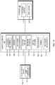
- the particle processing system 10 includes one or more flow-paths for processing particles.
- the particle processing system 10 includes a particle inspection system 11 including one or more detectors 11a for obtaining an output S representative of a particle characteristic for one or more particle in flow-path in the particle processing system 10.
- the particle inspection system 11 may be a primary particle inspection system wherein the one or more detectors 11a are included in or operatively coupled directly or indirectly to the flow-path at or upstream from a particle processing region thereof.
- the particle inspection system 11 may be a secondary particle inspection system, wherein the one or more detectors 11a are included in or operatively coupled directly or indirectly to the flow-path at or downstream from a particle processing region thereof.
- the output S may be used to control downstream processing, for example, downstream sorting, of a detected particle.
- the output S may be used to monitor/evaluate upstream processing of a detected particle or to further process the particle.
- the particle inspection system 11 may include a plurality of detectors.
- the particle inspection system 11 may include a plurality of detectors included in or operatively coupled directly or indirectly to a same flow-path at a same point/region along the flow-path.
- the plurality of detectors may be used to detect a plurality of signals for determining measurements for different particle characteristics at the same point/region along the flow-path.
- the particle inspection system 11 may process raw data from one or more detectors to obtain the output S.
- the particle inspection system 11 may include one or more detectors included in or operatively coupled directly or indirectly to a plurality of flow-paths or a same flow-path at a plurality of points/regions along the flow-path. Such detector multitasking may be advantageous for optimal use of space/resources in the particle processing system 10.
- the particle processing system 10 may include or be operatively associated directly or indirectly with a controller 12, for example, for controlling the particle inspection system 11.
- the controller 12 may be configured to obtain, for example, a measurement value for a particle characteristic based, for example, on the output S from the particle inspection system 11.
- the output may include a measurement value for a particle characteristic.
- the controller 12 may further be configured to analyze the measurement value for the particle characteristic take an action based thereon.
- the controller 12 may be configured to control downstream processing of a detected particle based on an obtained measurement value for the particle characteristic for the detected particle.
- the controller 12 may be used to evaluate an upstream processing of a detected particle and notify a user about and/or adjust, optimize or maintain an operational characteristic of the particle processing system 10 based thereon, for example, if a particle processing error is detected.
- the controller 12 may be implemented in whole or in part via programming associated with a programmable processor, for example, processor 12a.
- the controller 12 may further include or be associated with a user interface 12b.
- the controller 12 is configured to adjust, for example, normalize, calibrate, or standardize, at least a portion of the output S, for example, a measurement value for a particle characteristic.
- Such 15 adjustment of the output S may advantageously provide a common basis for comparing the output S relative to a second output representative of the same particle or characteristic (for example, for a different particle, different detection region, different flow-path, different particle inspection system, and/or different particle processing system) or for relating the output S relative to an output representative of a different particle characteristic.
- adjusted output representative of a same particle characteristic for example, for different particles, different detection regions, different flow-paths, different particle inspection systems, and/or different particle processing systems
- representative of a different particle characteristic may be superimposed so as to allow for the combined analysis/processing thereof. This may enable, for example, visualization and identification of particle populations, for example, across multiple flow-paths/channels (for same or different particle processing systems) and/or across multiple particle inspection systems and provide accurate selection of and processing of sub-populations.
- FIG. 2 an exemplary method 200 for adjusting, for example, normalizing, calibrating or standardizing, an output (for example the output S of Fig. 1 ) is described. It will be appreciated by one of ordinary skill in the art that the method 200 of Fig. 2 may be implemented in whole or in part via programming associated with a programmable processor (for example, processor 12a of Fig. 1 ).
- a programmable processor for example, processor 12a of Fig. 1
- method 200 may include initial steps of dynamic normalization/calibration 210 and velocity-dependent normalization/calibration 220 and 230.
- Dynamic normalization/calibration 210 may be used, for example, to mitigate instrument-related measurement variability (for example, for measurements by the particle inspection system or between particle inspection systems, or for measurement for different particles, different detection regions, different flow-paths, or different particle processing systems) and background signals and/or noise, such as low frequency signal variations (in optical measurements, low frequency signal power variations may be caused, for example by low frequency laser power fluctuations).
- dynamic normalization/calibration 210 may include the following transformation on the output S in : where S N is the output after dynamic normalization/calibration, where and where N and M are constants used to fine tune the normalization/calibration efficacy and end points.
- Dynamic normalization/calibration 210 may advantageously be switched off/bypassed whenever a particle is detected (so as to maintain maximum signal resolution). In exemplary embodiments, dynamic normalization/calibration 210 may not be necessary, for example, if the measurement instrument (e.g. illumination laser and/or detector) is of sufficiently low noise.
- the measurement instrument e.g. illumination laser and/or detector
- Velocity based adjustment 220 and 230 may be used to minimize output variability due to differences in particle velocity (for example, for measurements by the particle inspection system or between particle inspection systems, or for measurement for different particles, different detection regions, different flow-paths, or different particle processing systems). Velocity based adjustment may be applied to minimize intra-signal variability (220) due to differences in particle velocity and/or inter-signal variability (230) due to differences in particle velocity. Thus, velocity based adjustment may advantageously adjust the output, for example, adjust a measurement value for a particle characteristic as determined by area, height, slope, or other features of a particle pulse in the output).
- intra-signal velocity based adjustment 220 may be applied by adjusting, for example, particle pulse area measurement ( A in ) by a factor of: where A N is the adjusted particle pulse area, where v is the particle velocity, and where v is an average particle velocity (for example, a running average of particle velocity).
- inter-signal velocity based adjustment 230 may be applied by adjusting, for example, normalizing, calibrating or standardizing, particle pulse area ( A in ) relative to a common velocity ( v C ): where A C is the particle pulse area adjusted relative to the common velocity ( v C ).
- velocity based adjustment may not be necessary, for example, where velocity variations are negligible or where the impact of velocity variations on the signal is negligible.
- one or more correction factors may be applied to adjust, for example, normalize calibrate or standardize, an output representative of a particle characteristic, for example a measurement value for a particle characteristic.
- the one or more correction factors may advantageously be determined using one or more calibration particles as is described in greater with respect in Fig. 3 .
- the one or more correction factors may be applied in real time, for example, using a matrix mechanism such as described herein.
- both raw and adjusted outputs representative of a particle characteristic may be obtained for further analysis and/or processing. Adjustment of the output may advantageously provide a common basis for comparing/analyzing the output, for example, with respect to a second output for the same or a releatable particle characteristic.
- an output may be representative of a particle characteristic, for example, may include measurement values for a particle characteristic, for a plurality of particles.
- distributions of measurement values for the particle characteristic for a population of particles may be generated, for example, for different particle inspection systems.
- correction factors may be determined, for example, by identifying and correlating related regions in the distributions.
- a suitably trained neural-network or other adaptive learning system could be used to facilitate such identification and correlation.
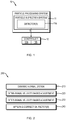
- an exemplary method 300 for facilitating adjustment of measurement detection and/or processing of a particle characteristic by particle inspection system (for example the particle inspection system 11 of Fig. 1 ) in a particle processing system is depicted.
- a particle characteristic a particle characteristic which is detectable by the particle inspection system, is identified.
- the identified particle characteristic may advantageously be relevant to the processing, for example, the sorting of particles, by the particle processing system.
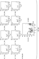
- a matrix mechanism may be established, for example, in flow-channel signal processing electronics.
- the matrix mechanism may advantageously allow for real-time application of correction factors to an output representative of the particle characteristic.
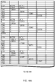
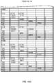
- exemplary correction factors matrixes are depicted. More particularly, each particle inspection system (channel numbers 1-8) may include a matrix of constants that including offsets (produced by the electronics and the optical background) and adjustment constants.
- data may be acquired, for example, by detecting with the particle inspection system an output representative of the particle characteristic for one or more calibration particles.
- calibration particles may be any particles and that calibration particles are note limited to the specific examples thereof presented herein.
- the calibration particles may be selected to include identifiable populations with respect to the particle characteristic.
- florescence brightness (as may be characterized by signal strength for a florescence detector) may be relevant to particle processing.
- a set of calibration particles with known florescence brightness or known relative fluorescence brightness may be identified.
- these particles may include, non-fluorescent (blank or negative) particles, for example, cells, (for example, to help determine the signal pedestal) and at least one easily identifiable fluorescent (positive) particle population, preferably with easily distinguishable cluster of measurement values above pedestal.
- the detected output representative of the particle characteristic for the one or more calibration particles may be compared relative to a standard.
- the detected fluorescence brightness calibration particle(s) may be compared relative to the known fluorescence brightness for the calibration particle(s).
- one or more correction factors for adjusting for example, normalizing, calibrating or standardizing, future measurement or detection of the particle characteristic may be determined.
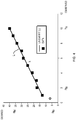
- the correction factors may be determined by using a fitting function such as a linear or other regression algorithm to relate detected measurement values for the particle characteristic for one or more calibration particles to a standard.
- the standard may be selected so as to optimize dynamic range and resolution for measurement or detection of the particle characteristic, for example, for a target population of particles.
- measurement or detection of fluorescence brightness for the calibration particles may be correlated with respect to known/desired brightness, or known/desired relative brightness for the calibration particle(s).
- a cluster of measurement values for the characteristic for a plurality of calibration particles may be used to identify a population of calibration particles.
- one or more clusters of measurement values may be identified and correlated with respect to known/desired brightness or known/desired relative brightness for the corresponding calibration particle population.
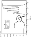
- a pattern of clusters may be used such that it is quickly identifiable to facilitate correlation to a standard. The cluster pattern may be established by selecting a plurality of clusters with a known relative brightness between themselves. Within reason, the greater the number of clusters the more unique the pattern will be. In exemplary embodiments, such as depicted in Fig.
- this calculation may be based on a linear fit L for observed versus known/desired data for two or more clusters resulting in a normalization/calibration constant (slope k) and pedestal (in this case, optical background offset o).
- a multi-dimensional envelope may be applied. This would work well, for example, where the particle characteristic is the overall spectral signature of a particle.
- the choice of calibration particles may be used to define the range and the resolution of the normalized data.
- a specially binned linear-log histogram may be filled, such that greater measurement values, for example, high brightness peaks are effectively compressed without changing the underlying data.
- a cluster finding algorithm may further be applied to eliminate false peaks.
- calculated correction factors may be evaluated by a series of tests, for example, to provide a quality metric for the calibration procedure that can then be used as a part of an automatic validation tool. Feedback may also be obtained for the quality of clusters/peaks used to determine the correction factors.
- Exemplary tests may include but are not limited to proximity tests (outlier detection), and threshold tests (threshold number of channels/spectral measurements which are within or outside of acceptable limits) or other tests.
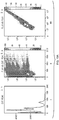
- exemplary peak/cluster detection is depicted for an output representative of a particle characteristic (fluorescence FL3) for a population of calibration particles including a sub-population of blank particles and sup-populations of ultra-rainbow particles (clusters/peaks 2, 3, 4, 5 and 6).
- cluster/peak 2 is not properly identified due to its proximity to the pedestal as determined by the blank particle peak BLK.
- cluster/peak 2 may be advantageously discarded when calculating correction factors.
- calibration particle data may be used to adjust one or more operational parameters of the particle inspection system, for example, to adjust measurement or detection of the particle characteristic by of the particle inspection system, for example relative to a standard. More particularly, operational parameters of the particle inspection system such as laser power, photodetector voltage or gain, flow rate or the like, may be adjusted based on deviations of the output/singal representative of the particle characteristic for the one or more calibration particles relative to a standard. This may be an iterative process, for example, to reduce/minimize such deviations.
- calibration particle data may be used to adjust an algorithm for processing an output representative of a particle characteristic.
- a standard algorithm for example, an algorithm originally configured for processing an output conforming to a standard, may be adjusted based on deviations of the output for the one more calibration particles relative to the standard. In this way, a standard algorithm may be tailored, for example, for a particular particle inspection system.
- the flow-path 400 is a branched flow-path for particle sorting operations.
- the flow-path 400 may be a flow-channel, for example, a microchannel, defined in a substrate, for example, of a microfluidic chip.
- the flow-path 400 may be configured to receive a stream of particles suspended in a carrier fluid in a flow direction.
- the flow-path 400 may include a primary measurement/detection region 410, a processing/sorting region 420 in proximity to the primary measurement/detection region 410 and a branch point 430 downstream of the processing/sorting region 420 where the flow-path 400 branches into a plurality of output branches 400a and 400b and a secondary measurement/detection region 440 downstream of the processing/sorting region 420, for example, downstream of the branch point 430 and along the output branches 400a and 400b of the flow-path 400.
- the flow-path 400 may include or be operatively associated with a primary particle inspection system 410a for measuring or detecting a particle at the primary measurement/detection region 410.
- the primary particle inspection system 410a may be used to obtain an output S 1 representative of a particle characteristic for the particle which may serve as criteria for processing/sorting the particle at the processing/sorting region 420.
- the primary particle inspection system 410a may detect particle velocity, for example, for controlling timing on a particle-by-particle basis. Exemplary apparatus, systems and methods for measuring particle velocity are addressed in U.S. Patent Nos. 6,976,590 and 7,569,788 .
- the primary particle inspection system 410a may be operatively associated with a controller 12 for receiving and analyzing the output S 1 .
- the controller 12 may be operatively associated with a plurality particle inspection systems and/or a plurality of outputs.
- the flow-path 400 may also include or be operatively associated with a particle processing device 420a for selectively processing/sorting particles at the processing/sorting region 420.
- the particle processing device 420a may selectively sort a particle by deflecting it into one of the output branches 400a and 400b of the flow-path 400.
- the flow-path 400 depicted in Fig. 5 includes two output branches 400a and 400b, the present disclosure is not limited to such an embodiment. Indeed, in some embodiments the flow-path 400 may include more than two output branches.
- the particle processing device 420a may be configured such that deflected particles sort into one of one or more "active" branches of the flow-path 400 and non-deflected particles sort into one of one or more "passive" branches of the flow-path 400.
- the particle processing device 420a may include or be operatively coupled directly or indirectly to an actuator.
- the particle processing device 420a may also include or be operatively associated with a controller for controlling the particle processing device 420a, for example, the same controller 12 as for the primary particle inspection system 410a or a different controller.
- the flow-path may 400 may include or be operatively associated with secondary particle inspection systems 440a and 440b for measuring and/or detecting particles at the secondary measurement/detection region 440.
- the secondary particle inspection systems 440a and 440b may produce outputs S 2a and S 2b, , each representative of a particle characteristic, for a processed particles in or flowing from a corresponding one of the output branches 400a and 400b.
- the outputs S 2a and S 2b may be used, for example, to evaluate upstream processing of detected particles or for further processing of the detected particles.
- the secondary particle inspection systems 440a and 140b may be operatively associated with a controller for receiving and analyzing the output S 2a and S 2b , for example, the same controller 12 as for the primary detector 410a or a different controller.
- each of the output S 1 , S 2a and S 2b for example, measurements of a particle characteristic
- each of the output S 1 , S 2a and S 2b may be adjusted, for example, normalized, calibrated or standardized, using the systems, methods and non-transitory storage medium described herein, for example, the methods described with respect to Figs. 2-3 .
- the output S 1 , S 2a and S 2b may be adjustedto allow for inter-relatability.
- adjusted output S 1 , S 2a and S 2b may be collectively analyzed, visualized and/or evaluated.
- the systems, methods and non-transitory storage medium described herein may be applied to superimpose and, in some instances, visualize measurement values for a particle characteristic for different particles, different detection regions, different flow-paths, different particle inspection systems, and/or different particle processing systems.
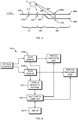
- an exemplary particle processing system 500 is depicted, including a plurality of flow-channels 510a and 510b. Particles entering the flow-channels 510a and 510b may be measured or detected using one or more particle inspection systems 520.
- a control system 530 including a computer and/or electronics, may be used to adjust an output representative of a same particle characteristic for each of the flow-channels 510a and 510b, according to the systems, methods and non-transitory storage medium described herein.
- the adjusted outputs for both flow-channels 510a and 510b may then be superimposed for further analysis and processing.
- the superimposed outputs may be displayed on a display 540 to facilitate particle processing (for example, to facilitate selection one or more particle subpopulations for sorting).
- FIG. 7 depicts the ability to adjust 610 and superimpose 620 (for combined processing/analysis) measurements of a particle characteristic across a plurality flow-paths, for example, flow channels 630, particle processing systems, for example instruments 640, and locations, for example, facilities 650, according to the present disclosure.
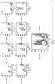
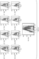
- Fig. 8 bivariate plots (light extinction versus fluorescence) are depicted for a plurality of flow-channels individually and in combination before (A) and after (B) output adjustment.
- the data was obtained for a three-marker particle population including blank, dim positive, and bright positive particles (clusters 801, 802 and 803) as excited by a 532nm laser and detected using a spectral waveband of 560-600nm.
- the combined plots clearly demonstrate the effect and accuracy of adjusting the output representative of fluorescence for each of the flow-channels.
- data for multiple flow-channels may be viewed and analyzed, collectively. For example, population statistics may be determined for multiple flow-channels.
- particle sub-populations across multiple flow-channels may be easily and quickly identified, for example, further processing.
- the determination of particle sub-populations may be automated by applying processing algorithms tailored to the standard for example algorithms for thresholding/grouping relative to normalized measurement values. It will be appreciated, that, in exemplary embodiments, the multiple flow-channels may be in different particle processing systems, and that the different particle processing systems, may be in different geographic locations.
- Fig. 9 depicts two-color florescence bivariate plots (fluorescence 1 versus fluorescence 2) for a plurality of flow-channels individually and in combination before (A) and after (B) output adjustment.
- the combined plots clearly demonstrate the effect and accuracy of adjusting the output representative of fluorescence 1 and fluorescence 2 for each of the flow-channels.
- the data was obtained for a three-marker particle population as evidenced by the three population clusters (901, 902 and 903)
- Fig. 10 depicts bivariate plots of (I) light extinction versus particle size, (II) fluorescence versus light extinction, and (III) fluorescence 3 versus fluorescence 1, for a combined plurality of flow-channels before and after output adjustment.
- the data was obtained for a six-marker population (clusters 1001-1006).
- correction factors may be applied to adjust future measurement or detection of a particle characteristic.
- Fig. 11 data for a population of CD-3 labeled cells is adjusted by applying pre-set correction factors (previously determined using calibration particles) and combined across multiple flow channels. This may be particularly useful for calculating/analyzing population statistics and/or identifying/analyzing rare sub-populations, for example for further processing steps such as cell sorting, enrichment, or purification.
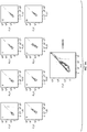
- Fig. 15 bivariate plots (fluorescence versus particle size) are depicted for a combined plurality of output channels before (FLU2) and after (FLU2 normalized) output adjustment. Pre-adjustment it is very difficult to distinguish between clusters/peaks. Post adjustment, measurement values for particles with corresponding brightness converge resulting in clearly identifiable clusters/peaks.
- Fig. 16 the relationship between the raw and adjusted data of Fig. 15 is depicted. More particularly, FLU2 (y axis) is plotted in relation to against FLU2 normalized (x axis). The circled regions represent shades of the same population (e.g., as determined by particle size) resulting from the different channels lining up in the x-axis.
- Detectors may be any detector for measureing or detecting a particle including but not limited to optical detectors, electrical detectors, magnetic detectors, acoustic detectors, electromagnetic wave detectors and the like. Detectors may advantageously be used to detect a particle or an absence of a particle in a flow-channel/flow-path. Detectors may further be used to detect one or more particle characteristics, for example, for facilitating identification/classification of particles.
- Exemplary optical detector configurations are provided in Figs. 10-13 . of U.S. Application No. 61/429,339, filed January 3, 2011 , entitled “Method and Apparatus for Monitoring and Optimizing Particle Sorting".
- Detector configurations are not limited to optical configurations. Indeed, other detection approaches may be applied instead of or in conjunction with optical means. These approaches may include but are not limited to (i) passive or active electrical detection including but not limited to conductance, capacitance, RF field monitoring through devices fabricated on the microchip, or located off-chip near channels of interest (ii) magnetic detection, such as using a Hall-effect device or other field probes located in the proximity of flow-channels and (iii) acoustic detection such as ultrasound absorption, reflection, scatter or the like using on-board or remote devices, (iv) chemical or molecular detection devices including but not limited to devices such as mass spectroscopy devices.
- passive or active electrical detection including but not limited to conductance, capacitance, RF field monitoring through devices fabricated on the microchip, or located off-chip near channels of interest
- magnetic detection such as using a Hall-effect device or other field probes located in the proximity of flow-channels
- acoustic detection such as ultrasound absorption, reflection, scatter
- a particle may be detected by an analog level, for example by surpassing (going above or below) a threshold which produces a detectable voltage change.
- the signal may be used to characterize, identify or count the particle.
- Temporal information may be used to determine the velocity of the particle, the time elapsed from the detection of the particle at another location, the expected time that the particle will reach a selected position, or the like.
- conductive traces may be used to form an electrode array across or along one or more flow-paths where the absence or presence of a particle adjusts the conductivity or other electrical measurement, for example, capacitance, resistance, inductance of the fluid path between any electrode pair.
- the conductive traces may be formed on one substrate of a microfluidic chip prior to fusing a second substrate to provide contact with flow-path.
- the conductivity of electricity of the electrical circuit may change and be detected with appropriate electronic processing tools such as an analog current meter or a computer.
- An exemplary electrode array is described with respect to Figs. 14 and 15 of U.S. Application No. 61/429,339 .
- Detector configurations and approaches described may be applied for both modular and integrated embodiments of a particle processing system. It will be appreciated by one of ordinary skill in the art that a particle characteristic may be measured using data from any combination of detector configurations. Indeed, the use of multiple parameter detection and/or multi-dimensional characteristics may advantageously enable finer detection of subpopulations of particles.
- the systems and methods presented herein may include one or more programmable processing units having associated therewith executable instructions held on one or more computer readable medium, RAM, ROM, hard drive, and/or hardware.
- the hardware, firmware and/or executable code may be provided, for example, as upgrade module(s) for use in conjunction with existing infrastructure (for example, existing devices/processing units).
- Hardware may, for example, include components and/or logic circuitry for executing the embodiments taught herein as a computing process.
- Displays and/or other feedback means may also be included to convey detected/processed data, for example adjusted output representative of a particle characteristic.
- the display and/or other feedback means may be stand-alone or may be included as one or more components/modules of the processing unit(s).
- the display and/or other feedback means may be used to facilitate selection of one or more particle populations/sub-populations for processing.
- a "processor,” “processing unit,” “computer” or “computer system” may be, for example, a wireless or wire line variety of a microcomputer, minicomputer, server, mainframe, laptop, personal data assistant (PDA), wireless e-mail device (for example, “BlackBerry,” “Android” or “Apple,” trade-designated devices), cellular phone, pager, processor, fax machine, scanner, or any other programmable device configured to transmit and receive data over a network.
- Computer systems disclosed herein may include memory for storing certain software applications used in obtaining, processing and communicating data. It can be appreciated that such memory may be internal or external to the disclosed embodiments.
- the memory may also include non-transitory storage medium for storing software, including a hard disk, an optical disk, floppy disk, ROM (read only memory), RAM (random access memory), PROM (programmable ROM), EEPROM (electrically erasable PROM), flash memory storage devices, or the like.
- non-transitory storage medium for storing software, including a hard disk, an optical disk, floppy disk, ROM (read only memory), RAM (random access memory), PROM (programmable ROM), EEPROM (electrically erasable PROM), flash memory storage devices, or the like.
- the environment may include a computing device 102 which includes one or more media for storing one or more computer-executable instructions or code for implementing exemplary embodiments.
- memory 106 included in the computing device 102 may store computer-executable instructions or software, for example instructions for implementing and processing every module of the application 120.
- the computing device 102 is one example of the controller 12 depicted in Figure 1 .
- the computing device 102 also includes processor 104, and, one or more processor(s) 104' for executing software stored in the memory 106, and other programs for controlling system hardware.
- Processor 104 and processor(s) 104' each can be a single core processor or multiple core (105 and 105') processor.
- Virtualization can be employed in computing device 102 so that infrastructure and resources in the computing device can be shared dynamically. Virtualized processors may also be used with application 120 and other software in storage 108.
- a virtual machine 103 can be provided to handle a process running on multiple processors so that the process appears to be using one computing resource rather than multiple. Multiple virtual machines can also be used with one processor.
- a hardware accelerator 119 such as implemented in an ASIC, FPGA, or the like, can additionally be used to speed up the general processing rate of the computing device 102.
- the memory 106 may comprise a computer system memory or random access memory, such as DRAM, SRAM, EDO RAM, or the like.
- the memory 106 may comprise other types of memory as well, or combinations thereof.
- a user may interact with the computing device 102 through a visual display device 114, such as a computer monitor, which may display one or more user interfaces 115.
- the visual display device 114 may also display other aspects or elements of exemplary embodiments, for example, adjusted measurement values for a particle characteristic.
- the computing device 102 may include other I/O devices such a keyboard or a multiple-point touch interface 110 and a pointing device 112, for example a mouse, for receiving input from a user.
- the keyboard 110 and the pointing device 112 may be connected to the visual display device 114.
- the computing device 102 may include other suitable conventional I/O peripherals.
- the computing device 102 may further comprise a storage device 108, such as a hard-drive, CD-ROM, or other storage medium for storing an operating system 116 and other programs, for example, a program 120 including computer executable instructions for, calculating correction factors and/or adjusting output.
- a storage device 108 such as a hard-drive, CD-ROM, or other storage medium for storing an operating system 116 and other programs, for example, a program 120 including computer executable instructions for, calculating correction factors and/or adjusting output.
- the computing device 102 may include a network interface 118 to interface to a Local Area Network (LAN), Wide Area Network (WAN) or the Internet through a variety of connections including, but not limited to, standard telephone lines, LAN or WAN links (for example, 802.11, T1, T3, 56kb, X.25), broadband connections (for example, ISDN, Frame Relay, ATM), wireless connections, controller area network (CAN), or some combination of any or all of the above.
- the network interface 118 may comprise a built-in network adapter, network interface card, PCMCIA network card, card bus network adapter, wireless network adapter, USB network adapter, modem or any other device suitable for interfacing the computing device 102 to any type of network capable of communication and performing the operations described herein.
- the computing device 102 may be any computer system such as a workstation, desktop computer, server, laptop, handheld computer or other form of computing or telecommunications device that is capable of communication and that has sufficient processor power and memory capacity to perform the operations described herein.
- the computing device 102 can be running any operating system such as any of the versions of the Microsoft® Windows® operating systems, the different releases of the Unix and Linux operating systems, any version of the MacOS® for Macintosh computers, any embedded operating system, any real-time operating system, any open source operating system, any proprietary operating system, any operating systems for mobile computing devices, or any other operating system capable of running on the computing device and performing the operations described herein.
- the operating system may be running in native mode or emulated mode.
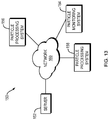
- Fig. 13 illustrates an exemplary network environment 150 suitable for a distributed implementation of exemplary embodiments.
- the network environment 150 may include a server 152 coupled relative to a network 160.
- the server 152 may include an application 120", which may include computer readable instructions for carrying out the methods disclosed herein.
- the network environment 150 may further includes one or more particle processing systems, for example particle processing systems 156 and 158, coupled, relative to the network 160.
- Particle processing systems 156 and 158 may be particle processing systems such as described above with respect to Figs. 1 and 5 , and may include an application 120 which may include computer readable instructions for carrying out the methods disclosed herein.
- the particle processing systems 156 and 158 may also be located at geographically remote locations.
- the network environment 150 may also include a particle monitoring system 154 coupled relative to the network 160 for receiving data from the one or more particle processing systems across the network 160.
- the particle monitoring system may include an application 120' which may include computer readable instructions for carrying out the methods disclosed herein.
- the server 152, particle monitoring system 154 and/or particle processing systems 156 and/or 158 may be implemented at least in part via the computing device 102 of Fig. 12 .
- the network interface 118 of the computing device 102 may enables the server 152 and/or particle monitoring system 154 to communicate with / receive data from the particle processing systems 156 and 158 through the communication network 160.
- the communication network 160 may include Internet, intranet, LAN (Local Area Network), WAN (Wide Area Network), MAN (Metropolitan Area Network), wireless network (for example, using IEEE 802.11 or Bluetooth), or other network configurations.
- the network may use middleware, such as CORBA (Common Object Request Broker Architecture) or DCOM (Distributed Component Object Model) to allow a computing device on the network 160 to communicate directly with another computing device that is connected to the network 160.
- middleware such as CORBA (Common Object Request Broker Architecture) or DCOM (Distributed Component Object Model) to allow a computing device on the network 160 to communicate directly with another computing device that is connected to the network 160.
- the server 152 and/or particle monitoring system 154 may provide the particle processing systems 156 and 158 with software components or products under a particular condition, such as a license agreement.
- the software components or products may include one or more components of the application 120 of Fig. 12 .
- the server 152 or particle monitoring system 154 may analyze and compare adjusted output representative of a particle characteristic for the plurality of particle processing systems 156 and 158 across the network environment 150.
Landscapes
- Chemical & Material Sciences (AREA)
- Health & Medical Sciences (AREA)
- Biochemistry (AREA)
- Immunology (AREA)
- Physics & Mathematics (AREA)
- Pathology (AREA)
- Life Sciences & Earth Sciences (AREA)
- Analytical Chemistry (AREA)
- General Physics & Mathematics (AREA)
- General Health & Medical Sciences (AREA)
- Dispersion Chemistry (AREA)
- Engineering & Computer Science (AREA)
- Signal Processing (AREA)
- Nuclear Medicine, Radiotherapy & Molecular Imaging (AREA)
- Investigating, Analyzing Materials By Fluorescence Or Luminescence (AREA)
- Optical Measuring Cells (AREA)
- Investigating Or Analysing Materials By Optical Means (AREA)
- Automatic Analysis And Handling Materials Therefor (AREA)
- Sampling And Sample Adjustment (AREA)
Description
- The present disclosure relates to particle processing, for example particle sorting. More particularly, the present disclosure relates to normalization/calibration of particle measurements used for particle processing.
- In the fields of biotechnology, biology and medicine, there is a need for high throughput processing (for example, analysis and sorting) of particles. High throughput particle processing may be facilitated by utilizing multiple flow-paths in parallel. Furthermore, multiple particle processing systems, in the same or different physical locations, may be utilized to carry out the same or similar particle processing operations.
- Conventionally, particle processing involves analyzing one or more particles within a flow-path and processing (for example, sorting) the particle(s) based on such analysis. As described in Application No.
U.S. Application No. 61/429,339
particle processing. These and other needs are addressed by way of the present disclosure. -
US 2008/0087068 A1 is directed to a method for monitoring and controlling one or more parameters of a flow cytometer measuring system in real time.US 2008/0108146 A1 is directed to a calibration method for a flow cytometer with a multichannel detector module.WO 2009/146036 A2 is directed to a system and method for validating differences between measured fluorescence intensities obtained from a fluorescence-based instrument.US 2006/244964 A1 is directed to a system and method for determining particle parameters in a particle analysis system. - Systems, methods and non-transitory computer readable storage medium are presented herein related to particle detection using a particle inspection system in a particle processing system.
- In exemplary embodiments, a particle processing system is presented including a particle inspection system configured to detect a particle characteristic of a particle flowing in a first flow path of the particle processing system; and a processor programmed to process in real time a first output of the particle inspection system representative of the particle characteristic detected from at least one particle to generate a calibrated output representative of the particle characteristic for the at least one particle to provide a common basis for comparing the calibrated output to a second output representative of the particle characteristic obtained for a different particle in a different flow path or in a different region of the first flow path; collectively analyze the calibrated output and the second output to at least determine one of a population statistic or identify a sub-population; and sort other particles based on at least one of the determined population statistic or the identified sub-population.
- In other examples, the output may be derived from analyzing data from one or more detectors in the particle inspection system. In some examples the adjustment of the output standardizes measurement of the particle characteristic. In other examples, the collectively analyzed outputs are superimposed and viewed in combination on a display. In some examples, the different flow path is provided in a different particle inspection system. In yet other examples, the adjustment of the output may provide a common basis for relating the calibrated output relative to an output representative of a different particle characteristic. In some examples, the adjustment of the output may include calibrating the output based on a velocity of the particle. For example, the adjustment of the output may include calibrating the output with respect to an average particle velocity (such as adjusting the output by a factor of a velocity of the particle over an average particle velocity) or calibrating the output with respect to a standard particle velocity (such as adjusting the output by a factor of a velocity of the particle over a standard particle velocity). In other examples, the adjustment of the output may include applying one or more correction factors which may be applied, for example, using a matrix mechanism. In some examples, adjustment of the output may include adjusting a baseline for the output. In other examples, adjusting the baseline may includes mitigating baseline variability, for example, by dividing the baseline by an average baseline.
- A particle processing system is described, including a particle inspection system configured to detect a characteristic for one or more calibration particles flowing in a flow-path of the particle processing system; and a processor programmed to compare an output representative of the particle characteristic for the one or more calibration particles relative to a standard and take an action based on a result of the comparing the output to the standard. The processor may be further programmed to determine, based on the comparing of the output relative to the standard, one or more correction factors for calibrating data obtained by the particle inspection system, for example using a fitting function or multidimensional envelope to relate the one the output to the standard. The processor may be further programmed to adjust, based on the comparing of the output relative to the standard, one or more operating parameters of the particle inspection system. The processor may be further programmed to determine, based on the comparing of the output relative to the standard, one or more correction factors for tailoring an algorithm for processing or analyzing data obtained by the particle inspection system. The comparing the output relative to the standard may include identifying one or more clusters of measurement values for the particle characteristic, each cluster representative of a population of the calibration particles. The one or more clusters may, for example, be determined by using a cluster finding algorithm and/or based on a pattern of clusters.
- A particle processing system is described, including a particle inspection system configured to detect a characteristic for a particle flowing in a flow-path of the particle processing system; and a processor programmed to adjust a first output of the particle inspection system representative of the particle characteristic for the particle to provide a common basis for comparing the adjusted first output relative to a second output. The second output may be representative of the same particle characteristic. The second output may be representative of a different particle characteristic. The second output may be representative of a particle characteristic for a different particle. The second output may be representative of a particle characteristic for a particle in a different detection region in the flow-path. In other examples, the second output may be representative of a particle characteristic for a particle in a different flow-path in the particle processing system. The second output may be representative of a particle characteristic for a particle in a different particle processing system. The second output may be detected with a different particle inspection system. The processor may be further configured to superimpose the first and second outputs. Tthe superimposed first and second outputs may be viewed in combination on a display.
- A particle processing system is described, including a particle inspection system configured to detect a characteristic for a particle flowing in a flow-path of the particle processing system; and a processor programmed to superimpose a first output of the particle inspection system representative of the particle characteristic for the particle relative to a second output. The second output may be representative of the same particle characteristic. The second output may be representative of a different particle characteristic. The second output may be representative of a particle characteristic for a different particle. The second output may be representative of a particle characteristic for a particle in a different detection region in the flow-path. The second output may be representative of a particle characteristic for a particle in a different flow-path in the particle processing system. The second output may be representative of a particle characteristic for a particle in a different particle processing system. The second output may be detected with a different particle inspection system. The superimposing the first and second outputs includes adjusting the first output to provide a common basis for comparing the adjusted first output relative to the second output. The superimposed first and second outputs may be viewed in combination on a display.
- A particle monitoring system is described, including a receiver configured to receive data from a plurality of particle inspections systems concerning a population of particles, and a processor programmed to processes the received data to account for measurement or processing variability amongst the plurality of particle inspection systems. The plurality of particle inspection systems may be co-located on a microfluidic chip or associated with a same particle processing system. The plurality of particle inspection systems may be located on different microfluidic chips or associated with different particle processing systems. The plurality of particle inspection systems may be located at geographically distinct locations.
- A particle processing system is described, including a particle inspection system configured to detect a characteristic for a calibration particle flowing in a flow-path of the particle processing system; and a processor programmed to determine a measurement value for the characteristic for the calibration particle, compare the measurement value to a standard; and take an action based on a result of the comparing the measurement value to the standard. The processor may be further programmed to determine, based on the comparing of the measurement value relative to the standard, one or more correction factors for calibrating data obtained by the particle inspection system, for example, wherein the one or more correction factors are determined by using a fitting function to relate the measurement value to the standard. The processor may be further programmed to adjust, based on the comparing of the measurement value relative to the standard, one or more operating parameters of the particle inspection system. The processor may be programmed to determine, based on the comparing of the measurement value relative to the standard, one or more correction factors for tailoring an algorithm for processing or analyzing data obtained by the particle inspection system.
- In a further embodiment, a method is presented including steps of measuring with a particle inspection system a particle characteristic of a particle flowing in a first flow-path of the particle processing system; processing in real time a first output from the particle inspection system representative of a particle characteristic detected from at least one particle to generate a calibrated output representative of the particle characteristic for the at least one particle to provide a common basis for comparing the calibrated output to a second output representative of the particle characteristic obtained for a different particle in a different flow path or in a different region of the first flow path; collectively analyzing the calibrated output and the second output to at least determine one of a population statistic or identify a sub-population; and sorting other particles based on at least one of the determined population statistic or the identified sub-population. In some examples, the calibrating the output may standardize measurement of the particle characteristic. In some examples, collectively analyzing includes superimposing and viewing the outputs in combination on a display. In some examples, the different flow path is provided in a different particle inspection system. In other examples, the different flow path is provided in a different region of the flow-path or in a different flow-path. In yet other examples, the second output is representative of a different particle characteristic. In some examples, the calibrating the output may include calibrating the output based on a velocity of the particle. In other examples, the calibrating the output may include adjusting a baseline for the output.
- A method is described including steps of detecting with a particle inspection system a characteristic for one or more calibration particles flowing in a flow-path of the particle processing system; determining an output representative of the characteristic for the one or more calibration particles; comparing the output relative to a standard; and taking an action based on a result of the comparing the output relative to the standard. The action may include calculating, based on the comparing of the output relative to the standard, one or more correction factors for calibrating data obtained by the particle inspection system, for example, wherein the one or more correction factors may be determined by using a fitting function or a multi-dimensional envelope to relate the output to the standard. The action may include adjusting, based on the comparing of the output relative to the standard, one or more operating parameters of the particle inspection system. The action may include calculating, based on the comparing of the output relative to the standard, one or more correction factors for tailoring an algorithm for processing or analyzing data obtained by the particle inspection system. The calibration particles may be selected to include identifiable populations with respect to the particle characteristic. The standard may include reference values for the particle characteristic for one or more calibration particles or for one or more populations of calibration particles. The standard may be selected to set a dynamic range or resolution for the particle characteristic, for example, to optimize a dynamic range or resolution for the particle characteristic with respect to a target population of particles. The comparing the output relative to the standard includes identifying one or more clusters of measurement values for the particle characteristic, each cluster representative of a population of the calibration particles.
- A method is described, including steps of detecting, with a particle inspection system a first output representative of a particle characteristic for a particle flowing in a flow path of a particle processing system; and adjusting the first output of a particle inspection system to provide a common basis for comparing the adjusted first output relative to a second output. The second output may be representative of the same particle characteristic. The second output may be representative of a different particle characteristic. The second output may be representative of a particle characteristic for a different particle. The second output may be representative of a particle characteristic for a particle in a different detection region in the flow-path. The second output may be representative of a particle characteristic for a particle in a different flow-path in the particle processing system. The second output may be representative of a particle characteristic for a particle in a different particle processing system. The second output may be detected with a different particle inspection system. The processor may be further configured to superimpose the first and second outputs. The superimposed first and second outputs may be viewed in combination on a display. The superimposed first and second outputs may be viewed in combination on a display.
- A method is described, including steps of detecting, with a particle inspection system a first output representative of a particle characteristic for a particle flowing in a flow path of a particle processing system; and superimposing the first output relative to a second output. The second output may be representative of the same particle characteristic. The second output may be representative of a different particle characteristic. The second output may be representative of a particle characteristic for a different particle. The second output may be representative of a particle characteristic for a particle in a different detection region in the flow-path. The second output may be representative of a particle characteristic for a particle in a different flow-path in the particle processing system. The second output may be representative of a particle characteristic for a particle in a different particle processing system. The second output may be detected with a different particle inspection system. The superimposing the first and second outputs includes adjusting the first output to provide a common basis for comparing the adjusted first output relative to the second output. The superimposed first and second outputs may be viewed in combination on a display.
- A method is described, including steps of detecting with a particle inspection system a characteristic for a calibration particle flowing in a flow-path of the particle processing system; determining a measurement value for the characteristic for the calibration particle; comparing the measurement value to a standard; and taking an action based on a result of the comparing the measurement value to the standard. The action may include determining, based on the comparing of the measurement value relative to the standard, one or more correction factors for calibrating data obtained by the particle inspection system, for example, wherein the one or more correction factors are determined by using a fitting function to relate the measurement value to the standard. The action may include adjusting, based on the comparing of the measurement value relative to the standard, one or more operating parameters of the particle inspection system. The action may include determining, based on the comparing of the measurement value relative to the standard, one or more correction factors for tailoring an algorithm for processing or analyzing data obtained by the particle inspection system.
- In exemplary embodiments, a non-transitory computer-readable storage medium is presented storing computer executable instructions for measuring with a particle inspection system, a particle characteristic of a particle flowing in a first flow path of a particle processing system; processing in real time a first output from the particle inspection system representative of a particle characteristic detected from at least one particle to generate a calibrated output representative of the particle characteristic for the at least one particle to provide a common basis for comparing the calibrated output to a second output representative of the particle characteristic obtained for a different particle in a different flow path or in a different region of the first flow path; collectively analyzing the calibrated output and the second output to at least determine one of a population statistic or identify a sub-population; and sorting other particles based on at least one of the determined population statistic or the identified sub-population.
- A non-transitory computer-readable storage medium is described, storing computer executable instructions for comparing an output of a particle inspection system representative of a particle characteristic for one or more calibration particles flowing in a flow-path of a particle processing system relative to a standard; and taking an action based on a result of the comparing the output to the standard.
- Additional features, functions and benefits of the disclosed systems, methods and medium will be apparent from the description which follows, particularly when read in conjunction with the appended figure.
-
-
Figure 1 depicts and exemplary particle processing system, according to the present disclosure. -
Figure 2 depicts an exemplary method for adjusting an output of a particle inspection system representative of a particle characteristic for a particle in a flow path of a particle processing system, according to the present disclosure. -
Figure 3 depicts an exemplary method for facilitating adjustment of measurement detection and/or processing of a particle characteristic by particle inspection system in a particle processing system, according to the present disclosure. -
Figure 4 depicts using a fitting function to correlate an output of a particle inspection system representative of a particle characteristic for a plurality of calibration particles in a flow path of a particle processing system relative to a standard, according to the present disclosure. -
Figure 5 depicts an exemplary flow-path for a particle processing system, according to the present disclosure. -
Figure 6 depicts an exemplary particle processing system according to the present disclosure. -
Figure 7 depicts adjustment and processing of measurements across an exemplary network of particle processing systems, according to the present disclosure. -
Figure 8 depicts light extinction versus fluorescence for a plurality of flow-channels individually and in combination before and after measurement adjustment, according to the present disclosure. -
Figure 9 depicts two-color florescence bivariate plots for a plurality of flow-channels individually and in combination before and after measurement adjustment, according to the present disclosure. -
Figure 10 depicts bivariate plots of light extinction versus particle size, fluorescence versus light extinction, andfluorescence 3 versusfluorescence 1, for a combined plurality of flow-channels before and after measurement adjustment, according to the present disclosure. -
Figure 11 depicts data for a population of CD-3 labeled cells which is adjusted and combined across multiple flow channels, according to the present disclosure. -
Figure 12 depicts an exemplary computing environment, according to the present disclosure. -
Figure 13 depicts an exemplary network environment, according to the present disclosure. -
Figure 14 depicts exemplary peak/cluster detection, according to the present disclosure. -
Figure 15 depicts fluorescence versus particle size for a combined plurality of output channels before and after measurement adjustment, according to the present disclosure. -
Figure 16 depicts the relationship between the raw and adjusted data ofFig. 15 , according to the present disclosure. -
Figure 17 depicts an exemplary brightness table for calibration particles, according to the present disclosure. -
Figure 18 depicts exemplary correction factors matrixes for a plurality of flow-channels, according to the present disclosure. - Systems, methods and non-transitory storage medium are disclosed herein for adjusting for example, normalizing, calibrating and/or standardizing, an output, for example a measurement value, of a particle inspection system representative of a particle characteristic for a particle in a flow-path of a particle processing system. In some embodiments, the output may be adjusted to reduce/minimize instrument-related measurement variability, for example, for measurements by the particle inspection system or between particle inspection systems, or for measurement for different particles, different detection regions, different flow-paths, or different particle processing systems. In other embodiments, the output may be adjusted to reduce/minimize particle-velocity-related measurement variability, for example, for measurements by the particle inspection system or between particle inspection systems, or for measurement for different particles, different detection regions, different flow-paths, or different particle processing systems. In some embodiments, the output may be adjusted to reduce/minimize baseline variability (for example, due to low frequency power fluctuations in a light source in the case of optical detection, or the like), for example, for measurements by the particle inspection system or between particle inspection systems, or for measurement for different particles, different detection regions, different flow-paths, or different particle processing systems.
- In some embodiments, the systems, methods and non-transitory storage medium disclosed herein may advantageously provide a common basis or baseline for comparing outputs representative of a same particle characteristic (for example, for different particles, different detection regions, different flow-paths, different particle inspection systems, and/or different particle processing systems) or for relating outputs representative of different particle characteristics. Thus, for example, a particle inspection system may be used to measure or detect a particle characteristic for a particle in a flow-path of a particle processing system. One or more corrective factors may then be applied to adjust, for example, normalize, calibrate, or standardize, an output from the particle inspection system representative of the particle characteristic.
- In other embodiments, one or more calibration particles may be used to adjust measurement, detection and/or processing of a particle characteristic by a particle inspection system. For example, the particle inspection system may be used to measure or detect a particle characteristic for one or more calibration particles in a flow-path of a particle processing system. An output representative of the particle characteristic for the one or more calibration particles may then be compared relative to a standard, for example to determine a deviation therefrom and/or a correlation thereto. In some embodiments, measurement or detection of the particle characteristic, for example, for another particle, may be adjusted based on the comparison. For example, in some embodiments, measurement or detection of the particle characteristic may be adjusted by calculating and applying one or more correction factors. In other embodiments, measurement or detection of the particle characteristic may be adjusted by changing one or more operating parameters of the particle inspection system (for example light source power). In exemplary embodiments, measurement or detection of the particle characteristic may be adjusted to conform to the standard. In some embodiments, processing of the particle characteristic may be adjusted, based on the comparison. In exemplary embodiments, processing of the particle characteristic may include applying a processing algorithm as a function of the particle characteristic, for example, an algorithm for sorting particles as a function of the particle characteristic. Thus, in some embodiments processing of the particle characteristic may be adjusted by tailoring a standard processing algorithm for the particle inspection system.
- Particle characteristics may include optical characteristics (fluorescence, scatter, absorbance, extinction, reflection, refraction, polarization, luminescence, chemiluminescence, phosphorescence, spectral/color), electrical characteristics, electromagnetic characteristics, magnetic characteristics, plasmonic characteristics, acoustic characteristics, chemical characteristics, biological characteristics, molecular characteristics, mechanical characteristics, or the like. In some embodiments, particle characteristics may be multi-dimensional for example, a multi-dimensional spectral/color measurement (RGB, CMYK, CIELAB, CIEXYZ, and the like). In exemplary embodiments, a measurement of a particle characteristic may be derived by processing/analyzing data from one or more detectors. Exemplary particle characteristics which may be derived by processing/analyzing data from one or more detectors may include particle size, geometry, volume, surface area, shape, elipticity, velocity, refractive index, granularity, porosity, conductivity, identity, type, phenotype, protein or molecular expression, biological pathway data, genetic content, live/dead state, function or the like.
- Particle processing systems, according to the present disclosure, preferably utilize microfluidics and may comprise a closed-channel system for processing particles. Microfluidic particle processing technology takes advantages of a closed, sterile, and scalable approach to efficiently and/or quickly process large numbers of particles. To this end, a plurality of flow-channels may be combined, for example, on a single microfluidic chip substrate. Particle detection, analysis and/or processing (for example, sorting) functionalities may further interface with the chip or be included thereon.
- The terms flow-path and flow-channel as used herein refer to a pathway formed in or through a medium that allows for movement of fluids, such as liquids and gases. Typical flow-channels in a microfluidic system have cross-sectional dimensions between about 1.0 µη and about 500 µ
 η. In some embodiments, flow-channels have cross- sectional dimensions between about 25 µη and about 250 µη. In further embodiments, flow-channels have cross- sectional dimensions between about 50 µη and about 200 µη. One of ordinary skill in the art will be able to determine appropriate channel dimensions, for example, cross-sectional dimension, length, volume, or the like, of a flow-channel. A flow-channel can have any selected shape or arrangement, examples of which include but are not limited to a linear or non-linear configuration, a U-shaped configuration, a V- shaped configuration, a D-shaped configuration, a C-shaped configuration, a circular configuration, oval configuration, rectangular configuration or the like.
 - The term "particle" refers to a discrete unit of matter. For example, particles may include molecules, cells, agglomerates, or the like. Particles may also refer to (macro) molecular species such as proteins, enzymes, polynucleotides, or the like. In some embodiments, particles may be between lnm and 10mm in diameter. In other embodiments, particles may be between 100 nm and 200 µη in diameter. In yet other embodiments, particles may be between 1 µη and 15 µη in diameter. Particles may be naturally occurring or synthetic, or may combine natural and synthetic components within a single particle. Particles may refer to biological particles. For example, particles may include cells (for example, blood platelets, white blood cells, tumorous cells or embryonic cells, spermatozoa, to name a few), liposomes, proteoliposomes, yeast, bacteria, viruses, pollens algae, or the like. Particles may also refer to non-biological particles. For example, particles may include cells (for example, blood platelets, white blood cells, tumorous cells or embryonic cells, spermatozoa, to name a few), liposomes, proteoliposomes, yeast, bacteria, viruses, pollens algae, or the like. Particles may also refer to non-biological particles. For example, particles may include metals, minerals, polymeric substances, glasses, ceramics, composites, or the like. In exemplary embodiments, particles may include cells or beads with fluorochrome conjugated antibodies.
- The term "detector," as used herein, refers to a device for detecting data. Detected data may, for example, be relevant to determining an output representative of a particle characteristic for a particle in a flow-path of a particle processing system.
- The terms "upstream" and "downstream" are referenced relative to a directional flow of particles in a flow-path.
- The term "standard" as used herein refers to a value, reference or reference point against which a measurement or detection may be evaluated.
- With initial reference to
Fig. 1 , an exemplaryparticle processing system 10 is depicted. Theparticle processing system 10 includes one or more flow-paths for processing particles. Theparticle processing system 10 includes aparticle inspection system 11 including one or more
detectors 11a for obtaining an output S representative of a particle characteristic for one or more particle in flow-path in theparticle processing system 10. In some embodiments, theparticle inspection system 11 may be a primary particle inspection system wherein the one ormore detectors 11a are included in or operatively coupled directly or indirectly to the flow-path at or upstream from a particle processing region thereof. In other exemplary embodiments, theparticle inspection system 11 may be a secondary particle inspection system, wherein the one ormore detectors 11a are included in or operatively coupled directly or indirectly to the flow-path at or downstream from a particle processing region thereof. In some embodiments, such as where theparticle inspection system 11 is a primary particle inspection system, the output S may be used to control downstream processing, for example, downstream sorting, of a detected particle. In other embodiments, such as where theparticle inspection system 11 is a secondary particle inspection system, the output S may be used to monitor/evaluate upstream processing of a detected particle or to further process the particle. In exemplary embodiments, theparticle inspection system 11 may include a plurality of detectors. For example, theparticle inspection system 11 may include a plurality of detectors included in or operatively coupled directly or indirectly to a same flow-path at a same point/region along the flow-path. In some embodiments, the plurality of detectors may be used to detect a plurality of signals for determining measurements for different particle characteristics at the same point/region along the flow-path. In exemplary embodiments theparticle inspection system 11 may process raw data from one or more detectors to obtain the output S. In some embodiments theparticle inspection system 11 may include one or more detectors included in or operatively coupled directly or indirectly to a plurality of flow-paths or a same flow-path at a plurality of points/regions along the flow-path. Such detector multitasking may be advantageous for optimal use of space/resources in theparticle processing system 10. - With reference still to
Fig. 1 , in exemplary embodiments, theparticle processing system 10 may include or be operatively associated directly or indirectly with acontroller 12, for example, for controlling theparticle inspection system 11. In exemplary embodiments, thecontroller 12 may be configured to obtain, for example, a measurement value for a particle characteristic based, for example, on the output S from theparticle inspection system 11. In other embodiments the output may include a measurement value for a particle characteristic. Thecontroller 12 may further be configured to analyze the measurement value for the particle characteristic take an action based thereon. For example, thecontroller 12 may be configured to control downstream processing of a detected particle based on an obtained measurement value for the particle characteristic for the detected particle. In other embodiments, thecontroller 12 may be used to evaluate an upstream processing of a detected particle and notify a user about and/or adjust, optimize or maintain an operational characteristic of theparticle processing system 10 based thereon, for example, if a particle processing error is detected. One of ordinary skill in the art will appreciate that thecontroller 12 may be implemented in whole or in part via programming associated with a programmable processor, for example, processor 12a. Thecontroller 12 may further include or be associated with a user interface 12b. - According to the present disclosure, the
controller 12 is configured to adjust, for example, normalize, calibrate, or standardize, at least a portion of the output S, for example, a measurement value for a particle characteristic. Such 15 adjustment of the output S may advantageously provide a common basis for comparing the output S relative to a second output representative of the same particle or characteristic (for example, for a different particle, different detection region, different flow-path, different particle inspection system, and/or different particle processing system) or for relating the output S relative to an output representative of a different particle characteristic. Moreover, adjusted output representative of a same particle characteristic (for example, for different particles, different detection regions, different flow-paths, different particle inspection systems, and/or different particle processing systems) or representative of a different particle characteristic may be superimposed so as to allow for the combined analysis/processing thereof. This may enable, for example, visualization and identification of particle populations, for example, across multiple flow-paths/channels (for same or different particle processing systems) and/or across multiple particle inspection systems and provide accurate selection of and processing of sub-populations. - With reference now to
Fig. 2 , anexemplary method 200 for adjusting, for example, normalizing, calibrating or standardizing, an output (for example the output S ofFig. 1 ) is described. It will be appreciated by one of ordinary skill in the art that themethod 200 ofFig. 2 may be implemented in whole or in part via programming associated with a programmable processor (for example, processor 12a ofFig. 1 ). - In exemplary embodiments,
method 200 may include initial steps of dynamic normalization/calibration 210 and velocity-dependent normalization/calibration calibration 210 may be used, for example, to mitigate instrument-related measurement variability (for example, for measurements by the particle inspection system or between particle inspection systems, or for measurement for different particles, different detection regions, different flow-paths, or different particle processing systems) and background signals and/or noise, such as low frequency signal variations (in optical measurements, low frequency signal power variations may be caused, for example by low frequency laser power fluctuations). In exemplary embodiments, dynamic normalization/calibration 210 may include the following transformation on the output Sin:

- Dynamic normalization/
calibration 210 may advantageously be switched off/bypassed whenever a particle is detected (so as to maintain maximum signal resolution). In exemplary embodiments, dynamic normalization/calibration 210 may not be necessary, for example, if the measurement instrument (e.g. illumination laser and/or detector) is of sufficiently low noise. - Velocity based
adjustment - In exemplary embodiments, intra-signal velocity based
adjustment 220 may be applied by adjusting, for example, particle pulse area measurement (Ain ) by a factor of:
where v is the particle velocity, and
wherev is an average particle velocity (for example, a running average of particle velocity). - In other exemplary embodiments, inter-signal velocity based adjustment 230 (also referred to as common velocity normalization/calibration) may be applied by adjusting, for example, normalizing, calibrating or standardizing, particle pulse area (Ain ) relative to a common velocity (vC ):

- In exemplary embodiments, velocity based adjustment may not be necessary, for example, where velocity variations are negligible or where the impact of velocity variations on the signal is negligible.
- With reference still to
Fig. 2 , atstep 240 one or more correction factors may be applied to adjust, for example, normalize calibrate or standardize, an output representative of a particle characteristic, for example a measurement value for a particle characteristic. The one or more correction factors may advantageously be determined using one or more calibration particles as is described in greater with respect inFig. 3 . In exemplary embodiments, the one or more correction factors may be applied in real time, for example, using a matrix mechanism such as described herein. In exemplary embodiments, both raw and adjusted outputs representative of a particle characteristic may be obtained for further analysis and/or processing. Adjustment of the output may advantageously provide a common basis for comparing/analyzing the output, for example, with respect to a second output for the same or a releatable particle characteristic. - In exemplary embodiments, an output may be representative of a particle characteristic, for example, may include measurement values for a particle characteristic, for a plurality of particles. Thus, for example, distributions of measurement values for the particle characteristic for a population of particles may be generated, for example, for different particle inspection systems. In such embodiments, correction factors, may be determined, for example, by identifying and correlating related regions in the distributions. A suitably trained neural-network or other adaptive learning system could be used to facilitate such identification and correlation.
- With reference to
Fig. 3 , anexemplary method 300 for facilitating adjustment of measurement detection and/or processing of a particle characteristic by particle inspection system (for example theparticle inspection system 11 ofFig. 1 ) in a particle processing system is depicted. At step 310 a particle characteristic, a particle characteristic which is detectable by the particle inspection system, is identified. The identified particle characteristic may advantageously be relevant to the processing, for example, the sorting of particles, by the particle processing system. Atstep 320, a matrix mechanism may be established, for example, in flow-channel signal processing electronics. The matrix mechanism may advantageously allow for real-time application of correction factors to an output representative of the particle characteristic. With reference now toFig. 18 , exemplary correction factors matrixes are depicted. More particularly, each particle inspection system (channel numbers 1-8) may include a matrix of constants that including offsets (produced by the electronics and the optical background) and adjustment constants. - With reference again to
Fig. 3 , atstep 330, data may be acquired, for example, by detecting with the particle inspection system an output representative of the particle characteristic for one or more calibration particles. It is noted that calibration particles may be any particles and that calibration particles are note limited to the specific examples thereof presented herein. In exemplary embodiments, the calibration particles may be selected to include identifiable populations with respect to the particle characteristic. To illustrate, in an exemplary embodiments, florescence brightness (as may be characterized by signal strength for a florescence detector) may be relevant to particle processing. Thus, a set of calibration particles with known florescence brightness or known relative fluorescence brightness may be identified. In exemplary embodiments, these particles may include, non-fluorescent (blank or negative) particles, for example, cells, (for example, to help determine the signal pedestal) and at least one easily identifiable fluorescent (positive) particle population, preferably with easily distinguishable cluster of measurement values above pedestal. Atstep 340 the detected output representative of the particle characteristic for the one or more calibration particles may be compared relative to a standard. For example, the detected fluorescence brightness calibration particle(s) may be compared relative to the known fluorescence brightness for the calibration particle(s). - In exemplary embodiments, at
step 350 one or more correction factors for adjusting for example, normalizing, calibrating or standardizing, future measurement or detection of the particle characteristic may be determined. In some embodiments the correction factors may be determined by using a fitting function such as a linear or other regression algorithm to relate detected measurement values for the particle characteristic for one or more calibration particles to a standard. In exemplary embodiments, the standard may be selected so as to optimize dynamic range and resolution for measurement or detection of the particle characteristic, for example, for a target population of particles. Thus, for example, in the case of fluorescence, measurement or detection of fluorescence brightness for the calibration particles may be correlated with respect to known/desired brightness, or known/desired relative brightness for the calibration particle(s). In exemplary embodiments, a cluster of measurement values for the characteristic for a plurality of calibration particles may be used to identify a population of calibration particles. Thus, one or more clusters of measurement values may be identified and correlated with respect to known/desired brightness or known/desired relative brightness for the corresponding calibration particle population. In exemplary embodiments, a pattern of clusters may be used such that it is quickly identifiable to facilitate correlation to a standard. The cluster pattern may be established by selecting a plurality of clusters with a known relative brightness between themselves. Within reason, the greater the number of clusters the more unique the pattern will be. In exemplary embodiments, such as depicted inFig. 4 , this calculation may be based on a linear fit L for observed versus known/desired data for two or more clusters resulting in a normalization/calibration constant (slope k) and pedestal (in this case, optical background offset o). Note that in the case wherein the particle characteristic is multi-dimensional a multi-dimensional envelope may be applied. This would work well, for example, where the particle characteristic is the overall spectral signature of a particle. In some embodiments, the choice of calibration particles may be used to define the range and the resolution of the normalized data. In order to reduce errors in cluster detection, a specially binned linear-log histogram may be filled, such that greater measurement values, for example, high brightness peaks are effectively compressed without changing the underlying data. A cluster finding algorithm may further be applied to eliminate false peaks. In exemplary embodiments, calculated correction factors may be evaluated by a series of tests, for example, to provide a quality metric for the calibration procedure that can then be used as a part of an automatic validation tool. Feedback may also be obtained for the quality of clusters/peaks used to determine the correction factors. Exemplary tests may include but are not limited to proximity tests (outlier detection), and threshold tests (threshold number of channels/spectral measurements which are within or outside of acceptable limits) or other tests. - With reference to
Fig. 14 , exemplary peak/cluster detection is depicted for an output representative of a particle characteristic (fluorescence FL3) for a population of calibration particles including a sub-population of blank particles and sup-populations of ultra-rainbow particles (clusters/peaks peak 2 is not properly identified due to its proximity to the pedestal as determined by the blank particle peak BLK. Thus, cluster/peak 2 may be advantageously discarded when calculating correction factors. - With reference again to
Fig. 3 , in exemplary embodiments, atstep 360 calibration particle data may be used to adjust one or more operational parameters of the particle inspection system, for example, to adjust measurement or detection of the particle characteristic by of the particle inspection system, for example relative to a standard. More particularly, operational parameters of the particle inspection system such as laser power, photodetector voltage or gain, flow rate or the like, may be adjusted based on deviations of the output/singal representative of the particle characteristic for the one or more calibration particles relative to a standard. This may be an iterative process, for example, to reduce/minimize such deviations. - In exemplary embodiments, at
step 370, calibration particle data may be used to adjust an algorithm for processing an output representative of a particle characteristic. Thus, in some embodiments, a standard algorithm, for example, an algorithm originally configured for processing an output conforming to a standard, may be adjusted based on deviations of the output for the one more calibration particles relative to the standard. In this way, a standard algorithm may be tailored, for example, for a particular particle inspection system. - In considering calibration particles for multi-spectral detection, and in particular, multi-spectral fluorescence detection, it may be useful to consider that some fluorescent markers have a relatively wide spectrum. These markers are susceptible to being misidentified when their signal is examined across two different spectral ranges. A suitable choice of calibration particles and matrix inversion techniques for the two-dimensional correction factor matrix compensates by enabling identification of individual markers per a combined spectral signature. With reference to
Fig. 17 , an exemplary brightness table for calibration particles (blank and URp2- URp6) is depicted. Notably, particular populations of calibration particles have been selected to set the dynamic range and resolution for each of fluorescence measurements FLU1-FLU4. - With reference now to
Fig. 5 an exemplary flow-path 400 for a particle processing system (for example, theparticle processing system 10 ofFig. 1 ) is depicted. As depicted, the flow-path 400 is a branched flow-path for particle sorting operations. In exemplary embodiments, the flow-path 400 may be a flow-channel, for example, a microchannel, defined in a substrate, for example, of a microfluidic chip. The flow-path 400 may be configured to receive a stream of particles suspended in a carrier fluid in a flow direction. The flow-path 400 may include a primary measurement/detection region 410, a processing/sorting region 420 in proximity to the primary measurement/detection region 410 and abranch point 430 downstream of the processing/sorting region 420 where the flow-path 400 branches into a plurality ofoutput branches detection region 440 downstream of the processing/sorting region 420, for example, downstream of thebranch point 430 and along theoutput branches path 400. - The flow-
path 400 may include or be operatively associated with a primaryparticle inspection system 410a for measuring or detecting a particle at the primary measurement/detection region 410. The primaryparticle inspection system 410a may be used to obtain an output S1 representative of a particle characteristic for the particle which may serve as criteria for processing/sorting the particle at the processing/sorting region 420. In some embodiments, the primaryparticle inspection system 410a may detect particle velocity, for example, for controlling timing on a particle-by-particle basis. Exemplary apparatus, systems and methods for measuring particle velocity are addressed inU.S. Patent Nos. 6,976,590 and7,569,788 . In exemplary embodiments, the primaryparticle inspection system 410a may be operatively associated with acontroller 12 for receiving and analyzing the output S1. In exemplary embodiments, thecontroller 12 may be operatively associated with a plurality particle inspection systems and/or a plurality of outputs. - The flow-
path 400 may also include or be operatively associated with a particle processing device 420a for selectively processing/sorting particles at the processing/sorting region 420. For example, the particle processing device 420a may selectively sort a particle by deflecting it into one of theoutput branches path 400. It is noted that while the flow-path 400 depicted inFig. 5 includes twooutput branches path 400 may include more than two output branches. In exemplary embodiments, the particle processing device 420a may be configured such that deflected particles sort into one of one or more "active" branches of the flow-path 400 and non-deflected particles sort into one of one or more "passive" branches of the flow-path 400. In some embodiments, the particle processing device 420a may include or be operatively coupled directly or indirectly to an actuator. The particle processing device 420a may also include or be operatively associated with a controller for controlling the particle processing device 420a, for example, thesame controller 12 as for the primaryparticle inspection system 410a or a different controller. - In exemplary embodiments, the flow-path may 400 may include or be operatively associated with secondary
particle inspection systems detection region 440. Thus, for example, the secondaryparticle inspection systems output branches particle inspection systems 440a and 140b may be operatively associated with a controller for receiving and analyzing the output S2a and S2b, for example, thesame controller 12 as for theprimary detector 410a or a different controller. - Advantageously, each of the output S1, S2a and S2b for example, measurements of a particle characteristic, may be adjusted, for example, normalized, calibrated or standardized, using the systems, methods and non-transitory storage medium described herein, for example, the methods described with respect to
Figs. 2-3 . Thus, for example, where the output S1, S2a and S2b represent a same particle characteristic such as florescence, the output S1, S2a and S2b may be adjustedto allow for inter-relatability. In some embodiments, adjusted output S1, S2a and S2b, may be collectively analyzed, visualized and/or evaluated. - In exemplary embodiments, such as depicted in
Figs. 6 and7 , the systems, methods and non-transitory storage medium described herein may be applied to superimpose and, in some instances, visualize measurement values for a particle characteristic for different particles, different detection regions, different flow-paths, different particle inspection systems, and/or different particle processing systems. With reference toFig. 6 , an exemplaryparticle processing system 500 is depicted, including a plurality of flow-channels channels particle inspection systems 520. Acontrol system 530 including a computer and/or electronics, may be used to adjust an output representative of a same particle characteristic for each of the flow-channels channels display 540 to facilitate particle processing (for example, to facilitate selection one or more particle subpopulations for sorting).Fig. 7 , depicts the ability to adjust 610 and superimpose 620 (for combined processing/analysis) measurements of a particle characteristic across a plurality flow-paths, for example, flowchannels 630, particle processing systems, for example instruments 640, and locations, for example,facilities 650, according to the present disclosure. - With reference to
Fig. 8 , bivariate plots (light extinction versus fluorescence) are depicted for a plurality of flow-channels individually and in combination before (A) and after (B) output adjustment. The data was obtained for a three-marker particle population including blank, dim positive, and bright positive particles (clusters 801, 802 and 803) as excited by a 532nm laser and detected using a spectral waveband of 560-600nm. The combined plots clearly demonstrate the effect and accuracy of adjusting the output representative of fluorescence for each of the flow-channels. Advantageously, after output adjustment, data for multiple flow-channels may be viewed and analyzed, collectively. For example, population statistics may be determined for multiple flow-channels. Moreover, particle sub-populations across multiple flow-channels may be easily and quickly identified, for example, further processing. The determination of particle sub-populations may be automated by applying processing algorithms tailored to the standard for example algorithms for thresholding/grouping relative to normalized measurement values. It will be appreciated, that, in exemplary embodiments, the multiple flow-channels may be in different particle processing systems, and that the different particle processing systems, may be in different geographic locations. - As previously noted, the systems, methods and non-transitory storage medium described herein, may advantageously be applied to measurement or detection of multi-spectral fluorescence.
Fig. 9 depicts two-color florescence bivariate plots (fluorescence 1 versus fluorescence 2) for a plurality of flow-channels individually and in combination before (A) and after (B) output adjustment. Once again, the combined plots clearly demonstrate the effect and accuracy of adjusting the output representative offluorescence 1 andfluorescence 2 for each of the flow-channels. The data was obtained for a three-marker particle population as evidenced by the three population clusters (901, 902 and 903) -
Fig. 10 depicts bivariate plots of (I) light extinction versus particle size, (II) fluorescence versus light extinction, and (III)fluorescence 3 versusfluorescence 1, for a combined plurality of flow-channels before and after output adjustment. The data was obtained for a six-marker population (clusters 1001-1006). - As noted above, once correction factors are obtained they may be applied to adjust future measurement or detection of a particle characteristic. In
Fig. 11 data for a population of CD-3 labeled cells is adjusted by applying pre-set correction factors (previously determined using calibration particles) and combined across multiple flow channels. This may be particularly useful for calculating/analyzing population statistics and/or identifying/analyzing rare sub-populations, for example for further processing steps such as cell sorting, enrichment, or purification. - Referring now to
Fig. 15 bivariate plots (fluorescence versus particle size) are depicted for a combined plurality of output channels before (FLU2) and after (FLU2 normalized) output adjustment. Pre-adjustment it is very difficult to distinguish between clusters/peaks. Post adjustment, measurement values for particles with corresponding brightness converge resulting in clearly identifiable clusters/peaks. Referring now toFig. 16 , the relationship between the raw and adjusted data ofFig. 15 is depicted. More particularly, FLU2 (y axis) is plotted in relation to against FLU2 normalized (x axis). The circled regions represent shades of the same population (e.g., as determined by particle size) resulting from the different channels lining up in the x-axis. - Detectors, may be any detector for measureing or detecting a particle including but not limited to optical detectors, electrical detectors, magnetic detectors, acoustic detectors, electromagnetic wave detectors and the like. Detectors may advantageously be used to detect a particle or an absence of a particle in a flow-channel/flow-path. Detectors may further be used to detect one or more particle characteristics, for example, for facilitating identification/classification of particles.
- Exemplary optical detector configurations are provided in
Figs. 10-13 . ofU.S. Application No. 61/429,339, filed January 3, 2011 - Detector configurations are not limited to optical configurations. Indeed, other detection approaches may be applied instead of or in conjunction with optical means. These approaches may include but are not limited to (i) passive or active electrical detection including but not limited to conductance, capacitance, RF field monitoring through devices fabricated on the microchip, or located off-chip near channels of interest (ii) magnetic detection, such as using a Hall-effect device or other field probes located in the proximity of flow-channels and (iii) acoustic detection such as ultrasound absorption, reflection, scatter or the like using on-board or remote devices, (iv) chemical or molecular detection devices including but not limited to devices such as mass spectroscopy devices.
- In exemplary embodiments, a particle may be detected by an analog level, for example by surpassing (going above or below) a threshold which produces a detectable voltage change. The signal may be used to characterize, identify or count the particle. Temporal information may be used to determine the velocity of the particle, the time elapsed from the detection of the particle at another location, the expected time that the particle will reach a selected position, or the like.
- In exemplary embodiments, conductive traces may be used to form an electrode array across or along one or more flow-paths where the absence or presence of a particle adjusts the conductivity or other electrical measurement, for example, capacitance, resistance, inductance of the fluid path between any electrode pair. The conductive traces may be formed on one substrate of a microfluidic chip prior to fusing a second substrate to provide contact with flow-path. As a particle flows near or between electrodes, the conductivity of electricity of the electrical circuit may change and be detected with appropriate electronic processing tools such as an analog current meter or a computer. An exemplary electrode array is described with respect to
Figs. 14 and15 ofU.S. Application No. 61/429,339 - Detector configurations and approaches described may be applied for both modular and integrated embodiments of a particle processing system. It will be appreciated by one of ordinary skill in the art that a particle characteristic may be measured using data from any combination of detector configurations. Indeed, the use of multiple parameter detection and/or multi-dimensional characteristics may advantageously enable finer detection of subpopulations of particles.
- It is explicitly contemplated that the systems and methods presented herein may include one or more programmable processing units having associated therewith executable instructions held on one or more computer readable medium, RAM, ROM, hard drive, and/or hardware. In exemplary embodiments, the hardware, firmware and/or executable code may be provided, for example, as upgrade module(s) for use in conjunction with existing infrastructure (for example, existing devices/processing units). Hardware may, for example, include components and/or logic circuitry for executing the embodiments taught herein as a computing process.
- Displays and/or other feedback means may also be included to convey detected/processed data, for example adjusted output representative of a particle characteristic. The display and/or other feedback means may be stand-alone or may be included as one or more components/modules of the processing unit(s). In exemplary embodiments, the display and/or other feedback means may be used to facilitate selection of one or more particle populations/sub-populations for processing.
- The actual software code or control hardware which may be used to implement some of the present embodiments is not intended to limit the scope of such embodiments. For example, certain aspects of the embodiments described herein may be implemented in code using any suitable programming language type such as, for example, assembly code, C, C# or C++ using, for example, conventional or object-oriented programming techniques. Such code is stored or held on any type of suitable non-transitory computer-readable medium or media such as, for example, a magnetic or optical storage medium.
- As used herein, a "processor," "processing unit," "computer" or "computer system" may be, for example, a wireless or wire line variety of a microcomputer, minicomputer, server, mainframe, laptop, personal data assistant (PDA), wireless e-mail device (for example, "BlackBerry," "Android" or "Apple," trade-designated devices), cellular phone, pager, processor, fax machine, scanner, or any other programmable device configured to transmit and receive data over a network. Computer systems disclosed herein may include memory for storing certain software applications used in obtaining, processing and communicating data. It can be appreciated that such memory may be internal or external to the disclosed embodiments. The memory may also include non-transitory storage medium for storing software, including a hard disk, an optical disk, floppy disk, ROM (read only memory), RAM (random access memory), PROM (programmable ROM), EEPROM (electrically erasable PROM), flash memory storage devices, or the like.
- Referring now to
Fig. 12 an exemplary computing environment suitable for practicing exemplary embodiments is depicted. The environment may include acomputing device 102 which includes one or more media for storing one or more computer-executable instructions or code for implementing exemplary embodiments. For example,memory 106 included in thecomputing device 102 may store computer-executable instructions or software, for example instructions for implementing and processing every module of theapplication 120. - The
computing device 102 is one example of thecontroller 12 depicted inFigure 1 . Thecomputing device 102 also includesprocessor 104, and, one or more processor(s) 104' for executing software stored in thememory 106, and other programs for controlling system hardware.Processor 104 and processor(s) 104' each can be a single core processor or multiple core (105 and 105') processor. Virtualization can be employed incomputing device 102 so that infrastructure and resources in the computing device can be shared dynamically. Virtualized processors may also be used withapplication 120 and other software instorage 108. Avirtual machine 103 can be provided to handle a process running on multiple processors so that the process appears to be using one computing resource rather than multiple. Multiple virtual machines can also be used with one processor. Other computing resources, such as field-programmable gate arrays (FPGA), application specific integrated circuit (ASIC), digital signal processor (DSP), Graphics Processing Unit (GPU), and general-purpose processor (GPP), may also be used for executing code and/or software. Ahardware accelerator 119, such as implemented in an ASIC, FPGA, or the like, can additionally be used to speed up the general processing rate of thecomputing device 102. - The
memory 106 may comprise a computer system memory or random access memory, such as DRAM, SRAM, EDO RAM, or the like. Thememory 106 may comprise other types of memory as well, or combinations thereof. A user may interact with thecomputing device 102 through avisual display device 114, such as a computer monitor, which may display one ormore user interfaces 115. Thevisual display device 114 may also display other aspects or elements of exemplary embodiments, for example, adjusted measurement values for a particle characteristic. Thecomputing device 102 may include other I/O devices such a keyboard or a multiple-point touch interface 110 and apointing device 112, for example a mouse, for receiving input from a user. Thekeyboard 110 and thepointing device 112 may be connected to thevisual display device 114. Thecomputing device 102 may include other suitable conventional I/O peripherals. Thecomputing device 102 may further comprise astorage device 108, such as a hard-drive, CD-ROM, or other storage medium for storing anoperating system 116 and other programs, for example, aprogram 120 including computer executable instructions for, calculating correction factors and/or adjusting output. - The
computing device 102 may include anetwork interface 118 to interface to a Local Area Network (LAN), Wide Area Network (WAN) or the Internet through a variety of connections including, but not limited to, standard telephone lines, LAN or WAN links (for example, 802.11, T1, T3, 56kb, X.25), broadband connections (for example, ISDN, Frame Relay, ATM), wireless connections, controller area network (CAN), or some combination of any or all of the above. Thenetwork interface 118 may comprise a built-in network adapter, network interface card, PCMCIA network card, card bus network adapter, wireless network adapter, USB network adapter, modem or any other device suitable for interfacing thecomputing device 102 to any type of network capable of communication and performing the operations described herein. Moreover, thecomputing device 102 may be any computer system such as a workstation, desktop computer, server, laptop, handheld computer or other form of computing or telecommunications device that is capable of communication and that has sufficient processor power and memory capacity to perform the operations described herein. - The
computing device 102 can be running any operating system such as any of the versions of the Microsoft® Windows® operating systems, the different releases of the Unix and Linux operating systems, any version of the MacOS® for Macintosh computers, any embedded operating system, any real-time operating system, any open source operating system, any proprietary operating system, any operating systems for mobile computing devices, or any other operating system capable of running on the computing device and performing the operations described herein. The operating system may be running in native mode or emulated mode. -
Fig. 13 illustrates anexemplary network environment 150 suitable for a distributed implementation of exemplary embodiments. Thenetwork environment 150 may include aserver 152 coupled relative to anetwork 160. Theserver 152 may include anapplication 120", which may include computer readable instructions for carrying out the methods disclosed herein. Thenetwork environment 150 may further includes one or more particle processing systems, for exampleparticle processing systems network 160.Particle processing systems Figs. 1 and5 , and may include anapplication 120 which may include computer readable instructions for carrying out the methods disclosed herein. Theparticle processing systems network environment 150 may also include aparticle monitoring system 154 coupled relative to thenetwork 160 for receiving data from the one or more particle processing systems across thenetwork 160. The particle monitoring system may include an application 120' which may include computer readable instructions for carrying out the methods disclosed herein. Theserver 152,particle monitoring system 154 and/orparticle processing systems 156 and/or 158 may be implemented at least in part via thecomputing device 102 ofFig. 12 . Thus, thenetwork interface 118 of thecomputing device 102 may enables theserver 152 and/orparticle monitoring system 154 to communicate with / receive data from theparticle processing systems communication network 160. Thecommunication network 160 may include Internet, intranet, LAN (Local Area Network), WAN (Wide Area Network), MAN (Metropolitan Area Network), wireless network (for example, using IEEE 802.11 or Bluetooth), or other network configurations. In addition the network may use middleware, such as CORBA (Common Object Request Broker Architecture) or DCOM (Distributed Component Object Model) to allow a computing device on thenetwork 160 to communicate directly with another computing device that is connected to thenetwork 160. - In the
network environment 160, theserver 152 and/orparticle monitoring system 154 may provide theparticle processing systems application 120 ofFig. 12 . For example, theserver 152 orparticle monitoring system 154 may analyze and compare adjusted output representative of a particle characteristic for the plurality ofparticle processing systems network environment 150.
Claims (26)
- A particle processing system (10, 500) comprising,
a particle inspection system (11) configured to detect a particle characteristic of a particle flowing in a first flow path (400, 510a, 510b, 630) of the particle processing system (10, 500), the particle processing system (10, 500) being characterised in that it further comprises
a processor (12a) programmed to:process in real time a first output (S1, S2a, S2b) of the particle inspection system (11) representative of the particle characteristic detected from at least one particle to generate a calibrated output representative of the particle characteristic for the at least one particle to provide a common basis for comparing the calibrated output to a second output (S1, S2a, S2b) representative of the particle characteristic obtained for a different particle in a different flow path or in a different region of the first flow path;collectively analyze the calibrated output and the second output (S1, S2a, S2b) to at least determine one of a population statistic or identify a sub-population; andsort other particles based on at least one of the determined population statistic or the identified sub-population. - The system of claim 1, wherein the particle characteristic is a multi-dimensional particle characteristic.
- The system of claim 1, wherein the first output (S1, S2a, S2b) is derived from analyzing data from one or more detectors (11a) in the particle inspection system (11).
- The system of claim 1, wherein calibration of the first output (S1, S2a, S2b) standardizes measurement of the particle characteristic.
- The system of claim 1, wherein the calibrated output and the second output are superimposed and viewed in combination on a display.
- The system of claim 1, wherein the different flow path is provided in a different particle processing system (10).
- The system of claim 1, wherein calibration of the first output (S1, S2a, S2b) includes calibrating the first output (S1, S2a, S2b) based on a velocity of the particles flowing in the first flow path.
- The system of claim 1, wherein calibration of the first output (S1, S2a, S2b) includes calibrating the first output (S1, S2a, S2b) with respect to an average particle velocity of the at least one particle flowing in the flow path.
- The system of claim 1, wherein calibration of the first output (S1, S2a, S2b) includes calibrating the first output (S1, S2a, S2b) by a factor of a velocity of the at least one particle flowing in the first flow path over an average particle velocity.
- The system of claim 1, wherein calibration of the first output (S1, S2a, S2b) includes calibrating the first output (S1, S2a, S2b) with respect to a standard particle velocity.
- The system of claim 1, wherein calibration of the first output (S1, S2a, S2b) includes calibrating the first output (S1, S2a, S2b) by a factor of a velocity of the at least one particle flowing in the first flow path over a standard particle velocity.
- The system of claim 1, wherein calibration of the first output (S1, S2a, S2b) includes applying one or more correction factors.
- The system of claim 12, wherein the one or more correction factors are applied using a matrix mechanism.
- The system of claim 1, wherein calibration of the first output (S1, S2a, S2b) includes adjusting a baseline for the first output (S1, S2a, S2b).
- The system of claim 14, wherein calibrating the baseline includes mitigating baseline variability.
- The system of claim 14, wherein calibrating the baseline includes dividing the baseline by an average baseline.
- A method for processing particles in a particle processing system (10, 500) comprising:measuring with a particle inspection system (11), a particle characteristic of a particle flowing in a first flow path (400, 510a, 510b, 630) of the particle processing system (10, 500);processing in real time a first output (S1, S2a, S2b) from the particle inspection system (11) representative of a particle characteristic detected from at least one particle to generate a calibrated output representative of the particle characteristic for the at least one particle to provide a common basis for comparing the calibrated output to a second output (S1, S2a, S2b) representative of the particle characteristic obtained for a different particle in a different flow path or in a different region of the first flow path;collectively analyzing the calibrated output and the second output (S1, S2a, S2b) to at least determine one of a population statistic or identify a sub-population; andsorting other particles based on at least one of the determined population statistic or the identified sub-population.
- The method of claim 17, wherein the calibrated output is used to control processing of the other particles by the particle processing system (10, 500).
- The method of claim 17, wherein the calibrated output is used to evaluate a processing of the other particles by the particle processing system (10, 500).
- The method of claim 17, wherein calibrating the first output (S1, S2a, S2b) standardizes measurement of the particle characteristic.
- The method of claim 17, wherein collectively analyzing includes superimposing and viewing the calibrated output and the second output in combination on a display.
- The method of claim 17, wherein the different flow path is provided in a different particle processing system (10).
- The method of claim 17, wherein the different flow path is provided in the same particle processing system (10).
- The method of claim 17, wherein calibrating the first output (S1, S2a, S2b) is based on a velocity of at least one particle flowing in the first flow path.
- The method of claim 17, wherein calibrating the first output (S1, S2a, S2b) includes adjusting a baseline for the first output (S1, S2a, S2b).
- A non-transitory computer-readable storage medium storing computer executable instructions for:measuring with a particle inspection system (11), a particle characteristic of a particle flowing in a first flow path (400, 510a, 510b, 630) of a particle processing system (10, 500);processing in real time a first output (S1, S2a, S2b) from the particle inspection system (11) representative of a particle characteristic detected from at least one particle to generate a calibrated output representative of the particle characteristic for the at least one particle to provide a common basis for comparing the calibrated output to a second output (S1, S2a, S2b) representative of the particle characteristic obtained for a different particle in a different flow path or in a different region of the first flow path;collectively analyzing the calibrated output and the second output (S1, S2a, S2b) to at least determine one of a population statistic or identify a sub-population; andsorting other particles based on at least one of the determined population statistic or the identified sub-population.
Applications Claiming Priority (2)
| Application Number | Priority Date | Filing Date | Title |
|---|---|---|---|
| US33758110P | 2010-02-05 | 2010-02-05 | |
| PCT/US2011/023945 WO2011097591A2 (en) | 2010-02-05 | 2011-02-07 | Particle processing systems and methods for normalization/calibration of same |
Publications (2)
| Publication Number | Publication Date |
|---|---|
| EP2531832A2 EP2531832A2 (en) | 2012-12-12 |
| EP2531832B1 true EP2531832B1 (en) | 2020-05-27 |
Family
ID=44021851
Family Applications (1)
| Application Number | Title | Priority Date | Filing Date |
|---|---|---|---|
| EP11707946.7A Active EP2531832B1 (en) | 2010-02-05 | 2011-02-07 | Particle processing systems and methods for normalization/calibration of same |
Country Status (3)
| Country | Link |
|---|---|
| US (5) | US9057676B2 (en) |
| EP (1) | EP2531832B1 (en) |
| WO (2) | WO2011097032A1 (en) |
Families Citing this family (89)
| Publication number | Priority date | Publication date | Assignee | Title |
|---|---|---|---|---|
| US11243494B2 (en) | 2002-07-31 | 2022-02-08 | Abs Global, Inc. | Multiple laminar flow-based particle and cellular separation with laser steering |
| CN1886315B (en) | 2003-10-30 | 2012-11-28 | 塞通诺米/St有限责任公司 | Multilayer hydrodynamic sheath flow structure |
| WO2010104993A2 (en) | 2009-03-10 | 2010-09-16 | The Regents Of The University Of California | Fluidic flow cytometry devices and particle sensing based on signal-encoding |
| US9645010B2 (en) | 2009-03-10 | 2017-05-09 | The Regents Of The University Of California | Fluidic flow cytometry devices and methods |
| US9057676B2 (en) | 2010-02-05 | 2015-06-16 | Cytonome/St, Llc | Multiple flow channel particle analysis system |
| WO2012054904A2 (en) | 2010-10-21 | 2012-04-26 | The Regents Of The University Of California | Microfluidics with wirelessly powered electronic circuits |
| US10908066B2 (en) | 2010-11-16 | 2021-02-02 | 1087 Systems, Inc. | Use of vibrational spectroscopy for microfluidic liquid measurement |
| US8618510B2 (en) * | 2011-01-28 | 2013-12-31 | The Regents Of The University Of Colorado | Optically integrated microfluidic cytometers for high throughput screening of photophysical properties of cells or particles |
| CN102495213A (en) * | 2011-11-30 | 2012-06-13 | 中华人民共和国北京出入境检验检疫局 | Kit used for detecting phytopathogenic fungi and detection method thereof |
| US9099389B2 (en) * | 2012-02-10 | 2015-08-04 | Taiwan Semiconductor Manufacturing Company, Ltd. | Method and apparatus for reducing stripe patterns |
| JP5994337B2 (en) * | 2012-03-30 | 2016-09-21 | ソニー株式会社 | Fine particle sorting device and delay time determination method |
| WO2013145836A1 (en) * | 2012-03-30 | 2013-10-03 | ソニー株式会社 | Microchip optical measuring device and optical position adjustment method for said device |
| US9103760B2 (en) | 2012-06-09 | 2015-08-11 | E. I. Spectra, Llc | Fluorescence flow cytometry device and method |
| US8735853B2 (en) * | 2012-06-09 | 2014-05-27 | E.I. Spectra, Llc | Fluorescence flow cytometry |
| HK1216552A1 (en) | 2012-10-15 | 2016-11-18 | 纳诺赛莱克特生物医药股份有限公司 | Systems, apparatus, and methods for sorting particles |
| WO2014113110A2 (en) * | 2012-10-24 | 2014-07-24 | The Regents Of The University Of California | System and method for deforming and analyzing particles |
| ES2845600T3 (en) | 2013-01-09 | 2021-07-27 | Univ California | Apparatus and Methods for Fluorescence Imaging Using Radio Frequency Multiplexed Excitation |
| EP2972212B1 (en) | 2013-03-14 | 2022-12-21 | Cytonome/ST, LLC | Hydrodynamic focusing apparatus and methods |
| US10662408B2 (en) | 2013-03-14 | 2020-05-26 | Inguran, Llc | Methods for high throughput sperm sorting |
| CN105431725B (en) | 2013-03-14 | 2019-04-19 | 塞通诺米/St有限责任公司 | Operatorless particle handling system and method |
| US9335247B2 (en) | 2013-03-14 | 2016-05-10 | Cytonome/St, Llc | Assemblies and methods for reducing optical crosstalk in particle processing systems |
| US9757726B2 (en) | 2013-03-14 | 2017-09-12 | Inguran, Llc | System for high throughput sperm sorting |
| US10190960B2 (en) | 2013-03-14 | 2019-01-29 | Cytonome/St, Llc | Micro-lens systems for particle processing systems |
| US10371622B2 (en) | 2013-03-14 | 2019-08-06 | Inguran, Llc | Device for high throughput sperm sorting |
| EP2969222A4 (en) * | 2013-03-14 | 2016-11-16 | Inguran Llc | APPARATUS AND METHODS FOR HIGH PERFORMANCE SPERM SORTING |
| US9645080B2 (en) * | 2013-04-16 | 2017-05-09 | University Of Washington | Systems, devices, and methods for separating, concentrating, and/or differentiating between cells from a cell sample |
| US8961904B2 (en) | 2013-07-16 | 2015-02-24 | Premium Genetics (Uk) Ltd. | Microfluidic chip |
| JP6205055B2 (en) * | 2013-07-16 | 2017-09-27 | プレミアム ジェネティクス (ユーケー) リミテッド | Microfluidic chip |
| DE102013014670A1 (en) * | 2013-09-03 | 2015-03-05 | Hydac Filter Systems Gmbh | Method for operating a particle sensor together with evaluation of its results |
| EP3063529A2 (en) | 2013-10-30 | 2016-09-07 | Premium Genetics (UK) Ltd. | Microfluidic system and method with focused energy apparatus |
| US11796449B2 (en) | 2013-10-30 | 2023-10-24 | Abs Global, Inc. | Microfluidic system and method with focused energy apparatus |
| CN106104254B (en) * | 2013-12-18 | 2019-06-07 | 深圳市芯凯瑞生物科技有限公司 | To characterize the chip assembly, flow chamber and flow cytometer of particle |
| EP3120130B1 (en) | 2014-03-18 | 2023-07-26 | The Regents of the University of California | Parallel flow cytometer using radiofrequency mulitplexing, and method |
| US10444304B2 (en) * | 2014-03-26 | 2019-10-15 | General Electric Company | Particle event recordation |
| US10960396B2 (en) | 2014-05-16 | 2021-03-30 | Cytonome/St, Llc | Thermal activated microfluidic switching |
| FR3022998B1 (en) * | 2014-06-30 | 2016-07-15 | Alain Rousseau Techniques & Innovations Arteion | SYSTEM AND ASSEMBLY FOR FLOW CYTOMETRY, ANALYSIS DEVICE COMPRISING SUCH A CYTOMETRY ASSEMBLY AND ASSEMBLY COMPRISING SUCH A CYTOMETRY SYSTEM |
| WO2016009467A1 (en) * | 2014-07-14 | 2016-01-21 | 株式会社日立ハイテクノロジーズ | Multichannel analysis device |
| HK1248809A1 (en) | 2015-02-19 | 2018-10-19 | 1087 Systems, Inc. | Scanning infrared measurement system |
| US10634602B2 (en) * | 2015-06-12 | 2020-04-28 | Cytochip Inc. | Fluidic cartridge for cytometry and additional analysis |
| WO2016210128A1 (en) * | 2015-06-25 | 2016-12-29 | Cytonome/St, Llc | Microfluidic device and system using acoustic manipulation |
| CN108139328A (en) * | 2015-08-18 | 2018-06-08 | 新加坡科技研究局 | Optical texture and optics optical detection system |
| CN108474728B (en) | 2015-10-13 | 2022-04-26 | 贝克顿·迪金森公司 | Multi-modality fluorescence imaging flow cytometry system |
| US9700891B2 (en) | 2015-11-13 | 2017-07-11 | International Business Machines Corporation | Integrated nanofluidic arrays for high capacity colloid separation |
| JP6719203B2 (en) * | 2015-12-25 | 2020-07-08 | リオン株式会社 | Method for calibrating biological particle counter and apparatus for calibrating biological particle counter |
| CN109564151B (en) | 2016-03-17 | 2023-01-24 | 贝克顿·迪金森公司 | Cell Sorting Using High-Throughput Fluorescent Flow Cytometry |
| US10241024B1 (en) * | 2016-05-02 | 2019-03-26 | Rashid Mavliev | System and method for characterization of inclusions in liquid samples |
| JP7023244B2 (en) | 2016-05-12 | 2022-02-21 | ビーディー バイオサイエンス | Fluorescence imaging flow cytometry with improved image resolution |
| US11254557B2 (en) * | 2016-05-17 | 2022-02-22 | Sony Corporation | Particle extraction apparatus and particle extraction method |
| US10429387B2 (en) * | 2016-07-27 | 2019-10-01 | Universiteit Tweate | Simple and affordable method for immuophenotyping using a microfluidic chip sample preparation with image cytometry |
| EP3521807B1 (en) * | 2016-09-09 | 2021-02-24 | Sony Corporation | Microparticle measurement device and microparticle measurement method |
| US10006852B2 (en) | 2016-09-13 | 2018-06-26 | Becton, Dickinson And Company | Flow cytometer with optical equalization |
| ES2991488T3 (en) | 2017-01-20 | 2024-12-03 | Inguran Llc | Semen processing method, apparatus and related media compositions |
| US10722887B2 (en) * | 2017-03-21 | 2020-07-28 | International Business Machines Corporation | Device and method for flow and bead speed characterization in microfluidic devices |
| RU2727679C2 (en) * | 2017-07-17 | 2020-07-22 | Ингуран, Ллк | Apparatus and methods for high-throughput semen collection |
| US11105744B2 (en) | 2017-07-19 | 2021-08-31 | Inguran, Llc | Method and system incorporating beam shaping optics and beam stabilization |
| JP6526758B2 (en) * | 2017-09-01 | 2019-06-05 | プレミアム ジェネティクス (ユーケー) リミテッド | Microfluidic chip |
| US10069027B1 (en) | 2017-09-15 | 2018-09-04 | Premium Genetics (Uk) Ltd | Cytometer sperm sex sensing apparatus with an avalanche photodiode |
| US10585028B2 (en) | 2017-10-20 | 2020-03-10 | Charted Scientific, Inc. | Method and apparatus for optical analysis |
| US12429412B2 (en) * | 2017-10-25 | 2025-09-30 | Government Of The United States Of America, As Represented By The Secretary Of Commerce | Serial flow cytometer |
| US11141729B2 (en) * | 2018-01-24 | 2021-10-12 | Hewlett-Packard Development Company, L.P. | Object focusing |
| JP6621493B2 (en) * | 2018-03-30 | 2019-12-18 | イングラン, エルエルシー | Apparatus and method for high throughput sperm sorting |
| EP3796998A1 (en) | 2018-05-23 | 2021-03-31 | ABS Global, Inc. | Systems and methods for particle focusing in microchannels |
| US10761007B2 (en) | 2018-05-31 | 2020-09-01 | Yokogawa Fluid Imaging Technologies, Inc. | System and method for light obscuration enhanced imaging flow cytometry |
| US11427804B2 (en) | 2018-06-15 | 2022-08-30 | Abs Global, Inc. | Apparatus and method for cell kill confirmation |
| US11698364B2 (en) | 2018-06-27 | 2023-07-11 | University Of Washington | Real-time cell-surface marker detection |
| EP4542199A3 (en) * | 2018-08-30 | 2025-07-30 | Becton, Dickinson and Company | Characterization and sorting for particle analyzers |
| US11227672B2 (en) | 2018-10-17 | 2022-01-18 | Becton, Dickinson And Company | Adaptive sorting for particle analyzers |
| CN113260848B (en) | 2018-12-21 | 2025-04-01 | Abs全球公司 | System and method for subpopulation identification |
| JP7202904B2 (en) * | 2019-01-24 | 2023-01-12 | リオン株式会社 | particle counter |
| JP2020134341A (en) * | 2019-02-20 | 2020-08-31 | シスメックス株式会社 | Method for determining success of measurement and sample measurement device |
| WO2020215011A1 (en) | 2019-04-18 | 2020-10-22 | Abs Global, Inc. | System and process for continuous addition of cryoprotectant |
| US11255771B2 (en) * | 2019-06-21 | 2022-02-22 | Captl Llc | Photon signal processing for particle detection |
| EP3997439A4 (en) | 2019-07-10 | 2023-07-19 | Becton, Dickinson and Company | RECONFIGURABLE INTEGRATED CIRCUITS TO ADJUST CELL SORTING CLASSIFICATION |
| US11628439B2 (en) | 2020-01-13 | 2023-04-18 | Abs Global, Inc. | Single-sheath microfluidic chip |
| JP2021162393A (en) * | 2020-03-31 | 2021-10-11 | ソニーグループ株式会社 | Information processing apparatus, information processing method, program and optical measurement system |
| EP4154365A4 (en) | 2020-05-19 | 2023-11-08 | Becton, Dickinson and Company | METHOD FOR MODULATING AN INTENSITY PROFILE OF A LASER BEAM AND SYSTEMS THEREFOR |
| EP4610627A1 (en) | 2020-06-26 | 2025-09-03 | Becton Dickinson and Company | Dual excitation beams for irradiating a sample in a flow stream and methods for using same |
| US12360035B2 (en) | 2020-10-12 | 2025-07-15 | Sony Group Corporation | Information processing apparatus, particle analysis apparatus, particle fractionation apparatus, and information processing method |
| EP4232601A4 (en) | 2020-10-21 | 2024-10-09 | ABS Global, Inc. | Methods and systems for processing genetic samples to determine identity or detect contamination |
| EP4248190A4 (en) | 2020-11-23 | 2024-12-25 | ABS Global, Inc. | Modular flow cytometry systems and methods of processing samples |
| EP4012380B1 (en) | 2020-12-08 | 2025-04-02 | Imec VZW | A light excitation and collection device and a method for light excitation and collection |
| WO2022164672A1 (en) * | 2021-01-27 | 2022-08-04 | Becton, Dickinson And Company | Flow cytometers including fiber optic light collectors, and methods of use thereof |
| US11858008B2 (en) * | 2021-03-26 | 2024-01-02 | Cytonome/St, Llc | Systems and methods for particle sorting with automated adjustment of operational parameters |
| DE102021205022A1 (en) | 2021-05-18 | 2022-11-24 | Q.ant GmbH | Sensor arrangement for detecting particle characteristics |
| WO2023276269A1 (en) * | 2021-06-30 | 2023-01-05 | ソニーグループ株式会社 | Biological sample analysis device |
| EP4370900A4 (en) * | 2021-07-13 | 2024-11-13 | Becton, Dickinson and Company | METHOD FOR DETERMINING A PHOTODETECTOR GAIN CORRECTION FACTOR FOR OPTICAL SIGNALS IN A FLOW CYTOMETER |
| USD1118965S1 (en) | 2021-11-12 | 2026-03-17 | Abs Global, Inc. | Flow cytometry device |
| JP2025506255A (en) * | 2022-03-14 | 2025-03-07 | オレンジ バイオメッド カンパニー リミテッド | METHOD FOR MEASURING PARTICLES IN SOLUTION AND APPARATUS FOR CARRYING OUT THE SAME |
| WO2025264676A1 (en) * | 2024-06-17 | 2025-12-26 | Lumacyte, Inc. | Apparatus, systems, and methods of analyzing biological particles |
Citations (8)
| Publication number | Priority date | Publication date | Assignee | Title |
|---|---|---|---|---|
| US20030078703A1 (en) | 2001-10-19 | 2003-04-24 | Surromed, Inc. | Cytometry analysis system and method using database-driven network of cytometers |
| US20030153085A1 (en) | 2002-01-10 | 2003-08-14 | Neurobiotex | Flow sorting system and methods regarding same |
| WO2004088283A2 (en) | 2003-03-28 | 2004-10-14 | Monsanto Technology Llc | Apparatus and methods for providing sex-sorted animal sperm |
| US20060244964A1 (en) | 2005-04-29 | 2006-11-02 | Honeywell International Inc. | Particle parameter determination system |
| US20080087068A1 (en) | 2003-08-13 | 2008-04-17 | Luminex Corporation | Methods for Controlling One or More Parameters of a Flow Cytometer Type Measurement System |
| US20080108146A1 (en) | 2006-11-07 | 2008-05-08 | Genetix Limited | Flow cytometers |
| US20090287356A1 (en) | 2008-05-15 | 2009-11-19 | John Dunne | High throughput flow cytometer operation with data quality assessment and control |
| WO2009146036A2 (en) | 2008-04-01 | 2009-12-03 | Purdue Research Foundation | Quantification of differences between measured values and statistical validation based on the differences |
Family Cites Families (16)
| Publication number | Priority date | Publication date | Assignee | Title |
|---|---|---|---|---|
| US6976590B2 (en) | 2002-06-24 | 2005-12-20 | Cytonome, Inc. | Method and apparatus for sorting particles |
| US7298478B2 (en) * | 2003-08-14 | 2007-11-20 | Cytonome, Inc. | Optical detector for a particle sorting system |
| US7417726B2 (en) | 2003-09-19 | 2008-08-26 | Applied Biosystems Inc. | Normalization of data using controls |
| US7790118B2 (en) | 2006-10-18 | 2010-09-07 | California Institute Of Technology | Microfluidic devices and related methods and systems |
| JP4509163B2 (en) | 2007-10-26 | 2010-07-21 | ソニー株式会社 | Measuring method of fine particles |
| CN101925809B (en) | 2007-12-04 | 2013-03-27 | 粒子监测系统有限公司 | Two-dimensional optical imaging methods and systems for particle detection |
| AU2009281729A1 (en) * | 2008-08-15 | 2010-02-18 | Litmus Rapid-B Llc | Flow cytometry-based systems and methods for detecting microbes |
| US8187885B2 (en) * | 2009-05-07 | 2012-05-29 | Nodality, Inc. | Microbead kit and method for quantitative calibration and performance monitoring of a fluorescence instrument |
| US8248604B2 (en) * | 2009-09-24 | 2012-08-21 | On-Chip Biotechnologies Co., Ltd | Flow cytometer and flow cell for the same |
| US9057676B2 (en) | 2010-02-05 | 2015-06-16 | Cytonome/St, Llc | Multiple flow channel particle analysis system |
| WO2011159708A1 (en) | 2010-06-14 | 2011-12-22 | Accuri Cytometers, Inc. | System and method for creating a flow cytometer network |
| US9074978B2 (en) * | 2011-07-12 | 2015-07-07 | The Regents Of The University Of California | Optical space-time coding technique in microfluidic devices |
| US10215995B2 (en) * | 2012-05-16 | 2019-02-26 | Cytonome/St, Llc | Large area, low f-number optical system |
| US9757726B2 (en) * | 2013-03-14 | 2017-09-12 | Inguran, Llc | System for high throughput sperm sorting |
| WO2014146030A1 (en) * | 2013-03-15 | 2014-09-18 | Iris International, Inc. | Flowcell systems and methods for particle analysis in blood samples |
| US9207066B2 (en) * | 2014-02-14 | 2015-12-08 | Palo Alto Research Center Incorporated | Spatial modulation of light to determine dimensional characteristics of objects in a flow path |
-
2011
- 2011-02-04 US US13/577,216 patent/US9057676B2/en active Active
- 2011-02-04 WO PCT/US2011/000211 patent/WO2011097032A1/en not_active Ceased
- 2011-02-07 EP EP11707946.7A patent/EP2531832B1/en active Active
- 2011-02-07 US US13/022,525 patent/US8731860B2/en active Active
- 2011-02-07 WO PCT/US2011/023945 patent/WO2011097591A2/en not_active Ceased
-
2014
- 2014-05-19 US US14/281,353 patent/US10274414B2/en active Active
-
2015
- 2015-06-15 US US14/739,812 patent/US9618442B2/en active Active
-
2017
- 2017-04-10 US US15/483,309 patent/US10197493B2/en active Active
Patent Citations (8)
| Publication number | Priority date | Publication date | Assignee | Title |
|---|---|---|---|---|
| US20030078703A1 (en) | 2001-10-19 | 2003-04-24 | Surromed, Inc. | Cytometry analysis system and method using database-driven network of cytometers |
| US20030153085A1 (en) | 2002-01-10 | 2003-08-14 | Neurobiotex | Flow sorting system and methods regarding same |
| WO2004088283A2 (en) | 2003-03-28 | 2004-10-14 | Monsanto Technology Llc | Apparatus and methods for providing sex-sorted animal sperm |
| US20080087068A1 (en) | 2003-08-13 | 2008-04-17 | Luminex Corporation | Methods for Controlling One or More Parameters of a Flow Cytometer Type Measurement System |
| US20060244964A1 (en) | 2005-04-29 | 2006-11-02 | Honeywell International Inc. | Particle parameter determination system |
| US20080108146A1 (en) | 2006-11-07 | 2008-05-08 | Genetix Limited | Flow cytometers |
| WO2009146036A2 (en) | 2008-04-01 | 2009-12-03 | Purdue Research Foundation | Quantification of differences between measured values and statistical validation based on the differences |
| US20090287356A1 (en) | 2008-05-15 | 2009-11-19 | John Dunne | High throughput flow cytometer operation with data quality assessment and control |
Also Published As
| Publication number | Publication date |
|---|---|
| US10274414B2 (en) | 2019-04-30 |
| WO2011097591A3 (en) | 2011-09-29 |
| US20120307244A1 (en) | 2012-12-06 |
| US20110196637A1 (en) | 2011-08-11 |
| EP2531832A2 (en) | 2012-12-12 |
| US9618442B2 (en) | 2017-04-11 |
| US20140343869A1 (en) | 2014-11-20 |
| US20150276576A1 (en) | 2015-10-01 |
| US20170343467A1 (en) | 2017-11-30 |
| WO2011097591A2 (en) | 2011-08-11 |
| US10197493B2 (en) | 2019-02-05 |
| WO2011097032A1 (en) | 2011-08-11 |
| US8731860B2 (en) | 2014-05-20 |
| US9057676B2 (en) | 2015-06-16 |
Similar Documents
| Publication | Publication Date | Title |
|---|---|---|
| EP2531832B1 (en) | Particle processing systems and methods for normalization/calibration of same | |
| CN103562920B (en) | The adjacent region threshold that mixed model density sets in door is chosen | |
| JP5425814B2 (en) | Method and system for analyzing flow cytometry data using a support vector machine | |
| CA2842681C (en) | Instrument and method for optical particle sensing | |
| US8779387B2 (en) | Method and system for detecting fluorochromes in a flow cytometer | |
| US20180259440A1 (en) | Information processing apparatus, information processing method, and information processing system | |
| CN112424582B (en) | Method for detecting blood sample, blood sample detector and storage medium | |
| WO2016127364A1 (en) | Cell analyzer and particle sorting method and device | |
| EP3913352A1 (en) | Microparticle isolation device, microparticle isolation system, droplet isolation device, droplet control device, and droplet control program | |
| US11125687B2 (en) | Method and device for identifying fragmented red blood cells, blood cell analyzer and analysis method | |
| CN112161913A (en) | Analysis method and equipment for flow type fluorescence analysis system | |
| CN110887818A (en) | A kind of blood sample analysis method and blood cell analyzer and storage medium | |
| Jimenez-Carretero et al. | Flow cytometry data preparation guidelines for improved automated phenotypic analysis | |
| JP6623551B2 (en) | Information processing apparatus, information processing system and information processing method | |
| CN107430587A (en) | Automate flow cytometry method and system | |
| Civelekoglu et al. | Automated lightless cytometry on a microchip with adaptive immunomagnetic manipulation | |
| US12287277B2 (en) | Information processing apparatus, particle measuring apparatus, particle measuring system, particle dispensing apparatus, particle dispensing system, information processing method, and information processing program | |
| AU2025214520A1 (en) | Fluorescence sensitivity monitor for a flow cytometer | |
| US10690583B2 (en) | Microparticle measuring device and microparticle measuring method | |
| Preckel | Analysis of Single Cells Using Lab-on-a-Chip Systems | |
| CN107024436A (en) | A kind of method for analyzing medicine to cytosis point |
Legal Events
| Date | Code | Title | Description |
|---|---|---|---|
| PUAI | Public reference made under article 153(3) epc to a published international application that has entered the european phase |
Free format text: ORIGINAL CODE: 0009012 |
|
| 17P | Request for examination filed |
Effective date: 20120823 |
|
| AK | Designated contracting states |
Kind code of ref document: A2 Designated state(s): AL AT BE BG CH CY CZ DE DK EE ES FI FR GB GR HR HU IE IS IT LI LT LU LV MC MK MT NL NO PL PT RO RS SE SI SK SM TR |
|
| DAX | Request for extension of the european patent (deleted) | ||
| 17Q | First examination report despatched |
Effective date: 20141113 |
|
| STAA | Information on the status of an ep patent application or granted ep patent |
Free format text: STATUS: EXAMINATION IS IN PROGRESS |
|
| GRAP | Despatch of communication of intention to grant a patent |
Free format text: ORIGINAL CODE: EPIDOSNIGR1 |
|
| STAA | Information on the status of an ep patent application or granted ep patent |
Free format text: STATUS: GRANT OF PATENT IS INTENDED |
|
| INTG | Intention to grant announced |
Effective date: 20180503 |
|
| RAP1 | Party data changed (applicant data changed or rights of an application transferred) |
Owner name: CYTONOME/ST, LLC |
|
| TPAC | Observations filed by third parties |
Free format text: ORIGINAL CODE: EPIDOSNTIPA |
|
| GRAJ | Information related to disapproval of communication of intention to grant by the applicant or resumption of examination proceedings by the epo deleted |
Free format text: ORIGINAL CODE: EPIDOSDIGR1 |
|
| STAA | Information on the status of an ep patent application or granted ep patent |
Free format text: STATUS: EXAMINATION IS IN PROGRESS |
|
| INTC | Intention to grant announced (deleted) | ||
| GRAP | Despatch of communication of intention to grant a patent |
Free format text: ORIGINAL CODE: EPIDOSNIGR1 |
|
| STAA | Information on the status of an ep patent application or granted ep patent |
Free format text: STATUS: GRANT OF PATENT IS INTENDED |
|
| INTG | Intention to grant announced |
Effective date: 20191206 |
|
| GRAS | Grant fee paid |
Free format text: ORIGINAL CODE: EPIDOSNIGR3 |
|
| GRAA | (expected) grant |
Free format text: ORIGINAL CODE: 0009210 |
|
| STAA | Information on the status of an ep patent application or granted ep patent |
Free format text: STATUS: THE PATENT HAS BEEN GRANTED |
|
| AK | Designated contracting states |
Kind code of ref document: B1 Designated state(s): AL AT BE BG CH CY CZ DE DK EE ES FI FR GB GR HR HU IE IS IT LI LT LU LV MC MK MT NL NO PL PT RO RS SE SI SK SM TR |
|
| REG | Reference to a national code |
Ref country code: GB Ref legal event code: FG4D |
|
| REG | Reference to a national code |
Ref country code: CH Ref legal event code: EP |
|
| REG | Reference to a national code |
Ref country code: AT Ref legal event code: REF Ref document number: 1275045 Country of ref document: AT Kind code of ref document: T Effective date: 20200615 |
|
| REG | Reference to a national code |
Ref country code: DE Ref legal event code: R096 Ref document number: 602011067016 Country of ref document: DE |
|
| REG | Reference to a national code |
Ref country code: LT Ref legal event code: MG4D |
|
| PG25 | Lapsed in a contracting state [announced via postgrant information from national office to epo] |
Ref country code: PT Free format text: LAPSE BECAUSE OF FAILURE TO SUBMIT A TRANSLATION OF THE DESCRIPTION OR TO PAY THE FEE WITHIN THE PRESCRIBED TIME-LIMIT Effective date: 20200928 Ref country code: FI Free format text: LAPSE BECAUSE OF FAILURE TO SUBMIT A TRANSLATION OF THE DESCRIPTION OR TO PAY THE FEE WITHIN THE PRESCRIBED TIME-LIMIT Effective date: 20200527 Ref country code: SE Free format text: LAPSE BECAUSE OF FAILURE TO SUBMIT A TRANSLATION OF THE DESCRIPTION OR TO PAY THE FEE WITHIN THE PRESCRIBED TIME-LIMIT Effective date: 20200527 Ref country code: LT Free format text: LAPSE BECAUSE OF FAILURE TO SUBMIT A TRANSLATION OF THE DESCRIPTION OR TO PAY THE FEE WITHIN THE PRESCRIBED TIME-LIMIT Effective date: 20200527 Ref country code: GR Free format text: LAPSE BECAUSE OF FAILURE TO SUBMIT A TRANSLATION OF THE DESCRIPTION OR TO PAY THE FEE WITHIN THE PRESCRIBED TIME-LIMIT Effective date: 20200828 Ref country code: NO Free format text: LAPSE BECAUSE OF FAILURE TO SUBMIT A TRANSLATION OF THE DESCRIPTION OR TO PAY THE FEE WITHIN THE PRESCRIBED TIME-LIMIT Effective date: 20200827 Ref country code: IS Free format text: LAPSE BECAUSE OF FAILURE TO SUBMIT A TRANSLATION OF THE DESCRIPTION OR TO PAY THE FEE WITHIN THE PRESCRIBED TIME-LIMIT Effective date: 20200927 |
|
| REG | Reference to a national code |
Ref country code: NL Ref legal event code: MP Effective date: 20200527 |
|
| PG25 | Lapsed in a contracting state [announced via postgrant information from national office to epo] |
Ref country code: BG Free format text: LAPSE BECAUSE OF FAILURE TO SUBMIT A TRANSLATION OF THE DESCRIPTION OR TO PAY THE FEE WITHIN THE PRESCRIBED TIME-LIMIT Effective date: 20200827 Ref country code: LV Free format text: LAPSE BECAUSE OF FAILURE TO SUBMIT A TRANSLATION OF THE DESCRIPTION OR TO PAY THE FEE WITHIN THE PRESCRIBED TIME-LIMIT Effective date: 20200527 Ref country code: RS Free format text: LAPSE BECAUSE OF FAILURE TO SUBMIT A TRANSLATION OF THE DESCRIPTION OR TO PAY THE FEE WITHIN THE PRESCRIBED TIME-LIMIT Effective date: 20200527 Ref country code: HR Free format text: LAPSE BECAUSE OF FAILURE TO SUBMIT A TRANSLATION OF THE DESCRIPTION OR TO PAY THE FEE WITHIN THE PRESCRIBED TIME-LIMIT Effective date: 20200527 |
|
| REG | Reference to a national code |
Ref country code: AT Ref legal event code: MK05 Ref document number: 1275045 Country of ref document: AT Kind code of ref document: T Effective date: 20200527 |
|
| PG25 | Lapsed in a contracting state [announced via postgrant information from national office to epo] |
Ref country code: NL Free format text: LAPSE BECAUSE OF FAILURE TO SUBMIT A TRANSLATION OF THE DESCRIPTION OR TO PAY THE FEE WITHIN THE PRESCRIBED TIME-LIMIT Effective date: 20200527 Ref country code: AL Free format text: LAPSE BECAUSE OF FAILURE TO SUBMIT A TRANSLATION OF THE DESCRIPTION OR TO PAY THE FEE WITHIN THE PRESCRIBED TIME-LIMIT Effective date: 20200527 |
|
| PG25 | Lapsed in a contracting state [announced via postgrant information from national office to epo] |
Ref country code: AT Free format text: LAPSE BECAUSE OF FAILURE TO SUBMIT A TRANSLATION OF THE DESCRIPTION OR TO PAY THE FEE WITHIN THE PRESCRIBED TIME-LIMIT Effective date: 20200527 Ref country code: RO Free format text: LAPSE BECAUSE OF FAILURE TO SUBMIT A TRANSLATION OF THE DESCRIPTION OR TO PAY THE FEE WITHIN THE PRESCRIBED TIME-LIMIT Effective date: 20200527 Ref country code: IT Free format text: LAPSE BECAUSE OF FAILURE TO SUBMIT A TRANSLATION OF THE DESCRIPTION OR TO PAY THE FEE WITHIN THE PRESCRIBED TIME-LIMIT Effective date: 20200527 Ref country code: ES Free format text: LAPSE BECAUSE OF FAILURE TO SUBMIT A TRANSLATION OF THE DESCRIPTION OR TO PAY THE FEE WITHIN THE PRESCRIBED TIME-LIMIT Effective date: 20200527 Ref country code: CZ Free format text: LAPSE BECAUSE OF FAILURE TO SUBMIT A TRANSLATION OF THE DESCRIPTION OR TO PAY THE FEE WITHIN THE PRESCRIBED TIME-LIMIT Effective date: 20200527 Ref country code: DK Free format text: LAPSE BECAUSE OF FAILURE TO SUBMIT A TRANSLATION OF THE DESCRIPTION OR TO PAY THE FEE WITHIN THE PRESCRIBED TIME-LIMIT Effective date: 20200527 Ref country code: SM Free format text: LAPSE BECAUSE OF FAILURE TO SUBMIT A TRANSLATION OF THE DESCRIPTION OR TO PAY THE FEE WITHIN THE PRESCRIBED TIME-LIMIT Effective date: 20200527 Ref country code: EE Free format text: LAPSE BECAUSE OF FAILURE TO SUBMIT A TRANSLATION OF THE DESCRIPTION OR TO PAY THE FEE WITHIN THE PRESCRIBED TIME-LIMIT Effective date: 20200527 |
|
| PG25 | Lapsed in a contracting state [announced via postgrant information from national office to epo] |
Ref country code: SK Free format text: LAPSE BECAUSE OF FAILURE TO SUBMIT A TRANSLATION OF THE DESCRIPTION OR TO PAY THE FEE WITHIN THE PRESCRIBED TIME-LIMIT Effective date: 20200527 Ref country code: PL Free format text: LAPSE BECAUSE OF FAILURE TO SUBMIT A TRANSLATION OF THE DESCRIPTION OR TO PAY THE FEE WITHIN THE PRESCRIBED TIME-LIMIT Effective date: 20200527 |
|
| REG | Reference to a national code |
Ref country code: DE Ref legal event code: R026 Ref document number: 602011067016 Country of ref document: DE |
|
| PLBI | Opposition filed |
Free format text: ORIGINAL CODE: 0009260 |
|
| PLAX | Notice of opposition and request to file observation + time limit sent |
Free format text: ORIGINAL CODE: EPIDOSNOBS2 |
|
| 26 | Opposition filed |
Opponent name: ABS GLOBAL, INC. Effective date: 20210301 |
|
| PG25 | Lapsed in a contracting state [announced via postgrant information from national office to epo] |
Ref country code: SI Free format text: LAPSE BECAUSE OF FAILURE TO SUBMIT A TRANSLATION OF THE DESCRIPTION OR TO PAY THE FEE WITHIN THE PRESCRIBED TIME-LIMIT Effective date: 20200527 |
|
| PLBB | Reply of patent proprietor to notice(s) of opposition received |
Free format text: ORIGINAL CODE: EPIDOSNOBS3 |
|
| PG25 | Lapsed in a contracting state [announced via postgrant information from national office to epo] |
Ref country code: MC Free format text: LAPSE BECAUSE OF FAILURE TO SUBMIT A TRANSLATION OF THE DESCRIPTION OR TO PAY THE FEE WITHIN THE PRESCRIBED TIME-LIMIT Effective date: 20200527 |
|
| PG25 | Lapsed in a contracting state [announced via postgrant information from national office to epo] |
Ref country code: LI Free format text: LAPSE BECAUSE OF NON-PAYMENT OF DUE FEES Effective date: 20210228 Ref country code: LU Free format text: LAPSE BECAUSE OF NON-PAYMENT OF DUE FEES Effective date: 20210207 Ref country code: CH Free format text: LAPSE BECAUSE OF NON-PAYMENT OF DUE FEES Effective date: 20210228 |
|
| PG25 | Lapsed in a contracting state [announced via postgrant information from national office to epo] |
Ref country code: FR Free format text: LAPSE BECAUSE OF NON-PAYMENT OF DUE FEES Effective date: 20210228 Ref country code: IE Free format text: LAPSE BECAUSE OF NON-PAYMENT OF DUE FEES Effective date: 20210207 |
|
| PG25 | Lapsed in a contracting state [announced via postgrant information from national office to epo] |
Ref country code: HU Free format text: LAPSE BECAUSE OF FAILURE TO SUBMIT A TRANSLATION OF THE DESCRIPTION OR TO PAY THE FEE WITHIN THE PRESCRIBED TIME-LIMIT; INVALID AB INITIO Effective date: 20110207 Ref country code: CY Free format text: LAPSE BECAUSE OF FAILURE TO SUBMIT A TRANSLATION OF THE DESCRIPTION OR TO PAY THE FEE WITHIN THE PRESCRIBED TIME-LIMIT Effective date: 20200527 |
|
| P01 | Opt-out of the competence of the unified patent court (upc) registered |
Effective date: 20230526 |
|
| RDAF | Communication despatched that patent is revoked |
Free format text: ORIGINAL CODE: EPIDOSNREV1 |
|
| APAH | Appeal reference modified |
Free format text: ORIGINAL CODE: EPIDOSCREFNO |
|
| APBM | Appeal reference recorded |
Free format text: ORIGINAL CODE: EPIDOSNREFNO |
|
| APBP | Date of receipt of notice of appeal recorded |
Free format text: ORIGINAL CODE: EPIDOSNNOA2O |
|
| APBQ | Date of receipt of statement of grounds of appeal recorded |
Free format text: ORIGINAL CODE: EPIDOSNNOA3O |
|
| PG25 | Lapsed in a contracting state [announced via postgrant information from national office to epo] |
Ref country code: MK Free format text: LAPSE BECAUSE OF FAILURE TO SUBMIT A TRANSLATION OF THE DESCRIPTION OR TO PAY THE FEE WITHIN THE PRESCRIBED TIME-LIMIT Effective date: 20200527 |
|
| APAH | Appeal reference modified |
Free format text: ORIGINAL CODE: EPIDOSCREFNO |
|
| PG25 | Lapsed in a contracting state [announced via postgrant information from national office to epo] |
Ref country code: MT Free format text: LAPSE BECAUSE OF FAILURE TO SUBMIT A TRANSLATION OF THE DESCRIPTION OR TO PAY THE FEE WITHIN THE PRESCRIBED TIME-LIMIT Effective date: 20200527 |
|
| PGFP | Annual fee paid to national office [announced via postgrant information from national office to epo] |
Ref country code: DE Payment date: 20250227 Year of fee payment: 15 |
|
| PGFP | Annual fee paid to national office [announced via postgrant information from national office to epo] |
Ref country code: BE Payment date: 20250227 Year of fee payment: 15 |
|
| PGFP | Annual fee paid to national office [announced via postgrant information from national office to epo] |
Ref country code: GB Payment date: 20250227 Year of fee payment: 15 |
|
| PG25 | Lapsed in a contracting state [announced via postgrant information from national office to epo] |
Ref country code: TR Free format text: LAPSE BECAUSE OF FAILURE TO SUBMIT A TRANSLATION OF THE DESCRIPTION OR TO PAY THE FEE WITHIN THE PRESCRIBED TIME-LIMIT Effective date: 20200527 |