EP2531775B1 - Infrarot-heizung platten, systeme und verfahren - Google Patents
Infrarot-heizung platten, systeme und verfahren Download PDFInfo
- Publication number
- EP2531775B1 EP2531775B1 EP11702346.5A EP11702346A EP2531775B1 EP 2531775 B1 EP2531775 B1 EP 2531775B1 EP 11702346 A EP11702346 A EP 11702346A EP 2531775 B1 EP2531775 B1 EP 2531775B1
- Authority
- EP
- European Patent Office
- Prior art keywords
- segment
- substrate
- segments
- power bus
- infrared heating
- Prior art date
- Legal status (The legal status is an assumption and is not a legal conclusion. Google has not performed a legal analysis and makes no representation as to the accuracy of the status listed.)
- Active
Links
- 238000010438 heat treatment Methods 0.000 title claims description 320
- 238000000034 method Methods 0.000 title claims description 41
- 239000000758 substrate Substances 0.000 claims description 213
- 239000000463 material Substances 0.000 claims description 67
- 230000005855 radiation Effects 0.000 claims description 45
- 239000002184 metal Substances 0.000 claims description 30
- 229910052751 metal Inorganic materials 0.000 claims description 30
- 230000005672 electromagnetic field Effects 0.000 claims description 9
- 230000004044 response Effects 0.000 claims description 9
- 239000004020 conductor Substances 0.000 description 52
- 239000010410 layer Substances 0.000 description 23
- 230000008569 process Effects 0.000 description 14
- OKTJSMMVPCPJKN-UHFFFAOYSA-N Carbon Chemical compound [C] OKTJSMMVPCPJKN-UHFFFAOYSA-N 0.000 description 13
- 238000004519 manufacturing process Methods 0.000 description 11
- 229910052799 carbon Inorganic materials 0.000 description 10
- 239000010409 thin film Substances 0.000 description 10
- RYGMFSIKBFXOCR-UHFFFAOYSA-N Copper Chemical compound [Cu] RYGMFSIKBFXOCR-UHFFFAOYSA-N 0.000 description 9
- 229910052802 copper Inorganic materials 0.000 description 9
- 239000010949 copper Substances 0.000 description 9
- 230000000694 effects Effects 0.000 description 9
- 238000007650 screen-printing Methods 0.000 description 9
- 238000013461 design Methods 0.000 description 7
- 238000010030 laminating Methods 0.000 description 6
- 230000009467 reduction Effects 0.000 description 6
- 239000011800 void material Substances 0.000 description 6
- 230000008878 coupling Effects 0.000 description 4
- 238000010168 coupling process Methods 0.000 description 4
- 238000005859 coupling reaction Methods 0.000 description 4
- 238000000151 deposition Methods 0.000 description 4
- 238000005530 etching Methods 0.000 description 4
- 238000012360 testing method Methods 0.000 description 4
- 239000004593 Epoxy Substances 0.000 description 3
- 230000008901 benefit Effects 0.000 description 3
- 238000010276 construction Methods 0.000 description 3
- 239000011888 foil Substances 0.000 description 3
- 229910002804 graphite Inorganic materials 0.000 description 3
- 239000010439 graphite Substances 0.000 description 3
- 230000020169 heat generation Effects 0.000 description 3
- 239000011236 particulate material Substances 0.000 description 3
- 239000000853 adhesive Substances 0.000 description 2
- 230000001070 adhesive effect Effects 0.000 description 2
- 239000000956 alloy Substances 0.000 description 2
- 229910045601 alloy Inorganic materials 0.000 description 2
- 230000015572 biosynthetic process Effects 0.000 description 2
- 230000008021 deposition Effects 0.000 description 2
- 230000009977 dual effect Effects 0.000 description 2
- 239000004744 fabric Substances 0.000 description 2
- 239000011152 fibreglass Substances 0.000 description 2
- 239000011521 glass Substances 0.000 description 2
- 230000007246 mechanism Effects 0.000 description 2
- 239000000203 mixture Substances 0.000 description 2
- 229910000679 solder Inorganic materials 0.000 description 2
- 230000001225 therapeutic effect Effects 0.000 description 2
- 238000000427 thin-film deposition Methods 0.000 description 2
- 238000010792 warming Methods 0.000 description 2
- 238000003466 welding Methods 0.000 description 2
- 230000006978 adaptation Effects 0.000 description 1
- 238000013459 approach Methods 0.000 description 1
- 230000004888 barrier function Effects 0.000 description 1
- 230000005540 biological transmission Effects 0.000 description 1
- 239000003575 carbonaceous material Substances 0.000 description 1
- 238000005520 cutting process Methods 0.000 description 1
- 230000007547 defect Effects 0.000 description 1
- 238000009826 distribution Methods 0.000 description 1
- 230000005684 electric field Effects 0.000 description 1
- 238000010292 electrical insulation Methods 0.000 description 1
- 230000005670 electromagnetic radiation Effects 0.000 description 1
- 238000002329 infrared spectrum Methods 0.000 description 1
- 230000010354 integration Effects 0.000 description 1
- 238000002955 isolation Methods 0.000 description 1
- 238000012986 modification Methods 0.000 description 1
- 230000004048 modification Effects 0.000 description 1
- 210000003205 muscle Anatomy 0.000 description 1
- 239000013618 particulate matter Substances 0.000 description 1
- 230000002093 peripheral effect Effects 0.000 description 1
- 239000011347 resin Substances 0.000 description 1
- 229920005989 resin Polymers 0.000 description 1
- 239000002356 single layer Substances 0.000 description 1
- 238000005476 soldering Methods 0.000 description 1
- 230000035900 sweating Effects 0.000 description 1
- 210000001519 tissue Anatomy 0.000 description 1
- XLYOFNOQVPJJNP-UHFFFAOYSA-N water Substances O XLYOFNOQVPJJNP-UHFFFAOYSA-N 0.000 description 1
- 239000002023 wood Substances 0.000 description 1
Images


Classifications
-
- F—MECHANICAL ENGINEERING; LIGHTING; HEATING; WEAPONS; BLASTING
- F24—HEATING; RANGES; VENTILATING
- F24D—DOMESTIC- OR SPACE-HEATING SYSTEMS, e.g. CENTRAL HEATING SYSTEMS; DOMESTIC HOT-WATER SUPPLY SYSTEMS; ELEMENTS OR COMPONENTS THEREFOR
- F24D13/00—Electric heating systems
- F24D13/02—Electric heating systems solely using resistance heating, e.g. underfloor heating
- F24D13/022—Electric heating systems solely using resistance heating, e.g. underfloor heating resistances incorporated in construction elements
-
- A—HUMAN NECESSITIES
- A61—MEDICAL OR VETERINARY SCIENCE; HYGIENE
- A61H—PHYSICAL THERAPY APPARATUS, e.g. DEVICES FOR LOCATING OR STIMULATING REFLEX POINTS IN THE BODY; ARTIFICIAL RESPIRATION; MASSAGE; BATHING DEVICES FOR SPECIAL THERAPEUTIC OR HYGIENIC PURPOSES OR SPECIFIC PARTS OF THE BODY
- A61H33/00—Bathing devices for special therapeutic or hygienic purposes
- A61H33/06—Artificial hot-air or cold-air baths; Steam or gas baths or douches, e.g. sauna or Finnish baths
- A61H33/063—Heaters specifically designed therefor
-
- F—MECHANICAL ENGINEERING; LIGHTING; HEATING; WEAPONS; BLASTING
- F24—HEATING; RANGES; VENTILATING
- F24D—DOMESTIC- OR SPACE-HEATING SYSTEMS, e.g. CENTRAL HEATING SYSTEMS; DOMESTIC HOT-WATER SUPPLY SYSTEMS; ELEMENTS OR COMPONENTS THEREFOR
- F24D19/00—Details
- F24D19/10—Arrangement or mounting of control or safety devices
- F24D19/1084—Arrangement or mounting of control or safety devices for air heating systems
-
- H—ELECTRICITY
- H05—ELECTRIC TECHNIQUES NOT OTHERWISE PROVIDED FOR
- H05B—ELECTRIC HEATING; ELECTRIC LIGHT SOURCES NOT OTHERWISE PROVIDED FOR; CIRCUIT ARRANGEMENTS FOR ELECTRIC LIGHT SOURCES, IN GENERAL
- H05B3/00—Ohmic-resistance heating
- H05B3/20—Heating elements having extended surface area substantially in a two-dimensional plane, e.g. plate-heater
- H05B3/22—Heating elements having extended surface area substantially in a two-dimensional plane, e.g. plate-heater non-flexible
- H05B3/26—Heating elements having extended surface area substantially in a two-dimensional plane, e.g. plate-heater non-flexible heating conductor mounted on insulating base
-
- H—ELECTRICITY
- H05—ELECTRIC TECHNIQUES NOT OTHERWISE PROVIDED FOR
- H05B—ELECTRIC HEATING; ELECTRIC LIGHT SOURCES NOT OTHERWISE PROVIDED FOR; CIRCUIT ARRANGEMENTS FOR ELECTRIC LIGHT SOURCES, IN GENERAL
- H05B3/00—Ohmic-resistance heating
- H05B3/40—Heating elements having the shape of rods or tubes
- H05B3/54—Heating elements having the shape of rods or tubes flexible
- H05B3/56—Heating cables
- H05B3/565—Heating cables flat cables
-
- A—HUMAN NECESSITIES
- A61—MEDICAL OR VETERINARY SCIENCE; HYGIENE
- A61N—ELECTROTHERAPY; MAGNETOTHERAPY; RADIATION THERAPY; ULTRASOUND THERAPY
- A61N5/00—Radiation therapy
- A61N5/06—Radiation therapy using light
- A61N2005/0658—Radiation therapy using light characterised by the wavelength of light used
- A61N2005/0659—Radiation therapy using light characterised by the wavelength of light used infrared
-
- H—ELECTRICITY
- H05—ELECTRIC TECHNIQUES NOT OTHERWISE PROVIDED FOR
- H05B—ELECTRIC HEATING; ELECTRIC LIGHT SOURCES NOT OTHERWISE PROVIDED FOR; CIRCUIT ARRANGEMENTS FOR ELECTRIC LIGHT SOURCES, IN GENERAL
- H05B2203/00—Aspects relating to Ohmic resistive heating covered by group H05B3/00
- H05B2203/032—Heaters specially adapted for heating by radiation heating
-
- Y—GENERAL TAGGING OF NEW TECHNOLOGICAL DEVELOPMENTS; GENERAL TAGGING OF CROSS-SECTIONAL TECHNOLOGIES SPANNING OVER SEVERAL SECTIONS OF THE IPC; TECHNICAL SUBJECTS COVERED BY FORMER USPC CROSS-REFERENCE ART COLLECTIONS [XRACs] AND DIGESTS
- Y02—TECHNOLOGIES OR APPLICATIONS FOR MITIGATION OR ADAPTATION AGAINST CLIMATE CHANGE
- Y02B—CLIMATE CHANGE MITIGATION TECHNOLOGIES RELATED TO BUILDINGS, e.g. HOUSING, HOUSE APPLIANCES OR RELATED END-USER APPLICATIONS
- Y02B30/00—Energy efficient heating, ventilation or air conditioning [HVAC]
Definitions
- This disclosure relates generally to infrared saunas, and relates more particularly to infrared heating panels, systems and methods used for infrared saunas.
- Sauna systems throughout history have employed various methods of heating a space to provide the therapeutic and cleansing effects of heat.
- heat causes the human body to perspire and can also provide soothing and therapeutic effects to muscles and joints.
- Methods of heating a sauna include using open fires, enclosed stoves, and steam generators among others. While some forms of heat generation are effective to varying degrees, they can also present drawbacks.
- the open fires found in old forms of Scandinavian saunas provided direct open flame heating, but also created intensely smoky rooms with short lived heat.
- Wood stoves enable a more controlled heat over a greater period of time, but also shield the heat due to the enclosed nature of the stove.
- Saunas using electrically energized radiant heaters have also been developed. These systems employ infrared heating panels to generate electromagnetic radiation within the infrared spectrum. When absorbed by the body of a sauna user, the infrared radiation excites the molecules within the body to generate warming. Whereas steam or warm air generally only heat the skin and tissue directly beneath by conduction, infrared radiation more deeply penetrates the body (e.g., to about 3.81 cm) to more effectively and comfortably warm the body to a sweating temperature without the use of a conductive medium.
- first and the second segments are electrically connected in series such that a first current flowing through the heating element flows through the first segment in a first direction relative to the substrate and flows through the second segment in a second direction opposite the first direction.
- the first segment, and optionally the second segment includes a strip of an electrically resistive material adapted to emit infrared radiation in response to the flow of the first current.
- the method includes providing one or more infrared heating panels. Each heating panel has an electrically insulative planar substrate and at least one infrared heating element.
- the heating element includes an elongated first segment attached to a first surface of the substrate and an elongated second segment attached to a second surface of the substrate. The first and the second segments are electrically coupled together to provide a continuous conduction path.
- the method further includes producing a first current through the first segment to generate infrared radiation for heating a human in the infrared sauna. The first current flows through the first segment in a first direction relative to the substrate and generates a corresponding first electromagnetic field at frequencies below the infrared radiation.
- the method also includes flowing the first current through the second segment in a second direction relative to the substrate opposite the first direction. In doing so, the first current generates a corresponding second electromagnetic field that counteracts the first electromagnetic field.
- power is provided to a heating panel via a first power bus and a second power bus.
- a variety of connection schemes can be used to power multiple heating elements.
- a first power bus may coupled to each of the first segments of the heating elements proximate an end of the first segments while a second power bus may be coupled to each of the second segments of the heating elements proximate an end of the second segments.
- the first and the second segments may be coupled together opposite the power buses to provide a complete circuit with multiple heating elements connected in parallel across the two power buses.
- a first power bus is electrically coupled to the first segments of the heating elements between the ends of the segments (e.g., proximate a midpoint of the segments).
- a second power bus may be electrically coupled to the second segments of the heating elements between the ends of the segments (e.g., proximate a midpoint of the second segments).
- the first and the second segments may be coupled together at both ends of the segments, providing multiple current paths between the power buses.
- Infrared heating panels may optionally include one or more of a variety of elements in addition to one or more infrared heating elements.
- an infrared heating panel assembly includes a back frame member and a front frame member enclosing a substrate and one or more infrared heating elements carried by the substrate.
- the panel assembly includes an electrical connection for connecting the one or more infrared heating elements to a source of alternating current, and also includes a thermal shielding layer.
- the front frame member includes one or more apertures and the thermal shielding layer is positioned between the one or more infrared heating elements and the one or more apertures.
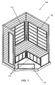
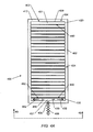
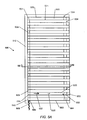
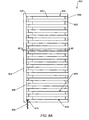
- FIG. 1 is a perspective view of an infrared sauna 100 according to an embodiment of the invention.
- the sauna 100 includes a number of infrared heating panels 110 that, when powered, generate infrared radiation for warming a person within the sauna 100.
- the sauna 100 depicted in FIG. 1 is just one example of many possible designs and that it is contemplated that some embodiments of the invention may include a wide variety of sauna designs.
- the infrared heating panels 110 may be provided with a number of physical dimensions and configurations to accommodate the overall sauna design and provide a desired heating environment.
- the sauna 100 shown in FIG. 1 includes a number of differently sized heating panels 110 positioned on the walls, floor, and bench of the sauna 100.
- a heating panel may be useful by itself as a heat generating device.
- a heating panel may be useful by itself as a heat generating device.
- applications of a heating panel are not so limited and that heating panels in accordance with embodiments of the invention may be useful for many applications in a variety of environments in which a device is desired for producing radiant heat with infrared EM radiation.
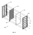
- the heating panel 200 includes multiple heating elements 204 arranged on the substrate 202 in a row, though it is contemplated that in some cases a heating panel may only include a single heating element or many more heating elements than are shown in the figures.
- Each heating element 204 includes a first segment 220 and a second segment 222 attached to the substrate 202.
- the first segment 220 of each heating element is formed from a strip of an electrically resistive (e.g., semi-conducting) material adapted to emit infrared radiation in response to a current flowing through the material.
- the first power bus 208 may provide the first segments 220 with a current at a positive voltage (e.g., 120 VAC), while the second power bus 210 connects the second segments 222 to AC ground.
- the power buses 208, 210 extend across opposite surfaces of the substrate 202 in a parallel configuration at one end of the heating elements, transverse to the lengthwise direction of the heating element segments.
- the multiple heating elements 204 are thus electrically coupled together in a parallel electrical configuration across the two power buses 208, 210.
- the first segment 220 and the second segment 222 are elongated and stretch across the substrate 202 in a parallel arrangement with the second segment opposite the substrate from the first segment.
- the term parallel is used herein to describe a layout in which the first and the second segments for a given heating element extend along a common plane intersecting the segments perpendicular to the substrate. In some cases machine or method tolerances and/or practical manufacturing limitations may produce less than mathematically true or exact parallel alignment, but arrangements with these types of variations are still considered parallel for purposes of this disclosure. In addition, in some cases small variations from a true parallel arrangement may be acceptable depending upon the resulting functionality and desired performance criteria.
- a current 230 flows through the heating element 204 between a first connection point 231 at the first power bus 208 to a second connection point 233 at the second power bus 210.
- the current 230 flows through the first segment 220, it flows in a first direction 232 relative to the substrate 202 that is opposite a second direction 234 that it flows in the second segment 222. Because the same current 230 flows through both the first segment 220 and the second segment 222 of a particular heating element 204, the opposite polarity EM fields that are generated by the segments have the same or substantially the same magnitudes, leading to improved field canceling and low frequency EM field reduction.
- low frequency is used generically herein to generally refer to EM radiation emanating from a heating panel at frequencies below the infrared radiation generated by the heating panel. Such frequencies may include, for example, very low frequencies (3-30 kHz), ultralow frequencies (300-3 kHz), super low frequencies (30-300 Hz), and/or extremely low frequencies (3-30 Hz), among other higher and lower ranges below infrared frequencies.
- powering a conventional infrared heating panel with an alternating current can generate undesired low frequency or extremely low frequency EM radiation.
- a 120VAC, 60 Hz power input may lead to undesirably high levels of EM radiation at about 60 Hz.
- the heating panel 200 advantageously simplifies the system complexity compared to prior heating panels, while also delivering sufficient infrared heat and sufficiently reduced low frequency EM radiation levels, e.g., at 60 Hz.
- the parallel arrangement of the heating element segments 220, 222 on the substrate 202 reduces low frequency EM radiation by setting up the single current 230 flowing through both segments as determined by the overall load characteristics for the entire heating element.
- the current 230 tends to generate a first EM field as it passes through the first segment 220, with a polarity opposite to a second EM field that it generates as it passes through the second segment 222.
- the first and the second EM fields tend to counteract each other to reduce or substantially cancel the low frequency EM field levels emitted by a single heating element 204.
- the opposite polarity EM fields generated by the single current 230 have the same or substantially the same magnitudes, leading to improved field canceling and low frequency EM field reduction.
- an opposite and parallel arrangement of the first and the second power buses 208, 210 can provide similar benefits.
- the inventors have found that certain measured low frequency magnetic field intensities are maintained at or below a 1.0 milligauss level at two inches from the panel across substantially the entire area of the heating elements 204. In further testing, the inventors found that certain low frequency magnetic field intensities are at or below a 1.5 milligauss level at two inches from the panel across substantially the entire length and width of the first and the second power buses 208, 210, in addition to the solder connection points between the power buses and the power conductors 206.
- misalignment of the first and the second segments 220, 222 of a particular heating element 204 from a parallel arrangement on opposite sides of the substrate 202 can reduce cancellation of undesired EM fields.
- it can be advantageous to precisely overlap the segments to the extent practical in order to maximize EM field cancellation.
- the inventors have found that in some cases the configuration of the first and the second heating element segments 220, 222 has less of an effect upon the magnitude of certain low frequency EM radiation when compared with the effect caused by the first and the second power buses 208, 210. Accordingly, it may be more acceptable in some cases to allow greater amounts of misalignment between the heating element segments than the power buses, though numerous variations are of course possible.
- cancellation of undesired EM fields can be improved by providing the first segment 220 and/or the second segment 222 of a particular heating element 204 with matching dimensions.
- the width of the second segment 222 is substantially equal to the width of the first segment 220.
- the widths of the first and the second segments are substantially equal, and the segments are attached opposite each other on the substrate such that both segments are centered on and extend along a plane perpendicular to the substrate. This arrangement can provide a high degree of low frequency EM field cancellation, though it is not strictly required.
- the substrate 202 may be extremely thin in order to reduce the gap between the segments while also maintaining electrical isolation along the lengths of the segments. As just a single example, in some cases the substrate may only be about 0.2 mm thick. Of course other dimensions are also contemplated.
- a resistive thin film may be formed upon the substrate in any suitable manner, including by thin film deposition or etching.
- Another method of forming the thin film includes screen printing using a carbon based ink, such as a colloidal graphite ink.
- a carbon-based material is described in U.S. Patent Application Serial No. 12/573,882 , the entire content of which is hereby incorporated by reference.
- U.S. Patent No. 4,485,297 illustrates additional examples of resistive/semi-conductive materials, and its entire content is hereby incorporated by reference as well.
- the second segments 222 are each formed from a flat strip of an electrically conductive material attached to the second surface 214 of the substrate 202 opposite and parallel to a corresponding first segment 220.
- the conductive material is provided in the form of a flat, metal strip, such as a strip of copper or other suitable metal pressed into and/or adhered to the second surface 214 of the substrate.
- the conductive material is a particulate material deposited upon the substrate.
- a conductive material may be screen printed upon the substrate to provide the second segments. In this case the same or similar screen printing patterns can be used for the top and bottom surfaces of the substrate, therefore minimizing manufacturing complexity and variations.
- the second segments need not be a purely conductive material, but in some cases may instead be formed from a more resistive or semi-conductive material. In certain cases the second segments 222 may be formed from the same resistive material used to form the first segments 220, which can simplify material requirements.
- the second segments 222 are shown in dashed lines, indicating they are placed on the second surface 214 on the other side of the substrate 202 from the first segments 220.
- FIG. 2D shows the first segments 220 in dashed lines, indicating they are placed on the first surface 212 or other side of the substrate 202 from the second segments 222.
- FIGS. 2A and 2D schematically illustrate the first segments 220 as being slightly wider than the second segments 222 to allow discernment of the different segments in the views. In some cases the first segment 220 may have a greater width than the second segment 222 (or vice versa).
- the second segment 222 of electrically conductive material may be formed slightly narrower than the first segment of electrically resistive material.
- the first and the second segments 220, 222 are formed with consistently identical, or substantially identical, widths and are placed on opposite surfaces of the substrate in an overlapping, parallel configuration. It should be appreciated that a number of configurations are contemplated for the widths of the segments. The choice of any particular configuration will depend upon the desired EM reduction characteristics.
- voids 205 are formed in the panel substrate 202 in each location where a connection between a first segment 220 and a second segment 222 is planned.
- the voids 205 can be created in any suitable manner (e.g., drilled, cut, preformed, etc.). In some cases the voids 205 are substantially the same width as the heating element segments, though this is not a requirement in all cases.
- the second segments 222 of each heating element are applied/attached to the second surface 214 of the substrate, with each of the second segments 222 overlapping a void 205 in the substrate.
- the first heating element segments 220 are attached to the first surface of the substrate.
- a resistive material e.g., a carbon-based thin film
- the screen print also overlaps and fills the voids 205 extending through the thickness of the substrate 202 and making contact with each respective second segment 222 attached to the second surface 214.
- both the first and the second segments 220, 222 are screen printed, each filling a portion of the void 205.
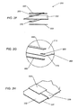
- the segments may instead be coupled together about an edge 227 of the substrate 202.
- a strip 229 of conductive material e.g., a metal foil strip or band
- the electrical coupling between the strip 229 and the segments can be formed in any suitable manner, including soldering or adhering the strip to the substrate and then placing the first and the second segments over top of the strip. Further examples of such connections are discussed with respect to FIGS. 5-8 .
- the first power bus 208 is attached to and extends across the first surface 212 of the substrate in a perpendicular orientation with the first segments of the heating elements.
- the first bus 208 electrically couples to the end of each first segment 220 (i.e., at junction 231) that is opposite the end of the first segment coupled to a respective second segment 222 (i.e., at junction 225).
- the second power bus 210 is attached to and extends across the second surface 214 of the substrate in a perpendicular orientation with the second segments of the heating elements.
- the first and the second power buses 208, 210 may be formed from any suitable electrically conductive material, such as a metal (e.g., copper or another other metal or alloy).
- a metal e.g., copper or another other metal or alloy
- the first and the second power buses 208, 210 are each formed from a flat metal strip that is secured to the substrate 202 during a laminating process similar to construction of a printed circuit board.
- metal strips may be attached in other ways, including for example, with an adhesive, welding, or another mechanism.
- the first and/or the second power buses may alternatively be formed with a different process such as screen printing, etching, deposition, or another type of formation methods.
- the heating panel 200 may be conveniently produced by providing the electrically insulative substrate 202 and then attaching the first power bus 208 to the substrate (e.g., through mechanical attachment of a metal strip or screen printing a conductive particulate material). Multiple carbon traces can then be printed on the first surface 212 of the substrate to provide multiple first segments 220 overlapping and electrically connected to the first power bus. The substrate 202 is then turned over and the second power bus 210 and multiple second segments 222 are attached to the second surface 214 in a similar manner.
- the first and the second power buses 208, 210 can be coupled to the first segments 220 and the second segments 222 of the heating elements 204 in any suitable manner.
- the power buses and the heating element segments are sandwiched together about the substrate 202 in a laminating process.
- the first power bus 208 is placed (e.g., deposited, formed, attached, etc.) on the first surface 212 of the substrate 202
- the second power bus 210 is placed on the second surface 214 of the substrate 202.
- the panel 200 is formed as a laminate having multiple layers proximate to the electrical connections between the heating element and the power buses.
- the laminate includes in order from top down shown in FIG. 2C , the first segment 220, the first power bus 208, the substrate 202, the second power bus 210, and the second segment 222.
- the laminate includes in order from top down shown in FIG. 2C , the first segment 220, the first power bus 208, the substrate 202, the second power bus 210, and the second segment 222.
- an outer insulative layer may be placed adjacent the first segment 220 and also adjacent the second segment 222 to electrically insulate the entire panel 200.
- the thermal shielding layer 310 also acts as a ground plane to shield a sauna user from electric fields generated by the heating panel.
- the thermal shielding layer 310 is formed from a conductive fabric and then connected by wire to ground potential through, e.g., the power conductors, the panel frame, a conduit, or another suitable surface or component at ground potential.
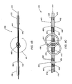
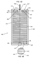
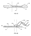
- FIGS. 4A and 4D are side views of opposite surfaces of an infrared heating panel 400 according to some embodiments of the invention.
- FIG. 4B is an end view of the infrared heating panel 400 from along line 4B-4B
- FIG. 4C is an enlarged end view of portion 4C shown in FIG. 4B
- FIG. 4E is an enlarged view of portion 4E shown in FIG. 4D
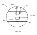
- FIG. 4F is an enlarged view of portion 4F shown in FIG. 4D .
- the heating panel 400 generally includes a planar substrate 402 with multiple infrared heating elements 404 carried by the substrate 402.
- the heating panel 400 includes a twisted pair of power conductors 406 that can be connected to an electrical power supply to energize the panel 400.
- the heating elements 404 are electrically coupled to the power conductors 406 in this case with a first power bus 408 and a second power bus 410, which serve to distribute the electrical power to the multiple heating elements 404.
- the substrate 402 has a generally planar configuration with a first surface 412 and a second surface 414, and is constructed from an electrically insulative material (e.g., an FR-4 circuit board) for mounting or attaching the heating elements 404.
- Each heating element 404 includes a first segment 420 and a second segment 422 that are electrically coupled together.
- the first and the second segments 420, 422 are elongated and stretch across the substrate 402 in a parallel and spaced apart configuration, and are electrically coupled together at both ends of the segments.
- the multiple heating elements 404 are arranged on the substrate 402 in a row, with the individual segments of the heating elements in a parallel configuration.
- first segment 420 of each heating element 404 is attached to the first surface 412 of the substrate 402 and the second segment 422 of each heating element 404 is attached to the second surface 414 of the substrate 402.
- the second segment 422 is attached to the substrate's second surface 414 opposite the substrate from and in a parallel arrangement with the first segment 420 on the substrate's first surface 412, in order to provide a low frequency EM field reducing/canceling configuration.
- the heating element segments are electrically coupled to the power conductors 406 via the first power bus 408 and the second power bus 410.
- the power buses 408, 410 extend across opposite surfaces of the substrate 402 perpendicular to the lengthwise direction of the first and the second segments.
- the second power bus 410 is attached to the second surface 414 of the substrate opposite from and in a parallel arrangement with the first power bus 408, which is attached to the first surface 412 of the substrate.
- the power buses 408, 410 connect to the first and the second segments 420, 422 of the heating elements at a point between the ends of the heating element, rather than at one end as in FIGS. 2A-2E .
- the first power bus 408 is connected to the first segments 422 at approximately the midpoint of the first segments
- the second power bus 410 is connected to the second segments 422 at approximately the midpoint of the second segments.
- the first and the second power buses 408, 410 create multiple parallel connections and current paths through separate portions of the first and the second segments between the power buses.
- the first segments 420 of the heating elements 404 are each formed from a strip of an electrically resistive thin film attached to the first surface 412 of the substrate 402 and adapted to emit infrared radiation in response to a current flow.
- the first segments 420 are formed from a carbon-based thin film, such as is described with respect to FIGS. 2A-2E .
- the second segments 422 are each formed from a strip of an electrically conductive material (e.g., a metal) attached to the second surface 414 of the substrate 402 opposite and parallel to a corresponding first segment 420.
- Other materials, including printed and/or resistive materials are also contemplated for the second segments 422.
- the second segments 422 are shown in dashed lines, indicating they are placed on the second surface 414 or other side of the substrate 402 from the first segments 420.
- FIG. 4E schematically illustrates the first segments 420 as being slightly wider than the second segments 422 to allow discernment of the different segments in the views.
- the first and the second segments 420,422 are formed with consistently identical, or substantially identical, widths and are placed on opposite surfaces of the substrate in an overlapping, parallel configuration.
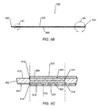
- the heating panel 500 includes a substrate 502 that carries multiple heating elements 504 positioned in a row across the panel.
- Each heating element 504 includes a first segment 520 attached to a first surface 512 of the substrate and a second segment 522 attached to a second surface 514 of the substrate 502.
- the first and second segments 520, 522 are electrically connected together in series at one end of the segments, in this embodiment about an edge of the substrate 502.
- the segments are electrically coupled to power conductors 506 via a first power bus 508 and a second power bus 510. Similar to the embodiment in FIGS. 2A-2E , the power buses 508, 510 extend across opposite surfaces of the substrate 502 in a parallel configuration at one end of the heating elements.
- the widths of the first and the second power buses are substantially equal, and the buses are attached opposite each other on the substrate 502 such that corresponding first edges 516, 518 of the buses are substantially aligned and corresponding second edges 517, 519 are substantially aligned (as shown by the dashed lines in FIG. 5C ).
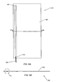
- FIGS. 6A-6D are simplified views of the heating panel 500 without the heating elements 504, providing a cleaner view of the opposite and parallel arrangement of the power buses.
- This arrangement of the power buses can provide a high degree of low frequency EM field cancellation, though it is not strictly required in all cases.
- the first power bus and the second power bus could potentially be offset a small amount, or could have different widths and/or be offset from an exact mirrored placement upon opposing surfaces of the substrate depending upon the level of EM field cancellation desired.
- the second segments 522 are each formed from a flat strip of an electrically conductive material attached to the second surface 514 of the substrate 502 opposite and parallel to a corresponding first segment 520.
- the conductive material is provided in the form of a flat, metal strip, such as a strip of copper or other suitable metal pressed into and/or adhered to the second surface 514 of the substrate.
- the conductive material is a particulate material deposited upon the substrate.
- a conductive material may be screen printed upon the substrate to provide the second segments. In this case the same or similar screen printing patterns can be used for the top and bottom surfaces of the substrate, therefore minimizing manufacturing complexity and variations.
- the second segments need not be a purely conductive material, but in some cases may instead be formed from a more resistive or semi-conductive material. In certain cases the second segments 522 may be formed from the same resistive material used to form the first segments 520, which can simplify material requirements.
- composition and application of heating element segments can vary.
- Table 1 below provides a summary of four possible combinations of materials.
- Table 1 Segment Material Application First Segment Electrically Resistive Material Printed Second Segment Electrically Conductive Material Metal Strip First Segment Electrically Resistive Material Printed Second Segment Electrically Conductive Material Printed First Segment Electrically Resistive Material Applied Strip Second Segment Electrically Conductive Material Metal Strip First Segment Electrically Resistive Material Printed Second Segment Electrically Resistive Material Printed
- Table 1 provides a summary of four possible combinations of materials.
- Table 1 Segment Material Application First Segment Electrically Resistive Material Printed Second Segment Electrically Conductive Material Metal Strip First Segment Electrically Resistive Material Printed Second Segment Electrically Conductive Material Printed First Segment Electrically Resistive Material Printed Second Segment Electrically Resistive Material Printed
- Other combinations of materials in addition to those listed above are also possible.
- the heating element second segment 522 includes a thin, flat strip of copper that extends across the second surface 514 of the substrate 502.
- the second segment 522 is placed adjacent the second power bus 510, which is also a thin flat strip of copper extending across the second substrate surface 514 perpendicular to the second segment 522.
- the second segment 522 and second power bus 510 are separate components, placed adjacent one other and then held together with a laminating process.
- the second power bus 510 and some or all of the second segments 522 may be integrally formed in a single layer.
- the power bus and segments may be stamped out of a single metal sheet.
- both the second power bus 510 and the second segments 522 are printed upon the substrate in a single, integral layer using the same material.
- the heating panel would include a number of layers, including, in order, the first segment 520, the first power bus 508, the substrate 502, and the combined second power bus/second segment layer.
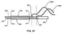
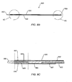
- FIG. 5D is an enlarged cross-sectional view of the end of the infrared heating panel 500 shown in FIGS. 5A-5C .
- the first segment and the second segment of a given heating element are electrically connected in series at one end of the segments.
- the segments can be connected together in a variety of manners, including through the panel substrate or around an edge of the substrate.
- a connecting strip 550 is folded about the edge of the substrate 501 to connect the first segment 520 with the second segment 522.
- the connecting strip is preferably a flat metal (e.g., copper) strip with a width similar to the widths of the first and second segments, though other materials may be used.
- the connecting strip 550 connects to the first segment at a junction 552, but is integral to the second segment 522.
- the connecting strip 550 may be separate from the first and the second segments 520, 522.
- the separate connecting strip 550 is folded about the edge of the substrate 502 opposite from the power buses 508, 510.
- the connecting strip 550 makes contact with the heating element first segment 520 at a first junction 552, and with the second segment 522 at a second junction 554.
- the connecting strip 550 may be pressed into the substrate 502 and somewhat flush with the substrate surfaces as a result of making the panel 500 with a printed circuit board fabrication process.
- the second segments may instead be formed from a conductive (or alternately semi-conductive) particulate matter deposited on the second surface 514 of the substrate over the second power bus 510 and the connecting strip 550.
- the second segments 522 may be applied using a screen printing process. The inventors have found that in some cases forming the bus/segment junction 533 and the connecting strip/segment junction 554 in this manner provides a superior connection between the components in terms of connection clarity and uniformity when compared with connections between adjacent metal strips.
- epoxy or resin can squeeze in between the metal strips, which contaminates the junction and leads to current density imperfections that can affect the level of EM noise produced.
- depositing the segments upon the substrate and power buses/connecting strips using a screen printing process can provide a substantially uniform interface and uniform current densities.
- the inventors have found that in some cases the configuration of the first and the second power buses has an increased effect upon the magnitude of certain low frequency EM radiation when compared with the effect caused by individual heating elements 504.
- the first and the second power buses 508, 510 are preferably configured to reduce the magnitude of unwanted low frequency EM fields emanating from the heating panel 500.
- connections between the first and the second power buses 508, 510 and the power conductors 506 are configured to reduce undesirable low frequency EM radiation generated by the connections.
- a first power conductor 506A e.g., a 120 VAC line
- a second power conductor 506B e.g., a 0 VAC line
- the second power conductor 506B may connect to the second power bus 510 through the substrate as illustrated in FIG.
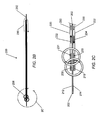
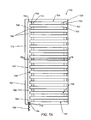
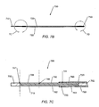
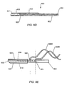
- FIG. 7A is a side surface view of an infrared heating panel 700 according to another embodiment of the invention.
- FIG. 7B is a cross-sectional view of the infrared heating panel 700 of FIG. 7A along line 7B-7B.
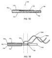
- FIG. 7C is an enlarged view of one end of the infrared heating panel 700 shown in FIG. 7B .
- FIG. 7D is an enlarged view of another end of the infrared heating panel 700 shown in FIG. 7B .
- FIG. 7E is an enlarged side end view of a connection portion of the infrared heating panel 700 of FIG. 7A .
- the heating panel 700 is similar in many respects to the heating panel 500 discussed with respect to FIGS. 5A-5F , and portions of that discussion are also applicable to the embodiment shown in FIGS. 7A-7E .
- the heating panel 700 includes a substrate 702 that carries multiple heating elements 704 positioned in a row across the panel.
- Each heating element 704 includes a first segment 720 attached to a first surface 712 of the substrate and a second segment 722 attached to a second surface 714 of the substrate 702.
- the first and second segments 720, 722 are electrically connected together in series at one end of the segments, in this embodiment about an edge of the substrate 702.
- the segments are electrically coupled to power conductors 706 via a first power bus 708 and a second power bus 710.
- the power buses 708, 710 extend across opposite surfaces of the substrate 702 in a parallel configuration at one end of the heating elements.
- the first power bus 708 extends across and is attached to the first surface 712 of the substrate.
- the second power bus 710 is attached to the second surface 714 of the substrate 702, opposite from and in a parallel arrangement with the first power bus 708.
- the first and the second power buses 508, 510 may be any suitable electrically conductive material, such as those described elsewhere herein, and can be attached to the substrate in any suitable manner (e.g., printed or applied).
- each of the first and the second power buses 708, 710 is an elongated flat strip of material having opposing ends and opposing sides, as well as multiple integral tabs extending out along one of the sides.
- the first power bus 708 includes opposing first and second ends 743, 745, and opposing first and second sides 747, 749.
- the first power bus 708 also includes multiple tabs 760 extending out from the second side 749 of the bus, in the direction of the heating elements 704.
- the heating elements 704 extend across and are attached to the substrate in a perpendicular orientation to the power buses in a similar fashion to other embodiments described herein.
- first and the second segments 720, 722 of the heating elements extend across the first and second surfaces of the substrate toward the power buses, but do not contact the power bus main flat strip. Instead, each of the first segments 720 attaches to one of the tabs 760 extending out from the first power bus at junction 731, and each of the second segments 722 attaches to one of the tabs 762 extending out from the second power bus at junction 733.
- the power buses 808, 810 extend across opposite surfaces of the substrate 802 in a parallel configuration at one end of the heating elements.
- the first power bus 808 extends across and is attached to the first surface 812 of the substrate.
- the second power bus 810 is attached to the second surface 814 of the substrate 802, opposite from and in a parallel arrangement with the first power bus 808.
- the first and the second power buses 508, 510 may be any suitable electrically conductive material, such as those described elsewhere herein, and can be attached to the substrate in any suitable manner (e.g., printed or applied).
- a particulate resistive material to create the bus/segment junction 831 is thought to provide a superior connection between the first power bus and each of the first segments 820 in terms of connection clarity and uniformity when compared with connections between adjacent metal strips (see, e.g., the junction 533 between the second power bus 510 and the second segments 522 in FIG. 5C ).
- the current profile surrounding the respective junctions with the first and the second power buses will vary, thus tending to generate undesirable low frequency EM emissions due to the mismatch in current densities in the first and the second power buses.
- the use of multiple bridging strips 890 to connect each of the second segments 822 to the second power bus 810 can help provide more uniform current profiles in the first and second power buses, which can also reduce undesirable EM emissions generated at the bus-segment junctions.
- the bridging strips 890 are preferably made from the same material as the heating element first segments 820, which is this case is a printed electrically resistive material. As shown in FIG. 8C , the bridging strip 890 connects to the second power bus 810 at a first junction 835 and to the second segment 822 at a second junction 837.
- the bridging strip is formed from the same material as the first segment 820, the first junction 835 tends to mirror the behavior of the junction 831 between the first segment and the first power bus, thus leading to increased EM field cancellation at the bus where current levels tend to be higher than in each individual heating element.
- Some embodiments of the invention provide methods for reducing electromagnetic emissions in an infrared sauna.
- a method includes providing one of the infrared heating panels described above, mounting it in an infrared sauna, and energizing the panel to generate infrared radiation to warm a sauna user, while also reducing, canceling, or substantially canceling, certain low frequency and/or extremely low frequency EM fields.
- a method for reducing electromagnetic emissions in an infrared sauna includes providing one or more infrared heating panels.
- Each heating panel includes an electrically insulative planar substrate and at least one infrared heating element.
- the heating element includes an elongated first segment attached to a first surface of the substrate and an elongated second segment attached to a second surface of the substrate.
- the first and second segments are electrically coupled together to provide a continuous conduction path.
- the method also includes producing a first current through the first segment of the heating element to generate infrared radiation for heating a human in the infrared sauna.
- the first current flows through the first segment in a first direction relative to the substrate, thus generating a corresponding first electromagnetic field at frequencies below the infrared radiation.
- the method also includes flowing the first current through the second segment of the heating element in a second direction relative to the substrate opposite the first direction in order to generate a corresponding second electromagnetic field that counteracts or cancels the first electromagnetic field.
Landscapes
- Engineering & Computer Science (AREA)
- Health & Medical Sciences (AREA)
- Mechanical Engineering (AREA)
- Public Health (AREA)
- General Engineering & Computer Science (AREA)
- Combustion & Propulsion (AREA)
- Chemical & Material Sciences (AREA)
- Thermal Sciences (AREA)
- Physics & Mathematics (AREA)
- Veterinary Medicine (AREA)
- General Health & Medical Sciences (AREA)
- Animal Behavior & Ethology (AREA)
- Life Sciences & Earth Sciences (AREA)
- Epidemiology (AREA)
- Rehabilitation Therapy (AREA)
- Pain & Pain Management (AREA)
- Physical Education & Sports Medicine (AREA)
- Resistance Heating (AREA)
- Devices For Medical Bathing And Washing (AREA)
- Radiation-Therapy Devices (AREA)
Claims (15)
- Infrarotheizungsplatte (110, 200, 400, 500, 700, 800), umfassend:ein elektrisch isolierendes ebenes Substrat (202, 402, 502, 702, 802), das eine erste Oberfläche (212, 412, 512, 712, 812) und eine gegenüberliegende zweite Oberfläche (214, 414, 514, 714, 814) aufweist; undein oder mehrere Infrarotheizelemente (204, 404, 504, 704, 804), die von dem Substrat getragen werden, wobei jedes des einen oder der mehreren Heizelemente umfasst ein längliches erstes Segment (220, 420, 520, 720, 820), das an der ersten Oberfläche des Substrats befestigt ist, undein längliches zweites Segment (222, 422, 522, 722, 822), das an der zweiten Oberfläche des Substrats gegenüber dem ersten Segment befestigt ist,wobei mindestens das erste Segment ein Band aus einem elektrisch widerstandsfähigen Material umfasst, das geeignet ist, als Reaktion auf einen Strom eine Infrarotstrahlung abzugeben,dadurch gekennzeichnet, dassdas zweite Segment mit dem ersten Segment elektrisch in Reihe geschaltet ist und sich in einer parallelen Anordnung zu dem ersten Segment befindet, sodass ein erster durch das Heizelement fließender Strom in einer ersten Richtung relativ zum Substrat durch das erste Segment fließt und in einer zweiten Richtung entgegengesetzt zur ersten Richtung durch das zweite Segment fließt,wobei das Band aus dem elektrisch widerstandsfähigen Material geeignet ist, als Reaktion auf den ersten Strom eine Infrarotstrahlung abzugeben.
- Infrarotheizungsplatte nach Anspruch 1, wobei das erste Segment ein flaches Band umfasst, das eine Länge und eine Breite aufweist und das zweite Segment ein flaches Band umfasst, das eine Länge und eine Breite aufweist, die im Wesentlichen gleich der Breite des ersten Segments sind.
- Infrarotheizungsplatte nach Anspruch 1, wobei das zweite Segment ein flaches Band aus einem Metall aufweist.
- Infrarotheizungsplatte nach Anspruch 1, wobei mindestens eines des ersten Segments und des zweiten Segments auf das Substrat gedruckt ist.
- Infrarotheizungsplatte nach Anspruch 1, die außerdem eine Vielzahl der Infrarotheizelemente, die über das Substrat verteilt in einer Reihe angeordnet sind, einen ersten Stromversorgungsbus, der auf der ersten Oberfläche des Substrats befestigt ist und elektrisch mit jedem der ersten Segmente der Heizelemente verbunden ist, und einen zweiten Stromversorgungsbus, der auf der zweiten Oberfläche des Substrats gegenüber und in einer parallelen Anordnung zu dem ersten Stromversorgungsbus befestigt ist, umfasst, wobei der zweite Stromversorgungsbus elektrisch mit jedem der zweiten Segmente der Heizelemente verbunden ist.
- Infrarotheizungsplatte nach Anspruch 5, wobei der erste Stromversorgungsbus ein flaches Band umfasst, das eine Länge und eine Breite aufweist, und wobei jedes der ersten Segmente der Heizelemente die gesamte Breite des ersten Stromversorgungsbusses überlappt.
- Infrarotheizungsplatte nach Anspruch 5, wobei der erste Stromversorgungsbus ein flaches Band umfasst, das eine Länge und eine Breite aufweist, und der zweite Stromversorgungsbus ein flaches Band umfasst, das eine Länge und eine Breite aufweist, die im Wesentlichen gleich der Breite des ersten Stromversorgungsbusses sind.
- Infrarotheizungsplatte nach Anspruch 5, wobei mindestens einer des ersten Stromversorgungsbusses und des zweiten Stromversorgungsbusses auf das Substrat gedruckt ist.
- Infrarotheizungsplatte nach Anspruch 5, wobei der zweite Stromversorgungsbus und die zweiten Segmente der Heizelemente vollständig miteinander verbunden sind und flache Bänder aus einem Metall umfassen.
- Infrarotheizungsplatte nach Anspruch 5, wobei die zweiten Segmente der Heizelemente sich über die zweite Oberfläche des Substrats bis zum zweiten Stromversorgungsbus erstrecken, ohne ihn zu berühren, und außerdem eine Vielzahl von überbrückenden Bändern umfassen, wobei jedes überbrückende Band eines der zweiten Segmente mit dem zweiten Stromversorgungsbus verbindet.
- Infrarotheizungsplatte nach Anspruch 5, wobei die Platte als ein Laminat ausgebildet ist, wobei das Laminat in der Nähe der elektrischen Verbindung von jedem ersten Segment mit dem ersten Spannungsversorgungsbus und von jedem gegenüberliegenden und parallelen zweiten Segment mit dem zweiten Spannungsversorgungsbus eine Vielzahl von Schichten umfasst, die in folgender Reihenfolge das erste Segment, den ersten Spannungsversorgungsbus, das Substrat, den zweiten Stromversorgungsbus und das zweite Segment aufweisen.
- Infrarotheizungsplatte nach Anspruch 1, die außerdem eine Vielzahl von Lücken in dem Substrat umfasst, wobei jedes der ersten Segmente durch eine der Lücken mit einem entsprechenden zweiten Segment elektrisch verbunden ist.
- Infrarotheizungsplattenbaugruppe (300), umfassend: die Infrarotheizungsplatte nach Anspruch 1, ein rückseitiges Rahmenelement (304) und ein vorderseitiges Rahmenelement (306), welche das Substrat und die von dem Substrat getragenen ein oder mehrere Heizelemente einschließt, eine elektrische Verbindung (206) zum Verbinden des einen oder der mehreren Heizelemente mit einer Wechselstromquelle, und eine Wärmeschutzschicht (310), wobei das vorderseitige Rahmenelement eine oder mehrere Öffnungen (312) aufweist und die Wärmeschutzschicht zwischen dem einen oder den mehreren Infrarotheizelementen und der einen oder den mehreren Öffnungen angebracht ist.
- Infrarotsauna (100), die eine Vielzahl von Infrarotheizungsplatten nach Anspruch 1 umfasst.
- Verfahren zum Verringern elektromagnetischer Strahlungen bei einer Infrarotsauna (100), umfassend:Bereitstellen eines oder mehrerer Infrarotheizungsplatten (110, 200, 400, 500, 700, 800), wobei jede Heizungsplatte ein elektrisch isolierendes ebenes Substrat (202, 402, 502, 702, 802) und mindestens ein Infrarotheizelement (204, 404, 504, 704, 804) umfasst, das ein längliches erstes Segment (220, 420, 520, 720, 820) umfasst, das an einer ersten Oberfläche (212, 412, 512, 712, 812) des Substrats befestigt ist;Herstellen eines ersten Stroms durch das erste Segment des mindestens einen Infrarotheizelements, um eine Infrarotstrahlung zum Wärmen eines Menschen in der Infrarotsauna (100) zu erzeugen, wobei der erste Strom in einer ersten Richtung relativ zum Substrat durch das erste Segment fließt und ein entsprechendes erstes elektromagnetisches Feld mit Frequenzen unterhalb der Infrarotstrahlung erzeugt;dadurch gekennzeichnet, dass das Infrarotheizelement ein längliches zweites Segment (222, 422, 522, 722, 822) umfasst, das an einer zweiten Oberfläche (214, 414, 514, 714, 814) des Substrats befestigt ist, wobei die ersten und die zweiten Segmente elektrisch miteinander verbunden sind, um einen kontinuierlichen Leitungspfad bereitzustellen, und durch den zusätzlichen Schritt einesLeitens des ersten Stroms durch das zweite Segment des mindestens einen Infrarotheizelements in einer zweiten Richtung relativ zu dem Substrat entgegengesetzt zur ersten Richtung, wobei der erste Strom ein entsprechendes zweites elektromagnetisches Feld erzeugt, das dem ersten elektromagnetischen Feld entgegenwirkt.
Applications Claiming Priority (3)
| Application Number | Priority Date | Filing Date | Title |
|---|---|---|---|
| US33735710P | 2010-02-02 | 2010-02-02 | |
| US12/966,221 US8692168B2 (en) | 2010-02-02 | 2010-12-13 | Infrared heating panels, systems and methods |
| PCT/US2011/022215 WO2011097086A2 (en) | 2010-02-02 | 2011-01-24 | Infrared heating panels, systems and methods |
Publications (2)
| Publication Number | Publication Date |
|---|---|
| EP2531775A2 EP2531775A2 (de) | 2012-12-12 |
| EP2531775B1 true EP2531775B1 (de) | 2015-03-11 |
Family
ID=44356036
Family Applications (1)
| Application Number | Title | Priority Date | Filing Date |
|---|---|---|---|
| EP11702346.5A Active EP2531775B1 (de) | 2010-02-02 | 2011-01-24 | Infrarot-heizung platten, systeme und verfahren |
Country Status (3)
| Country | Link |
|---|---|
| US (1) | US8692168B2 (de) |
| EP (1) | EP2531775B1 (de) |
| WO (1) | WO2011097086A2 (de) |
Families Citing this family (24)
| Publication number | Priority date | Publication date | Assignee | Title |
|---|---|---|---|---|
| US9326498B2 (en) | 2010-09-14 | 2016-05-03 | JAB Distributors, LLC | Heatable enclosure for pest eradication |
| US11202346B2 (en) | 2011-03-25 | 2021-12-14 | Sauna Works Inc. | Electromagnetic wave reducing heaters and devices and saunas |
| US11896547B2 (en) | 2011-03-25 | 2024-02-13 | Sauna Works Inc. | Low EMF halogen tube heater |
| US9844100B2 (en) | 2011-03-25 | 2017-12-12 | Raleigh C. Duncan | Electromagnetic wave reducing heater |
| KR101553785B1 (ko) * | 2011-06-10 | 2015-09-16 | 쌩-고벵 글래스 프랑스 | 안전 기능이 있는 발열 복합 창판 |
| DK2587169T3 (da) | 2011-10-31 | 2019-10-14 | Tylohelo Inc | Elektrisk drevet varmepanel og fremgangsmåde for tilvejebringelse af en strøm-tilslutning |
| US8689481B2 (en) * | 2011-12-12 | 2014-04-08 | Pab Two, Llc | Integration of surface heating to an enclosure |
| US20130319998A1 (en) * | 2012-05-31 | 2013-12-05 | Steven John Benda | Sauna Infrared Heating Panel Systems and Methods |
| US9629777B2 (en) * | 2012-06-30 | 2017-04-25 | Hi-Q Holdings Llc | Exercise sauna having far infrared heating elements and configurable seating |
| US10278892B2 (en) * | 2012-10-31 | 2019-05-07 | Tylohelo Inc. | Printed shield with grounded matrix and pass through solder point systems and methods |
| US9393176B2 (en) | 2013-02-01 | 2016-07-19 | Tylohelo, Inc. | Infrared heating panels with non-linear heat distribution |
| DE102013214548B4 (de) * | 2013-07-25 | 2022-08-11 | Bayerische Motoren Werke Aktiengesellschaft | Fahrzeug mit einer elektrischen Heizeinrichtung |
| ES2469769B1 (es) * | 2013-11-19 | 2015-04-29 | Iredheat Systems, S.L | Panel radiante por infrarrojos mejorado |
| US9770386B2 (en) * | 2014-08-23 | 2017-09-26 | High Tech Health International Inc. | Sauna heating apparatus and methods |
| US10765597B2 (en) * | 2014-08-23 | 2020-09-08 | High Tech Health International, Inc. | Sauna heating apparatus and methods |
| US10616955B1 (en) * | 2016-02-23 | 2020-04-07 | Sunlighten, Inc. | Personal sauna unit with integrated chromotherapy lighting |
| JP2020515021A (ja) | 2017-01-06 | 2020-05-21 | レボリューション・クッキング・エルエルシー | 調理機器のための加熱要素 |
| WO2020018281A1 (en) | 2018-07-06 | 2020-01-23 | Sunlighten, Inc. | Personal portable therapy chamber |
| USD909593S1 (en) | 2019-12-11 | 2021-02-02 | Mitchell Ryan Arnold | Sauna apparatus |
| US11650391B2 (en) * | 2020-02-25 | 2023-05-16 | Littelfuse, Inc. | PPTC heater and material having stable power and self-limiting behavior |
| CN119340050A (zh) * | 2020-02-25 | 2025-01-21 | 力特保险丝公司 | 具有稳定功率和自限制特性的pptc加热器和材料 |
| CA3177872A1 (en) | 2020-11-13 | 2022-05-19 | Revolution Cooking, Llc | Cooking appliance employing radiative flux |
| DE202021102342U1 (de) | 2021-04-30 | 2022-08-02 | Gilbert Geister | Faltsauna |
| US20240044526A1 (en) * | 2022-08-08 | 2024-02-08 | Haier Us Appliance Solutions, Inc. | Air conditioner units and heating elements thereof |
Citations (1)
| Publication number | Priority date | Publication date | Assignee | Title |
|---|---|---|---|---|
| DE202004005790U1 (de) * | 2004-04-08 | 2004-06-17 | T.P.I. Handels-Ges.m.b.H. | Flächenheizelement, insbesondere für Wärmekabinen oder Saunen |
Family Cites Families (16)
| Publication number | Priority date | Publication date | Assignee | Title |
|---|---|---|---|---|
| GB589752A (en) | 1945-01-25 | 1947-06-30 | Unity Heating Ltd | Improvements relating to low-temperature electrically heated prefabricated building components |
| DE1615494A1 (de) | 1967-07-27 | 1971-02-25 | Hermann Vierling | Durch elektrische Widerstandsheizung erwaermbarer Heizbelag |
| US4485297A (en) * | 1980-08-28 | 1984-11-27 | Flexwatt Corporation | Electrical resistance heater |
| FI83156B (fi) | 1987-12-31 | 1991-02-28 | Helo Tehtaat Oy | Elektrisk bastuugn. |
| US4998006A (en) * | 1990-02-23 | 1991-03-05 | Brandeis University | Electric heating elements free of electromagnetic fields |
| US5399996A (en) | 1993-08-16 | 1995-03-21 | At&T Global Information Solutions Company | Circuit and method for minimizing electromagnetic emissions |
| US5410127A (en) * | 1993-11-30 | 1995-04-25 | Larue; John D. | Electric blanket system with reduced electromagnetic field |
| US5912811A (en) * | 1997-10-16 | 1999-06-15 | Mackta; Leo | Device for reducing low frequency electromagnetic fields in an electric blanket and method |
| US5908573A (en) * | 1997-12-30 | 1999-06-01 | Bask Technologies Llc | Electric floor heating system |
| IT1312433B1 (it) | 1999-05-14 | 2002-04-17 | Cadif Srl | Pannello con tessuto elettro-termico,ad alto isolamento elettrico |
| US6745411B1 (en) * | 2000-05-08 | 2004-06-08 | Roger L. Kjonaas | Spa system |
| US7120353B2 (en) * | 2002-02-20 | 2006-10-10 | Schaeffer Bernarr C | Infrared sauna |
| US6734404B2 (en) * | 2002-03-21 | 2004-05-11 | The Boeing Company | Heating elements with reduced stray magnetic field emissions |
| EP1520448A1 (de) * | 2002-06-18 | 2005-04-06 | HTTP-Hypothermia Therapy Ltd. | Elektrische heizvorrichtung, insbesondere zum heizen von patientenkörpern |
| US20070145041A1 (en) * | 2005-12-22 | 2007-06-28 | Youngtack Shim | Electromagnetically-shielded air heating systems and methods |
| US20110081135A1 (en) | 2009-10-06 | 2011-04-07 | Tracy Felder | Far Infrared Panel for Humid and Dry Environments |
-
2010
- 2010-12-13 US US12/966,221 patent/US8692168B2/en active Active
-
2011
- 2011-01-24 EP EP11702346.5A patent/EP2531775B1/de active Active
- 2011-01-24 WO PCT/US2011/022215 patent/WO2011097086A2/en not_active Ceased
Patent Citations (1)
| Publication number | Priority date | Publication date | Assignee | Title |
|---|---|---|---|---|
| DE202004005790U1 (de) * | 2004-04-08 | 2004-06-17 | T.P.I. Handels-Ges.m.b.H. | Flächenheizelement, insbesondere für Wärmekabinen oder Saunen |
Also Published As
| Publication number | Publication date |
|---|---|
| US8692168B2 (en) | 2014-04-08 |
| WO2011097086A2 (en) | 2011-08-11 |
| WO2011097086A3 (en) | 2012-01-05 |
| EP2531775A2 (de) | 2012-12-12 |
| US20110315672A1 (en) | 2011-12-29 |
Similar Documents
| Publication | Publication Date | Title |
|---|---|---|
| EP2531775B1 (de) | Infrarot-heizung platten, systeme und verfahren | |
| JP5983495B2 (ja) | 輻射ヒータ装置 | |
| EP2835030B1 (de) | Bedruckte leiterplatte mit integrierter heizvorrichtung | |
| EP0158434A2 (de) | Geschlitztes selbstregelndes Heizelement | |
| US10887948B2 (en) | Sauna heating panel power distribution systems and methods | |
| US9393176B2 (en) | Infrared heating panels with non-linear heat distribution | |
| CN106536244A (zh) | 辐射加热器装置 | |
| JP2013516351A (ja) | 高電圧電気システムを有する自動車用電気加熱装置 | |
| CA2813340C (en) | Sauna infrared heating panel systems and methods | |
| CA2729500C (en) | Infrared heating panels, systems and methods | |
| KR101796180B1 (ko) | 리벳팅 전원단자를 구비한 발열필름 | |
| CN114097303A (zh) | 电磁波防止用薄膜平面发热体 | |
| KR20220161782A (ko) | 저자기장 면상발열체 및 이를 적용한 퀵워밍 온열침대 | |
| CA2899422C (en) | Printed shield with grounded matrix and pass through solder point systems and methods | |
| JP3354105B2 (ja) | 面状発熱体 | |
| US10278892B2 (en) | Printed shield with grounded matrix and pass through solder point systems and methods | |
| KR100682571B1 (ko) | 전자파 상쇄 면상발열체 | |
| KR20220105999A (ko) | 발열 매트 | |
| KR200332256Y1 (ko) | 면상 발열체 | |
| KR20040089363A (ko) | 필름 히터 전기 보일러 | |
| KR200389252Y1 (ko) | 온열판 | |
| JP2001307861A (ja) | 複数素子を含む面発熱ユニット及び床暖房パネル |
Legal Events
| Date | Code | Title | Description |
|---|---|---|---|
| PUAI | Public reference made under article 153(3) epc to a published international application that has entered the european phase |
Free format text: ORIGINAL CODE: 0009012 |
|
| 17P | Request for examination filed |
Effective date: 20120831 |
|
| AK | Designated contracting states |
Kind code of ref document: A2 Designated state(s): AL AT BE BG CH CY CZ DE DK EE ES FI FR GB GR HR HU IE IS IT LI LT LU LV MC MK MT NL NO PL PT RO RS SE SI SK SM TR |
|
| DAX | Request for extension of the european patent (deleted) | ||
| REG | Reference to a national code |
Ref country code: DE Ref legal event code: R079 Ref document number: 602011014565 Country of ref document: DE Free format text: PREVIOUS MAIN CLASS: F24D0013020000 Ipc: A61N0005060000 |
|
| GRAP | Despatch of communication of intention to grant a patent |
Free format text: ORIGINAL CODE: EPIDOSNIGR1 |
|
| INTG | Intention to grant announced |
Effective date: 20140822 |
|
| RIC1 | Information provided on ipc code assigned before grant |
Ipc: F24D 19/10 20060101ALI20140811BHEP Ipc: H05B 3/26 20060101ALI20140811BHEP Ipc: H05B 3/56 20060101ALI20140811BHEP Ipc: F24D 13/02 20060101ALI20140811BHEP Ipc: A61H 33/06 20060101ALI20140811BHEP Ipc: A61N 5/06 20060101AFI20140811BHEP |
|
| GRAS | Grant fee paid |
Free format text: ORIGINAL CODE: EPIDOSNIGR3 |
|
| GRAA | (expected) grant |
Free format text: ORIGINAL CODE: 0009210 |
|
| AK | Designated contracting states |
Kind code of ref document: B1 Designated state(s): AL AT BE BG CH CY CZ DE DK EE ES FI FR GB GR HR HU IE IS IT LI LT LU LV MC MK MT NL NO PL PT RO RS SE SI SK SM TR |
|
| REG | Reference to a national code |
Ref country code: GB Ref legal event code: FG4D |
|
| REG | Reference to a national code |
Ref country code: CH Ref legal event code: EP |
|
| REG | Reference to a national code |
Ref country code: IE Ref legal event code: FG4D |
|
| REG | Reference to a national code |
Ref country code: AT Ref legal event code: REF Ref document number: 714980 Country of ref document: AT Kind code of ref document: T Effective date: 20150415 |
|
| REG | Reference to a national code |
Ref country code: DE Ref legal event code: R096 Ref document number: 602011014565 Country of ref document: DE Effective date: 20150423 |
|
| REG | Reference to a national code |
Ref country code: NL Ref legal event code: VDEP Effective date: 20150311 |
|
| REG | Reference to a national code |
Ref country code: NL Ref legal event code: VDEP Effective date: 20150311 |
|
| PG25 | Lapsed in a contracting state [announced via postgrant information from national office to epo] |
Ref country code: HR Free format text: LAPSE BECAUSE OF FAILURE TO SUBMIT A TRANSLATION OF THE DESCRIPTION OR TO PAY THE FEE WITHIN THE PRESCRIBED TIME-LIMIT Effective date: 20150311 Ref country code: FI Free format text: LAPSE BECAUSE OF FAILURE TO SUBMIT A TRANSLATION OF THE DESCRIPTION OR TO PAY THE FEE WITHIN THE PRESCRIBED TIME-LIMIT Effective date: 20150311 Ref country code: LT Free format text: LAPSE BECAUSE OF FAILURE TO SUBMIT A TRANSLATION OF THE DESCRIPTION OR TO PAY THE FEE WITHIN THE PRESCRIBED TIME-LIMIT Effective date: 20150311 Ref country code: ES Free format text: LAPSE BECAUSE OF FAILURE TO SUBMIT A TRANSLATION OF THE DESCRIPTION OR TO PAY THE FEE WITHIN THE PRESCRIBED TIME-LIMIT Effective date: 20150311 Ref country code: SE Free format text: LAPSE BECAUSE OF FAILURE TO SUBMIT A TRANSLATION OF THE DESCRIPTION OR TO PAY THE FEE WITHIN THE PRESCRIBED TIME-LIMIT Effective date: 20150311 Ref country code: NO Free format text: LAPSE BECAUSE OF FAILURE TO SUBMIT A TRANSLATION OF THE DESCRIPTION OR TO PAY THE FEE WITHIN THE PRESCRIBED TIME-LIMIT Effective date: 20150611 |
|
| REG | Reference to a national code |
Ref country code: LT Ref legal event code: MG4D |
|
| PG25 | Lapsed in a contracting state [announced via postgrant information from national office to epo] |
Ref country code: GR Free format text: LAPSE BECAUSE OF FAILURE TO SUBMIT A TRANSLATION OF THE DESCRIPTION OR TO PAY THE FEE WITHIN THE PRESCRIBED TIME-LIMIT Effective date: 20150612 Ref country code: LV Free format text: LAPSE BECAUSE OF FAILURE TO SUBMIT A TRANSLATION OF THE DESCRIPTION OR TO PAY THE FEE WITHIN THE PRESCRIBED TIME-LIMIT Effective date: 20150311 Ref country code: RS Free format text: LAPSE BECAUSE OF FAILURE TO SUBMIT A TRANSLATION OF THE DESCRIPTION OR TO PAY THE FEE WITHIN THE PRESCRIBED TIME-LIMIT Effective date: 20150311 |
|
| PG25 | Lapsed in a contracting state [announced via postgrant information from national office to epo] |
Ref country code: NL Free format text: LAPSE BECAUSE OF FAILURE TO SUBMIT A TRANSLATION OF THE DESCRIPTION OR TO PAY THE FEE WITHIN THE PRESCRIBED TIME-LIMIT Effective date: 20150311 |
|
| PG25 | Lapsed in a contracting state [announced via postgrant information from national office to epo] |
Ref country code: PT Free format text: LAPSE BECAUSE OF FAILURE TO SUBMIT A TRANSLATION OF THE DESCRIPTION OR TO PAY THE FEE WITHIN THE PRESCRIBED TIME-LIMIT Effective date: 20150713 Ref country code: EE Free format text: LAPSE BECAUSE OF FAILURE TO SUBMIT A TRANSLATION OF THE DESCRIPTION OR TO PAY THE FEE WITHIN THE PRESCRIBED TIME-LIMIT Effective date: 20150311 Ref country code: RO Free format text: LAPSE BECAUSE OF FAILURE TO SUBMIT A TRANSLATION OF THE DESCRIPTION OR TO PAY THE FEE WITHIN THE PRESCRIBED TIME-LIMIT Effective date: 20150311 Ref country code: SK Free format text: LAPSE BECAUSE OF FAILURE TO SUBMIT A TRANSLATION OF THE DESCRIPTION OR TO PAY THE FEE WITHIN THE PRESCRIBED TIME-LIMIT Effective date: 20150311 Ref country code: CZ Free format text: LAPSE BECAUSE OF FAILURE TO SUBMIT A TRANSLATION OF THE DESCRIPTION OR TO PAY THE FEE WITHIN THE PRESCRIBED TIME-LIMIT Effective date: 20150311 |
|
| PG25 | Lapsed in a contracting state [announced via postgrant information from national office to epo] |
Ref country code: IS Free format text: LAPSE BECAUSE OF FAILURE TO SUBMIT A TRANSLATION OF THE DESCRIPTION OR TO PAY THE FEE WITHIN THE PRESCRIBED TIME-LIMIT Effective date: 20150711 Ref country code: PL Free format text: LAPSE BECAUSE OF FAILURE TO SUBMIT A TRANSLATION OF THE DESCRIPTION OR TO PAY THE FEE WITHIN THE PRESCRIBED TIME-LIMIT Effective date: 20150311 |
|
| REG | Reference to a national code |
Ref country code: DE Ref legal event code: R097 Ref document number: 602011014565 Country of ref document: DE |
|
| PG25 | Lapsed in a contracting state [announced via postgrant information from national office to epo] |
Ref country code: IT Free format text: LAPSE BECAUSE OF FAILURE TO SUBMIT A TRANSLATION OF THE DESCRIPTION OR TO PAY THE FEE WITHIN THE PRESCRIBED TIME-LIMIT Effective date: 20150311 |
|
| PLBE | No opposition filed within time limit |
Free format text: ORIGINAL CODE: 0009261 |
|
| STAA | Information on the status of an ep patent application or granted ep patent |
Free format text: STATUS: NO OPPOSITION FILED WITHIN TIME LIMIT |
|
| REG | Reference to a national code |
Ref country code: FR Ref legal event code: PLFP Year of fee payment: 6 |
|
| PG25 | Lapsed in a contracting state [announced via postgrant information from national office to epo] |
Ref country code: DK Free format text: LAPSE BECAUSE OF FAILURE TO SUBMIT A TRANSLATION OF THE DESCRIPTION OR TO PAY THE FEE WITHIN THE PRESCRIBED TIME-LIMIT Effective date: 20150311 |
|
| 26N | No opposition filed |
Effective date: 20151214 |
|
| PG25 | Lapsed in a contracting state [announced via postgrant information from national office to epo] |
Ref country code: SI Free format text: LAPSE BECAUSE OF FAILURE TO SUBMIT A TRANSLATION OF THE DESCRIPTION OR TO PAY THE FEE WITHIN THE PRESCRIBED TIME-LIMIT Effective date: 20150311 |
|
| PG25 | Lapsed in a contracting state [announced via postgrant information from national office to epo] |
Ref country code: BE Free format text: LAPSE BECAUSE OF NON-PAYMENT OF DUE FEES Effective date: 20160131 |
|
| PG25 | Lapsed in a contracting state [announced via postgrant information from national office to epo] |
Ref country code: BE Free format text: LAPSE BECAUSE OF FAILURE TO SUBMIT A TRANSLATION OF THE DESCRIPTION OR TO PAY THE FEE WITHIN THE PRESCRIBED TIME-LIMIT Effective date: 20150311 Ref country code: LU Free format text: LAPSE BECAUSE OF FAILURE TO SUBMIT A TRANSLATION OF THE DESCRIPTION OR TO PAY THE FEE WITHIN THE PRESCRIBED TIME-LIMIT Effective date: 20160124 |
|
| REG | Reference to a national code |
Ref country code: CH Ref legal event code: PL |
|
| GBPC | Gb: european patent ceased through non-payment of renewal fee |
Effective date: 20160124 |
|
| PG25 | Lapsed in a contracting state [announced via postgrant information from national office to epo] |
Ref country code: MC Free format text: LAPSE BECAUSE OF FAILURE TO SUBMIT A TRANSLATION OF THE DESCRIPTION OR TO PAY THE FEE WITHIN THE PRESCRIBED TIME-LIMIT Effective date: 20150311 |
|
| PG25 | Lapsed in a contracting state [announced via postgrant information from national office to epo] |
Ref country code: LI Free format text: LAPSE BECAUSE OF NON-PAYMENT OF DUE FEES Effective date: 20160131 Ref country code: GB Free format text: LAPSE BECAUSE OF NON-PAYMENT OF DUE FEES Effective date: 20160124 Ref country code: CH Free format text: LAPSE BECAUSE OF NON-PAYMENT OF DUE FEES Effective date: 20160131 |
|
| REG | Reference to a national code |
Ref country code: IE Ref legal event code: MM4A |
|
| REG | Reference to a national code |
Ref country code: FR Ref legal event code: PLFP Year of fee payment: 7 |
|
| PG25 | Lapsed in a contracting state [announced via postgrant information from national office to epo] |
Ref country code: IE Free format text: LAPSE BECAUSE OF NON-PAYMENT OF DUE FEES Effective date: 20160124 |
|
| REG | Reference to a national code |
Ref country code: AT Ref legal event code: UEP Ref document number: 714980 Country of ref document: AT Kind code of ref document: T Effective date: 20150311 |
|
| PG25 | Lapsed in a contracting state [announced via postgrant information from national office to epo] |
Ref country code: MT Free format text: LAPSE BECAUSE OF FAILURE TO SUBMIT A TRANSLATION OF THE DESCRIPTION OR TO PAY THE FEE WITHIN THE PRESCRIBED TIME-LIMIT Effective date: 20150311 |
|
| REG | Reference to a national code |
Ref country code: FR Ref legal event code: PLFP Year of fee payment: 8 |
|
| PG25 | Lapsed in a contracting state [announced via postgrant information from national office to epo] |
Ref country code: CY Free format text: LAPSE BECAUSE OF FAILURE TO SUBMIT A TRANSLATION OF THE DESCRIPTION OR TO PAY THE FEE WITHIN THE PRESCRIBED TIME-LIMIT Effective date: 20150311 Ref country code: HU Free format text: LAPSE BECAUSE OF FAILURE TO SUBMIT A TRANSLATION OF THE DESCRIPTION OR TO PAY THE FEE WITHIN THE PRESCRIBED TIME-LIMIT; INVALID AB INITIO Effective date: 20110124 Ref country code: SM Free format text: LAPSE BECAUSE OF FAILURE TO SUBMIT A TRANSLATION OF THE DESCRIPTION OR TO PAY THE FEE WITHIN THE PRESCRIBED TIME-LIMIT Effective date: 20150311 |
|
| PG25 | Lapsed in a contracting state [announced via postgrant information from national office to epo] |
Ref country code: TR Free format text: LAPSE BECAUSE OF FAILURE TO SUBMIT A TRANSLATION OF THE DESCRIPTION OR TO PAY THE FEE WITHIN THE PRESCRIBED TIME-LIMIT Effective date: 20150311 Ref country code: MK Free format text: LAPSE BECAUSE OF FAILURE TO SUBMIT A TRANSLATION OF THE DESCRIPTION OR TO PAY THE FEE WITHIN THE PRESCRIBED TIME-LIMIT Effective date: 20150311 Ref country code: MT Free format text: LAPSE BECAUSE OF FAILURE TO SUBMIT A TRANSLATION OF THE DESCRIPTION OR TO PAY THE FEE WITHIN THE PRESCRIBED TIME-LIMIT Effective date: 20160131 |
|
| PG25 | Lapsed in a contracting state [announced via postgrant information from national office to epo] |
Ref country code: BG Free format text: LAPSE BECAUSE OF FAILURE TO SUBMIT A TRANSLATION OF THE DESCRIPTION OR TO PAY THE FEE WITHIN THE PRESCRIBED TIME-LIMIT Effective date: 20150311 |
|
| PG25 | Lapsed in a contracting state [announced via postgrant information from national office to epo] |
Ref country code: AL Free format text: LAPSE BECAUSE OF FAILURE TO SUBMIT A TRANSLATION OF THE DESCRIPTION OR TO PAY THE FEE WITHIN THE PRESCRIBED TIME-LIMIT Effective date: 20150311 |
|
| PGFP | Annual fee paid to national office [announced via postgrant information from national office to epo] |
Ref country code: DE Payment date: 20250129 Year of fee payment: 15 |
|
| PGFP | Annual fee paid to national office [announced via postgrant information from national office to epo] |
Ref country code: AT Payment date: 20250120 Year of fee payment: 15 |
|
| PGFP | Annual fee paid to national office [announced via postgrant information from national office to epo] |
Ref country code: FR Payment date: 20250127 Year of fee payment: 15 |