EP2531718B1 - A bidirectional water turbine - Google Patents
A bidirectional water turbine Download PDFInfo
- Publication number
- EP2531718B1 EP2531718B1 EP11701388.8A EP11701388A EP2531718B1 EP 2531718 B1 EP2531718 B1 EP 2531718B1 EP 11701388 A EP11701388 A EP 11701388A EP 2531718 B1 EP2531718 B1 EP 2531718B1
- Authority
- EP
- European Patent Office
- Prior art keywords
- upstream
- downstream
- rotor
- turbine
- bidirectional water
- Prior art date
- Legal status (The legal status is an assumption and is not a legal conclusion. Google has not performed a legal analysis and makes no representation as to the accuracy of the status listed.)
- Active
Links
- XLYOFNOQVPJJNP-UHFFFAOYSA-N water Substances O XLYOFNOQVPJJNP-UHFFFAOYSA-N 0.000 title claims description 44
- 230000002457 bidirectional effect Effects 0.000 title claims description 23
- 238000011144 upstream manufacturing Methods 0.000 claims description 82
- 238000000926 separation method Methods 0.000 claims description 3
- 238000012423 maintenance Methods 0.000 description 11
- 230000005540 biological transmission Effects 0.000 description 5
- 238000011068 loading method Methods 0.000 description 4
- 230000000694 effects Effects 0.000 description 2
- 238000000034 method Methods 0.000 description 2
- 241000251468 Actinopterygii Species 0.000 description 1
- PEDCQBHIVMGVHV-UHFFFAOYSA-N Glycerine Chemical compound OCC(O)CO PEDCQBHIVMGVHV-UHFFFAOYSA-N 0.000 description 1
- 229910000831 Steel Inorganic materials 0.000 description 1
- 230000008602 contraction Effects 0.000 description 1
- 230000001627 detrimental effect Effects 0.000 description 1
- 230000007613 environmental effect Effects 0.000 description 1
- 238000000605 extraction Methods 0.000 description 1
- 239000012530 fluid Substances 0.000 description 1
- 238000009434 installation Methods 0.000 description 1
- 238000005461 lubrication Methods 0.000 description 1
- 230000000737 periodic effect Effects 0.000 description 1
- 238000005381 potential energy Methods 0.000 description 1
- 238000005086 pumping Methods 0.000 description 1
- 239000010959 steel Substances 0.000 description 1
- 230000001360 synchronised effect Effects 0.000 description 1
- 230000007704 transition Effects 0.000 description 1
Images


Classifications
-
- F—MECHANICAL ENGINEERING; LIGHTING; HEATING; WEAPONS; BLASTING
- F03—MACHINES OR ENGINES FOR LIQUIDS; WIND, SPRING, OR WEIGHT MOTORS; PRODUCING MECHANICAL POWER OR A REACTIVE PROPULSIVE THRUST, NOT OTHERWISE PROVIDED FOR
- F03B—MACHINES OR ENGINES FOR LIQUIDS
- F03B3/00—Machines or engines of reaction type; Parts or details peculiar thereto
-
- F—MECHANICAL ENGINEERING; LIGHTING; HEATING; WEAPONS; BLASTING
- F03—MACHINES OR ENGINES FOR LIQUIDS; WIND, SPRING, OR WEIGHT MOTORS; PRODUCING MECHANICAL POWER OR A REACTIVE PROPULSIVE THRUST, NOT OTHERWISE PROVIDED FOR
- F03B—MACHINES OR ENGINES FOR LIQUIDS
- F03B13/00—Adaptations of machines or engines for special use; Combinations of machines or engines with driving or driven apparatus; Power stations or aggregates
- F03B13/10—Submerged units incorporating electric generators or motors
- F03B13/105—Bulb groups
-
- F—MECHANICAL ENGINEERING; LIGHTING; HEATING; WEAPONS; BLASTING
- F03—MACHINES OR ENGINES FOR LIQUIDS; WIND, SPRING, OR WEIGHT MOTORS; PRODUCING MECHANICAL POWER OR A REACTIVE PROPULSIVE THRUST, NOT OTHERWISE PROVIDED FOR
- F03B—MACHINES OR ENGINES FOR LIQUIDS
- F03B13/00—Adaptations of machines or engines for special use; Combinations of machines or engines with driving or driven apparatus; Power stations or aggregates
- F03B13/12—Adaptations of machines or engines for special use; Combinations of machines or engines with driving or driven apparatus; Power stations or aggregates characterised by using wave or tide energy
- F03B13/26—Adaptations of machines or engines for special use; Combinations of machines or engines with driving or driven apparatus; Power stations or aggregates characterised by using wave or tide energy using tide energy
- F03B13/264—Adaptations of machines or engines for special use; Combinations of machines or engines with driving or driven apparatus; Power stations or aggregates characterised by using wave or tide energy using tide energy using the horizontal flow of water resulting from tide movement
-
- F—MECHANICAL ENGINEERING; LIGHTING; HEATING; WEAPONS; BLASTING
- F03—MACHINES OR ENGINES FOR LIQUIDS; WIND, SPRING, OR WEIGHT MOTORS; PRODUCING MECHANICAL POWER OR A REACTIVE PROPULSIVE THRUST, NOT OTHERWISE PROVIDED FOR
- F03B—MACHINES OR ENGINES FOR LIQUIDS
- F03B13/00—Adaptations of machines or engines for special use; Combinations of machines or engines with driving or driven apparatus; Power stations or aggregates
- F03B13/12—Adaptations of machines or engines for special use; Combinations of machines or engines with driving or driven apparatus; Power stations or aggregates characterised by using wave or tide energy
- F03B13/26—Adaptations of machines or engines for special use; Combinations of machines or engines with driving or driven apparatus; Power stations or aggregates characterised by using wave or tide energy using tide energy
- F03B13/268—Adaptations of machines or engines for special use; Combinations of machines or engines with driving or driven apparatus; Power stations or aggregates characterised by using wave or tide energy using tide energy making use of a dam
-
- F—MECHANICAL ENGINEERING; LIGHTING; HEATING; WEAPONS; BLASTING
- F05—INDEXING SCHEMES RELATING TO ENGINES OR PUMPS IN VARIOUS SUBCLASSES OF CLASSES F01-F04
- F05B—INDEXING SCHEME RELATING TO WIND, SPRING, WEIGHT, INERTIA OR LIKE MOTORS, TO MACHINES OR ENGINES FOR LIQUIDS COVERED BY SUBCLASSES F03B, F03D AND F03G
- F05B2210/00—Working fluid
- F05B2210/40—Flow geometry or direction
- F05B2210/404—Flow geometry or direction bidirectional, i.e. in opposite, alternating directions
-
- F—MECHANICAL ENGINEERING; LIGHTING; HEATING; WEAPONS; BLASTING
- F05—INDEXING SCHEMES RELATING TO ENGINES OR PUMPS IN VARIOUS SUBCLASSES OF CLASSES F01-F04
- F05B—INDEXING SCHEME RELATING TO WIND, SPRING, WEIGHT, INERTIA OR LIKE MOTORS, TO MACHINES OR ENGINES FOR LIQUIDS COVERED BY SUBCLASSES F03B, F03D AND F03G
- F05B2230/00—Manufacture
- F05B2230/60—Assembly methods
- F05B2230/601—Assembly methods using limited numbers of standard modules which can be adapted by machining
-
- F—MECHANICAL ENGINEERING; LIGHTING; HEATING; WEAPONS; BLASTING
- F05—INDEXING SCHEMES RELATING TO ENGINES OR PUMPS IN VARIOUS SUBCLASSES OF CLASSES F01-F04
- F05B—INDEXING SCHEME RELATING TO WIND, SPRING, WEIGHT, INERTIA OR LIKE MOTORS, TO MACHINES OR ENGINES FOR LIQUIDS COVERED BY SUBCLASSES F03B, F03D AND F03G
- F05B2230/00—Manufacture
- F05B2230/70—Disassembly methods
-
- F—MECHANICAL ENGINEERING; LIGHTING; HEATING; WEAPONS; BLASTING
- F05—INDEXING SCHEMES RELATING TO ENGINES OR PUMPS IN VARIOUS SUBCLASSES OF CLASSES F01-F04
- F05B—INDEXING SCHEME RELATING TO WIND, SPRING, WEIGHT, INERTIA OR LIKE MOTORS, TO MACHINES OR ENGINES FOR LIQUIDS COVERED BY SUBCLASSES F03B, F03D AND F03G
- F05B2230/00—Manufacture
- F05B2230/80—Repairing, retrofitting or upgrading methods
-
- Y—GENERAL TAGGING OF NEW TECHNOLOGICAL DEVELOPMENTS; GENERAL TAGGING OF CROSS-SECTIONAL TECHNOLOGIES SPANNING OVER SEVERAL SECTIONS OF THE IPC; TECHNICAL SUBJECTS COVERED BY FORMER USPC CROSS-REFERENCE ART COLLECTIONS [XRACs] AND DIGESTS
- Y02—TECHNOLOGIES OR APPLICATIONS FOR MITIGATION OR ADAPTATION AGAINST CLIMATE CHANGE
- Y02E—REDUCTION OF GREENHOUSE GAS [GHG] EMISSIONS, RELATED TO ENERGY GENERATION, TRANSMISSION OR DISTRIBUTION
- Y02E10/00—Energy generation through renewable energy sources
- Y02E10/20—Hydro energy
-
- Y—GENERAL TAGGING OF NEW TECHNOLOGICAL DEVELOPMENTS; GENERAL TAGGING OF CROSS-SECTIONAL TECHNOLOGIES SPANNING OVER SEVERAL SECTIONS OF THE IPC; TECHNICAL SUBJECTS COVERED BY FORMER USPC CROSS-REFERENCE ART COLLECTIONS [XRACs] AND DIGESTS
- Y02—TECHNOLOGIES OR APPLICATIONS FOR MITIGATION OR ADAPTATION AGAINST CLIMATE CHANGE
- Y02E—REDUCTION OF GREENHOUSE GAS [GHG] EMISSIONS, RELATED TO ENERGY GENERATION, TRANSMISSION OR DISTRIBUTION
- Y02E10/00—Energy generation through renewable energy sources
- Y02E10/30—Energy from the sea, e.g. using wave energy or salinity gradient
-
- Y—GENERAL TAGGING OF NEW TECHNOLOGICAL DEVELOPMENTS; GENERAL TAGGING OF CROSS-SECTIONAL TECHNOLOGIES SPANNING OVER SEVERAL SECTIONS OF THE IPC; TECHNICAL SUBJECTS COVERED BY FORMER USPC CROSS-REFERENCE ART COLLECTIONS [XRACs] AND DIGESTS
- Y02—TECHNOLOGIES OR APPLICATIONS FOR MITIGATION OR ADAPTATION AGAINST CLIMATE CHANGE
- Y02P—CLIMATE CHANGE MITIGATION TECHNOLOGIES IN THE PRODUCTION OR PROCESSING OF GOODS
- Y02P70/00—Climate change mitigation technologies in the production process for final industrial or consumer products
- Y02P70/50—Manufacturing or production processes characterised by the final manufactured product
Definitions
- This invention relates to a bidirectional water turbine, and particularly but not exclusively, to a bidirectional water turbine for use in a tidal barrage.
- Tidal power harnesses the natural energy produced by the periodic rise and fall of the sea. These tides are created by the rotation of the Earth in the presence of the gravitational fields of the Sun and Moon.
- tidal stream systems Various methods may be employed to convert the energy of the tides into useful power. These methods broadly fall into two categories: tidal stream systems and tidal barrages.
- Tidal stream systems operate in a similar manner to wind turbines and usually consist of a turbine which is rotated by the tidal current.
- a tidal barrage water is allowed to flow into the area behind the barrage (for example, an estuary) through sluice gates during the flood tide.
- the sluice gates are closed. Since the sea level falls during ebb tide, a head of water is created behind the barrage. Once the head of stored water is of sufficient height, the sluice gates are opened and the stored water is directed to flow through turbines housed within the barrage, thus converting the potential energy stored in the water into useful power.
- a tidal barrage is in use on the Rance river in France.
- the Rance tidal barrage use 24 turbines, each capable of outputting 10 Megawatts of power.
- the turbines are low-head bulb turbines which capture energy from the 8 metre tidal range of the river using a 22.5 km 2 basin.
- Figure 1 shows a cross-section through a tidal barrage as used on the Rance river.
- the tidal barrage separates an upstream side 102 and a downstream side 104.
- a passage is formed through the barrage in which a bulb turbine 106 is positioned.
- the flow of water through the passage and turbine 106 is controlled by first and second sluice gates 108, 110 located at either end of the passage.
- the turbine 106 comprises a generator 112 at an upstream end of the turbine 106.
- the generator 112 is positioned centrally in the turbine 106 and water is forced to flow around the outside of the generator 112 over a set of stationary guide vanes 114 to a rotor 116.
- the rotor 116 is rotatably coupled to the generator 112 and comprises a plurality of blades.
- the blades of the rotor 116 have a hydrofoil cross-section which creates torque and rotates the rotor 116 when water flows past the rotor 116. This turns the generator 112 and thus produces useful power.
- the turbines used in the Rance tidal barrage were intended for bidirectional operation (i.e. generating on both ebb and flood tides). However, the low efficiency of the turbines during flood tide has meant that the turbines have only been used for ebb generation.
- the turbines have reduced the biodiversity of the river because of the high attrition rate of fish as they pass through the turbines.
- US 20090058093 discloses integrated generator units mounted in an enclosure. Each unit has a plurality of rotational elements that rotate about an axis as fluid passes through the enclosure. An arrangement of magnets is provided such that the rotors generate electrical energy when rotated.
- US 20080315591 discloses a generator for producing electric energy, and a drive shaft which is connected to the generator.
- the generator comprises a plurality of blades which extend at least partially into the passing water and are set rotating by the water. Said blades are offset in relation to each other and along the drive shaft.
- Document CH-316900 shows a non-modular system.
- the present invention provides an improved turbine which addresses some or all of the above identified problems associated with the prior art turbine.
- a bidirectional water turbine comprising: an upstream rotor module and a downstream rotor module, each of the upstream and downstream rotor modules carrying a rotor comprising a plurality of blades; wherein the upstream and downstream rotor modules are individually removable from the turbine, the turbine being configured to operate with one of the upstream and downstream rotor modules removed and , wherein the upstream rotor module (52) and downstream rotor module (54) each further comprise a hub (16, 18) to which the blades (20, 22) are attached, the hubs (16, 18) each being supported by a plurality of hydrodynamically profiled struts (26) which are angled away from their respective rotor (20, 22), the struts (260) being located on an upstream side of the upstream rotor (54) and on a downstream side of the downstream rotor (56.
- the number of blades of the upstream rotor may be different from the number of blades of the downstream rotor. This prevents wake loadings from the upstream rotor from impinging on multiple blades of the downstream rotor simultaneously, which would produce significant axial loadings that are detrimental to rotor life.
- the numbers of blades may be such that there is no common multiple between the upstream and downstream rotors.
- the upstream rotor may rotate in the opposite direction to the downstream rotor.
- contra-rotating upstream and downstream rotors is advantageous in that it substantially reduces the solidity of the rotor blades enabling both the upstream and downstream rotor cascades to be rotated through 180 degrees on the turn of tide such that the downstream rotor now performs the function of the upstream rotor and vice-versa. Furthermore, the contra-rotating upstream and downstream rotors reduce the degree of turning required across each blade, such that the efficiency of the blade at the root is higher and hub blockage may be reduced.
- the cross-section of the upstream and downstream rotor modules may be substantially the same in a plane parallel to an axis of rotation of the rotors.
- the upstream and downstream rotor modules may be installed in the turbine in a back-to-back orientation.
- the upstream and downstream rotor modules When installed in the turbine, the upstream and downstream rotor modules may be symmetrical about a plane aligned in a radial direction relative to a longitudinal axis of the turbine.
- the upstream rotor module and downstream rotor module may each further comprise a hub to which the blades are attached, and the hubs may be profiled to prevent separation of exit flow.
- the hubs may each be supported by a plurality of hydrodynamically profiled struts which are angled away from their respective rotor.
- the struts may be located on an upstream side of the upstream rotor and on a downstream side of the downstream rotor.
- the struts may be located between the upstream and downstream rotors.
- the struts may support the hubs from a cylindrical casing.
- a maintenance passage may be provided through the struts.
- the maintenance passage may contain a ladder.
- the struts may be oriented in a non-radial direction.
- the non-radial orientation of the struts prevents the struts from lying parallel to the entire length of one of the blades. This reduces wake loading on the blade.
- the struts may be curved along their length.
- the struts may comprise a locating feature for aligning the upstream and downstream rotors.
- the locating features may align or interlock when the rotors are correctly aligned.
- a bidirectional water turbine comprising a rotor having a plurality of blades and a variable pitch mechanism for adjusting the pitch of the blades relative to the rotor.
- the water turbine may comprise contra-rotating upstream and downstream rotor modules.
- variable pitch mechanism permits the rotors to run at a defined, fixed speed enabling the use of a conventional, low-risk drive train arrangement.
- variable pitch mechanism allows the turbine to operate an efficient pump to maximise power extraction from the barrage and minimise environmental impact.
- variable pitch mechanism may adjust the pitch of the blades such that exit swirl from the downstream rotor is minimized and/or the downstream and upstream rotors rotate at the same speed.
- variable pitch mechanism may allow the blades to rotate through at least 180 degrees.
- the variable pitch mechanism may allow the blades to rotate through at least 320 degrees and/or substantially 360 degrees.
- the blades of the turbine may be rotated through substantially 180 degrees between first and second modes of operation to allow for, for example, a change in tide.
- the direction of rotation of each rotor may be reversed between the first and second modes of operation.
- variable pitch mechanism redistribute lubrication and prevent uneven wear of the component parts.
- a plurality of the bidirectional water turbines may used in a tidal barrage.
- Figure 2 shows a cross-section through a tidal barrage 2.
- the tidal barrage 2 is typically constructed from concrete and steel and spans across the width of an estuary or other suitable feature separating it from the sea.
- the tidal barrage 2 defines an upstream side 4 and a downstream side 6.
- a series of ducts 8 are formed through the width of the tidal barrage 2 allowing water to pass through the tidal barrage 2.
- a bidirectional water turbine 10 is positioned in each of the ducts 8.
- the turbine 10 is lowered through an access passage 12 formed in the top of the tidal barrage 2.
- a cylindrical casing 14 of the turbine 10 completes the duct 8 through the tidal barrage 2 and creates a smooth passageway for water to flow.
- a hub assembly 14 is disposed along a longitudinal axis of the turbine 10.
- the hub assembly 14 comprises a upstream hub 16 and a downstream hub 18.
- the upstream and downstream hubs 16, 18 are profiled to prevent separation of exit flow.
- An upstream rotor 20 is rotatably coupled to the upstream hub 16 and a downstream rotor 22 is rotatably coupled to the downstream hub 18 for rotation about the longitudinal axis of the turbine 10.
- Each of the upstream and downstream rotors 20, 22 comprise a plurality of blades 24 which are spaced radially around the rotor.
- the blades 24 extend from the rotor towards the casing 14, with a small clearance separating the tip of the blade 24 from the casing 14.
- the blades 24 have a hydrofoil cross-section.
- the orientation of the hydrofoil cross-section of the blades 24 is reversed for the upstream rotor and downstream rotors 20, 22.
- the number of blades on the upstream rotor 20 is different from the number of blades on the downstream rotor 22.
- the upstream and downstream hubs 16, 18 are supported by a plurality of struts 26 which extend from the upstream and downstream hubs 16, 18 to positions located around the circumference of the casing 14. As shown in Figure 3 , the struts 26 are integrally formed with the upsteam and downstream hubs 16, 18.
- the struts 26 are hydrodynamically profiled to reduce their effect on the flow of water. Furthermore, the struts 20 are curved along their length in an axial direction and are angled away from their respective rotors 20, 22 so that the distance between the strut 26 and the rotor 20, 22 is greater at the end adjacent the casing 14 than at the end adjacent the hub 16, 18. The struts 26 are also curved or angled in a radial direction so that they are oriented in a non-radial direction. The non-radial orientation of the struts 26 prevents the struts 26 from lying parallel to the entire length of one of the blades 24.
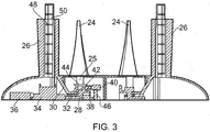
- FIG. 3 shows a more detailed cross-section of the turbine 10.
- the blades 24 of the upstream and downstream rotors 20, 22 are attached at their root 25 to a driveshaft 28 (only shown for the upstream rotor 20).
- the driveshaft 28 rotates within a collar 30 fixed to the struts 26.
- a set of bearings 32 is provided between the surfaces of the driveshaft 28 and the collar 30.
- the driveshaft 28 drives a transmission 34, such as an epicyclic gearbox.
- the transmission drives an electrical generator 36, such as a synchronous machine.
- the electrical generator 36 produces electrical power from the rotation of the driveshaft 28.
- the roots 25 of the blades 24 of each of the upstream and downstream rotors 20, 22 are connected to a variable pitch mechanism 38.
- the variable pitch mechanism 38 comprises an electric motor 40 which drives a gear 42.
- the gear 42 meshes with a bevel gear 44 which is connected to the root 25 of the blade 24 and thus rotation of the electric motor 40 is converted into rotation of the blade 24.
- the electric motor 40 is connected to a supporting structure 46 to ensure that it rotates with the rotor.
- the struts 26 are hollow providing a maintenance passage 48 for the turbine 10.
- the maintenance passage 48 houses a ladder 50 giving maintenance personal access to the inside of the turbine 10 to repair and/or inspect the internal components of the turbine 10, such as the electrical generator 36.
- the upstream rotor 20, upstream hub 16, and the associated blades 24 and struts 26 form an upstream rotor module 52, as shown in Figure 4 .
- the downstream rotor 22, downstream hub 18, and the associated blades 24 and struts 26 form a downstream rotor module 54.
- the upstream and downstream rotor modules 52, 54 also comprise the associated drive elements, such as driveshaft 28, transmission 34 and electrical generator 36, as well as the variable pitch mechanism 38.
- the upstream and downstream rotor modules 52, 54 are individually removable from the turbine 10.
- the turbine 10 is able to operate with one of the upstream and downstream rotor modules 52, 54 removed, albeit with a reduced efficiency. Therefore, maintenance can be carried out on one of the upstream and downstream modules 52, 54 whilst the other of the upstream and downstream modules 52, 54 provides power.
- the struts 26 are provided with locating features (not shown) which align and/or interlock with one another when the modules are correctly aligned.
- the turbine 10 separates the water on the upstream side 4 of the turbine 10 from downstream side 6 side of the turbine 10.
- the water is prevented from passing through the turbine 10, for example, using a sluice (not shown).
- a head of stored water is formed, indicated by arrow 56 in Figure 2 .
- the sluice is opened the stored water is allowed to flow through the turbine.
- the water acts on the blades 24 of the upstream rotor 20, which creates a torque on the upstream rotor as a result of the hydrofoil cross-section of the blades 24. Consequently, the upstream rotor 20 rotates.
- the water acts on the blades 24 of the downstream rotor 22, which creates a torque on the downstream rotor 22. Since the hydrofoil cross-section of the blades 24 of the downstream rotor 22 is oriented in the opposite direction to that of the upstream rotor 20, the downstream rotor 22 rotates in the opposite direction to the upstream rotor 20.
- the rotation of the upstream and downstream rotors 20, 22 drives the electrical generator 36, thus producing useful power.
- the upstream rotor 20 introduces swirl into the incoming flow while the downstream rotor 22 removes this swirl.
- the variable pitch mechanism 38 is actuated electrically to adjust the pitching of both the upstream and downstream rotors 20, 22 such that the exit swirl from the downstream rotor 22 is ideally zero and both rotors 20, 22 run at constant speed.
- the turbine 10 may be operated as a pump.
- the generator 36 operates as a motor and the upstream and downstream rotors 20, 22 rotate pumping water from the downstream side 6 to the upstream side 4.
- the upstream rotor 20 becomes the downstream rotor 22 and the downstream rotor 22 becomes the upstream rotor 20.
- the operation of the turbine is unchanged.
- the upstream or downstream rotor module 52, 54 can be removed from the turbine 10 as previously described.
- the upstream or downstream rotor module 52, 54 can be removed from the turbine 10 using a crane mounted on the tidal barrage 2.
- the turbine 10 may alternatively be run in a free stream (i.e. no duct or barrage) environment.
- the transmission 34 need not be an epicyclic gearbox but is preferably a mechanical, magnetic or hydraulic gearbox. Furthermore, the transmission 34 may be eliminated entirely and a permanent magnet direct-drive electrical generator used.
- variable pitch mechanism 38 may be actuated by a single large gear ring meshing with the bevel gear 44 driven at multiple points by electrical drive.
- variable pitch mechanism 38 may be actuated by an eccentric pin and linear drive mechanism.
- the variable pitch mechanism 38 is advantageously electrically, mechanically or hydraulically actuated.
- Square-to-round transition pieces may be installed on the upstream and downstream sides 6, 8 of the turbine 10 to permit installation in a square duct and minimise expansion and contraction losses.
Description
- This invention relates to a bidirectional water turbine, and particularly but not exclusively, to a bidirectional water turbine for use in a tidal barrage.
- Tidal power harnesses the natural energy produced by the periodic rise and fall of the sea. These tides are created by the rotation of the Earth in the presence of the gravitational fields of the Sun and Moon.
- Various methods may be employed to convert the energy of the tides into useful power. These methods broadly fall into two categories: tidal stream systems and tidal barrages.
- Tidal stream systems operate in a similar manner to wind turbines and usually consist of a turbine which is rotated by the tidal current.
- With a tidal barrage, water is allowed to flow into the area behind the barrage (for example, an estuary) through sluice gates during the flood tide. At high tide, the sluice gates are closed. Since the sea level falls during ebb tide, a head of water is created behind the barrage. Once the head of stored water is of sufficient height, the sluice gates are opened and the stored water is directed to flow through turbines housed within the barrage, thus converting the potential energy stored in the water into useful power.
- A tidal barrage is in use on the Rance river in France. The Rance tidal barrage use 24 turbines, each capable of outputting 10 Megawatts of power. The turbines are low-head bulb turbines which capture energy from the 8 metre tidal range of the river using a 22.5 km2 basin.
-
Figure 1 shows a cross-section through a tidal barrage as used on the Rance river. - The tidal barrage separates an
upstream side 102 and adownstream side 104. A passage is formed through the barrage in which abulb turbine 106 is positioned. The flow of water through the passage andturbine 106 is controlled by first andsecond sluice gates - The
turbine 106 comprises agenerator 112 at an upstream end of theturbine 106. Thegenerator 112 is positioned centrally in theturbine 106 and water is forced to flow around the outside of thegenerator 112 over a set of stationary guide vanes 114 to arotor 116. Therotor 116 is rotatably coupled to thegenerator 112 and comprises a plurality of blades. The blades of therotor 116 have a hydrofoil cross-section which creates torque and rotates therotor 116 when water flows past therotor 116. This turns thegenerator 112 and thus produces useful power. - In order to carry out maintenance on the
turbine 106, it is necessary to close the first andsecond sluice gates turbine 106 out of the passage using anoverhead crane 118. Therefore, it is not possible to generate any power whilst the maintenance is being carried out. - The turbines used in the Rance tidal barrage were intended for bidirectional operation (i.e. generating on both ebb and flood tides). However, the low efficiency of the turbines during flood tide has meant that the turbines have only been used for ebb generation.
- Furthermore, the turbines have reduced the biodiversity of the river because of the high attrition rate of fish as they pass through the turbines.
-
US 20090058093 discloses integrated generator units mounted in an enclosure. Each unit has a plurality of rotational elements that rotate about an axis as fluid passes through the enclosure. An arrangement of magnets is provided such that the rotors generate electrical energy when rotated. -
US 20080315591 discloses a generator for producing electric energy, and a drive shaft which is connected to the generator. The generator comprises a plurality of blades which extend at least partially into the passing water and are set rotating by the water. Said blades are offset in relation to each other and along the drive shaft. - Document
CH-316900 - The present invention provides an improved turbine which addresses some or all of the above identified problems associated with the prior art turbine.
- In accordance with an aspect of the invention, there is provided a bidirectional water turbine comprising: an upstream rotor module and a downstream rotor module, each of the upstream and downstream rotor modules carrying a rotor comprising a plurality of blades; wherein the upstream and downstream rotor modules are individually removable from the turbine, the turbine being configured to operate with one of the upstream and downstream rotor modules removed and , wherein the upstream rotor module (52) and downstream rotor module (54) each further comprise a hub (16, 18) to which the blades (20, 22) are attached, the hubs (16, 18) each being supported by a plurality of hydrodynamically profiled struts (26) which are angled away from their respective rotor (20, 22), the struts (260) being located on an upstream side of the upstream rotor (54) and on a downstream side of the downstream rotor (56.
- By making the upstream and downstream rotor modules individually removable from the turbine, the weight capacity of the crane required to lift them from the turbine is reduced. This enables a crane mounted on the barrage to be used rather than a crane mounted on a floating barge which would be required to remove the whole turbine.
- The number of blades of the upstream rotor may be different from the number of blades of the downstream rotor. This prevents wake loadings from the upstream rotor from impinging on multiple blades of the downstream rotor simultaneously, which would produce significant axial loadings that are detrimental to rotor life. The numbers of blades may be such that there is no common multiple between the upstream and downstream rotors.
- The upstream rotor may rotate in the opposite direction to the downstream rotor.
- The use of contra-rotating upstream and downstream rotors is advantageous in that it substantially reduces the solidity of the rotor blades enabling both the upstream and downstream rotor cascades to be rotated through 180 degrees on the turn of tide such that the downstream rotor now performs the function of the upstream rotor and vice-versa. Furthermore, the contra-rotating upstream and downstream rotors reduce the degree of turning required across each blade, such that the efficiency of the blade at the root is higher and hub blockage may be reduced.
- The cross-section of the upstream and downstream rotor modules may be substantially the same in a plane parallel to an axis of rotation of the rotors.
- The upstream and downstream rotor modules may be installed in the turbine in a back-to-back orientation.
- When installed in the turbine, the upstream and downstream rotor modules may be symmetrical about a plane aligned in a radial direction relative to a longitudinal axis of the turbine.
- The upstream rotor module and downstream rotor module may each further comprise a hub to which the blades are attached, and the hubs may be profiled to prevent separation of exit flow.
- The hubs may each be supported by a plurality of hydrodynamically profiled struts which are angled away from their respective rotor.
- Angling the struts away from the tip of the rotor blade minimises the wake loading at the point where the blade is fastest and the moment to the supporting structure greatest.
- The struts may be located on an upstream side of the upstream rotor and on a downstream side of the downstream rotor.
- The struts may be located between the upstream and downstream rotors.
- The struts may support the hubs from a cylindrical casing.
- A maintenance passage may be provided through the struts.
- The maintenance passage may contain a ladder.
- The struts may be oriented in a non-radial direction.
- The non-radial orientation of the struts prevents the struts from lying parallel to the entire length of one of the blades. This reduces wake loading on the blade.
- The struts may be curved along their length.
- The struts may comprise a locating feature for aligning the upstream and downstream rotors. The locating features may align or interlock when the rotors are correctly aligned.
- In accordance with another aspect of the invention, there is provided a bidirectional water turbine comprising a rotor having a plurality of blades and a variable pitch mechanism for adjusting the pitch of the blades relative to the rotor.
- The water turbine may comprise contra-rotating upstream and downstream rotor modules.
- The variable pitch mechanism permits the rotors to run at a defined, fixed speed enabling the use of a conventional, low-risk drive train arrangement.
- Furthermore, the variable pitch mechanism allows the turbine to operate an efficient pump to maximise power extraction from the barrage and minimise environmental impact.
- The variable pitch mechanism may adjust the pitch of the blades such that exit swirl from the downstream rotor is minimized and/or the downstream and upstream rotors rotate at the same speed.
- The variable pitch mechanism may allow the blades to rotate through at least 180 degrees. The variable pitch mechanism may allow the blades to rotate through at least 320 degrees and/or substantially 360 degrees.
- The blades of the turbine may be rotated through substantially 180 degrees between first and second modes of operation to allow for, for example, a change in tide. The direction of rotation of each rotor may be reversed between the first and second modes of operation.
- This allows the variable pitch mechanism to redistribute lubrication and prevent uneven wear of the component parts.
- A plurality of the bidirectional water turbines may used in a tidal barrage.
- For a better understanding of the present invention and to show more clearly how it may be carried into effect, reference will now be made, by way of example, to the accompanying drawings, in which:-
-
Figure 1 is a cross-section through a tidal barrage as used on the Rance river comprising a prior art turbine; -
Figure 2 is a schematic cross-section through a tidal barrage comprising a bidirectional water turbine in accordance with a first embodiment of the invention; -
Figure 3 is a detailed cross-section through the turbine ofFigure 2 ; and -
Figure 4 is a cross-section through the turbine ofFigure 2 during removal of a rotor module. -
Figure 2 shows a cross-section through atidal barrage 2. Thetidal barrage 2 is typically constructed from concrete and steel and spans across the width of an estuary or other suitable feature separating it from the sea. - The
tidal barrage 2 defines an upstream side 4 and adownstream side 6. A series ofducts 8 are formed through the width of thetidal barrage 2 allowing water to pass through thetidal barrage 2. - A
bidirectional water turbine 10 according to an embodiment of the invention is positioned in each of theducts 8. Theturbine 10 is lowered through anaccess passage 12 formed in the top of thetidal barrage 2. Acylindrical casing 14 of theturbine 10 completes theduct 8 through thetidal barrage 2 and creates a smooth passageway for water to flow. - A
hub assembly 14 is disposed along a longitudinal axis of theturbine 10. Thehub assembly 14 comprises aupstream hub 16 and adownstream hub 18. The upstream anddownstream hubs - An
upstream rotor 20 is rotatably coupled to theupstream hub 16 and adownstream rotor 22 is rotatably coupled to thedownstream hub 18 for rotation about the longitudinal axis of theturbine 10. Each of the upstream anddownstream rotors blades 24 which are spaced radially around the rotor. Theblades 24 extend from the rotor towards thecasing 14, with a small clearance separating the tip of theblade 24 from thecasing 14. Theblades 24 have a hydrofoil cross-section. The orientation of the hydrofoil cross-section of theblades 24 is reversed for the upstream rotor anddownstream rotors upstream rotor 20 is different from the number of blades on thedownstream rotor 22. The - The upstream and
downstream hubs struts 26 which extend from the upstream anddownstream hubs casing 14. As shown inFigure 3 , thestruts 26 are integrally formed with the upsteam anddownstream hubs - The
struts 26 are hydrodynamically profiled to reduce their effect on the flow of water. Furthermore, thestruts 20 are curved along their length in an axial direction and are angled away from theirrespective rotors strut 26 and therotor casing 14 than at the end adjacent thehub struts 26 are also curved or angled in a radial direction so that they are oriented in a non-radial direction. The non-radial orientation of thestruts 26 prevents thestruts 26 from lying parallel to the entire length of one of theblades 24. -
Figure 3 shows a more detailed cross-section of theturbine 10. Theblades 24 of the upstream anddownstream rotors root 25 to a driveshaft 28 (only shown for the upstream rotor 20). Thedriveshaft 28 rotates within acollar 30 fixed to thestruts 26. To allow free rotation of thedriveshaft 28 within thecollar 30, a set ofbearings 32 is provided between the surfaces of thedriveshaft 28 and thecollar 30. - The
driveshaft 28 drives atransmission 34, such as an epicyclic gearbox. In turn, the transmission drives anelectrical generator 36, such as a synchronous machine. Theelectrical generator 36 produces electrical power from the rotation of thedriveshaft 28. - The
roots 25 of theblades 24 of each of the upstream anddownstream rotors variable pitch mechanism 38. Thevariable pitch mechanism 38 comprises anelectric motor 40 which drives agear 42. Thegear 42 meshes with abevel gear 44 which is connected to theroot 25 of theblade 24 and thus rotation of theelectric motor 40 is converted into rotation of theblade 24. Theelectric motor 40 is connected to a supportingstructure 46 to ensure that it rotates with the rotor. - As shown in
Figure 3 , thestruts 26 are hollow providing amaintenance passage 48 for theturbine 10. Themaintenance passage 48 houses aladder 50 giving maintenance personal access to the inside of theturbine 10 to repair and/or inspect the internal components of theturbine 10, such as theelectrical generator 36. - The
upstream rotor 20,upstream hub 16, and the associatedblades 24 and struts 26 form anupstream rotor module 52, as shown inFigure 4 . Similarly, thedownstream rotor 22,downstream hub 18, and the associatedblades 24 and struts 26 form adownstream rotor module 54. The upstream anddownstream rotor modules driveshaft 28,transmission 34 andelectrical generator 36, as well as thevariable pitch mechanism 38. - As shown in
Figure 4 , the upstream anddownstream rotor modules turbine 10. Theturbine 10 is able to operate with one of the upstream anddownstream rotor modules downstream modules downstream modules downstream rotor modules struts 26 are provided with locating features (not shown) which align and/or interlock with one another when the modules are correctly aligned. - In use, the
turbine 10 separates the water on the upstream side 4 of theturbine 10 fromdownstream side 6 side of theturbine 10. The water is prevented from passing through theturbine 10, for example, using a sluice (not shown). As the tide goes out a head of stored water is formed, indicated by arrow 56 inFigure 2 . When the sluice is opened the stored water is allowed to flow through the turbine. The water acts on theblades 24 of theupstream rotor 20, which creates a torque on the upstream rotor as a result of the hydrofoil cross-section of theblades 24. Consequently, theupstream rotor 20 rotates. Similarly, the water acts on theblades 24 of thedownstream rotor 22, which creates a torque on thedownstream rotor 22. Since the hydrofoil cross-section of theblades 24 of thedownstream rotor 22 is oriented in the opposite direction to that of theupstream rotor 20, thedownstream rotor 22 rotates in the opposite direction to theupstream rotor 20. - The rotation of the upstream and
downstream rotors electrical generator 36, thus producing useful power. - The
upstream rotor 20 introduces swirl into the incoming flow while thedownstream rotor 22 removes this swirl. Thevariable pitch mechanism 38 is actuated electrically to adjust the pitching of both the upstream anddownstream rotors downstream rotor 22 is ideally zero and bothrotors - To increase the head of water, the
turbine 10 may be operated as a pump. By inputting power to theturbine 10, thegenerator 36 operates as a motor and the upstream anddownstream rotors downstream side 6 to the upstream side 4. - During flood tide, the
upstream rotor 20 becomes thedownstream rotor 22 and thedownstream rotor 22 becomes theupstream rotor 20. However, the operation of the turbine is unchanged. - Minor maintenance may be carried out on the
turbine 10 using themaintenance passage 48 andladder 50 to access the inside of theturbine 10. If more major maintenance is required or replacement of a module, the upstream ordownstream rotor module turbine 10 as previously described. The upstream ordownstream rotor module turbine 10 using a crane mounted on thetidal barrage 2. - Although the present invention has been described with reference to a tidal barrage, the
turbine 10 may alternatively be run in a free stream (i.e. no duct or barrage) environment. - The
transmission 34 need not be an epicyclic gearbox but is preferably a mechanical, magnetic or hydraulic gearbox. Furthermore, thetransmission 34 may be eliminated entirely and a permanent magnet direct-drive electrical generator used. - Alternative embodiments of the
variable pitch mechanism 38 could be used. For example, thevariable pitch mechanism 38 may be actuated by a single large gear ring meshing with thebevel gear 44 driven at multiple points by electrical drive. Alternatively, thevariable pitch mechanism 38 may be actuated by an eccentric pin and linear drive mechanism. Thevariable pitch mechanism 38 is advantageously electrically, mechanically or hydraulically actuated. - Square-to-round transition pieces may be installed on the upstream and
downstream sides turbine 10 to permit installation in a square duct and minimise expansion and contraction losses.
Claims (14)
- A bidirectional water turbine (10) comprising:an upstream rotor module (52) and a downstream rotor module (54), each of the upstream and downstream rotor modules (52, 54) carrying a rotor (20, 22) comprising a plurality of blades (24);wherein the upstream and downstream rotor modules (52, 54) are individually removable from the turbine (10), the turbine (10) being configured to operate with one of the upstream and downstream rotor modules (52, 54) removed and characterised by the fact that the upstream rotor module (52) and downstream rotor module (54) each further comprise a hub (16, 18) to which the blades (20, 22) are attached, the hubs (16, 18) each being supported by a plurality of hydrodynamically profiled struts (26) which are angled away from their respective rotor (20, 22), the struts (260) being located on an upstream side of the upstream rotor (54) and on a downstream side of the downstream rotor (56).
- A bidirectional water turbine as claimed in claim 1, wherein the upstream and downstream rotors (52, 54) are contra-rotating.
- A bidirectional water turbine as claimed in claim 1 or 2, wherein the cross-section of the upstream and downstream rotor modules (52, 54) is substantially the same in a plane parallel to an axis of rotation of the rotors (20, 22), and the upstream and downstream rotor modules (52, 54) may be installed in the turbine (10) in a back-to-back orientation.
- A bidirectional water turbine as claimed in any one of the preceding claims, wherein, when installed in the turbine, the upstream and downstream rotor modules (52, 54) are symmetrical about a plane aligned in a radial direction relative to a longitudinal axis of the turbine (10).
- A bidirectional water turbine as claimed in any one of the preceding claims, wherein the hubs (16, 18) are profiled to prevent separation of exit flow.
- A bidirectional water turbine as claimed in claim 5, wherein the struts (26) are located between the upstream and downstream rotors (52, 54).
- A bidirectional water turbine as claimed in claims 5 or 6, wherein the struts are oriented in a non-radial direction.
- A bidirectional water turbine as claimed in any one of claims 5 to 7, wherein the struts comprise a locating feature for aligning the upstream and downstream rotors.
- A bidirectional water turbine as claimed in any of the preceding claims, wherein the variable pitch mechanism adjusts the pitch of the blades such that exit swirl from the downstream rotor is minimized and/or the downstream and upstream rotors rotate at the same speed.
- A bidirectional water turbine as claimed in any of the preceding claims, wherein the variable pitch mechanism allows the blades to rotate through substantially 360 degrees.
- A bidirectional water turbine as claimed in any of the preceding claims, wherein the upstream and downstream rotors are arranged for contra-rotation in use and each comprise a variable pitch mechanism.
- A bidirectional water turbine according to any one of the preceding claims, wherein the pitch mechanism allows the blades to rotate through at least 180 degrees between first and second modes of operation.
- A bidirectional water turbine according to claim 12, wherein the direction of rotation of each of the upstream and downstream rotor modules is reversed between the first and second modes of operation.
- A tidal barrage comprising a plurality of bidirectional water turbines as claimed in any one of the preceding claims.
Applications Claiming Priority (2)
| Application Number | Priority Date | Filing Date | Title |
|---|---|---|---|
| GB1001871.1A GB2477533B (en) | 2010-02-05 | 2010-02-05 | A bidirectional water turbine |
| PCT/EP2011/050744 WO2011095398A2 (en) | 2010-02-05 | 2011-01-20 | A bidirectional water turbine |
Publications (2)
| Publication Number | Publication Date |
|---|---|
| EP2531718A2 EP2531718A2 (en) | 2012-12-12 |
| EP2531718B1 true EP2531718B1 (en) | 2016-03-30 |
Family
ID=42082506
Family Applications (1)
| Application Number | Title | Priority Date | Filing Date |
|---|---|---|---|
| EP11701388.8A Active EP2531718B1 (en) | 2010-02-05 | 2011-01-20 | A bidirectional water turbine |
Country Status (6)
| Country | Link |
|---|---|
| US (1) | US20130071240A1 (en) |
| EP (1) | EP2531718B1 (en) |
| KR (1) | KR20120115572A (en) |
| CA (1) | CA2791900C (en) |
| GB (1) | GB2477533B (en) |
| WO (1) | WO2011095398A2 (en) |
Families Citing this family (12)
| Publication number | Priority date | Publication date | Assignee | Title |
|---|---|---|---|---|
| GB2494138A (en) | 2011-08-31 | 2013-03-06 | Rolls Royce Plc | Exit swirl sensor arrangement for a tidal generator |
| JP6188133B2 (en) * | 2013-06-28 | 2017-08-30 | 国立研究開発法人農業・食品産業技術総合研究機構 | Coaxial pump blades integrating water wheel blades and pump blades, and pumping device using the same |
| KR101711630B1 (en) * | 2014-09-23 | 2017-03-03 | 한국생산기술연구원 | An optimal design method of counter-rotating type pump-turbine, a counter-rotating type pump-turbine and self generating system designed by the method |
| EP3051123A1 (en) * | 2015-01-28 | 2016-08-03 | ALSTOM Renewable Technologies | Method for controlling a turbine |
| EP3104000A1 (en) * | 2015-06-12 | 2016-12-14 | ALSTOM Renewable Technologies | Runner for a tidal power plant and tidal power plant comprising such a runner |
| US10910936B2 (en) | 2015-10-14 | 2021-02-02 | Emrgy, Inc. | Cycloidal magnetic gear system |
| WO2017172747A1 (en) * | 2016-03-28 | 2017-10-05 | Emrgy, Inc. | Turbine hydrokinetic energy system utilizing cycloidal magnetic gears |
| US11434866B2 (en) * | 2017-06-02 | 2022-09-06 | Donald Hollis Gehring | Water current catcher system for hydroelectricity generation |
| MX2020002902A (en) | 2017-09-15 | 2020-10-01 | Emrgy Inc | Hydro transition systems and methods of using the same. |
| US11261574B1 (en) | 2018-06-20 | 2022-03-01 | Emrgy Inc. | Cassette |
| US11713743B2 (en) | 2019-03-19 | 2023-08-01 | Emrgy Inc. | Flume |
| CN110608128B (en) * | 2019-10-10 | 2021-03-30 | 杭州江河水电科技有限公司 | Tidal current energy power generation device |
Family Cites Families (10)
| Publication number | Priority date | Publication date | Assignee | Title |
|---|---|---|---|---|
| CH316900A (en) * | 1953-04-15 | 1956-10-31 | Escher Wyss Ag | Hydroelectric machine system with counter-rotating impellers |
| US5242265A (en) * | 1990-07-23 | 1993-09-07 | General Electric Company | Aircraft pitch change mechanism |
| NL1013559C2 (en) * | 1999-11-11 | 2001-05-28 | Peter Alexander Josephus Pas | System for producing hydrogen from water using a water stream such as a wave stream or tidal stream. |
| GB0123802D0 (en) * | 2001-10-04 | 2001-11-21 | Rotech Holdings Ltd | Power generator and turbine unit |
| AT413425B (en) * | 2003-03-06 | 2006-02-15 | Va Tech Hydro Gmbh & Co | DEVICE FOR GENERATING ELECTRICAL ENERGY |
| NO321755B1 (en) * | 2003-06-25 | 2006-07-03 | Sinvent As | Method and apparatus for converting energy from / to water under pressure. |
| JP2009522481A (en) * | 2005-12-29 | 2009-06-11 | ハーマン、ゲオルク | Apparatus and system for generating regenerative hydraulic energy and renewable hydraulic energy |
| US20080018115A1 (en) * | 2006-07-20 | 2008-01-24 | Boray Technologies, Inc. | Semi-submersible hydroelectric power plant |
| BRPI0810029A2 (en) * | 2007-04-17 | 2017-05-02 | Aerokinetic Energy Corp | fluid driven generator |
| GB0809745D0 (en) * | 2008-05-29 | 2008-07-09 | Evans Rupert J A | A barrage system for capturing tehenergy from a tidal stream |
-
2010
- 2010-02-05 GB GB1001871.1A patent/GB2477533B/en active Active
-
2011
- 2011-01-20 WO PCT/EP2011/050744 patent/WO2011095398A2/en active Application Filing
- 2011-01-20 KR KR1020127023224A patent/KR20120115572A/en not_active Application Discontinuation
- 2011-01-20 CA CA2791900A patent/CA2791900C/en active Active
- 2011-01-20 US US13/581,921 patent/US20130071240A1/en not_active Abandoned
- 2011-01-20 EP EP11701388.8A patent/EP2531718B1/en active Active
Also Published As
| Publication number | Publication date |
|---|---|
| CA2791900A1 (en) | 2011-08-11 |
| CA2791900C (en) | 2017-11-07 |
| GB2477533A (en) | 2011-08-10 |
| US20130071240A1 (en) | 2013-03-21 |
| GB2477533B (en) | 2012-05-30 |
| EP2531718A2 (en) | 2012-12-12 |
| GB201001871D0 (en) | 2010-03-24 |
| WO2011095398A2 (en) | 2011-08-11 |
| KR20120115572A (en) | 2012-10-18 |
| WO2011095398A3 (en) | 2011-12-29 |
Similar Documents
| Publication | Publication Date | Title |
|---|---|---|
| EP2531718B1 (en) | A bidirectional water turbine | |
| EP2531717B1 (en) | A bidirectional water turbine | |
| AU2007271896B2 (en) | Turbines having a debris release chute | |
| US7986054B2 (en) | Magnus force fluid flow energy harvester | |
| AU2002328217B2 (en) | Underwater ducted turbine | |
| US8070444B2 (en) | Turbine with coaxial sets of blades | |
| NZ531809A (en) | Water current turbine sleeve mounting | |
| US20180195582A1 (en) | Control apparatus and method for variable renewable energy | |
| EP3426913B1 (en) | An energy generating arrangement powered by tidal water and a method for providing such an arrangement | |
| US10941749B2 (en) | Speed converter-controlled river turbines | |
| EP2718559B1 (en) | A turbine array and a method of controlling a turbine array during a loss-of-grid event | |
| WO2006033598A1 (en) | Dam-less tractive power plant | |
| US10982645B2 (en) | River and tidal turbine with power control | |
| AU2017100917A4 (en) | Novel power generation device using wave kinetic energy | |
| WO2012127218A2 (en) | Turbine apparatus | |
| KR20120041030A (en) | Apparatus for generating power using the flow of water having self-buoyancy force | |
| CA2873584A1 (en) | Hydromotive machine |
Legal Events
| Date | Code | Title | Description |
|---|---|---|---|
| PUAI | Public reference made under article 153(3) epc to a published international application that has entered the european phase |
Free format text: ORIGINAL CODE: 0009012 |
|
| 17P | Request for examination filed |
Effective date: 20120831 |
|
| AK | Designated contracting states |
Kind code of ref document: A2 Designated state(s): AL AT BE BG CH CY CZ DE DK EE ES FI FR GB GR HR HU IE IS IT LI LT LU LV MC MK MT NL NO PL PT RO RS SE SI SK SM TR |
|
| DAX | Request for extension of the european patent (deleted) | ||
| 17Q | First examination report despatched |
Effective date: 20150420 |
|
| RAP1 | Party data changed (applicant data changed or rights of an application transferred) |
Owner name: ROLLS-ROYCE PLC |
|
| GRAP | Despatch of communication of intention to grant a patent |
Free format text: ORIGINAL CODE: EPIDOSNIGR1 |
|
| INTG | Intention to grant announced |
Effective date: 20160104 |
|
| GRAS | Grant fee paid |
Free format text: ORIGINAL CODE: EPIDOSNIGR3 |
|
| GRAA | (expected) grant |
Free format text: ORIGINAL CODE: 0009210 |
|
| AK | Designated contracting states |
Kind code of ref document: B1 Designated state(s): AL AT BE BG CH CY CZ DE DK EE ES FI FR GB GR HR HU IE IS IT LI LT LU LV MC MK MT NL NO PL PT RO RS SE SI SK SM TR |
|
| REG | Reference to a national code |
Ref country code: GB Ref legal event code: FG4D |
|
| REG | Reference to a national code |
Ref country code: CH Ref legal event code: EP |
|
| REG | Reference to a national code |
Ref country code: AT Ref legal event code: REF Ref document number: 785695 Country of ref document: AT Kind code of ref document: T Effective date: 20160415 |
|
| REG | Reference to a national code |
Ref country code: IE Ref legal event code: FG4D |
|
| REG | Reference to a national code |
Ref country code: DE Ref legal event code: R096 Ref document number: 602011024591 Country of ref document: DE |
|
| REG | Reference to a national code |
Ref country code: LT Ref legal event code: MG4D |
|
| PG25 | Lapsed in a contracting state [announced via postgrant information from national office to epo] |
Ref country code: FI Free format text: LAPSE BECAUSE OF FAILURE TO SUBMIT A TRANSLATION OF THE DESCRIPTION OR TO PAY THE FEE WITHIN THE PRESCRIBED TIME-LIMIT Effective date: 20160330 Ref country code: NO Free format text: LAPSE BECAUSE OF FAILURE TO SUBMIT A TRANSLATION OF THE DESCRIPTION OR TO PAY THE FEE WITHIN THE PRESCRIBED TIME-LIMIT Effective date: 20160630 Ref country code: GR Free format text: LAPSE BECAUSE OF FAILURE TO SUBMIT A TRANSLATION OF THE DESCRIPTION OR TO PAY THE FEE WITHIN THE PRESCRIBED TIME-LIMIT Effective date: 20160701 Ref country code: HR Free format text: LAPSE BECAUSE OF FAILURE TO SUBMIT A TRANSLATION OF THE DESCRIPTION OR TO PAY THE FEE WITHIN THE PRESCRIBED TIME-LIMIT Effective date: 20160330 |
|
| REG | Reference to a national code |
Ref country code: NL Ref legal event code: MP Effective date: 20160330 |
|
| REG | Reference to a national code |
Ref country code: AT Ref legal event code: MK05 Ref document number: 785695 Country of ref document: AT Kind code of ref document: T Effective date: 20160330 |
|
| PG25 | Lapsed in a contracting state [announced via postgrant information from national office to epo] |
Ref country code: SE Free format text: LAPSE BECAUSE OF FAILURE TO SUBMIT A TRANSLATION OF THE DESCRIPTION OR TO PAY THE FEE WITHIN THE PRESCRIBED TIME-LIMIT Effective date: 20160330 Ref country code: LT Free format text: LAPSE BECAUSE OF FAILURE TO SUBMIT A TRANSLATION OF THE DESCRIPTION OR TO PAY THE FEE WITHIN THE PRESCRIBED TIME-LIMIT Effective date: 20160330 Ref country code: RS Free format text: LAPSE BECAUSE OF FAILURE TO SUBMIT A TRANSLATION OF THE DESCRIPTION OR TO PAY THE FEE WITHIN THE PRESCRIBED TIME-LIMIT Effective date: 20160330 Ref country code: LV Free format text: LAPSE BECAUSE OF FAILURE TO SUBMIT A TRANSLATION OF THE DESCRIPTION OR TO PAY THE FEE WITHIN THE PRESCRIBED TIME-LIMIT Effective date: 20160330 |
|
| PG25 | Lapsed in a contracting state [announced via postgrant information from national office to epo] |
Ref country code: NL Free format text: LAPSE BECAUSE OF FAILURE TO SUBMIT A TRANSLATION OF THE DESCRIPTION OR TO PAY THE FEE WITHIN THE PRESCRIBED TIME-LIMIT Effective date: 20160330 |
|
| PG25 | Lapsed in a contracting state [announced via postgrant information from national office to epo] |
Ref country code: EE Free format text: LAPSE BECAUSE OF FAILURE TO SUBMIT A TRANSLATION OF THE DESCRIPTION OR TO PAY THE FEE WITHIN THE PRESCRIBED TIME-LIMIT Effective date: 20160330 Ref country code: IS Free format text: LAPSE BECAUSE OF FAILURE TO SUBMIT A TRANSLATION OF THE DESCRIPTION OR TO PAY THE FEE WITHIN THE PRESCRIBED TIME-LIMIT Effective date: 20160730 Ref country code: PL Free format text: LAPSE BECAUSE OF FAILURE TO SUBMIT A TRANSLATION OF THE DESCRIPTION OR TO PAY THE FEE WITHIN THE PRESCRIBED TIME-LIMIT Effective date: 20160330 |
|
| PG25 | Lapsed in a contracting state [announced via postgrant information from national office to epo] |
Ref country code: PT Free format text: LAPSE BECAUSE OF FAILURE TO SUBMIT A TRANSLATION OF THE DESCRIPTION OR TO PAY THE FEE WITHIN THE PRESCRIBED TIME-LIMIT Effective date: 20160801 Ref country code: SM Free format text: LAPSE BECAUSE OF FAILURE TO SUBMIT A TRANSLATION OF THE DESCRIPTION OR TO PAY THE FEE WITHIN THE PRESCRIBED TIME-LIMIT Effective date: 20160330 Ref country code: SK Free format text: LAPSE BECAUSE OF FAILURE TO SUBMIT A TRANSLATION OF THE DESCRIPTION OR TO PAY THE FEE WITHIN THE PRESCRIBED TIME-LIMIT Effective date: 20160330 Ref country code: CZ Free format text: LAPSE BECAUSE OF FAILURE TO SUBMIT A TRANSLATION OF THE DESCRIPTION OR TO PAY THE FEE WITHIN THE PRESCRIBED TIME-LIMIT Effective date: 20160330 Ref country code: AT Free format text: LAPSE BECAUSE OF FAILURE TO SUBMIT A TRANSLATION OF THE DESCRIPTION OR TO PAY THE FEE WITHIN THE PRESCRIBED TIME-LIMIT Effective date: 20160330 Ref country code: RO Free format text: LAPSE BECAUSE OF FAILURE TO SUBMIT A TRANSLATION OF THE DESCRIPTION OR TO PAY THE FEE WITHIN THE PRESCRIBED TIME-LIMIT Effective date: 20160330 Ref country code: ES Free format text: LAPSE BECAUSE OF FAILURE TO SUBMIT A TRANSLATION OF THE DESCRIPTION OR TO PAY THE FEE WITHIN THE PRESCRIBED TIME-LIMIT Effective date: 20160330 |
|
| PG25 | Lapsed in a contracting state [announced via postgrant information from national office to epo] |
Ref country code: IT Free format text: LAPSE BECAUSE OF FAILURE TO SUBMIT A TRANSLATION OF THE DESCRIPTION OR TO PAY THE FEE WITHIN THE PRESCRIBED TIME-LIMIT Effective date: 20160330 Ref country code: BE Free format text: LAPSE BECAUSE OF FAILURE TO SUBMIT A TRANSLATION OF THE DESCRIPTION OR TO PAY THE FEE WITHIN THE PRESCRIBED TIME-LIMIT Effective date: 20160330 |
|
| REG | Reference to a national code |
Ref country code: DE Ref legal event code: R097 Ref document number: 602011024591 Country of ref document: DE |
|
| REG | Reference to a national code |
Ref country code: FR Ref legal event code: PLFP Year of fee payment: 7 |
|
| PG25 | Lapsed in a contracting state [announced via postgrant information from national office to epo] |
Ref country code: DK Free format text: LAPSE BECAUSE OF FAILURE TO SUBMIT A TRANSLATION OF THE DESCRIPTION OR TO PAY THE FEE WITHIN THE PRESCRIBED TIME-LIMIT Effective date: 20160330 |
|
| PLBE | No opposition filed within time limit |
Free format text: ORIGINAL CODE: 0009261 |
|
| STAA | Information on the status of an ep patent application or granted ep patent |
Free format text: STATUS: NO OPPOSITION FILED WITHIN TIME LIMIT |
|
| 26N | No opposition filed |
Effective date: 20170103 |
|
| PG25 | Lapsed in a contracting state [announced via postgrant information from national office to epo] |
Ref country code: SI Free format text: LAPSE BECAUSE OF FAILURE TO SUBMIT A TRANSLATION OF THE DESCRIPTION OR TO PAY THE FEE WITHIN THE PRESCRIBED TIME-LIMIT Effective date: 20160330 |
|
| REG | Reference to a national code |
Ref country code: CH Ref legal event code: PL |
|
| PG25 | Lapsed in a contracting state [announced via postgrant information from national office to epo] |
Ref country code: MC Free format text: LAPSE BECAUSE OF FAILURE TO SUBMIT A TRANSLATION OF THE DESCRIPTION OR TO PAY THE FEE WITHIN THE PRESCRIBED TIME-LIMIT Effective date: 20160330 |
|
| PG25 | Lapsed in a contracting state [announced via postgrant information from national office to epo] |
Ref country code: LI Free format text: LAPSE BECAUSE OF NON-PAYMENT OF DUE FEES Effective date: 20170131 Ref country code: CH Free format text: LAPSE BECAUSE OF NON-PAYMENT OF DUE FEES Effective date: 20170131 |
|
| REG | Reference to a national code |
Ref country code: IE Ref legal event code: MM4A |
|
| PG25 | Lapsed in a contracting state [announced via postgrant information from national office to epo] |
Ref country code: LU Free format text: LAPSE BECAUSE OF NON-PAYMENT OF DUE FEES Effective date: 20170120 |
|
| REG | Reference to a national code |
Ref country code: FR Ref legal event code: PLFP Year of fee payment: 8 |
|
| PG25 | Lapsed in a contracting state [announced via postgrant information from national office to epo] |
Ref country code: IE Free format text: LAPSE BECAUSE OF NON-PAYMENT OF DUE FEES Effective date: 20170120 |
|
| PG25 | Lapsed in a contracting state [announced via postgrant information from national office to epo] |
Ref country code: MT Free format text: LAPSE BECAUSE OF NON-PAYMENT OF DUE FEES Effective date: 20170120 |
|
| PG25 | Lapsed in a contracting state [announced via postgrant information from national office to epo] |
Ref country code: AL Free format text: LAPSE BECAUSE OF FAILURE TO SUBMIT A TRANSLATION OF THE DESCRIPTION OR TO PAY THE FEE WITHIN THE PRESCRIBED TIME-LIMIT Effective date: 20160330 |
|
| PG25 | Lapsed in a contracting state [announced via postgrant information from national office to epo] |
Ref country code: HU Free format text: LAPSE BECAUSE OF FAILURE TO SUBMIT A TRANSLATION OF THE DESCRIPTION OR TO PAY THE FEE WITHIN THE PRESCRIBED TIME-LIMIT; INVALID AB INITIO Effective date: 20110120 |
|
| PG25 | Lapsed in a contracting state [announced via postgrant information from national office to epo] |
Ref country code: BG Free format text: LAPSE BECAUSE OF FAILURE TO SUBMIT A TRANSLATION OF THE DESCRIPTION OR TO PAY THE FEE WITHIN THE PRESCRIBED TIME-LIMIT Effective date: 20160330 |
|
| PG25 | Lapsed in a contracting state [announced via postgrant information from national office to epo] |
Ref country code: CY Free format text: LAPSE BECAUSE OF NON-PAYMENT OF DUE FEES Effective date: 20160330 |
|
| PG25 | Lapsed in a contracting state [announced via postgrant information from national office to epo] |
Ref country code: MK Free format text: LAPSE BECAUSE OF FAILURE TO SUBMIT A TRANSLATION OF THE DESCRIPTION OR TO PAY THE FEE WITHIN THE PRESCRIBED TIME-LIMIT Effective date: 20160330 |
|
| PG25 | Lapsed in a contracting state [announced via postgrant information from national office to epo] |
Ref country code: TR Free format text: LAPSE BECAUSE OF FAILURE TO SUBMIT A TRANSLATION OF THE DESCRIPTION OR TO PAY THE FEE WITHIN THE PRESCRIBED TIME-LIMIT Effective date: 20160330 |
|
| PGFP | Annual fee paid to national office [announced via postgrant information from national office to epo] |
Ref country code: FR Payment date: 20230124 Year of fee payment: 13 |
|
| PGFP | Annual fee paid to national office [announced via postgrant information from national office to epo] |
Ref country code: GB Payment date: 20230124 Year of fee payment: 13 Ref country code: DE Payment date: 20230127 Year of fee payment: 13 |
|
| P01 | Opt-out of the competence of the unified patent court (upc) registered |
Effective date: 20230528 |