EP2530797A1 - Medium voltage switchgear - Google Patents
Medium voltage switchgear Download PDFInfo
- Publication number
- EP2530797A1 EP2530797A1 EP11168512A EP11168512A EP2530797A1 EP 2530797 A1 EP2530797 A1 EP 2530797A1 EP 11168512 A EP11168512 A EP 11168512A EP 11168512 A EP11168512 A EP 11168512A EP 2530797 A1 EP2530797 A1 EP 2530797A1
- Authority
- EP
- European Patent Office
- Prior art keywords
- medium voltage
- voltage switchgear
- opening
- plate
- closing
- Prior art date
- Legal status (The legal status is an assumption and is not a legal conclusion. Google has not performed a legal analysis and makes no representation as to the accuracy of the status listed.)
- Granted
Links
Images


Classifications
-
- H—ELECTRICITY
- H02—GENERATION; CONVERSION OR DISTRIBUTION OF ELECTRIC POWER
- H02B—BOARDS, SUBSTATIONS OR SWITCHING ARRANGEMENTS FOR THE SUPPLY OR DISTRIBUTION OF ELECTRIC POWER
- H02B13/00—Arrangement of switchgear in which switches are enclosed in, or structurally associated with, a casing, e.g. cubicle
- H02B13/02—Arrangement of switchgear in which switches are enclosed in, or structurally associated with, a casing, e.g. cubicle with metal casing
- H02B13/025—Safety arrangements, e.g. in case of excessive pressure or fire due to electrical defect
-
- H—ELECTRICITY
- H02—GENERATION; CONVERSION OR DISTRIBUTION OF ELECTRIC POWER
- H02B—BOARDS, SUBSTATIONS OR SWITCHING ARRANGEMENTS FOR THE SUPPLY OR DISTRIBUTION OF ELECTRIC POWER
- H02B11/00—Switchgear having carriage withdrawable for isolation
- H02B11/12—Switchgear having carriage withdrawable for isolation with isolation by horizontal withdrawal
- H02B11/127—Withdrawal mechanism
Definitions
- the present invention relates to a medium voltage switchgear with improved features, and in particular to a medium voltage switchgear having a circuit breaker in the so-called withdrawable configuration.
- medium voltage is referred to applications in the range from 1 kV up to some tens of KV, for example 52 kV
- a medium voltage switchgear 1 is well known in the art and it usually consists of a casing 2 which defines an internal volume 3 for housing a circuit breaker assembly 4 and, e.g., a bus-bar assembly 39, as well as other systems, such as a feeder system and possible auxiliary equipment.
- the circuit breaker assembly 4 is normally positioned inside a circuit breaker compartment, said circuit breaker assembly 4 being, in the so-called withdrawable configuration, movable between a service position, in which it is connected to the bus-bar and feeder systems, and a test/disconnected position in which it is isolated from the bus-bar and feeder systems. Depending on the application a grounding position is also possible.
- the circuit breaker assembly 4 can be moved from the service position shown in said figure, to a test/disconnected position and/or a grounding position, by sliding said assembly 4 toward the right-hand side of the figure.
- the circuit breaker assembly 4 is normally positioned on a sliding frame (not-shown) actuated from the outside of the casing 2.
- the sliding frame and its operation are well known in the art and will not be described in details here.
- an opening 5 is normally present of the front panel 21 of the switchgear 1, so as to allow the insertion and extraction of an operating handle.
- a first drawback of the known solutions is due to the fact that the opening 5 allows a direct communication between the circuit breaker compartment and the outside of the switchgear 1, with safety concerns in case of faults, such as an internal arc.
- the present invention is aimed at providing a medium voltage switchgear in which the insertion/withdrawing operation of the circuit breaker can be carried out in an always safe way.
- a further object of the present invention is to provide a medium voltage switchgear in which the separation between the inside and outside is always maintained.
- Another object of the present invention is to provide a medium voltage switchgear having a reduced number of mechanical parts.
- Another object of the present invention is to provide a medium voltage switchgear having a withdrawing system of the circuit breaker with improved functionality.
- Still another object of the present invention is to provide a medium voltage switchgear with reduced manufacturing, installation and maintenance costs.
- the present invention relates to a medium voltage switchgear which is characterized in that it comprises a casing defining an internal volume for housing at least a circuit breaker assembly movable between at least two operative positions, said casing comprising a front panel provided with an opening for the insertion of an operating handle for actuating the movement of said circuit breaker assembly between said operative positions, a closing and retaining device being positioned in correspondence of said opening and being movable between a closed position when said operating handle is not inserted and an open position for allowing insertion of said operating handle, said closing and retaining device comprising locking means for retaining said operating handle in position when inserted in said opening.
- a closing and retaining device allows to keep the opening always covered and protected, thereby always separating the circuit breaker compartment from the outside of the switchgear
- the medium voltage switchgear according to the invention preferably comprises a closing and retaining device comprising elastic retaining means, e.g. springs or equivalent means, for keeping it in said closed position, and opening means for its opening, said opening means comprising, for example, a manually operated knob that can be actuated by an operator.
- elastic retaining means e.g. springs or equivalent means
- said closing and retaining device comprises a first and a second plate respectively provided with a first and a second hole axially aligned with said opening when said closing and retaining device is in the open position, said first and a second plate covering and closing said opening when said closing and retaining device is in the closed position.
- said first and a second plate are preferably hinged on a common point, e.g. on the front panel, and rotate in opposite directions when passing from said closed to said open position.
- said first and a second plate are substantially C-shaped and comprises a first and a second lateral portion extending form a central portion.
- said first and a second plate respectively comprise a first and a second actuating surface extending therefrom and interacting with an actuating cam operatively coupled with said opening means.
- said first and second actuating surfaces can be positioned on the central portion of said first and a second plate which can be hinged on said common point in correspondence of said first lateral portion, while said first and second hole can be positioned on said second lateral portion of said first and second plate.
- said locking means comprise a cutout portion on the periphery of said first and second hole for engaging and retaining said operating handle.
- a medium voltage switchgear designed with the reference number 1, comprises, in its more general definition, a casing 2 which defines an internal volume 3.
- At least a circuit breaker assembly 4 is housed inside the internal volume 3, said circuit breaker assembly 4 being movable between at least two operative positions, e.g. a test/disconnected position and a service position in which it is connected to the bus bar assembly 39.
- operative positions e.g. a grounding position, are also possible.
- the casing 2 normally comprises a front panel 21, e.g. a door, provided with an opening 5 for the insertion of an operating handle 8 which is used for actuating the movement of the circuit breaker assembly 4 between said operative positions.
- a front panel 21 e.g. a door
- an operating handle 8 which is used for actuating the movement of the circuit breaker assembly 4 between said operative positions.
- one of the characterizing features of the medium voltage switchgear according to the invention derives for the presence of a closing and retaining device 6 which is positioned in correspondence of said opening 5.
- figures 2-8 for sake of clarity, the front panel 21 is not shown.
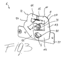
- figures 3 , 4 , 6 , and 8 show the side of the device 6 facing toward the outside of the switchgear, i.e., the side of the device positioned on the inside surface of the panel 21 and therefore normally non visible;
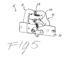
- figures 2 , 5 , and 7 show the side of the device 6 facing toward the inside of the switchgear, i.e. facing inside the circuit breaker compartment.
- the closing and retaining device 6 is shown in the open position, while in figures 4 it is shown in the closed position.
- figures 5 and 6 the operating handle is inserted but not locked, while in figure 7 and 8 the operating handle is inserted and locked into place.
- the device 6 is movable between a closed position ( figs. 4 ) when said operating handle 8 is not inserted and an open position ( figs. 2 , 3 , 5 , and 6 ) for allowing insertion of said operating handle 8.
- the closing and retaining device 6 further comprises locking means for retaining said operating handle 8 in position when it is inserted in said opening 5 ( figs. 7 and 8 ).
- the closing and retaining device 6 comprises elastic retaining means for keeping it in said closed position and opening means for its opening, said opening means being, for instance, a manually operated knob 71 positioned on the outside of the front panel 21.
- a fixing plate 77 can be used to fix part of the device 6 to the panel 21.
- said closing and retaining device 6 comprises a first 11 and a second 12 plate which are respectively provided with a first 811 and a second 812 hole axially aligned with the opening 5 when said closing and retaining device 6 is in the open position, said first 11 and second 12 plate covering and closing said opening 5 when said closing and retaining device 6 is in the closed position.
- the first 11 and a second 12 plate are hinged on a common point 15 and rotate in opposite directions when passing from said closed to said open position, said common point 15 being preferably positioned on the front panel 21.
- the plate 12 rotates clockwise and the plate 11 rotates counterclockwise bringing the device 6 in the position of figures 2 and 3 .
- the first 11 and a second 12 plate are substantially C-shaped and comprises a first 41, 51 and a second 42, 52 lateral portion extending form a central portion 43, 53. Moreover, the first 11 and a second 12 plate respectively comprise a first 111 and a second 112 actuating surfaces extending therefrom and interacting with an actuating cam 20 which is operatively coupled with the opening means 71.
- the first 111 and second 112 actuating surfaces can be conveniently positioned on the central portion 43, 53 of said first 11 and a second 12 plate.
- first 11 and second 12 plate can be hinged on said common point 15 in correspondence of said first 41, 51 lateral portion, and said first 811 and second 812 hole can be positioned on said second 42, 52 lateral portion of said first 11 and a second 12 plate.
- the locking means comprise a cutout portion 91, 92 on the periphery of said first 811 and second 812 hole for engaging and retaining said operating handle 8.
- the elastic retaining means can comprise, for example, a first spring 27 operatively coupled to said first 11 and second 12 plate and a second spring 28 operatively coupled to said actuating cam 20.
- the operating sequence can be described as follows.
- the closing and retaining device 6 is in the closed position and the plates 11 and 12 are kept in such position by the spring 27 acting thereon.
- the second lateral portions 42, 52 of the plates 11 and 12 completely cover the opening 5, thereby separating the circuit breaker compartment from the outside of the switchgear 1.
- the cam 20 By acting on the knob 71, the cam 20 is rotated so as to act on the actuating surfaces 111 of the first plate 11 and 112 of the second plate 12. In this way, the plate 11 rotates counterclockwise and the plate 12 rotates clockwise so as to reach the position of figures 2 and 3 in which the first 811 and second 812 hole are axially aligned with the opening 5.
- the cam 20 By releasing the action on the knob 71, the cam 20 tends to return to the initial position due to the action of the spring 28. At the same time, since the cam 20 is no longer acting on the actuating surfaces 111 and 112, also the plates 11 and 12 tends to return to the initial position du to the action of the spring 27. In this way, the cutout portions 91 and 92 on the periphery of the first 811 and second 812 hole engage the stem 82 of the operating handle 8, thereby locking it into the inserted position.
- the operating knob 71 is actuated so as to rotate the cam 70 which acts on the actuating surfaces 111 and 112 determining rotation of the plates 11 and 12 until they reach the position of figures 5 and 6 .
- the operating handle is unlocked and can be removed with the device 6 remaining in the position of figures 2 and 3 .
- the knob 71 by releasing the knob 71, the cam 20 is restored in the position of figure 4 due to the action of the spring 28; at the same time, the plates 11 and 12 return to the position of figure 4 due to the action of the spring 27, thanks to the action of the spring 27, thereby closing the opening 5.
- the medium voltage switchgear of the invention allows to achieve a higher degree of safety with respect to the conventional switchgear.
- the opening which is needed to insert the operating handle is always kept closed and protected when the operating handle is not inserted. Therefore, there is always a separation between the circuit breaker compartment and the outside of the switchgear,
- the closing and retaining device can be realized in a relatively simple manner, with reduced mechanical complexity and with a reduced number of pieces, thereby non contributing in a significant manner to the overall costs of the switchgear.
- the medium voltage switchgear thus conceived may undergo numerous modifications and come in several variants, all coming within the scope of the inventive concept. Moreover, all the component parts described herein may be substituted by other, technically equivalent elements. In practice, the component materials and dimensions of the device may be of any nature, according to need and the state of the art.
Landscapes
- Engineering & Computer Science (AREA)
- Power Engineering (AREA)
- Switch Cases, Indication, And Locking (AREA)
- Patch Boards (AREA)
- Breakers (AREA)
Abstract
Description
- The present invention relates to a medium voltage switchgear with improved features, and in particular to a medium voltage switchgear having a circuit breaker in the so-called withdrawable configuration. For the purposes of the present application the term medium voltage is referred to applications in the range from 1 kV up to some tens of KV, for example 52 kV
- With reference to
figure 1 , a medium voltage switchgear 1 is well known in the art and it usually consists of acasing 2 which defines aninternal volume 3 for housing acircuit breaker assembly 4 and, e.g., a bus-bar assembly 39, as well as other systems, such as a feeder system and possible auxiliary equipment. - The
circuit breaker assembly 4 is normally positioned inside a circuit breaker compartment, saidcircuit breaker assembly 4 being, in the so-called withdrawable configuration, movable between a service position, in which it is connected to the bus-bar and feeder systems, and a test/disconnected position in which it is isolated from the bus-bar and feeder systems. Depending on the application a grounding position is also possible. - In practice, with reference to
figure 1 thecircuit breaker assembly 4 can be moved from the service position shown in said figure, to a test/disconnected position and/or a grounding position, by sliding saidassembly 4 toward the right-hand side of the figure. In order to do that, thecircuit breaker assembly 4 is normally positioned on a sliding frame (not-shown) actuated from the outside of thecasing 2. The sliding frame and its operation are well known in the art and will not be described in details here. In order to carry out the moving operation of the circuit breaker, anopening 5 is normally present of thefront panel 21 of the switchgear 1, so as to allow the insertion and extraction of an operating handle. - A first drawback of the known solutions is due to the fact that the
opening 5 allows a direct communication between the circuit breaker compartment and the outside of the switchgear 1, with safety concerns in case of faults, such as an internal arc. - Also, when the operating handle is inserted and the
opening 5 is therefore closed (i.e. no direct communication between the inside and outside of the switchgear), a sudden increase of pressure inside the switchgear due to an internal fault may abruptly push away the handle with consequent safety concerns. - It is therefore an object of the present invention to provide a medium voltage switchgear in which the above-mentioned drawbacks are avoided or at least reduced.
- More in particular, it is an object of the present invention to provide medium voltage switchgear having a greater degree of safety with respect to the conventional medium voltage switchgear.
- As a further object, the present invention is aimed at providing a medium voltage switchgear in which the insertion/withdrawing operation of the circuit breaker can be carried out in an always safe way.
- A further object of the present invention is to provide a medium voltage switchgear in which the separation between the inside and outside is always maintained.
- Another object of the present invention is to provide a medium voltage switchgear having a reduced number of mechanical parts.
- Another object of the present invention is to provide a medium voltage switchgear having a withdrawing system of the circuit breaker with improved functionality.
- Still another object of the present invention is to provide a medium voltage switchgear with reduced manufacturing, installation and maintenance costs.
- Thus, the present invention relates to a medium voltage switchgear which is characterized in that it comprises a casing defining an internal volume for housing at least a circuit breaker assembly movable between at least two operative positions, said casing comprising a front panel provided with an opening for the insertion of an operating handle for actuating the movement of said circuit breaker assembly between said operative positions, a closing and retaining device being positioned in correspondence of said opening and being movable between a closed position when said operating handle is not inserted and an open position for allowing insertion of said operating handle, said closing and retaining device comprising locking means for retaining said operating handle in position when inserted in said opening.
- In this way, it is possible to overcome some of the disadvantages and drawbacks of the circuit breaker of the known art.
- In particular, the presence of a closing and retaining device allows to keep the opening always covered and protected, thereby always separating the circuit breaker compartment from the outside of the switchgear
- Another important advantage derives form the fact that, as better explained in the following description, the operating handle, when inserted, is always locked and maintained in position by the closing and retaining device.
- The medium voltage switchgear according to the invention preferably comprises a closing and retaining device comprising elastic retaining means, e.g. springs or equivalent means, for keeping it in said closed position, and opening means for its opening, said opening means comprising, for example, a manually operated knob that can be actuated by an operator.
- In a preferred embodiment of the medium voltage switchgear according to the invention, said closing and retaining device comprises a first and a second plate respectively provided with a first and a second hole axially aligned with said opening when said closing and retaining device is in the open position, said first and a second plate covering and closing said opening when said closing and retaining device is in the closed position.
- In such a case, said first and a second plate are preferably hinged on a common point, e.g. on the front panel, and rotate in opposite directions when passing from said closed to said open position.
- Preferably, said first and a second plate are substantially C-shaped and comprises a first and a second lateral portion extending form a central portion.
- According to a possible embodiment of the medium voltage switchgear of the invention, said first and a second plate respectively comprise a first and a second actuating surface extending therefrom and interacting with an actuating cam operatively coupled with said opening means. For instance, said first and second actuating surfaces can be positioned on the central portion of said first and a second plate which can be hinged on said common point in correspondence of said first lateral portion, while said first and second hole can be positioned on said second lateral portion of said first and second plate.
- According to a possible embodiment of the medium voltage switchgear of the invention, said locking means comprise a cutout portion on the periphery of said first and second hole for engaging and retaining said operating handle.
- Further characteristics and advantages of the invention will emerge from the description of preferred, but not exclusive embodiments of a medium voltage switchgear according to the invention, non-limiting examples of which are provided in the attached drawings, wherein:
-
Figure 1 is a schematic side view of a a medium voltage switchgear; -
Figure 2 is a first view of a first embodiment of a closing and retaining device used in a medium voltage switchgear according to the invention, shown in a first, open, position; -
Figure 3 is a second view of the closing and retaining device offigure 1 ; -
Figure 4 is a first view of a first embodiment of a closing and retaining device used in a medium voltage switchgear according to the invention, shown in a second, closed, position; -
Figure 5 shows the device offigure 2 with an operating handle inserted; -
Figure 6 shows the device offigure 3 with an operating handle inserted; -
Figure 7 shows a second view of the device offigure 4 with an operating handle inserted and locked; -
Figure 8 shows the device offigure 4 with an operating handle inserted and locked. - With reference to the attached figures, a medium voltage switchgear according to the invention, designed with the reference number 1, comprises, in its more general definition, a
casing 2 which defines aninternal volume 3. - At least a
circuit breaker assembly 4 is housed inside theinternal volume 3, saidcircuit breaker assembly 4 being movable between at least two operative positions, e.g. a test/disconnected position and a service position in which it is connected to the bus bar assembly 39. Other operative positions, e.g. a grounding position, are also possible. - To this purpose, the
casing 2 normally comprises afront panel 21, e.g. a door, provided with anopening 5 for the insertion of an operating handle 8 which is used for actuating the movement of thecircuit breaker assembly 4 between said operative positions. - With reference to
figure 2-8 , one of the characterizing features of the medium voltage switchgear according to the invention derives for the presence of a closing and retainingdevice 6 which is positioned in correspondence of said opening 5. - In
figures 2-8 , for sake of clarity, thefront panel 21 is not shown. Also,figures 3 ,4 ,6 , and8 , show the side of thedevice 6 facing toward the outside of the switchgear, i.e., the side of the device positioned on the inside surface of thepanel 21 and therefore normally non visible;figures 2 ,5 , and7 show the side of thedevice 6 facing toward the inside of the switchgear, i.e. facing inside the circuit breaker compartment. Moreover, infigures 2 ,3 ,5 , and6 , the closing andretaining device 6 is shown in the open position, while infigures 4 it is shown in the closed position. Also, infigures 5 and6 the operating handle is inserted but not locked, while infigure 7 and8 the operating handle is inserted and locked into place. - The
device 6 is movable between a closed position (figs. 4 ) when said operating handle 8 is not inserted and an open position (figs. 2 ,3 ,5 , and6 ) for allowing insertion of said operating handle 8. Moreover, the closing and retainingdevice 6 further comprises locking means for retaining said operating handle 8 in position when it is inserted in said opening 5 (figs. 7 and8 ). - Preferably, the closing and retaining
device 6 comprises elastic retaining means for keeping it in said closed position and opening means for its opening, said opening means being, for instance, a manually operatedknob 71 positioned on the outside of thefront panel 21. Afixing plate 77 can be used to fix part of thedevice 6 to thepanel 21. - According to the embodiment shown in the attached figure, said closing and retaining
device 6 comprises a first 11 and a second 12 plate which are respectively provided with a first 811 and a second 812 hole axially aligned with theopening 5 when said closing and retainingdevice 6 is in the open position, said first 11 and second 12 plate covering and closing said opening 5 when said closing and retainingdevice 6 is in the closed position. - Preferably, the first 11 and a second 12 plate are hinged on a
common point 15 and rotate in opposite directions when passing from said closed to said open position, saidcommon point 15 being preferably positioned on thefront panel 21. Thus, with reference tofigure 4 , when theoperating knob 71 is actuated by an operator, theplate 12 rotates clockwise and theplate 11 rotates counterclockwise bringing thedevice 6 in the position offigures 2 and3 . - In the embodiment shown, the first 11 and a second 12 plate are substantially C-shaped and comprises a first 41, 51 and a second 42, 52 lateral portion extending form a
central portion cam 20 which is operatively coupled with theopening means 71. - The first 111 and second 112 actuating surfaces can be conveniently positioned on the
central portion - Also, the first 11 and second 12 plate can be hinged on said
common point 15 in correspondence of said first 41, 51 lateral portion, and said first 811 and second 812 hole can be positioned on said second 42, 52 lateral portion of said first 11 and a second 12 plate. - Preferably, the locking means comprise a
cutout portion 91, 92 on the periphery of said first 811 and second 812 hole for engaging and retaining said operating handle 8. - In the embodiment shown, the elastic retaining means can comprise, for example, a
first spring 27 operatively coupled to said first 11 and second 12 plate and asecond spring 28 operatively coupled to said actuatingcam 20. - The operating sequence can be described as follows.
- Starting from the position of
figure 4 , the closing and retainingdevice 6 is in the closed position and theplates spring 27 acting thereon. In the closed position the secondlateral portions 42, 52 of theplates opening 5, thereby separating the circuit breaker compartment from the outside of the switchgear 1. - By acting on the
knob 71, thecam 20 is rotated so as to act on the actuating surfaces 111 of thefirst plate second plate 12. In this way, theplate 11 rotates counterclockwise and theplate 12 rotates clockwise so as to reach the position offigures 2 and3 in which the first 811 and second 812 hole are axially aligned with theopening 5. - In said position it is possible to insert the head 81 of the operating handle in the
opening 5 until it is engaged with the actuating equipment for the movement of the circuit breaker, as shown infigures 5 and6 . - By releasing the action on the
knob 71, thecam 20 tends to return to the initial position due to the action of thespring 28. At the same time, since thecam 20 is no longer acting on the actuating surfaces 111 and 112, also theplates spring 27. In this way, thecutout portions 91 and 92 on the periphery of the first 811 and second 812 hole engage thestem 82 of the operating handle 8, thereby locking it into the inserted position. - The opposite action is carried out to remove the handle.
- Starting from the position of
figures 7 and8 , the operatingknob 71 is actuated so as to rotate the cam 70 which acts on the actuating surfaces 111 and 112 determining rotation of theplates figures 5 and6 . In such position the operating handle is unlocked and can be removed with thedevice 6 remaining in the position offigures 2 and3 . At this point, by releasing theknob 71, thecam 20 is restored in the position offigure 4 due to the action of thespring 28; at the same time, theplates figure 4 due to the action of thespring 27, thanks to the action of thespring 27, thereby closing theopening 5. - Thus, as explained above, the medium voltage switchgear of the invention allows to achieve a higher degree of safety with respect to the conventional switchgear. In particular, the opening which is needed to insert the operating handle is always kept closed and protected when the operating handle is not inserted. Therefore, there is always a separation between the circuit breaker compartment and the outside of the switchgear,
- It is also worth mentioning that when the operating handle is inserted it is not possible for it to be pushed away or accidentally extracted, thanks to the presence of the closing and retaining device. Consequently, a safe situation and a safe operation of the circuit breaker withdrawal/insertion is always guaranteed.
- Moreover, of the closing and retaining device can be realized in a relatively simple manner, with reduced mechanical complexity and with a reduced number of pieces, thereby non contributing in a significant manner to the overall costs of the switchgear.
- The medium voltage switchgear thus conceived may undergo numerous modifications and come in several variants, all coming within the scope of the inventive concept. Moreover, all the component parts described herein may be substituted by other, technically equivalent elements. In practice, the component materials and dimensions of the device may be of any nature, according to need and the state of the art.
Claims (12)
- A medium voltage switchgear (1) characterized in that it comprises a casing (2) defining an internal volume (3) for housing at least a circuit breaker assembly (4) movable between at least two operative positions said casing (2) comprising a front panel (21) provided with an opening (5) for the insertion of an operating handle (8) for actuating the movement of said circuit breaker assembly (4) between said operative positions, a closing and retaining device (6) being positioned in correspondence of said opening (5) and movable between a closed position when said operating handle (8) is not inserted and an open position for allowing insertion of said operating handle (8), said closing and retaining device (6) comprising locking means for retaining said operating handle (8) in position when inserted in said opening (5).
- The medium voltage switchgear (1) according to claim 1, characterized in that said closing and retaining device (6) comprises elastic retaining means for keeping it in said closed position and opening means for its opening.
- The medium voltage switchgear (1) according to claim 1, characterized in that said opening means (70) comprise a manually operated knob (71).
- The medium voltage switchgear (1) according to one or more of the previous claims, characterized in that said closing and retaining device (6) comprises a first (11) and a second (12) plate respectively provided with a first (811) and a second (812) hole axially aligned with said opening (5) when said closing and retaining device (6) is in the open position, said first (11) and a second (12) plate covering and closing said opening (5) when said closing and retaining device (6) is in the closed position.
- The medium voltage switchgear (1) according to claim 4, characterized in that said first (11) and a second (12) plate are hinged on a common point (15) and rotate in opposite directions when passing from said closed to said open position.
- The medium voltage switchgear (1) according to claim 5, characterized in that said first (11) and a second (12) plate are hinged on said front panel (21).
- The medium voltage switchgear (1) according to one or more of claims from 4 to 6, characterized in that said first (11) and a second (12) plate are substantially C-shaped and comprises a first (41, 51) and a second (42, 52) lateral portion extending form a central portion (43, 53).
- The medium voltage switchgear (1) according to one or more of claims from 4 to 7, characterized in that said first (11) and a second (12) plate respectively comprise a first (111) and a second (112) actuating surfaces extending therefrom and interacting with an actuating cam (20) operatively coupled with said opening means.
- The medium voltage switchgear (1) according to claims 7 and 8, characterized in that said first (111) and second (112) actuating surfaces are positioned on the central portion (43, 53) of said first (11) and a second (12) plate.
- The medium voltage switchgear (1) according to claim 8 or 9, characterized in that said first (11) and second (12) plate are hinged on said common point (15) in correspondence of said first (41, 51) lateral portion, said first (811) and second (812) hole being positioned on said second (42, 52) lateral portion of said first (11) and a second (12) plate.
- The medium voltage switchgear (1) according to one or more of claims from 4 to 10, characterized in that said locking means comprise a cutout portion (91, 92) on the periphery of said first (811) and second (812) hole for engaging and retaining said operating handle (8).
- The medium voltage switchgear (1) according to one or more of claims from 8 to 11, characterized in that said elastic retaining means comprise a first spring (27) operatively coupled to said first (11) and second (12) plate and a second spring (28) operatively coupled to said actuating cam (20).
Priority Applications (7)
| Application Number | Priority Date | Filing Date | Title |
|---|---|---|---|
| ES11168512.9T ES2493923T3 (en) | 2011-06-01 | 2011-06-01 | Medium voltage switch |
| EP11168512.9A EP2530797B1 (en) | 2011-06-01 | 2011-06-01 | Medium voltage switchgear |
| PCT/EP2012/059447 WO2012163723A1 (en) | 2011-06-01 | 2012-05-22 | Medium voltage switchgear |
| CA2836841A CA2836841C (en) | 2011-06-01 | 2012-05-22 | Medium voltage switchgear |
| AU2012264997A AU2012264997B2 (en) | 2011-06-01 | 2012-05-22 | Medium voltage switchgear |
| CN201280026255.4A CN103597680B (en) | 2011-06-01 | 2012-05-22 | Medium voltage switchgear equipment |
| US14/122,106 US9484720B2 (en) | 2011-06-01 | 2012-05-22 | Medium voltage switchgear |
Applications Claiming Priority (1)
| Application Number | Priority Date | Filing Date | Title |
|---|---|---|---|
| EP11168512.9A EP2530797B1 (en) | 2011-06-01 | 2011-06-01 | Medium voltage switchgear |
Publications (2)
| Publication Number | Publication Date |
|---|---|
| EP2530797A1 true EP2530797A1 (en) | 2012-12-05 |
| EP2530797B1 EP2530797B1 (en) | 2014-06-18 |
Family
ID=46275793
Family Applications (1)
| Application Number | Title | Priority Date | Filing Date |
|---|---|---|---|
| EP11168512.9A Active EP2530797B1 (en) | 2011-06-01 | 2011-06-01 | Medium voltage switchgear |
Country Status (7)
| Country | Link |
|---|---|
| US (1) | US9484720B2 (en) |
| EP (1) | EP2530797B1 (en) |
| CN (1) | CN103597680B (en) |
| AU (1) | AU2012264997B2 (en) |
| CA (1) | CA2836841C (en) |
| ES (1) | ES2493923T3 (en) |
| WO (1) | WO2012163723A1 (en) |
Families Citing this family (1)
| Publication number | Priority date | Publication date | Assignee | Title |
|---|---|---|---|---|
| CN105097311B (en) * | 2015-08-18 | 2018-07-13 | 平高集团有限公司 | The operation handle and switchgear of a kind of switchgear and switchgear |
Citations (2)
| Publication number | Priority date | Publication date | Assignee | Title |
|---|---|---|---|---|
| DE10040685C1 (en) * | 2000-08-19 | 2002-01-03 | Felten & Guilleaume Ag | Electrical switching device has rotary slide element with circular opening diameters allowing passage of hand crank, connecting opening narrower than groove on hand crank |
| DE10033643A1 (en) * | 2000-07-11 | 2002-01-24 | Sbw Schaltanlagenbau Wattensch | Manual drive for switchgear in MV range, such as power or load switch, comprises slider which closes aperture for manual crank for spindle in first locking position |
Family Cites Families (4)
| Publication number | Priority date | Publication date | Assignee | Title |
|---|---|---|---|---|
| US3783209A (en) * | 1972-10-31 | 1974-01-01 | Westinghouse Electric Corp | Mechanism for holding and levering large draw out type circuit breakers |
| JP2010115002A (en) * | 2008-11-06 | 2010-05-20 | Toshiba Corp | Interlock device of metal-enclosed switch gear |
| KR101026293B1 (en) * | 2008-12-31 | 2011-03-31 | 엘에스산전 주식회사 | Run/Test Position Indicator devices in Circuit Breaker |
| CN201509023U (en) * | 2009-09-15 | 2010-06-16 | 河南森源电气股份有限公司 | Indoor high-voltage switch device with floor handcart |
-
2011
- 2011-06-01 EP EP11168512.9A patent/EP2530797B1/en active Active
- 2011-06-01 ES ES11168512.9T patent/ES2493923T3/en active Active
-
2012
- 2012-05-22 CA CA2836841A patent/CA2836841C/en not_active Expired - Fee Related
- 2012-05-22 CN CN201280026255.4A patent/CN103597680B/en active Active
- 2012-05-22 WO PCT/EP2012/059447 patent/WO2012163723A1/en active Application Filing
- 2012-05-22 US US14/122,106 patent/US9484720B2/en not_active Expired - Fee Related
- 2012-05-22 AU AU2012264997A patent/AU2012264997B2/en not_active Ceased
Patent Citations (2)
| Publication number | Priority date | Publication date | Assignee | Title |
|---|---|---|---|---|
| DE10033643A1 (en) * | 2000-07-11 | 2002-01-24 | Sbw Schaltanlagenbau Wattensch | Manual drive for switchgear in MV range, such as power or load switch, comprises slider which closes aperture for manual crank for spindle in first locking position |
| DE10040685C1 (en) * | 2000-08-19 | 2002-01-03 | Felten & Guilleaume Ag | Electrical switching device has rotary slide element with circular opening diameters allowing passage of hand crank, connecting opening narrower than groove on hand crank |
Also Published As
| Publication number | Publication date |
|---|---|
| CN103597680B (en) | 2016-09-07 |
| AU2012264997A1 (en) | 2013-11-14 |
| CA2836841A1 (en) | 2012-12-06 |
| CA2836841C (en) | 2016-10-18 |
| AU2012264997B2 (en) | 2016-07-07 |
| US9484720B2 (en) | 2016-11-01 |
| WO2012163723A1 (en) | 2012-12-06 |
| CN103597680A (en) | 2014-02-19 |
| ES2493923T3 (en) | 2014-09-12 |
| EP2530797B1 (en) | 2014-06-18 |
| US20140197016A1 (en) | 2014-07-17 |
Similar Documents
| Publication | Publication Date | Title |
|---|---|---|
| US8288669B2 (en) | Electric switchgear | |
| US9412534B2 (en) | Pushbutton compact component | |
| EP2684265B1 (en) | Flexible cover for contacts of a plug-in or withdrawable unit | |
| EP3427356B1 (en) | Racking interlocking systems for withdrawable circuit breakers | |
| EP2530797B1 (en) | Medium voltage switchgear | |
| US20160099552A1 (en) | Switchgear system and restraint assembly therefor | |
| US7781687B2 (en) | Control unit with a monitoring apparatus | |
| US7645953B2 (en) | Electrical switching apparatus, and accessory module and electrical conductor mount therefor | |
| KR101604280B1 (en) | Switchboard | |
| US7385153B1 (en) | Electrical switching apparatus and trip bar therefor | |
| US6479770B2 (en) | Electrical switch | |
| EP2482399B1 (en) | Interlocks for withdrawable circuit breakers | |
| EP3149818B1 (en) | Assembly for a withdrawable switching device and related switching device | |
| EP3913648B1 (en) | Apparatus for operating electric switching device | |
| US9583920B2 (en) | Interlock system for a shutter separating a bus bar portion from an electrical component portion of an electrical enclosure | |
| KR101650697B1 (en) | Interlock device of door and switch-gear having the same | |
| KR20180069579A (en) | Earthing Switch of Distribution Board | |
| KR101658540B1 (en) | Cable cover interlock equipment for gas insulated switchgear | |
| CN102983025A (en) | Device for locking a cover of an electrical switch | |
| RU2575636C2 (en) | Locking device intended to ensure safe access to cable box of electrical cabinet and electrical cabinet with such device |
Legal Events
| Date | Code | Title | Description |
|---|---|---|---|
| PUAI | Public reference made under article 153(3) epc to a published international application that has entered the european phase |
Free format text: ORIGINAL CODE: 0009012 |
|
| AK | Designated contracting states |
Kind code of ref document: A1 Designated state(s): AL AT BE BG CH CY CZ DE DK EE ES FI FR GB GR HR HU IE IS IT LI LT LU LV MC MK MT NL NO PL PT RO RS SE SI SK SM TR |
|
| AX | Request for extension of the european patent |
Extension state: BA ME |
|
| 17P | Request for examination filed |
Effective date: 20130521 |
|
| RIC1 | Information provided on ipc code assigned before grant |
Ipc: H02B 13/025 20060101ALN20130620BHEP Ipc: H02B 11/127 20060101AFI20130620BHEP |
|
| GRAP | Despatch of communication of intention to grant a patent |
Free format text: ORIGINAL CODE: EPIDOSNIGR1 |
|
| INTG | Intention to grant announced |
Effective date: 20130909 |
|
| GRAP | Despatch of communication of intention to grant a patent |
Free format text: ORIGINAL CODE: EPIDOSNIGR1 |
|
| INTG | Intention to grant announced |
Effective date: 20140411 |
|
| RIC1 | Information provided on ipc code assigned before grant |
Ipc: H02B 11/127 20060101AFI20140401BHEP Ipc: H02B 13/025 20060101ALN20140401BHEP |
|
| GRAS | Grant fee paid |
Free format text: ORIGINAL CODE: EPIDOSNIGR3 |
|
| GRAA | (expected) grant |
Free format text: ORIGINAL CODE: 0009210 |
|
| AK | Designated contracting states |
Kind code of ref document: B1 Designated state(s): AL AT BE BG CH CY CZ DE DK EE ES FI FR GB GR HR HU IE IS IT LI LT LU LV MC MK MT NL NO PL PT RO RS SE SI SK SM TR |
|
| REG | Reference to a national code |
Ref country code: GB Ref legal event code: FG4D |
|
| REG | Reference to a national code |
Ref country code: CH Ref legal event code: EP |
|
| REG | Reference to a national code |
Ref country code: AT Ref legal event code: REF Ref document number: 673837 Country of ref document: AT Kind code of ref document: T Effective date: 20140715 |
|
| REG | Reference to a national code |
Ref country code: IE Ref legal event code: FG4D |
|
| REG | Reference to a national code |
Ref country code: DE Ref legal event code: R096 Ref document number: 602011007712 Country of ref document: DE Effective date: 20140731 |
|
| REG | Reference to a national code |
Ref country code: ES Ref legal event code: FG2A Ref document number: 2493923 Country of ref document: ES Kind code of ref document: T3 Effective date: 20140912 |
|
| PG25 | Lapsed in a contracting state [announced via postgrant information from national office to epo] |
Ref country code: CY Free format text: LAPSE BECAUSE OF FAILURE TO SUBMIT A TRANSLATION OF THE DESCRIPTION OR TO PAY THE FEE WITHIN THE PRESCRIBED TIME-LIMIT Effective date: 20140618 Ref country code: GR Free format text: LAPSE BECAUSE OF FAILURE TO SUBMIT A TRANSLATION OF THE DESCRIPTION OR TO PAY THE FEE WITHIN THE PRESCRIBED TIME-LIMIT Effective date: 20140919 Ref country code: NO Free format text: LAPSE BECAUSE OF FAILURE TO SUBMIT A TRANSLATION OF THE DESCRIPTION OR TO PAY THE FEE WITHIN THE PRESCRIBED TIME-LIMIT Effective date: 20140918 Ref country code: FI Free format text: LAPSE BECAUSE OF FAILURE TO SUBMIT A TRANSLATION OF THE DESCRIPTION OR TO PAY THE FEE WITHIN THE PRESCRIBED TIME-LIMIT Effective date: 20140618 Ref country code: LT Free format text: LAPSE BECAUSE OF FAILURE TO SUBMIT A TRANSLATION OF THE DESCRIPTION OR TO PAY THE FEE WITHIN THE PRESCRIBED TIME-LIMIT Effective date: 20140618 |
|
| REG | Reference to a national code |
Ref country code: NL Ref legal event code: VDEP Effective date: 20140618 |
|
| REG | Reference to a national code |
Ref country code: AT Ref legal event code: MK05 Ref document number: 673837 Country of ref document: AT Kind code of ref document: T Effective date: 20140618 |
|
| REG | Reference to a national code |
Ref country code: LT Ref legal event code: MG4D |
|
| PG25 | Lapsed in a contracting state [announced via postgrant information from national office to epo] |
Ref country code: RS Free format text: LAPSE BECAUSE OF FAILURE TO SUBMIT A TRANSLATION OF THE DESCRIPTION OR TO PAY THE FEE WITHIN THE PRESCRIBED TIME-LIMIT Effective date: 20140618 Ref country code: SE Free format text: LAPSE BECAUSE OF FAILURE TO SUBMIT A TRANSLATION OF THE DESCRIPTION OR TO PAY THE FEE WITHIN THE PRESCRIBED TIME-LIMIT Effective date: 20140618 Ref country code: HR Free format text: LAPSE BECAUSE OF FAILURE TO SUBMIT A TRANSLATION OF THE DESCRIPTION OR TO PAY THE FEE WITHIN THE PRESCRIBED TIME-LIMIT Effective date: 20140618 Ref country code: LV Free format text: LAPSE BECAUSE OF FAILURE TO SUBMIT A TRANSLATION OF THE DESCRIPTION OR TO PAY THE FEE WITHIN THE PRESCRIBED TIME-LIMIT Effective date: 20140618 |
|
| PG25 | Lapsed in a contracting state [announced via postgrant information from national office to epo] |
Ref country code: SK Free format text: LAPSE BECAUSE OF FAILURE TO SUBMIT A TRANSLATION OF THE DESCRIPTION OR TO PAY THE FEE WITHIN THE PRESCRIBED TIME-LIMIT Effective date: 20140618 Ref country code: RO Free format text: LAPSE BECAUSE OF FAILURE TO SUBMIT A TRANSLATION OF THE DESCRIPTION OR TO PAY THE FEE WITHIN THE PRESCRIBED TIME-LIMIT Effective date: 20140618 Ref country code: EE Free format text: LAPSE BECAUSE OF FAILURE TO SUBMIT A TRANSLATION OF THE DESCRIPTION OR TO PAY THE FEE WITHIN THE PRESCRIBED TIME-LIMIT Effective date: 20140618 Ref country code: PT Free format text: LAPSE BECAUSE OF FAILURE TO SUBMIT A TRANSLATION OF THE DESCRIPTION OR TO PAY THE FEE WITHIN THE PRESCRIBED TIME-LIMIT Effective date: 20141020 |
|
| PG25 | Lapsed in a contracting state [announced via postgrant information from national office to epo] |
Ref country code: NL Free format text: LAPSE BECAUSE OF FAILURE TO SUBMIT A TRANSLATION OF THE DESCRIPTION OR TO PAY THE FEE WITHIN THE PRESCRIBED TIME-LIMIT Effective date: 20140618 Ref country code: IS Free format text: LAPSE BECAUSE OF FAILURE TO SUBMIT A TRANSLATION OF THE DESCRIPTION OR TO PAY THE FEE WITHIN THE PRESCRIBED TIME-LIMIT Effective date: 20141018 Ref country code: AT Free format text: LAPSE BECAUSE OF FAILURE TO SUBMIT A TRANSLATION OF THE DESCRIPTION OR TO PAY THE FEE WITHIN THE PRESCRIBED TIME-LIMIT Effective date: 20140618 Ref country code: PL Free format text: LAPSE BECAUSE OF FAILURE TO SUBMIT A TRANSLATION OF THE DESCRIPTION OR TO PAY THE FEE WITHIN THE PRESCRIBED TIME-LIMIT Effective date: 20140618 |
|
| REG | Reference to a national code |
Ref country code: DE Ref legal event code: R097 Ref document number: 602011007712 Country of ref document: DE |
|
| PLBE | No opposition filed within time limit |
Free format text: ORIGINAL CODE: 0009261 |
|
| STAA | Information on the status of an ep patent application or granted ep patent |
Free format text: STATUS: NO OPPOSITION FILED WITHIN TIME LIMIT |
|
| PG25 | Lapsed in a contracting state [announced via postgrant information from national office to epo] |
Ref country code: DK Free format text: LAPSE BECAUSE OF FAILURE TO SUBMIT A TRANSLATION OF THE DESCRIPTION OR TO PAY THE FEE WITHIN THE PRESCRIBED TIME-LIMIT Effective date: 20140618 |
|
| 26N | No opposition filed |
Effective date: 20150319 |
|
| PG25 | Lapsed in a contracting state [announced via postgrant information from national office to epo] |
Ref country code: BE Free format text: LAPSE BECAUSE OF FAILURE TO SUBMIT A TRANSLATION OF THE DESCRIPTION OR TO PAY THE FEE WITHIN THE PRESCRIBED TIME-LIMIT Effective date: 20140618 |
|
| PG25 | Lapsed in a contracting state [announced via postgrant information from national office to epo] |
Ref country code: SI Free format text: LAPSE BECAUSE OF FAILURE TO SUBMIT A TRANSLATION OF THE DESCRIPTION OR TO PAY THE FEE WITHIN THE PRESCRIBED TIME-LIMIT Effective date: 20140618 |
|
| PG25 | Lapsed in a contracting state [announced via postgrant information from national office to epo] |
Ref country code: MC Free format text: LAPSE BECAUSE OF FAILURE TO SUBMIT A TRANSLATION OF THE DESCRIPTION OR TO PAY THE FEE WITHIN THE PRESCRIBED TIME-LIMIT Effective date: 20140618 |
|
| REG | Reference to a national code |
Ref country code: CH Ref legal event code: PL |
|
| PG25 | Lapsed in a contracting state [announced via postgrant information from national office to epo] |
Ref country code: LU Free format text: LAPSE BECAUSE OF FAILURE TO SUBMIT A TRANSLATION OF THE DESCRIPTION OR TO PAY THE FEE WITHIN THE PRESCRIBED TIME-LIMIT Effective date: 20150601 |
|
| REG | Reference to a national code |
Ref country code: IE Ref legal event code: MM4A |
|
| PG25 | Lapsed in a contracting state [announced via postgrant information from national office to epo] |
Ref country code: LI Free format text: LAPSE BECAUSE OF NON-PAYMENT OF DUE FEES Effective date: 20150630 Ref country code: IE Free format text: LAPSE BECAUSE OF NON-PAYMENT OF DUE FEES Effective date: 20150601 Ref country code: CH Free format text: LAPSE BECAUSE OF NON-PAYMENT OF DUE FEES Effective date: 20150630 |
|
| REG | Reference to a national code |
Ref country code: FR Ref legal event code: PLFP Year of fee payment: 6 |
|
| PG25 | Lapsed in a contracting state [announced via postgrant information from national office to epo] |
Ref country code: MT Free format text: LAPSE BECAUSE OF FAILURE TO SUBMIT A TRANSLATION OF THE DESCRIPTION OR TO PAY THE FEE WITHIN THE PRESCRIBED TIME-LIMIT Effective date: 20140618 |
|
| REG | Reference to a national code |
Ref country code: DE Ref legal event code: R082 Ref document number: 602011007712 Country of ref document: DE Representative=s name: KUHNEN & WACKER PATENT- UND RECHTSANWALTSBUERO, DE Ref country code: DE Ref legal event code: R081 Ref document number: 602011007712 Country of ref document: DE Owner name: ABB SCHWEIZ AG, CH Free format text: FORMER OWNER: ABB TECHNOLOGY AG, ZUERICH, CH |
|
| PG25 | Lapsed in a contracting state [announced via postgrant information from national office to epo] |
Ref country code: HU Free format text: LAPSE BECAUSE OF FAILURE TO SUBMIT A TRANSLATION OF THE DESCRIPTION OR TO PAY THE FEE WITHIN THE PRESCRIBED TIME-LIMIT; INVALID AB INITIO Effective date: 20110601 |
|
| REG | Reference to a national code |
Ref country code: FR Ref legal event code: PLFP Year of fee payment: 7 |
|
| PG25 | Lapsed in a contracting state [announced via postgrant information from national office to epo] |
Ref country code: BG Free format text: LAPSE BECAUSE OF THE APPLICANT RENOUNCES Effective date: 20150630 |
|
| PG25 | Lapsed in a contracting state [announced via postgrant information from national office to epo] |
Ref country code: SM Free format text: LAPSE BECAUSE OF FAILURE TO SUBMIT A TRANSLATION OF THE DESCRIPTION OR TO PAY THE FEE WITHIN THE PRESCRIBED TIME-LIMIT Effective date: 20140618 |
|
| PG25 | Lapsed in a contracting state [announced via postgrant information from national office to epo] |
Ref country code: TR Free format text: LAPSE BECAUSE OF FAILURE TO SUBMIT A TRANSLATION OF THE DESCRIPTION OR TO PAY THE FEE WITHIN THE PRESCRIBED TIME-LIMIT Effective date: 20140618 |
|
| REG | Reference to a national code |
Ref country code: GB Ref legal event code: 732E Free format text: REGISTERED BETWEEN 20180426 AND 20180502 |
|
| REG | Reference to a national code |
Ref country code: FR Ref legal event code: PLFP Year of fee payment: 8 |
|
| PG25 | Lapsed in a contracting state [announced via postgrant information from national office to epo] |
Ref country code: MK Free format text: LAPSE BECAUSE OF FAILURE TO SUBMIT A TRANSLATION OF THE DESCRIPTION OR TO PAY THE FEE WITHIN THE PRESCRIBED TIME-LIMIT Effective date: 20140618 |
|
| REG | Reference to a national code |
Ref country code: FR Ref legal event code: TP Owner name: ABB SCHWEIZ AG, CH Effective date: 20180912 |
|
| PG25 | Lapsed in a contracting state [announced via postgrant information from national office to epo] |
Ref country code: AL Free format text: LAPSE BECAUSE OF FAILURE TO SUBMIT A TRANSLATION OF THE DESCRIPTION OR TO PAY THE FEE WITHIN THE PRESCRIBED TIME-LIMIT Effective date: 20140618 |
|
| PGFP | Annual fee paid to national office [announced via postgrant information from national office to epo] |
Ref country code: FR Payment date: 20230627 Year of fee payment: 13 Ref country code: DE Payment date: 20230620 Year of fee payment: 13 Ref country code: CZ Payment date: 20230523 Year of fee payment: 13 |
|
| PGFP | Annual fee paid to national office [announced via postgrant information from national office to epo] |
Ref country code: IT Payment date: 20230623 Year of fee payment: 13 Ref country code: GB Payment date: 20230622 Year of fee payment: 13 Ref country code: ES Payment date: 20230829 Year of fee payment: 13 |