EP2530788A1 - Connector - Google Patents
Connector Download PDFInfo
- Publication number
- EP2530788A1 EP2530788A1 EP11737101A EP11737101A EP2530788A1 EP 2530788 A1 EP2530788 A1 EP 2530788A1 EP 11737101 A EP11737101 A EP 11737101A EP 11737101 A EP11737101 A EP 11737101A EP 2530788 A1 EP2530788 A1 EP 2530788A1
- Authority
- EP
- European Patent Office
- Prior art keywords
- housing
- connector
- end wall
- terminal containing
- containing chambers
- Prior art date
- Legal status (The legal status is an assumption and is not a legal conclusion. Google has not performed a legal analysis and makes no representation as to the accuracy of the status listed.)
- Withdrawn
Links
Images


Classifications
-
- H—ELECTRICITY
- H01—ELECTRIC ELEMENTS
- H01R—ELECTRICALLY-CONDUCTIVE CONNECTIONS; STRUCTURAL ASSOCIATIONS OF A PLURALITY OF MUTUALLY-INSULATED ELECTRICAL CONNECTING ELEMENTS; COUPLING DEVICES; CURRENT COLLECTORS
- H01R13/00—Details of coupling devices of the kinds covered by groups H01R12/70 or H01R24/00 - H01R33/00
- H01R13/40—Securing contact members in or to a base or case; Insulating of contact members
- H01R13/42—Securing in a demountable manner
- H01R13/436—Securing a plurality of contact members by one locking piece or operation
- H01R13/4361—Insertion of locking piece perpendicular to direction of contact insertion
-
- H—ELECTRICITY
- H01—ELECTRIC ELEMENTS
- H01R—ELECTRICALLY-CONDUCTIVE CONNECTIONS; STRUCTURAL ASSOCIATIONS OF A PLURALITY OF MUTUALLY-INSULATED ELECTRICAL CONNECTING ELEMENTS; COUPLING DEVICES; CURRENT COLLECTORS
- H01R13/00—Details of coupling devices of the kinds covered by groups H01R12/70 or H01R24/00 - H01R33/00
- H01R13/40—Securing contact members in or to a base or case; Insulating of contact members
- H01R13/42—Securing in a demountable manner
- H01R13/422—Securing in resilient one-piece base or case, e.g. by friction; One-piece base or case formed with resilient locking means
- H01R13/4223—Securing in resilient one-piece base or case, e.g. by friction; One-piece base or case formed with resilient locking means comprising integral flexible contact retaining fingers
-
- H—ELECTRICITY
- H01—ELECTRIC ELEMENTS
- H01R—ELECTRICALLY-CONDUCTIVE CONNECTIONS; STRUCTURAL ASSOCIATIONS OF A PLURALITY OF MUTUALLY-INSULATED ELECTRICAL CONNECTING ELEMENTS; COUPLING DEVICES; CURRENT COLLECTORS
- H01R13/00—Details of coupling devices of the kinds covered by groups H01R12/70 or H01R24/00 - H01R33/00
- H01R13/46—Bases; Cases
- H01R13/502—Bases; Cases composed of different pieces
- H01R13/506—Bases; Cases composed of different pieces assembled by snap action of the parts
Definitions
- the present invention relates to a connector for containing a female terminal inside a connector housing and retaining the female terminal by a lance.
- a connector for containing a female terminal inside a connector housing generally, the female terminal inserted from the back is retained by a flexible lance formed inside a terminal containing chamber.
- the connector housing is manufactured by resin molding and in that case, molding of the lance becomes a problem.
- the normal lance is made of sections necessary to be molded from the back side and the front side of the connector housing by a metallic mold, and the section molded from the front side has a front end wall having an insertion hole (also called a pickup hole for a male terminal) of the male terminal of the mating connector side in the front end of the connector housing, so that the lance is molded by providing its front end wall with through holes for a mold.
- Patent Reference 1 proposes and discloses a connector constructed so that a part including a front end wall of a connector housing having an insertion hole of a male terminal is constructed of a separate member and a lance of each terminal containing chamber can be molded from the front side of the housing in a state that the front end is opened without the front end wall.
- a connector housing 100 is divided into a housing body 101 whose front end is opened as a recess 105, and a holding member 110 fitted into the recess 105 of the front end of this housing body 101, and the housing body 101 is formed with a terminal containing chamber 102 into which a female terminal 130 is inserted from the back, and a lance 103 for locking the female terminal 130 inserted from the back is formed inside the terminal containing chamber 102.
- the front end of the terminal containing chamber 102 is opened toward the recess 105 and the lance 103 is molded by using the recess 105 as molding space.
- the holding member 110 constructing a front end wall of the connector housing 100 is provided with an insertion hole 112 for guiding the tip of a male terminal 140 so as to be fitted into the female terminal 130 by inserting the male terminal 140 of the mating connector side.
- This connector is constructed so that the connector housing 100 is assembled by fitting the holding member 110 into the recess 105 of the front end of the housing body 101 from the front and engaging the holding member 110 and the female terminal 130 is inserted into each of the terminal containing chambers 102 of its connector housing 100 from the back and each of the female terminals 130 is retained by the lance 103.
- the front end wall of the connector housing 100 is formed as the holding member 110 separate from the housing body 101, so that the connector can obtain an advantage of eliminating the need to provide the front end wall (the holding member 110) with a through hole of the lance 103, but adopts a configuration in which the holding member 110 is attached and engaged to the recess 105 of the front end of the housing body 101 from the front side, with the result that by an operation etc. in the case of releasing fitting into the mating connector, a force in a direction detached from the housing body 101 acts on the holding member 110 and this may displace or loosen a united state of the holding member 110 and the housing body 101.
- an object of the invention is to provide a connector in which a front end wall of a connector housing does not need to be formed with unnecessary holes (a through hole for forming a lance) and also the connector housing is configured as two components, a united state of the connector housing can be prevented from being displaced or loosened to configure the connector housing with high integrity.
- a first invention is a connector in which plural terminal containing chambers extending in the front and back direction are formed inside a connector housing made of a resin molded article and a female terminal inserted into each of the terminal containing chambers from the back is retained by a flexible lance formed inside the terminal containing chamber, and the connector housing is configured as an integrated article formed from two components constituting a first housing which is integrally provided with a front end wall of the connector housing defining the front end of each of the terminal containing chambers, and a second housing, the front side of which is opened due to the lack of the front end wall, and the front end wall of the first housing is formed with an insertion hole into which the tip of a male terminal of a mating connector is inserted so as to be fitted into the female terminal of the inside of the terminal containing chamber at the time of being fitted into the mating connector, and the second housing is formed with the terminal containing chamber in a state that the front end is opened, and is also disposed with the lance which is
- a second invention is the connector of the first invention, and the first housing is provided with a double locking portion for doubly locking the female terminal together with the lance in the case of being combined with the second housing.
- a third invention is the connector of the first or second invention, and the first housing is an upper housing set in an upper side at the time of combination and the second housing is a lower housing set in a lower side at the time of combination, and the first housing is provided with a locking arm locked in a locking portion of a mating connector housing in the case of being fitted into the mating connector.
- the connector housing is configured as the integrated article formed from two components constituting the first housing and the second housing, and the first housing is formed with the front end wall of the connector housing having the insertion holes into which the male terminals of the mating connector are inserted and also, the lance is formed in the second housing whose front end is opened due to the lack of the front end wall, so that the need to form the front end wall of the connector housing with a through hole for forming a lance can be eliminated. Therefore, a situation in which many through holes are left in the front end wall of the connector housing due to an increase in the number of terminals per area of the front end wall of the connector housing with miniaturization of the connector can be avoided. Also, the front end wall of the connector housing has no through hole for forming the lance and thereby, the tip of the male terminal at the time of connector fitting can be prevented from being inserted into the through hole by mistake, and connector fitting can become smooth.
- first housing and the second housing in this case are combined and united in the upper and lower direction
- first housing and the second housing are provided with the restricting portion which inhibits the relative displacement of both housings in the front and back direction when united, and the locking mechanism for locking both housings in the upper and lower direction, so that the united state of the first housing and the second housing can be prevented from being displaced or loosened by a release manipulation etc. along the front and back direction in the case of releasing fitting into the mating connector, and though the two components are combined and united, integrity of the connector housing can be maintained strongly.
- the female terminal inserted into the terminal containing chamber of the second housing from the back can be locked by the double locking portion formed in the first housing together with the lance formed in the terminal containing chamber, so that reliability of terminal holding can be improved.
- the first housing integrally provided with the front end wall of the connector housing has the locking arm, so that the locking arm can be formed longer with room from a position of the front end wall of the connector housing.
- the locking arm cannot be formed from the position of the front end wall due to the lack of the front end wall and therefore, the length of the locking arm cannot be ensured with room, but when the first housing has the locking arm as shown in the third invention, the locking arm can be formed with room for length. Therefore, the locking arm can be provided with sufficient flexibility.
- Fig. 1 is an appearance perspective view showing an upper housing (first housing) which is a component of a connector of the embodiment
- Fig. 2 is an appearance perspective view showing a lower housing (second housing)
- Fig. 3 is an appearance perspective view showing a completion state of the connector
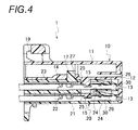
- Fig. 4 is a sectional side view of the connector in the completion state
- Fig. 5 is a plan view showing a state in which the connector of the embodiment is fitted into a mating connector
- Fig. 6 is a sectional view taken on arrow A-A of Fig. 5 .
- a female terminal 30 is contained inside each terminal containing chamber 24 of a connector housing 1A made of a resin molded article.
- the terminal containing chambers 24 respectively extend in the front and back direction of the connector housing 1A and are formed in two vertical stages, and each of the terminal containing chambers 24 is formed with a flexible lance 26 for retaining the female terminal 30 inserted from the back.
- the connector housing 1A in this embodiment is configured as an integrated article formed from two components constituting an upper housing (first housing) 10 and a lower housing (second housing) 20.
- the upper housing is integrally provided with a front end wall 12 of the connector housing defining the front end of each of the terminal containing chambers 24.
- the front side of the lower housing 20 is opened due to the lack of the front end wall 12.
- the upper housing 10 and the lower housing 20 are configured combinably in the upper and lower direction orthogonal to the front and back direction in the case of being united mutually, and the upper housing 10 is set in the upper side and the lower housing 20 is set in the lower side at the time of combination of them.
- the front end wall 12 is continuously and downwardly extended in the front end of an upper wall 11, and the front end wall 12 is formed with an insertion hole 13 into which the tip of a male terminal 55 of a mating connector 50 is inserted so as to be fitted into the female terminal 30 in the terminal containing chamber 24 at the time of being fitted into the mating connector 50 as shown in Fig. 6 .
- a locking arm 19 locked in a locking portion (not shown) of a mating connector housing 51 in the case of being fitted into the mating connector 50 is formed in the form of a cantilever arm in which a proximal end 19a as a fixed end is positioned in a position of the front end wall 12 and a distal end 19b as a free end is backward extended from the proximal end 19a.
- a lower stage wall 21, a middle stage wall 22 and an upper stage wall 23 are spaced in the upper and lower direction, and horizontal arrangement of the terminal containing chambers 24 of each stage is formed between the lower stage wall 21 and the middle stage wall 22 and between the middle stage wall 22 and the upper stage wall 23, respectively.
- each of the terminal containing chambers 24 is formed in the form in which the front end is opened, and the lance 26 having flexibility in the upper and lower direction by using an opening section on the front end as a through hole is molded inside each of the terminal containing chambers 24 as shown in Fig. 4 .
- the upper stage wall 23 and the middle stage wall 22 of the lower housing 20 are formed with openings 25 into which double locking portions 15 formed on a lower surface of the upper housing 10 are slidably inserted. Also, a position of the back side beyond a position in which the opening 25 of the upper stage wall 23 is formed is provided restricting convex portion convex portion (a restricting portion) 27 fitted into a restricting concave portion 17 formed on the lower surface of the upper housing 10.
- the upper housing 10 and the lower housing 20 are provided with locking claws 18 and locking convex portions 28 (locking mechanisms) for maintaining the united state by restricting both housings 10, 20 from separating in the upper or lower direction by mutually engaging in the case of properly combining both housings 10, 20 in the upper and lower direction.
- the upper housing 10 is assembled to the lower housing 20 from the upper side.
- the double locking portions 15 are maintained just before the double locking portions 15 enter the terminal containing chambers 24.
- the female terminal 30 is inserted into each of the terminal containing chambers 24 of the lower housing 20 from the back.
- the lance 26 pushed by the female terminal 30 flexes once and returns to the original state and thereby, the female terminal 30 is locked so as not to come out backward.
- the upper housing 10 is completely assembled to the lower housing 20.
- both housings 10, 20 are coupled so as not to move relatively in the front and back direction.
- the double locking portion 15 engages with the recess of the female terminal 30 and thereby, the female terminal 30 is doubly locked.
- the locking claws 18 engage with the locking convex portions 28 and thereby, the upper housing 10 is locked in the lower housing 20 so as not to be detached in the upper or lower direction. Consequently, the connector 1 is completed.
- the connector housing 1A is configured as the integrated article formed from two components constituting the upper housing 10 and the lower housing 20, and the upper housing 10 is formed with the front end wall 12 of the connector housing having the insertion holes 13 into which the male terminals 55 of the mating connector 50 are inserted and also, the lance 26 is formed in the lower housing 20 whose front end is opened due to the lack of the front end wall 12, so that the need to form the front end wall 12 of the connector housing with a through hole for forming a lance can be eliminated.
- the front end wall 12 of the connector housing has no through hole for forming the lance and thereby, the tip of the male terminal 55 at the time of connector fitting can be prevented from being inserted into the through hole by mistake, and connector fitting can become smooth.
- the upper housing 10 and the lower housing 20 in this case are combined and united in the upper and lower direction, and the upper housing 10 and the lower housing 20 are provided with the restricting portions (the restricting convex portion 27 and the restricting concave portion 17) which inhibit the relative displacement of both housings 10, 20 in the front and back direction when united, and the locking mechanisms (the locking claws 18 and the locking convex portions 28) for locking both housings 10, 20 in the upper and lower direction, so that the united state of the upper housing 10 and the lower housing 20 can be prevented from being displaced or loosened by a release manipulation etc. along the front and back direction in the case of releasing fitting into the mating connector 50, and though the two components are combined and united, integrity of the connector housing 1A can be maintained strongly.
- the restricting portions the restricting convex portion 27 and the restricting concave portion 17
- the locking mechanisms the locking claws 18 and the locking convex portions 28
- the female terminal 30 inserted into the terminal containing chamber 24 of the lower housing 20 from the back can be locked by the double locking portion 15 formed in the upper housing 10 together with the lance 26 formed in the terminal containing chamber 24, so that reliability of terminal holding can be improved.
- the upper housing 10 integrally provided with the front end wall of the connector housing is provided with the locking arm 19, so that the locking arm 19 can be formed longer with room from a position of the front end wall 12 of the connector housing.
- the locking arm 19 cannot be formed from the position of the front end wall 12 due to the lack of the front end wall 12 and therefore, the length of the locking arm cannot be ensured with room, but when the upper housing 10 is provided with the locking arm 19 as shown in the connector of the embodiment, the locking arm 19 can be formed with room for length, so that the locking arm 19 can be provided with sufficient flexibility.
Abstract
Description
- The present invention relates to a connector for containing a female terminal inside a connector housing and retaining the female terminal by a lance.
- In a connector for containing a female terminal inside a connector housing, generally, the female terminal inserted from the back is retained by a flexible lance formed inside a terminal containing chamber. The connector housing is manufactured by resin molding and in that case, molding of the lance becomes a problem. The normal lance is made of sections necessary to be molded from the back side and the front side of the connector housing by a metallic mold, and the section molded from the front side has a front end wall having an insertion hole (also called a pickup hole for a male terminal) of the male terminal of the mating connector side in the front end of the connector housing, so that the lance is molded by providing its front end wall with through holes for a mold. However, it is not desirable to remain many unnecessary holes which are not required functionally, that is, the through holes in the front end wall of the connector housing.
- Hence, for example,
Patent Reference 1 proposes and discloses a connector constructed so that a part including a front end wall of a connector housing having an insertion hole of a male terminal is constructed of a separate member and a lance of each terminal containing chamber can be molded from the front side of the housing in a state that the front end is opened without the front end wall. - As shown in
Fig. 7 , in this connector, aconnector housing 100 is divided into ahousing body 101 whose front end is opened as arecess 105, and a holdingmember 110 fitted into therecess 105 of the front end of thishousing body 101, and thehousing body 101 is formed with aterminal containing chamber 102 into which afemale terminal 130 is inserted from the back, and alance 103 for locking thefemale terminal 130 inserted from the back is formed inside theterminal containing chamber 102. In this case, the front end of theterminal containing chamber 102 is opened toward therecess 105 and thelance 103 is molded by using therecess 105 as molding space. Also, the holdingmember 110 constructing a front end wall of theconnector housing 100 is provided with aninsertion hole 112 for guiding the tip of amale terminal 140 so as to be fitted into thefemale terminal 130 by inserting themale terminal 140 of the mating connector side. - This connector is constructed so that the
connector housing 100 is assembled by fitting the holdingmember 110 into therecess 105 of the front end of thehousing body 101 from the front and engaging the holdingmember 110 and thefemale terminal 130 is inserted into each of theterminal containing chambers 102 of itsconnector housing 100 from the back and each of thefemale terminals 130 is retained by thelance 103. -
- Patent Reference 1:
JP-A-2006-302752 - Incidentally, in the connector described in
Patent Reference 1 shown inFig. 7 , the front end wall of theconnector housing 100 is formed as the holdingmember 110 separate from thehousing body 101, so that the connector can obtain an advantage of eliminating the need to provide the front end wall (the holding member 110) with a through hole of thelance 103, but adopts a configuration in which the holdingmember 110 is attached and engaged to therecess 105 of the front end of thehousing body 101 from the front side, with the result that by an operation etc. in the case of releasing fitting into the mating connector, a force in a direction detached from thehousing body 101 acts on the holdingmember 110 and this may displace or loosen a united state of the holdingmember 110 and thehousing body 101. - In view of the circumstances described above, an object of the invention is to provide a connector in which a front end wall of a connector housing does not need to be formed with unnecessary holes (a through hole for forming a lance) and also the connector housing is configured as two components, a united state of the connector housing can be prevented from being displaced or loosened to configure the connector housing with high integrity.
- In order to solve the problem described above, a first invention is a connector in which plural terminal containing chambers extending in the front and back direction are formed inside a connector housing made of a resin molded article and a female terminal inserted into each of the terminal containing chambers from the back is retained by a flexible lance formed inside the terminal containing chamber, and the connector housing is configured as an integrated article formed from two components constituting a first housing which is integrally provided with a front end wall of the connector housing defining the front end of each of the terminal containing chambers, and a second housing, the front side of which is opened due to the lack of the front end wall, and the front end wall of the first housing is formed with an insertion hole into which the tip of a male terminal of a mating connector is inserted so as to be fitted into the female terminal of the inside of the terminal containing chamber at the time of being fitted into the mating connector, and the second housing is formed with the terminal containing chamber in a state that the front end is opened, and is also disposed with the lance which is molded by using an opening section on the front end of the second housing as a through hole, and the first housing and the second housing can be combined in the upper and lower direction orthogonal to the front and back direction in the case of being united mutually, and the first housing and the second housing are provided restricting convex portion which inhibits the relative displacement of both housings in the front and back direction when united, and a locking mechanism for maintaining the united state by restricting both housings from separating in the upper or lower direction.
- A second invention is the connector of the first invention, and the first housing is provided with a double locking portion for doubly locking the female terminal together with the lance in the case of being combined with the second housing.
- A third invention is the connector of the first or second invention, and the first housing is an upper housing set in an upper side at the time of combination and the second housing is a lower housing set in a lower side at the time of combination, and the first housing is provided with a locking arm locked in a locking portion of a mating connector housing in the case of being fitted into the mating connector.
- According to the first invention, the connector housing is configured as the integrated article formed from two components constituting the first housing and the second housing, and the first housing is formed with the front end wall of the connector housing having the insertion holes into which the male terminals of the mating connector are inserted and also, the lance is formed in the second housing whose front end is opened due to the lack of the front end wall, so that the need to form the front end wall of the connector housing with a through hole for forming a lance can be eliminated. Therefore, a situation in which many through holes are left in the front end wall of the connector housing due to an increase in the number of terminals per area of the front end wall of the connector housing with miniaturization of the connector can be avoided. Also, the front end wall of the connector housing has no through hole for forming the lance and thereby, the tip of the male terminal at the time of connector fitting can be prevented from being inserted into the through hole by mistake, and connector fitting can become smooth.
- Also, the first housing and the second housing in this case are combined and united in the upper and lower direction, and the first housing and the second housing are provided with the restricting portion which inhibits the relative displacement of both housings in the front and back direction when united, and the locking mechanism for locking both housings in the upper and lower direction, so that the united state of the first housing and the second housing can be prevented from being displaced or loosened by a release manipulation etc. along the front and back direction in the case of releasing fitting into the mating connector, and though the two components are combined and united, integrity of the connector housing can be maintained strongly.
- According to the second invention, the female terminal inserted into the terminal containing chamber of the second housing from the back can be locked by the double locking portion formed in the first housing together with the lance formed in the terminal containing chamber, so that reliability of terminal holding can be improved.
- According to the third invention, the first housing integrally provided with the front end wall of the connector housing has the locking arm, so that the locking arm can be formed longer with room from a position of the front end wall of the connector housing. By the way, when the second housing without the front end wall is provided with the locking arm, the locking arm cannot be formed from the position of the front end wall due to the lack of the front end wall and therefore, the length of the locking arm cannot be ensured with room, but when the first housing has the locking arm as shown in the third invention, the locking arm can be formed with room for length. Therefore, the locking arm can be provided with sufficient flexibility.
-
- [
Fig. 1] Fig. 1 is an appearance perspective view showing an upper housing (first housing) which is a component of a connector according to an embodiment of the invention. - [
Fig. 2] Fig. 2 is an appearance perspective view showing a lower housing (second housing) which is a component of the same connector. - [
Fig. 3] Fig. 3 is an appearance perspective view showing a completion state of the same connector. - [
Fig. 4] Fig. 4 is a sectional side view of the connector in the completion state ofFig. 3 . - [
Fig. 5] Fig. 5 is a plan view showing a state in which the same connector is fitted into a mating connector. - [
Fig. 6] Fig. 6 is a sectional view taken on arrow A-A ofFig. 5 . - [
Fig. 7] Fig. 7 is a sectional side view showing a configuration of a conventional connector. - An embodiment of the invention will hereinafter be described with reference to the drawings.
-
Fig. 1 is an appearance perspective view showing an upper housing (first housing) which is a component of a connector of the embodiment, andFig. 2 is an appearance perspective view showing a lower housing (second housing), andFig. 3 is an appearance perspective view showing a completion state of the connector, andFig. 4 is a sectional side view of the connector in the completion state, andFig. 5 is a plan view showing a state in which the connector of the embodiment is fitted into a mating connector, andFig. 6 is a sectional view taken on arrow A-A ofFig. 5 . - As shown in
Figs. 3 and4 , in thisconnector 1, afemale terminal 30 is contained inside eachterminal containing chamber 24 of aconnector housing 1A made of a resin molded article. Theterminal containing chambers 24 respectively extend in the front and back direction of theconnector housing 1A and are formed in two vertical stages, and each of theterminal containing chambers 24 is formed with aflexible lance 26 for retaining thefemale terminal 30 inserted from the back. - The
connector housing 1A in this embodiment is configured as an integrated article formed from two components constituting an upper housing (first housing) 10 and a lower housing (second housing) 20. The upper housing is integrally provided with afront end wall 12 of the connector housing defining the front end of each of theterminal containing chambers 24. The front side of thelower housing 20 is opened due to the lack of thefront end wall 12. Theupper housing 10 and thelower housing 20 are configured combinably in the upper and lower direction orthogonal to the front and back direction in the case of being united mutually, and theupper housing 10 is set in the upper side and thelower housing 20 is set in the lower side at the time of combination of them. - In the
upper housing 10 shown inFig. 1 , thefront end wall 12 is continuously and downwardly extended in the front end of anupper wall 11, and thefront end wall 12 is formed with aninsertion hole 13 into which the tip of amale terminal 55 of amating connector 50 is inserted so as to be fitted into thefemale terminal 30 in theterminal containing chamber 24 at the time of being fitted into themating connector 50 as shown inFig. 6 . Also, on an upper surface of theupper wall 11 of theupper housing 10, alocking arm 19 locked in a locking portion (not shown) of amating connector housing 51 in the case of being fitted into themating connector 50 is formed in the form of a cantilever arm in which aproximal end 19a as a fixed end is positioned in a position of thefront end wall 12 and adistal end 19b as a free end is backward extended from theproximal end 19a. - Also, in the
lower housing 20 shown inFig. 2 , alower stage wall 21, amiddle stage wall 22 and anupper stage wall 23 are spaced in the upper and lower direction, and horizontal arrangement of theterminal containing chambers 24 of each stage is formed between thelower stage wall 21 and themiddle stage wall 22 and between themiddle stage wall 22 and theupper stage wall 23, respectively. By providing thefront end wall 12 on theupper housing 10, each of theterminal containing chambers 24 is formed in the form in which the front end is opened, and thelance 26 having flexibility in the upper and lower direction by using an opening section on the front end as a through hole is molded inside each of theterminal containing chambers 24 as shown inFig. 4 . - Also, as shown in
Fig. 4 , theupper stage wall 23 and themiddle stage wall 22 of thelower housing 20 are formed withopenings 25 into which double lockingportions 15 formed on a lower surface of theupper housing 10 are slidably inserted. Also, a position of the back side beyond a position in which the opening 25 of theupper stage wall 23 is formed is provided restricting convex portion convex portion (a restricting portion) 27 fitted into a restrictingconcave portion 17 formed on the lower surface of theupper housing 10. - Then, in a united state of the
upper housing 10 and thelower housing 20, thedouble locking portion 15 of theupper housing 10 entering the inside of theterminal containing chamber 24 through the opening 25 of thelower housing 20 engages with a recess of thefemale terminal 30 and thereby, thefemale terminal 30 is doubly locked in addition to locking by thelance 26. Also, in the united state of theupper housing 10 and thelower housing 20, the restricting convexportion 27 of thelower housing 20 is fitted into the restrictingconcave portion 17 of theupper housing 10 and thereby, relative displacement of bothhousings - Also, the
upper housing 10 and thelower housing 20 are provided withlocking claws 18 and locking convex portions 28 (locking mechanisms) for maintaining the united state by restricting bothhousings housings - When this
connector 1 is assembled, theupper housing 10 is assembled to thelower housing 20 from the upper side. When theupper housing 10 is assembled halfway, thedouble locking portions 15 are maintained just before thedouble locking portions 15 enter theterminal containing chambers 24. In this state, thefemale terminal 30 is inserted into each of theterminal containing chambers 24 of thelower housing 20 from the back. When thefemale terminal 30 is inserted deeply, thelance 26 pushed by the female terminal 30 flexes once and returns to the original state and thereby, thefemale terminal 30 is locked so as not to come out backward. In this state, theupper housing 10 is completely assembled to thelower housing 20. Then, the restrictingconvex portion 27 is fitted into the restrictingconcave portion 17 and thereby, bothhousings double locking portion 15 engages with the recess of thefemale terminal 30 and thereby, thefemale terminal 30 is doubly locked. Also, thelocking claws 18 engage with the lockingconvex portions 28 and thereby, theupper housing 10 is locked in thelower housing 20 so as not to be detached in the upper or lower direction. Consequently, theconnector 1 is completed. - When this
connector 1 is connected to themating connector 50 as shown inFigs. 5 and6 , theconnector housing 1A is fitted into a fittingconcave portion 52 of theconnector housing 51 of themating connector 50. Then, the tips of themale terminals 55 maintained in a back wall portion of themating connector housing 51 are respectively inserted into the insertion holes 13 of thefront end wall 12 of theupper housing 10 constructing theconnector housing 1A and are fitted into thefemale terminals 30 maintained inside theterminal containing chambers 24. Consequently, connection between theconnectors - According to this
connector 1 as described above, theconnector housing 1A is configured as the integrated article formed from two components constituting theupper housing 10 and thelower housing 20, and theupper housing 10 is formed with thefront end wall 12 of the connector housing having the insertion holes 13 into which themale terminals 55 of themating connector 50 are inserted and also, thelance 26 is formed in thelower housing 20 whose front end is opened due to the lack of thefront end wall 12, so that the need to form thefront end wall 12 of the connector housing with a through hole for forming a lance can be eliminated. Therefore, a situation in which many through holes are remained in thefront end wall 12 of the connector housing due to an increase in the number of terminals per area of thefront end wall 12 of theconnector housing 1A with miniaturization of theconnector 1 can be avoided. Also, thefront end wall 12 of the connector housing has no through hole for forming the lance and thereby, the tip of themale terminal 55 at the time of connector fitting can be prevented from being inserted into the through hole by mistake, and connector fitting can become smooth. - Also, the
upper housing 10 and thelower housing 20 in this case are combined and united in the upper and lower direction, and theupper housing 10 and thelower housing 20 are provided with the restricting portions (the restrictingconvex portion 27 and the restricting concave portion 17) which inhibit the relative displacement of bothhousings claws 18 and the locking convex portions 28) for locking bothhousings upper housing 10 and thelower housing 20 can be prevented from being displaced or loosened by a release manipulation etc. along the front and back direction in the case of releasing fitting into themating connector 50, and though the two components are combined and united, integrity of theconnector housing 1A can be maintained strongly. - Also, the
female terminal 30 inserted into theterminal containing chamber 24 of thelower housing 20 from the back can be locked by thedouble locking portion 15 formed in theupper housing 10 together with thelance 26 formed in theterminal containing chamber 24, so that reliability of terminal holding can be improved. - Also, the
upper housing 10 integrally provided with the front end wall of the connector housing is provided with the lockingarm 19, so that the lockingarm 19 can be formed longer with room from a position of thefront end wall 12 of the connector housing. By the way, when thelower housing 20 without thefront end wall 12 is provided with the lockingarm 19, the locking arm cannot be formed from the position of thefront end wall 12 due to the lack of thefront end wall 12 and therefore, the length of the locking arm cannot be ensured with room, but when theupper housing 10 is provided with the lockingarm 19 as shown in the connector of the embodiment, the lockingarm 19 can be formed with room for length, so that the lockingarm 19 can be provided with sufficient flexibility. - The invention has been described in detail with reference to the specific embodiment, but it is apparent to those skilled in the art that various changes or modifications can be made without departing from the spirit and scope of the invention.
- The present application is based on Japanese patent application (patent application No.
2010-016616) filed on January 28, 2010 -
- 1
- CONNECTOR
- 1A
- CONNECTOR HOUSING
- 10
- UPPER HOUSING (FIRST HOUSING)
- 12
- FRONT END WALL
- 13
- INSERTION HOLE
- 15
- DOUBLE LOCKING PORTION
- 17
- RESTRICTING CONCAVE PORTION (RESTRICTING PORTION)
- 18
- LOCKING CLAW (LOCKING MECHANISM)
- 19
- LOCKING ARM
- 20
- LOWER HOUSING (SECOND HOUSING)
- 24
- TERMINAL CONTAINING CHAMBER
- 26
- LANCE
- 25
- OPENING
- 27
- RESTRICTING CONVEX PORTION (RESTRICTING PORTION)
- 28
- LOCKING CONVEX PORTION (LOCKING MECHANISM)
- 30
- FEMALE TERMINAL
- 50
- MATING CONNECTOR
- 55
- MALE TERMINAL
Claims (3)
- A connector comprising:a connector housing made of a resin molded article; andplural terminal containing chambers that extend in the front and back direction and are formed inside the connector housing, female terminals being inserted into the terminal containing chambers from the back and retained by flexible lances formed inside the terminal containing chambers,wherein the connector housing is configured as an integrated article formed from two components constituting a first housing and a second housing;wherein the first housing is integrally provided with a front end wall of the connector housing defining a front end of each of the terminal containing chambers, and the front side of the second housing is opened due to the lack of the front end wall;wherein the front end wall of the first housing has insertion holes into which tips of male terminals of a mating connector are inserted so as to be fitted into the female terminals in the terminal containing chambers at the time of being fitted into the mating connector;wherein the terminal containing chambers are formed in the second housing in a state that the front end of each of the terminal containing chambers is opened, and the lances are formed so as to be molded by using opening section on the front end of each of the terminal containing chambers as a through hole; andwherein the first housing and the second housing are able to be combined in the upper and lower direction orthogonal to the front and back direction in the case of being united mutually, and the first housing and the second housing are provided with a restricting convex portion which inhibits a relative displacement of the first and second housings in the front and back direction when united and a locking mechanism for maintaining the united state by restricting the first and second housings from separating in the upper or lower direction.
- The connector according to claim 1, wherein the first housing is provided with double locking portions for doubly locking the female terminals together with the lances in the case of being combined with the second housing.
- The connector according to claim 1 or 2, wherein the first housing is an upper housing arranged in an upper side at the time of an assemble and the second housing is a lower housing arranged in a lower side at the time of the assemble: and
wherein the first housing is provided with a locking arm locked in a locking portion of a mating connector housing in the case of being fitted into the mating connector.
Applications Claiming Priority (2)
| Application Number | Priority Date | Filing Date | Title |
|---|---|---|---|
| JP2010016616A JP5421809B2 (en) | 2010-01-28 | 2010-01-28 | connector |
| PCT/JP2011/051631 WO2011093390A1 (en) | 2010-01-28 | 2011-01-27 | Connector |
Publications (2)
| Publication Number | Publication Date |
|---|---|
| EP2530788A1 true EP2530788A1 (en) | 2012-12-05 |
| EP2530788A4 EP2530788A4 (en) | 2013-06-26 |
Family
ID=44319373
Family Applications (1)
| Application Number | Title | Priority Date | Filing Date |
|---|---|---|---|
| EP20110737101 Withdrawn EP2530788A4 (en) | 2010-01-28 | 2011-01-27 | Connector |
Country Status (5)
| Country | Link |
|---|---|
| US (1) | US8747169B2 (en) |
| EP (1) | EP2530788A4 (en) |
| JP (1) | JP5421809B2 (en) |
| CN (1) | CN102725916A (en) |
| WO (1) | WO2011093390A1 (en) |
Cited By (1)
| Publication number | Priority date | Publication date | Assignee | Title |
|---|---|---|---|---|
| EP2846417A1 (en) * | 2012-12-13 | 2015-03-11 | Dai-Ichi Seiko Co., Ltd. | Electric connector and terminal used therefor |
Families Citing this family (9)
| Publication number | Priority date | Publication date | Assignee | Title |
|---|---|---|---|---|
| JP6088345B2 (en) * | 2013-05-07 | 2017-03-01 | 矢崎総業株式会社 | connector |
| JP5999510B2 (en) * | 2013-05-30 | 2016-09-28 | 住友電装株式会社 | Female terminal fitting and manufacturing method thereof |
| JP6393301B2 (en) * | 2016-10-11 | 2018-09-19 | 株式会社オートネットワーク技術研究所 | connector |
| JP2019050169A (en) * | 2017-09-12 | 2019-03-28 | 住友電装株式会社 | connector |
| JP6626870B2 (en) * | 2017-10-05 | 2019-12-25 | 矢崎総業株式会社 | connector |
| WO2019188738A1 (en) * | 2018-03-30 | 2019-10-03 | 株式会社オートネットワーク技術研究所 | Connector |
| KR20220049945A (en) * | 2020-10-15 | 2022-04-22 | 현대자동차주식회사 | Connector assembly |
| KR20220059799A (en) | 2020-11-03 | 2022-05-10 | 현대자동차주식회사 | Connector assembly and manufacturing method of the same |
| JP2022113255A (en) * | 2021-01-25 | 2022-08-04 | 住友電装株式会社 | connector |
Citations (5)
| Publication number | Priority date | Publication date | Assignee | Title |
|---|---|---|---|---|
| EP0929124A1 (en) * | 1998-01-09 | 1999-07-14 | Sumitomo Wiring Systems, Ltd. | Electrical connector |
| GB2432466A (en) * | 2005-11-22 | 2007-05-23 | Yazaki Corp | Electrical connector housing for retaining terminals |
| WO2008023009A1 (en) * | 2006-08-21 | 2008-02-28 | Fci | Electrical connector and housing thereof |
| US20080119084A1 (en) * | 2006-11-20 | 2008-05-22 | Tyco Electronics Corporation | Stacked electrical connector with terminal assurance mechanism |
| JP2010009801A (en) * | 2008-06-25 | 2010-01-14 | Yazaki Corp | Connector |
Family Cites Families (12)
| Publication number | Priority date | Publication date | Assignee | Title |
|---|---|---|---|---|
| JPH1021986A (en) * | 1996-07-03 | 1998-01-23 | Sumitomo Wiring Syst Ltd | Block connector |
| JP3330506B2 (en) * | 1997-03-10 | 2002-09-30 | 矢崎総業株式会社 | connector |
| JP3330529B2 (en) * | 1997-10-03 | 2002-09-30 | 矢崎総業株式会社 | Coupling connector |
| JP3436113B2 (en) * | 1998-01-27 | 2003-08-11 | 住友電装株式会社 | connector |
| JP2000156257A (en) * | 1998-11-17 | 2000-06-06 | Sumitomo Wiring Syst Ltd | Pressure contact connector |
| JP2006302752A (en) * | 2005-04-22 | 2006-11-02 | Tyco Electronics Amp Kk | Electric connector |
| JP2007095360A (en) * | 2005-09-27 | 2007-04-12 | Yazaki Corp | Integrated connector |
| JP4730237B2 (en) * | 2006-07-20 | 2011-07-20 | 住友電装株式会社 | connector |
| JP2008130561A (en) * | 2006-11-20 | 2008-06-05 | Tyco Electronics Corp | Electric connector |
| JP4926836B2 (en) * | 2007-06-05 | 2012-05-09 | 矢崎総業株式会社 | connector |
| US7780484B2 (en) * | 2008-06-13 | 2010-08-24 | Tyco Electronics Corporation | Electrical connector having alternative inner housings |
| JP5078779B2 (en) | 2008-07-03 | 2012-11-21 | キヤノン株式会社 | Imaging device |
-
2010
- 2010-01-28 JP JP2010016616A patent/JP5421809B2/en not_active Expired - Fee Related
-
2011
- 2011-01-27 WO PCT/JP2011/051631 patent/WO2011093390A1/en active Application Filing
- 2011-01-27 EP EP20110737101 patent/EP2530788A4/en not_active Withdrawn
- 2011-01-27 CN CN2011800075695A patent/CN102725916A/en active Pending
-
2012
- 2012-07-27 US US13/559,751 patent/US8747169B2/en active Active
Patent Citations (5)
| Publication number | Priority date | Publication date | Assignee | Title |
|---|---|---|---|---|
| EP0929124A1 (en) * | 1998-01-09 | 1999-07-14 | Sumitomo Wiring Systems, Ltd. | Electrical connector |
| GB2432466A (en) * | 2005-11-22 | 2007-05-23 | Yazaki Corp | Electrical connector housing for retaining terminals |
| WO2008023009A1 (en) * | 2006-08-21 | 2008-02-28 | Fci | Electrical connector and housing thereof |
| US20080119084A1 (en) * | 2006-11-20 | 2008-05-22 | Tyco Electronics Corporation | Stacked electrical connector with terminal assurance mechanism |
| JP2010009801A (en) * | 2008-06-25 | 2010-01-14 | Yazaki Corp | Connector |
Non-Patent Citations (1)
| Title |
|---|
| See also references of WO2011093390A1 * |
Cited By (2)
| Publication number | Priority date | Publication date | Assignee | Title |
|---|---|---|---|---|
| EP2846417A1 (en) * | 2012-12-13 | 2015-03-11 | Dai-Ichi Seiko Co., Ltd. | Electric connector and terminal used therefor |
| US9070999B2 (en) | 2012-12-13 | 2015-06-30 | Dai-Ichi Seiko Co., Ltd. | Electric connector and terminal used therefor |
Also Published As
| Publication number | Publication date |
|---|---|
| CN102725916A (en) | 2012-10-10 |
| WO2011093390A1 (en) | 2011-08-04 |
| JP2011154941A (en) | 2011-08-11 |
| US8747169B2 (en) | 2014-06-10 |
| EP2530788A4 (en) | 2013-06-26 |
| US20120295491A1 (en) | 2012-11-22 |
| JP5421809B2 (en) | 2014-02-19 |
Similar Documents
| Publication | Publication Date | Title |
|---|---|---|
| US8747169B2 (en) | Connector | |
| US5980318A (en) | Connector with a flexible beam for holding a terminal down and in position | |
| TWI325657B (en) | Electrical connector | |
| US9231342B2 (en) | Connector | |
| EP2355255B1 (en) | Terminal fitting and connector provided therewith | |
| JP6138428B2 (en) | connector | |
| JPH09330757A (en) | Connector | |
| JP4062250B2 (en) | connector | |
| JP3969161B2 (en) | connector | |
| JP2005327617A (en) | Connector | |
| JPH09283203A (en) | Electric connector having retainer | |
| JP3765386B2 (en) | connector | |
| JP2014096227A (en) | Electric connector | |
| JP4655997B2 (en) | connector | |
| TW201236522A (en) | Connector and assembly jig for connector | |
| JP3906761B2 (en) | connector | |
| JP2006107820A (en) | Connector | |
| EP3731348A1 (en) | Connector housing | |
| JP3754642B2 (en) | connector | |
| US10923849B2 (en) | Connector | |
| JP5183315B2 (en) | connector | |
| JP3755644B2 (en) | connector | |
| US20230170642A1 (en) | Connector | |
| US20230402789A1 (en) | Connector, Mating Connector and Connector Assembly | |
| JP2010140806A (en) | Connector |
Legal Events
| Date | Code | Title | Description |
|---|---|---|---|
| PUAI | Public reference made under article 153(3) epc to a published international application that has entered the european phase |
Free format text: ORIGINAL CODE: 0009012 |
|
| 17P | Request for examination filed |
Effective date: 20120727 |
|
| AK | Designated contracting states |
Kind code of ref document: A1 Designated state(s): AL AT BE BG CH CY CZ DE DK EE ES FI FR GB GR HR HU IE IS IT LI LT LU LV MC MK MT NL NO PL PT RO RS SE SI SK SM TR |
|
| DAX | Request for extension of the european patent (deleted) | ||
| A4 | Supplementary search report drawn up and despatched |
Effective date: 20130528 |
|
| RIC1 | Information provided on ipc code assigned before grant |
Ipc: H01R 13/514 20060101AFI20130522BHEP Ipc: H01R 13/42 20060101ALI20130522BHEP |
|
| 17Q | First examination report despatched |
Effective date: 20150316 |
|
| STAA | Information on the status of an ep patent application or granted ep patent |
Free format text: STATUS: THE APPLICATION IS DEEMED TO BE WITHDRAWN |
|
| 18D | Application deemed to be withdrawn |
Effective date: 20150728 |