EP2530294A1 - Double-walled fuel supply line element - Google Patents
Double-walled fuel supply line element Download PDFInfo
- Publication number
- EP2530294A1 EP2530294A1 EP11168267A EP11168267A EP2530294A1 EP 2530294 A1 EP2530294 A1 EP 2530294A1 EP 11168267 A EP11168267 A EP 11168267A EP 11168267 A EP11168267 A EP 11168267A EP 2530294 A1 EP2530294 A1 EP 2530294A1
- Authority
- EP
- European Patent Office
- Prior art keywords
- line element
- fuel supply
- double
- supply line
- walled fuel
- Prior art date
- Legal status (The legal status is an assumption and is not a legal conclusion. Google has not performed a legal analysis and makes no representation as to the accuracy of the status listed.)
- Granted
Links
Images


Classifications
-
- F—MECHANICAL ENGINEERING; LIGHTING; HEATING; WEAPONS; BLASTING
- F02—COMBUSTION ENGINES; HOT-GAS OR COMBUSTION-PRODUCT ENGINE PLANTS
- F02M—SUPPLYING COMBUSTION ENGINES IN GENERAL WITH COMBUSTIBLE MIXTURES OR CONSTITUENTS THEREOF
- F02M55/00—Fuel-injection apparatus characterised by their fuel conduits or their venting means; Arrangements of conduits between fuel tank and pump F02M37/00
- F02M55/02—Conduits between injection pumps and injectors, e.g. conduits between pump and common-rail or conduits between common-rail and injectors
-
- F—MECHANICAL ENGINEERING; LIGHTING; HEATING; WEAPONS; BLASTING
- F02—COMBUSTION ENGINES; HOT-GAS OR COMBUSTION-PRODUCT ENGINE PLANTS
- F02M—SUPPLYING COMBUSTION ENGINES IN GENERAL WITH COMBUSTIBLE MIXTURES OR CONSTITUENTS THEREOF
- F02M55/00—Fuel-injection apparatus characterised by their fuel conduits or their venting means; Arrangements of conduits between fuel tank and pump F02M37/00
-
- B—PERFORMING OPERATIONS; TRANSPORTING
- B60—VEHICLES IN GENERAL
- B60K—ARRANGEMENT OR MOUNTING OF PROPULSION UNITS OR OF TRANSMISSIONS IN VEHICLES; ARRANGEMENT OR MOUNTING OF PLURAL DIVERSE PRIME-MOVERS IN VEHICLES; AUXILIARY DRIVES FOR VEHICLES; INSTRUMENTATION OR DASHBOARDS FOR VEHICLES; ARRANGEMENTS IN CONNECTION WITH COOLING, AIR INTAKE, GAS EXHAUST OR FUEL SUPPLY OF PROPULSION UNITS IN VEHICLES
- B60K15/00—Arrangement in connection with fuel supply of combustion engines or other fuel consuming energy converters, e.g. fuel cells; Mounting or construction of fuel tanks
- B60K15/01—Arrangement of fuel conduits
-
- F—MECHANICAL ENGINEERING; LIGHTING; HEATING; WEAPONS; BLASTING
- F02—COMBUSTION ENGINES; HOT-GAS OR COMBUSTION-PRODUCT ENGINE PLANTS
- F02D—CONTROLLING COMBUSTION ENGINES
- F02D19/00—Controlling engines characterised by their use of non-liquid fuels, pluralities of fuels, or non-fuel substances added to the combustible mixtures
- F02D19/06—Controlling engines characterised by their use of non-liquid fuels, pluralities of fuels, or non-fuel substances added to the combustible mixtures peculiar to engines working with pluralities of fuels, e.g. alternatively with light and heavy fuel oil, other than engines indifferent to the fuel consumed
-
- F—MECHANICAL ENGINEERING; LIGHTING; HEATING; WEAPONS; BLASTING
- F02—COMBUSTION ENGINES; HOT-GAS OR COMBUSTION-PRODUCT ENGINE PLANTS
- F02M—SUPPLYING COMBUSTION ENGINES IN GENERAL WITH COMBUSTIBLE MIXTURES OR CONSTITUENTS THEREOF
- F02M21/00—Apparatus for supplying engines with non-liquid fuels, e.g. gaseous fuels stored in liquid form
- F02M21/02—Apparatus for supplying engines with non-liquid fuels, e.g. gaseous fuels stored in liquid form for gaseous fuels
- F02M21/0218—Details on the gaseous fuel supply system, e.g. tanks, valves, pipes, pumps, rails, injectors or mixers
- F02M21/0245—High pressure fuel supply systems; Rails; Pumps; Arrangement of valves
-
- F—MECHANICAL ENGINEERING; LIGHTING; HEATING; WEAPONS; BLASTING
- F02—COMBUSTION ENGINES; HOT-GAS OR COMBUSTION-PRODUCT ENGINE PLANTS
- F02M—SUPPLYING COMBUSTION ENGINES IN GENERAL WITH COMBUSTIBLE MIXTURES OR CONSTITUENTS THEREOF
- F02M21/00—Apparatus for supplying engines with non-liquid fuels, e.g. gaseous fuels stored in liquid form
- F02M21/02—Apparatus for supplying engines with non-liquid fuels, e.g. gaseous fuels stored in liquid form for gaseous fuels
- F02M21/0218—Details on the gaseous fuel supply system, e.g. tanks, valves, pipes, pumps, rails, injectors or mixers
- F02M21/0293—Safety devices; Fail-safe measures
-
- F—MECHANICAL ENGINEERING; LIGHTING; HEATING; WEAPONS; BLASTING
- F02—COMBUSTION ENGINES; HOT-GAS OR COMBUSTION-PRODUCT ENGINE PLANTS
- F02M—SUPPLYING COMBUSTION ENGINES IN GENERAL WITH COMBUSTIBLE MIXTURES OR CONSTITUENTS THEREOF
- F02M37/00—Apparatus or systems for feeding liquid fuel from storage containers to carburettors or fuel-injection apparatus; Arrangements for purifying liquid fuel specially adapted for, or arranged on, internal-combustion engines
-
- F—MECHANICAL ENGINEERING; LIGHTING; HEATING; WEAPONS; BLASTING
- F02—COMBUSTION ENGINES; HOT-GAS OR COMBUSTION-PRODUCT ENGINE PLANTS
- F02M—SUPPLYING COMBUSTION ENGINES IN GENERAL WITH COMBUSTIBLE MIXTURES OR CONSTITUENTS THEREOF
- F02M43/00—Fuel-injection apparatus operating simultaneously on two or more fuels, or on a liquid fuel and another liquid, e.g. the other liquid being an anti-knock additive
-
- F—MECHANICAL ENGINEERING; LIGHTING; HEATING; WEAPONS; BLASTING
- F02—COMBUSTION ENGINES; HOT-GAS OR COMBUSTION-PRODUCT ENGINE PLANTS
- F02M—SUPPLYING COMBUSTION ENGINES IN GENERAL WITH COMBUSTIBLE MIXTURES OR CONSTITUENTS THEREOF
- F02M55/00—Fuel-injection apparatus characterised by their fuel conduits or their venting means; Arrangements of conduits between fuel tank and pump F02M37/00
- F02M55/002—Arrangement of leakage or drain conduits in or from injectors
-
- F—MECHANICAL ENGINEERING; LIGHTING; HEATING; WEAPONS; BLASTING
- F02—COMBUSTION ENGINES; HOT-GAS OR COMBUSTION-PRODUCT ENGINE PLANTS
- F02M—SUPPLYING COMBUSTION ENGINES IN GENERAL WITH COMBUSTIBLE MIXTURES OR CONSTITUENTS THEREOF
- F02M63/00—Other fuel-injection apparatus having pertinent characteristics not provided for in groups F02M39/00 - F02M57/00 or F02M67/00; Details, component parts, or accessories of fuel-injection apparatus, not provided for in, or of interest apart from, the apparatus of groups F02M39/00 - F02M61/00 or F02M67/00; Combination of fuel pump with other devices, e.g. lubricating oil pump
-
- F—MECHANICAL ENGINEERING; LIGHTING; HEATING; WEAPONS; BLASTING
- F02—COMBUSTION ENGINES; HOT-GAS OR COMBUSTION-PRODUCT ENGINE PLANTS
- F02M—SUPPLYING COMBUSTION ENGINES IN GENERAL WITH COMBUSTIBLE MIXTURES OR CONSTITUENTS THEREOF
- F02M69/00—Low-pressure fuel-injection apparatus ; Apparatus with both continuous and intermittent injection; Apparatus injecting different types of fuel
- F02M69/46—Details, component parts or accessories not provided for in, or of interest apart from, the apparatus covered by groups F02M69/02 - F02M69/44
- F02M69/462—Arrangement of fuel conduits, e.g. with valves for maintaining pressure in the pipes after the engine being shut-down
- F02M69/465—Arrangement of fuel conduits, e.g. with valves for maintaining pressure in the pipes after the engine being shut-down of fuel rails
-
- F—MECHANICAL ENGINEERING; LIGHTING; HEATING; WEAPONS; BLASTING
- F16—ENGINEERING ELEMENTS AND UNITS; GENERAL MEASURES FOR PRODUCING AND MAINTAINING EFFECTIVE FUNCTIONING OF MACHINES OR INSTALLATIONS; THERMAL INSULATION IN GENERAL
- F16L—PIPES; JOINTS OR FITTINGS FOR PIPES; SUPPORTS FOR PIPES, CABLES OR PROTECTIVE TUBING; MEANS FOR THERMAL INSULATION IN GENERAL
- F16L39/00—Joints or fittings for double-walled or multi-channel pipes or pipe assemblies
- F16L39/005—Joints or fittings for double-walled or multi-channel pipes or pipe assemblies for concentric pipes
-
- F—MECHANICAL ENGINEERING; LIGHTING; HEATING; WEAPONS; BLASTING
- F16—ENGINEERING ELEMENTS AND UNITS; GENERAL MEASURES FOR PRODUCING AND MAINTAINING EFFECTIVE FUNCTIONING OF MACHINES OR INSTALLATIONS; THERMAL INSULATION IN GENERAL
- F16L—PIPES; JOINTS OR FITTINGS FOR PIPES; SUPPORTS FOR PIPES, CABLES OR PROTECTIVE TUBING; MEANS FOR THERMAL INSULATION IN GENERAL
- F16L41/00—Branching pipes; Joining pipes to walls
- F16L41/02—Branch units, e.g. made in one piece, welded, riveted
- F16L41/021—T- or cross-pieces
-
- F—MECHANICAL ENGINEERING; LIGHTING; HEATING; WEAPONS; BLASTING
- F16—ENGINEERING ELEMENTS AND UNITS; GENERAL MEASURES FOR PRODUCING AND MAINTAINING EFFECTIVE FUNCTIONING OF MACHINES OR INSTALLATIONS; THERMAL INSULATION IN GENERAL
- F16L—PIPES; JOINTS OR FITTINGS FOR PIPES; SUPPORTS FOR PIPES, CABLES OR PROTECTIVE TUBING; MEANS FOR THERMAL INSULATION IN GENERAL
- F16L9/00—Rigid pipes
- F16L9/18—Double-walled pipes; Multi-channel pipes or pipe assemblies
- F16L9/19—Multi-channel pipes or pipe assemblies
-
- F—MECHANICAL ENGINEERING; LIGHTING; HEATING; WEAPONS; BLASTING
- F02—COMBUSTION ENGINES; HOT-GAS OR COMBUSTION-PRODUCT ENGINE PLANTS
- F02D—CONTROLLING COMBUSTION ENGINES
- F02D19/00—Controlling engines characterised by their use of non-liquid fuels, pluralities of fuels, or non-fuel substances added to the combustible mixtures
- F02D19/06—Controlling engines characterised by their use of non-liquid fuels, pluralities of fuels, or non-fuel substances added to the combustible mixtures peculiar to engines working with pluralities of fuels, e.g. alternatively with light and heavy fuel oil, other than engines indifferent to the fuel consumed
- F02D19/0639—Controlling engines characterised by their use of non-liquid fuels, pluralities of fuels, or non-fuel substances added to the combustible mixtures peculiar to engines working with pluralities of fuels, e.g. alternatively with light and heavy fuel oil, other than engines indifferent to the fuel consumed characterised by the type of fuels
- F02D19/0642—Controlling engines characterised by their use of non-liquid fuels, pluralities of fuels, or non-fuel substances added to the combustible mixtures peculiar to engines working with pluralities of fuels, e.g. alternatively with light and heavy fuel oil, other than engines indifferent to the fuel consumed characterised by the type of fuels at least one fuel being gaseous, the other fuels being gaseous or liquid at standard conditions
-
- F—MECHANICAL ENGINEERING; LIGHTING; HEATING; WEAPONS; BLASTING
- F02—COMBUSTION ENGINES; HOT-GAS OR COMBUSTION-PRODUCT ENGINE PLANTS
- F02M—SUPPLYING COMBUSTION ENGINES IN GENERAL WITH COMBUSTIBLE MIXTURES OR CONSTITUENTS THEREOF
- F02M2200/00—Details of fuel-injection apparatus, not otherwise provided for
- F02M2200/90—Selection of particular materials
- F02M2200/9053—Metals
-
- F—MECHANICAL ENGINEERING; LIGHTING; HEATING; WEAPONS; BLASTING
- F16—ENGINEERING ELEMENTS AND UNITS; GENERAL MEASURES FOR PRODUCING AND MAINTAINING EFFECTIVE FUNCTIONING OF MACHINES OR INSTALLATIONS; THERMAL INSULATION IN GENERAL
- F16L—PIPES; JOINTS OR FITTINGS FOR PIPES; SUPPORTS FOR PIPES, CABLES OR PROTECTIVE TUBING; MEANS FOR THERMAL INSULATION IN GENERAL
- F16L2201/00—Special arrangements for pipe couplings
- F16L2201/30—Detecting leaks
-
- Y—GENERAL TAGGING OF NEW TECHNOLOGICAL DEVELOPMENTS; GENERAL TAGGING OF CROSS-SECTIONAL TECHNOLOGIES SPANNING OVER SEVERAL SECTIONS OF THE IPC; TECHNICAL SUBJECTS COVERED BY FORMER USPC CROSS-REFERENCE ART COLLECTIONS [XRACs] AND DIGESTS
- Y02—TECHNOLOGIES OR APPLICATIONS FOR MITIGATION OR ADAPTATION AGAINST CLIMATE CHANGE
- Y02T—CLIMATE CHANGE MITIGATION TECHNOLOGIES RELATED TO TRANSPORTATION
- Y02T10/00—Road transport of goods or passengers
- Y02T10/10—Internal combustion engine [ICE] based vehicles
- Y02T10/30—Use of alternative fuels, e.g. biofuels
Definitions
- the present disclosure generally refers to a double-walled fuel supply line element configured to be used in a fuel supply system of an internal combustion engine.
- the present disclosure refers to a double-walled fuel supply line element configured to be used in a fuel supply system which is configured and designed to supply gaseous fuels and/or fluid fuels.
- the present disclosure refers to a method for manufacturing a double-walled fuel supply line element of the type mentioned above.
- Fuel supply systems which are particularly used in gas or dual-fuel engines may have to be specifically designed due to security purposes.
- double-wall or multi-wall configurations have to be applied to all gas leading components as for example lines/pipes or connection elements to be used in gas or dual-fuel engines.
- Such double-walled fuel pipe elements or fuel supply line elements may be used on ships or vessels where gas or dual-fuel engines may be operated. The same applies to gas or dual-fuel engines used to generate electrical power.
- Double-walled configurations of fuel supply line elements may be used to prevent leakage of gas into the atmosphere in case of damage of an inner pipe of such fuel supply pipes and fuel supply line elements, respectively.
- Double-walled fuel supply pipes may be configured such that fuel may be piped from a first place to a second place located in a distance to the first place within an inner pipe surrounded by an outer pipe.
- a fuel supply line element may be configured such that fuel may be guided from a first place to a second place and to at least a third place C differing from the first and second places A and B. All necessary inner pipe parts of such a line element may be surrounded by outer pipe parts commonly forming an outer shell.
- T-shaped connection element For a fuel distribution from a common supply line to individual fuel inlets, e.g. particularly including gas inlet valves arranged at cylinder heads, a T-shaped connection element may be necessary.
- T-shaped connection elements have been provided as welded assemblies comprising a plurality of components. Accordingly, a high degree of production precision may be necessary. The variety of welded seams may cause a high fault potential. The effort for monitoring and checking during manufacturing and operation of such supply lines may be high.
- JP 63018124 A shows an exhaust pipe structure comprising an inner pipe including bead portions projecting outwardly from the inner pipe formed of a heat resistance metal and an outer pipe formed of a cast iron contacted at the inner side by the bead portions for improving the inner pressure proof strength of the inner pipe is shown in.
- WO 99/37945 A1 refers to a multiple pipe comprising at least two inner pipes lying against each other with a wall piece. The inner pipes are enclosed of at least a part of the length of an outer pipe. Due to such a multiple part construction a much greater mechanical strength shall be obtained and simultaneously bendability shall be increased.
- the multiple pipe of WO 99/37945 A1 as well as the exhaust pipe structure of JP 63018124 A1 are not usable as parts of a double-walled fuel supply system.
- the present disclosure is directed, at least in part, to improving or overcoming one or more aspects of the prior systems.
- the present disclosure refers to a double-walled fuel supply line element configured to be used in a fuel supply system.
- the double-walled fuel supply line element may be provided with a first end face and a second end face.
- the double-walled fuel supply line element may comprise an inner line element, an outer line element, and a connecting structure configured to fixedly arrange the outer line element around the inner line element such that a hollow space being open at the two end faces of the double-walled fuel supply line element is provided between the inner line element and the outer line element.
- the inner line element, the outer line element, and the connecting structure may be integrally casted.
- integralally casted may mean casted in one piece.
- the present disclosure refers to a method for manufacturing a double-walled fuel supply line element.
- the method may comprise the step of providing an inner core defining an inner surface of an inner line element. Further, the method may comprise the step of providing an intermediate core defining an outer surface of the inner line element and an inner surface of an outer line element.
- the method may further comprise the steps of providing a mold defining the outer surface of the outer line element, arranging the inner core and the intermediate core in the mold, and filling all gaps defined by the inner core, the intermediate core and the mold with a cast material. Finally, the method may comprise the steps of cooling down the cast material and removing the inner core, the intermediate core, and the mold.
- the intermediate core or the mold or the intermediate core and the mold may be configured such that a connecting structure is provided between the inner line element and the outer line element, the connecting structure may be configured to fixedly arrange the outer line element around the inner line element such that a hollow space opens out at at least one of a first end face and a second end face of the fuel supply line element.
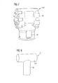
- Fig. 1 shows a vertical cross-sectional perspective view of a T-shaped double-walled fuel supply line element according to an exemplary embodiment of the present disclosure
- Fig. 2 shows a perspective view of the exemplary embodiment of a double-walled fuel supply line element of Fig. 1 ;
- Fig. 3 shows another vertical cross-sectional perspective view of the fuel supply line element of Fig. 1 and 2 ;
- Fig. 4 shows a cross-sectional view of a part of a common rail and a part of a cylinder head of an internal combustion engine with n integrated fuel supply line element according to the present disclosure
- Fig. 5 shows a part of a fuel supply line system including two double-walled fuel supply line elements according to the present disclosure
- Fig. 6 shows a cross-sectional view of the fuel supply line system of Fig. 5 .
- Fig. 7 shows an intermediate core for manufacturing a double-walled fuel supply line element according to the present disclosure
- Fig. 8 shows an inner core for manufacturing a double-walled fuel supply line element according to the present disclosure.
- Fig. 9 shows an illustrating view of a mold for manufacturing a double-walled fuel supply line element, an inner core as shown in Fig. 8 and an intermediate core as shown in Fig 7 being inserted in the mold.
- the double-walled fuel supply line element 5 may comprise an inner line element 10 and an outer line element 40.
- a connecting structure 70 may connect the inner line element 10 and the outer line element 40 such that the inner line element 10 is fixedly arranged within the outer line element 40 and an intermediate hollow space 50 is defined between the inner line element 10 and the outer line element 40.
- the double-walled fuel supply line element 5 may be formed as a simple straight fuel supply line element (not shown), or, e.g. as a T-shaped double-walled fuel supply line element 5 as shown in Figs. 1 to 3 etc. Further, a double-walled fuel supply line element according to the present disclosure also may have an arc form, an X-shape, an L-shape, etc.
- the T-shaped fuel supply line element of Figs. 1 to 3 may be provided with a first inner line hollow space 25 and a second inner line hollow space 26 connected to the first inner line hollow space 25 and forming a T-shaped hollow space 25, 26.
- the first inner line hollow space 25 and the second inner line hollow space 26 are defined by an inner surface 15 of the T-shaped inner line element 10. Accordingly, the first inner line hollow space 25 may be open to two opposite sides, namely end faces 27 and 29.
- the second inner line hollow space 26 may open to another end face 28.
- the outer line element 40 may surround the inner line element 10 enclosing the intermediate hollow space 50.
- An inner surface 45 of the outer line element 40 and the outer surface 20 of the inner line element 10 may define the intermediate hollow space 50.
- connection structure 70 may comprise one or more elements or links extending from an outer side of the inner element 10 to an inner part of the outer line element 40.
- the shape of these links can be seen particularly in Figs. 1 to 3 .
- the links 70 are arranged, e.g., at the neighborhood of end faces 27, 28 and 29. End face 27 and end face 29 are opposite to each other and end face 28 extends in a direction enclosing an angle of e.g. about 90° to a middle axis extending between the two end faces 27 and 29.
- the end face 27 may comprise a connection surface 30 configured to be connected to a similar connection surface of another associated double-walled fuel supply line element 5.
- the other end face 29 of the double-walled fuel supply line element 5 may be configured identical or different to the end face 27. The same may apply to the third end face 28.
- connection flange may comprise one or more mounting holes 80 in which mounting screws 85 may extend (see e.g. Fig. 5 ). Additional connection holes 90 may extend parallel to the hollow space 26. These connection holes 90 may be configured to receive further mounting screws 95.
- the connection flange may be configured to be connected to a part of a cylinder head 102 of an internal combustion engine, see e.g. Figs. 4 and 6 .
- connection holes 90 may not be provided in elongated gates as shown, but be provided in the connection flange.
- All parts shown in Figs. 1 to 3 of the exemplary embodiments of a double-walled fuel supply line element 5 may be integrally casted, for example from a material selected from the group consisting of cast iron, ductile iron as e.g. EN-GJS-400-15.
- the ductile cast iron designated EN-GJS-400-15 may have specific characteristics as described in the European Norm (EN). Particularly this material, also known as ductile cast iron, nodular cast iron, spheroidal graphite iron, and spherulitic graphite cast iron, may provide an adequate gas proofness, strength and stability for the application of a fuel supply line element as described herein.
- Fig. 4 illustrates an exemplary usage of a double-walled fuel supply line element 5 as shown in Figs. 1 to 3 .
- the double-walled fuel supply line element 5 has a T-shape and forms part of a common rail of a double-walled fuel line supply system 100.
- double-walled fuel supply line elements e.g. a common rail end part 103 and an common rail intermediate part 105, are mounted via connection screws 101. These connection screws 101 may extend into the connection holes 90 shown in Figs. 2 and 3 .
- Sealing elements 104 may be arranged intermediate to the end faces 27, 29 of the fuel supply line element 5 and the other double-walled fuel supply line elements 105, 103.
- the third end face 28 of the T-shaped double-walled fuel supply line element 5 may be connected to the cylinder head 102.
- Fig. 5 shows a very similar fuel supply line system as Fig. 4 including two double-walled fuel supply elements 5.
- a drain/monitoring line 200 extends parallel to the fuel supply line system 100.
- Connection parts 205 connect the intermediate hollow space 50 of each double-walled fuel supply line element 5 to the drain-monitoring line 200. This can be particularly seen in the cross-sectional view of Fig. 6 .
- the drain/monitoring line 200 may comprise a shut-off valve 210.
- the shut-off valve 210 may connect or separate two adjacent parts of the drain/monitoring line 200.
- each fuel supply line element 5 provides a connection between the fuel supply line system 100 and gas inlet valves 220.
- the gas inlet valves 220 may be configured to control the amount of gaseous fuel to be guided respectively to a cylinder of an internal combustion engine being operated in a gas operating mode.
- a compensation element 215 may be provided between the two fuel supply line elements 5 for compensating length changes caused by temperature changes.
- the fuel supply line elements 5, the compensation element 215 and all other parts of the fuel supply line system 100 may have a double-walled configuration.
- an intermediate core 150 as shown in Fig. 7 may comprise an intermediate core part 155 and a second intermediate core part 160.
- the intermediate core part 150 may be shaped such that it is identical with the intermediate hollow space 50 between the inner line element 10 and the outer line element 40.
- the inner core 120 may comprise a first inner core part 125 and a second inner core part 130. These inner core parts 125, 130 may define the inner hollow space 15 of the fuel line element 5.
- the outer mould 140 may define the outer surface of the outer line element 40.
- the double-walled fuel supply line element 5 of Figs. 1-3 may be part of a common rail fuel supply line system 100. Accordingly, the fuel supply line element 5 may be mounted to a cylinder head 102 of an internal combustion engine as shown in Fig. 4 and described above in more details.
- a gaseous fuel may be stored and distributed via the fuel supply line element 5 to gas inlet valves 220 shown in Fig. 5 . If there is any leakage in the inner line element 10, the gaseous fuel may enter the intermediate hollow space 50 defined in the double-walled fuel supply line element 5.
- the double-walled fuel supply line element 5 is connected to opposite fuel supply line elements 103, 105 (see Fig.
- the double-walled fuel supply line elements 5 are connected via connection parts 205 to the drain/monitoring line 200 and the leaked fuel may be guided via the line 200 back to a reservoir (not shown).
- the shut-off valve 210 may be used to connect or separate various parts of the line 200 for monitoring purposes or fault detection purposes.
- the inner core 100 is arranged within the intermediate core 150.
- the intermediate core 150 may comprise two separate parts so that the inner core 120 may be placed in the intermediate core and the second part of the intermediate core is then put on the corresponding other intermediate core part.
- the intermediate core 150 housing the inner core 120 may then be set in the mold 140 in such a distance that the desired thickness of the outer line element 40 is defined.
- the mold 140 housing the intermediate core 150 and in the intermediate core 150 the inner core 120 is filled with a cast material, for example, a material as mentioned herein, e.g. cast iron etc.
- the whole mold and/or the cast material is cooled down.
- the inner core 120, the intermediate core 150 and the mould 140 are removed.
- the inner core 120 and the intermediate core 150 will be destroyed such that parts of the inner core 120 and/or the intermediate core 150 may be pulled out of the casted product.
- a one-piece casted double-walled fuel supply line element 5 is manufactured and may be subsequently machined, if necessary.
- a double-walled fuel supply line element particularly an element 5 as described above and illustrated in the Figs. may be used in a fuel supply system configured to be used e.g. for supplying middle and large sized internal combustion engines as used for example in ships, vessels or electric power plants.
- double-walled line element might be particularly configured to be used in fuel supply systems, it might also be possible to use such a double-walled line element in any other systems where liquid or gaseous mediums shall be guided from one place to another place within an inner line element protected by an outer line element.
- the intermediate hollow space defined by the outer line element surrounding the inner line element may be configured and used to receive leaking fuel and/or drain and/or monitor possible a leakage of fuel, e.g. gas, out of the inner line element.
- Another usage may comprise cooling or heating a medium flowing in the inner line element by means of a media flowing in the intermediate hollow space defined by the outer line element.
- a double-walled line element according to the present disclosure may be designed as a straight line element, a T-shaped line element, a corner like line element, a cross like line element, or as a band like element.
- a double-walled line element according to the present disclosure may also be provided with at least one additional outer line element such that a multi-walled supply line element may be provided.
- line used herein may be replaced by the term "pipe”. Accordingly, the two terms may both be used for naming a medium guiding/distributing element according to the present disclosure.
Landscapes
- Engineering & Computer Science (AREA)
- General Engineering & Computer Science (AREA)
- Chemical & Material Sciences (AREA)
- Mechanical Engineering (AREA)
- Combustion & Propulsion (AREA)
- Oil, Petroleum & Natural Gas (AREA)
- General Chemical & Material Sciences (AREA)
- Chemical Kinetics & Catalysis (AREA)
- Life Sciences & Earth Sciences (AREA)
- Sustainable Development (AREA)
- Sustainable Energy (AREA)
- Transportation (AREA)
- Fuel-Injection Apparatus (AREA)
Abstract
Description
- The present disclosure generally refers to a double-walled fuel supply line element configured to be used in a fuel supply system of an internal combustion engine. Particularly, the present disclosure refers to a double-walled fuel supply line element configured to be used in a fuel supply system which is configured and designed to supply gaseous fuels and/or fluid fuels.
- Furthermore, the present disclosure refers to a method for manufacturing a double-walled fuel supply line element of the type mentioned above.
- Fuel supply systems which are particularly used in gas or dual-fuel engines may have to be specifically designed due to security purposes. For example, double-wall or multi-wall configurations have to be applied to all gas leading components as for example lines/pipes or connection elements to be used in gas or dual-fuel engines. Such double-walled fuel pipe elements or fuel supply line elements may be used on ships or vessels where gas or dual-fuel engines may be operated. The same applies to gas or dual-fuel engines used to generate electrical power.
- Double-walled configurations of fuel supply line elements may be used to prevent leakage of gas into the atmosphere in case of damage of an inner pipe of such fuel supply pipes and fuel supply line elements, respectively. Double-walled fuel supply pipes may be configured such that fuel may be piped from a first place to a second place located in a distance to the first place within an inner pipe surrounded by an outer pipe.
- Additionally, a fuel supply line element may be configured such that fuel may be guided from a first place to a second place and to at least a third place C differing from the first and second places A and B. All necessary inner pipe parts of such a line element may be surrounded by outer pipe parts commonly forming an outer shell.
- For a fuel distribution from a common supply line to individual fuel inlets, e.g. particularly including gas inlet valves arranged at cylinder heads, a T-shaped connection element may be necessary. Up to now, T-shaped connection elements have been provided as welded assemblies comprising a plurality of components. Accordingly, a high degree of production precision may be necessary. The variety of welded seams may cause a high fault potential. The effort for monitoring and checking during manufacturing and operation of such supply lines may be high.
-
JP 63018124 A -
WO 99/37945 A1 WO 99/37945 A1 JP 63018124 A1 - The present disclosure is directed, at least in part, to improving or overcoming one or more aspects of the prior systems.
- In one aspect the present disclosure refers to a double-walled fuel supply line element configured to be used in a fuel supply system. The double-walled fuel supply line element may be provided with a first end face and a second end face. The double-walled fuel supply line element may comprise an inner line element, an outer line element, and a connecting structure configured to fixedly arrange the outer line element around the inner line element such that a hollow space being open at the two end faces of the double-walled fuel supply line element is provided between the inner line element and the outer line element. The inner line element, the outer line element, and the connecting structure may be integrally casted. The term "integrally casted" may mean casted in one piece.
- In another aspect the present disclosure refers to a method for manufacturing a double-walled fuel supply line element. The method may comprise the step of providing an inner core defining an inner surface of an inner line element. Further, the method may comprise the step of providing an intermediate core defining an outer surface of the inner line element and an inner surface of an outer line element. The method may further comprise the steps of providing a mold defining the outer surface of the outer line element, arranging the inner core and the intermediate core in the mold, and filling all gaps defined by the inner core, the intermediate core and the mold with a cast material. Finally, the method may comprise the steps of cooling down the cast material and removing the inner core, the intermediate core, and the mold. The intermediate core or the mold or the intermediate core and the mold may be configured such that a connecting structure is provided between the inner line element and the outer line element, the connecting structure may be configured to fixedly arrange the outer line element around the inner line element such that a hollow space opens out at at least one of a first end face and a second end face of the fuel supply line element.
- Other features and aspects of this disclosure will be apparent from the following description and the accompanying drawings.
-
Fig. 1 shows a vertical cross-sectional perspective view of a T-shaped double-walled fuel supply line element according to an exemplary embodiment of the present disclosure; -
Fig. 2 shows a perspective view of the exemplary embodiment of a double-walled fuel supply line element ofFig. 1 ; -
Fig. 3 shows another vertical cross-sectional perspective view of the fuel supply line element ofFig. 1 and 2 ; -
Fig. 4 shows a cross-sectional view of a part of a common rail and a part of a cylinder head of an internal combustion engine with n integrated fuel supply line element according to the present disclosure; -
Fig. 5 shows a part of a fuel supply line system including two double-walled fuel supply line elements according to the present disclosure; -
Fig. 6 shows a cross-sectional view of the fuel supply line system ofFig. 5 . -
Fig. 7 shows an intermediate core for manufacturing a double-walled fuel supply line element according to the present disclosure; -
Fig. 8 shows an inner core for manufacturing a double-walled fuel supply line element according to the present disclosure; and -
Fig. 9 shows an illustrating view of a mold for manufacturing a double-walled fuel supply line element, an inner core as shown inFig. 8 and an intermediate core as shown inFig 7 being inserted in the mold. - Referring to
Figs. 1 to 3 , a first exemplary embodiment of a double-walled fuelsupply line element 5 according to the present disclosure. The double-walled fuelsupply line element 5 may comprise aninner line element 10 and anouter line element 40. Aconnecting structure 70 may connect theinner line element 10 and theouter line element 40 such that theinner line element 10 is fixedly arranged within theouter line element 40 and an intermediatehollow space 50 is defined between theinner line element 10 and theouter line element 40. - The double-walled fuel
supply line element 5 may be formed as a simple straight fuel supply line element (not shown), or, e.g. as a T-shaped double-walled fuelsupply line element 5 as shown inFigs. 1 to 3 etc. Further, a double-walled fuel supply line element according to the present disclosure also may have an arc form, an X-shape, an L-shape, etc. - The T-shaped fuel supply line element of
Figs. 1 to 3 may be provided with a first inner linehollow space 25 and a second inner linehollow space 26 connected to the first inner linehollow space 25 and forming a T-shapedhollow space hollow space 25 and the second inner linehollow space 26 are defined by aninner surface 15 of the T-shapedinner line element 10. Accordingly, the first inner linehollow space 25 may be open to two opposite sides, namelyend faces hollow space 26 may open to anotherend face 28. - The
outer line element 40 may surround theinner line element 10 enclosing the intermediatehollow space 50. Aninner surface 45 of theouter line element 40 and theouter surface 20 of theinner line element 10 may define the intermediatehollow space 50. - The
connection structure 70 may comprise one or more elements or links extending from an outer side of theinner element 10 to an inner part of theouter line element 40. The shape of these links can be seen particularly inFigs. 1 to 3 . In these exemplary embodiments ofFigs. 1 to 3 thelinks 70 are arranged, e.g., at the neighborhood of end faces 27, 28 and 29.End face 27 andend face 29 are opposite to each other andend face 28 extends in a direction enclosing an angle of e.g. about 90° to a middle axis extending between the twoend faces - As illustrated in
Fig. 2 theend face 27 may comprise aconnection surface 30 configured to be connected to a similar connection surface of another associated double-walled fuelsupply line element 5. Theother end face 29 of the double-walled fuelsupply line element 5 may be configured identical or different to theend face 27. The same may apply to thethird end face 28. - However, in the present exemplary embodiments shown in
Figs. 1 to 3 , theend face 28 might be configured different, particularly including a connection flange. The connection flange may comprise one or more mountingholes 80 in which mounting screws 85 may extend (see e.g.Fig. 5 ). Additional connection holes 90 may extend parallel to thehollow space 26. These connection holes 90 may be configured to receive further mounting screws 95. For example, the connection flange may be configured to be connected to a part of acylinder head 102 of an internal combustion engine, see e.g.Figs. 4 and6 . - In another exemplary embodiment of the fuel
supply line element 5 illustrated in e.g.Fig. 2 , the connection holes 90 may not be provided in elongated gates as shown, but be provided in the connection flange. - All parts shown in
Figs. 1 to 3 of the exemplary embodiments of a double-walled fuelsupply line element 5 may be integrally casted, for example from a material selected from the group consisting of cast iron, ductile iron as e.g. EN-GJS-400-15. The ductile cast iron designated EN-GJS-400-15 may have specific characteristics as described in the European Norm (EN). Particularly this material, also known as ductile cast iron, nodular cast iron, spheroidal graphite iron, and spherulitic graphite cast iron, may provide an adequate gas proofness, strength and stability for the application of a fuel supply line element as described herein. -
Fig. 4 illustrates an exemplary usage of a double-walled fuelsupply line element 5 as shown inFigs. 1 to 3 . Here, the double-walled fuelsupply line element 5 has a T-shape and forms part of a common rail of a double-walled fuelline supply system 100. On both end faces 27 and 29 of the fuelsupply line element 5 double-walled fuel supply line elements, e.g. a commonrail end part 103 and an common railintermediate part 105, are mounted via connection screws 101. These connection screws 101 may extend into the connection holes 90 shown inFigs. 2 and3 . Sealingelements 104 may be arranged intermediate to the end faces 27, 29 of the fuelsupply line element 5 and the other double-walled fuelsupply line elements third end face 28 of the T-shaped double-walled fuelsupply line element 5 may be connected to thecylinder head 102. -
Fig. 5 shows a very similar fuel supply line system asFig. 4 including two double-walledfuel supply elements 5. Here, a drain/monitoring line 200 extends parallel to the fuelsupply line system 100.Connection parts 205 connect the intermediatehollow space 50 of each double-walled fuelsupply line element 5 to the drain-monitoring line 200. This can be particularly seen in the cross-sectional view ofFig. 6 . The drain/monitoring line 200 may comprise a shut-offvalve 210. The shut-offvalve 210 may connect or separate two adjacent parts of the drain/monitoring line 200. Here, each fuelsupply line element 5 provides a connection between the fuelsupply line system 100 andgas inlet valves 220. Thegas inlet valves 220 may be configured to control the amount of gaseous fuel to be guided respectively to a cylinder of an internal combustion engine being operated in a gas operating mode. Acompensation element 215 may be provided between the two fuelsupply line elements 5 for compensating length changes caused by temperature changes. The fuelsupply line elements 5, thecompensation element 215 and all other parts of the fuelsupply line system 100 may have a double-walled configuration. - For manufacturing such an integrally casted double-walled fuel
supply line element 5 anintermediate core 150 as shown inFig. 7 , an inner core as shown inFig. 8 , and amould 140 as schematically illustrated in claim 9 may be used. The intermediate core ofFig. 7 may comprise anintermediate core part 155 and a secondintermediate core part 160. Theintermediate core part 150 may be shaped such that it is identical with the intermediatehollow space 50 between theinner line element 10 and theouter line element 40. Theinner core 120 may comprise a firstinner core part 125 and a secondinner core part 130. Theseinner core parts hollow space 15 of thefuel line element 5. Theouter mould 140 may define the outer surface of theouter line element 40. - Referring to
Figs. 1-3 and particularlyFigs. 4 to 6 , various usages of a double-walled fuelsupply line element 5 according to the present disclosure are described in the following. - The double-walled fuel
supply line element 5 ofFigs. 1-3 may be part of a common rail fuelsupply line system 100. Accordingly, the fuelsupply line element 5 may be mounted to acylinder head 102 of an internal combustion engine as shown inFig. 4 and described above in more details. In the fuel supply line system 100 a gaseous fuel may be stored and distributed via the fuelsupply line element 5 togas inlet valves 220 shown inFig. 5 . If there is any leakage in theinner line element 10, the gaseous fuel may enter the intermediatehollow space 50 defined in the double-walled fuelsupply line element 5. The double-walled fuelsupply line element 5 is connected to opposite fuelsupply line elements 103, 105 (seeFig. 4 ) and these further fuelsupply line elements supply line element 5 such that the intermediatehollow space 50 is fluidly connected to the hollow space of the double-walled fuelsupply line elements hollow space 25 of the double-walled fuelsupply line element 5 cannot enter into the atmosphere, but is received in the intermediatehollow space 50. Accordingly, security is guaranteed. - In some cases, as for example shown in
Fig. 5 , the double-walled fuelsupply line elements 5 are connected viaconnection parts 205 to the drain/monitoring line 200 and the leaked fuel may be guided via theline 200 back to a reservoir (not shown). If necessary, the shut-offvalve 210 may be used to connect or separate various parts of theline 200 for monitoring purposes or fault detection purposes. - Referring to
Figs. 7 to 9 an exemplary method for manufacturing a double-walled fuelsupply line element 5 is described in the following. Theinner core 100 is arranged within theintermediate core 150. For this purpose, theintermediate core 150 may comprise two separate parts so that theinner core 120 may be placed in the intermediate core and the second part of the intermediate core is then put on the corresponding other intermediate core part. Theintermediate core 150 housing theinner core 120 may then be set in themold 140 in such a distance that the desired thickness of theouter line element 40 is defined. - Subsequently, the
mold 140 housing theintermediate core 150 and in theintermediate core 150 theinner core 120 is filled with a cast material, for example, a material as mentioned herein, e.g. cast iron etc. - Afterwards, the whole mold and/or the cast material is cooled down. Finally, the
inner core 120, theintermediate core 150 and themould 140 are removed. For example, theinner core 120 and theintermediate core 150 will be destroyed such that parts of theinner core 120 and/or theintermediate core 150 may be pulled out of the casted product. - Accordingly, a one-piece casted double-walled fuel
supply line element 5 is manufactured and may be subsequently machined, if necessary. - A double-walled fuel supply line element, particularly an
element 5 as described above and illustrated in the Figs. may be used in a fuel supply system configured to be used e.g. for supplying middle and large sized internal combustion engines as used for example in ships, vessels or electric power plants. - Although such a double-walled line element might be particularly configured to be used in fuel supply systems, it might also be possible to use such a double-walled line element in any other systems where liquid or gaseous mediums shall be guided from one place to another place within an inner line element protected by an outer line element. The intermediate hollow space defined by the outer line element surrounding the inner line element may be configured and used to receive leaking fuel and/or drain and/or monitor possible a leakage of fuel, e.g. gas, out of the inner line element.
- Another usage may comprise cooling or heating a medium flowing in the inner line element by means of a media flowing in the intermediate hollow space defined by the outer line element.
- A double-walled line element according to the present disclosure may be designed as a straight line element, a T-shaped line element, a corner like line element, a cross like line element, or as a band like element. In addition, a double-walled line element according to the present disclosure may also be provided with at least one additional outer line element such that a multi-walled supply line element may be provided.
- The term "line" used herein may be replaced by the term "pipe". Accordingly, the two terms may both be used for naming a medium guiding/distributing element according to the present disclosure.
- Although the preferred embodiments of this invention have been described herein, improvements and modifications may be incorporated without departing from the scope of the following claims.
Claims (9)
- A double-walled fuel supply line element (5) configured to be used in a fuel supply system (100) an internal combustion engine, comprising:an inner line element (10);an outer line element (40); anda connecting structure (70) configured to fixedly arrange the outer line element (40) around the inner line element (10) such that a tubular hollow space (50) is provided between the inner line element (10) and the outer line element (40);the inner line element (10), the outer line element (40), and the connecting structure (70) being integrally casted.
- The double-walled fuel supply line element (5) of claim 1, further comprising:a first end face (27) configured to be connected to an adjacent double-walled fuel supply line element (105);at least one second end face (28, 29) arranged in a distance to the first connection face (30) and configured to be connected to another adjacent double-walled fuel supply line element.
- The double-walled fuel supply line element of claim 1 or 2, the inner line element (10) and the outer line element (40) each being provided with at least two line openings.
- The double-walled fuel supply line element of claim 2 or 3, the shape of the double walled fuel supply line element being selected from the group consisting of: a straight shape, a T-shape, a L-shape, a corner like shape, a X-shape shape.
- The double-walled fuel supply line element of any one of the preceding claims, the connecting structure (70) being shaped such that at least one opening connected to the intermediate hollow space (25, 26) is provided at at least one end face (27, 28, 29) of the fuel supply line element (5).
- The double-walled fuel supply line element of any one of the preceding claims, the connecting structure (70) including a plurality of fixed links extending between the inner line element (10) and the outer line element (40), the flow cross-section defined by the inner line element (10) and the outer line element (40) being reduced due to the fixed links (70) less than 50%, particularly less than 25%, more particularly, less than 10%.
- The double-walled fuel supply line element of any one of the preceding claims, all parts of the fuel supply pipe element (5) being integrally casted from at least one of the materials of the group comprising non-alloyed cast steel, alloyed cast steel, cast iron, grey cast iron, ductile cast iron as e.g. EN-GJS-400-15, and a cast iron including any additive.
- A method for manufacturing a double-walled fuel supply line element (5), the method comprising:providing an inner core (120) defining an inner surface (15) of an inner line element (10);providing an intermediate core (150) defining an outer surface (20) of the inner line element (10) and an inner surface (45) of an outer line element (40) surrounding the inner line element (10);providing a mold (140) defining the outer surface (46) of the outer line element (40), wherein the intermediate core (150) and/or the mold (140) are configured such that a connecting structure (70) is defined between the inner line element (10) and the outer line element (40), the connecting structure (70) being configured to fixedly arrange the outer line element (40) around the inner line element (10) such that a hollow space (50) opens out at at least one of a first end face (27) and a second end face (28, 29) of the double-walled fuel line element (5);arranging the inner core (120) and the intermediate core (150) in the mold (140);filling the mold (140) with a cast material;cooling down the cast material; andremoving the inner core (120), the intermediate core (150) and the mold (140).
- The method for of claim 8, wherein the cast material is selected from at least one of the materials of the group comprising cast iron, grey cast iron, ductile cast iron as e.g. EN-GJS-400-15, and a cast iron including any additive.
Priority Applications (4)
| Application Number | Priority Date | Filing Date | Title |
|---|---|---|---|
| ES11168267.0T ES2461181T3 (en) | 2011-05-31 | 2011-05-31 | Double wall fuel feed line element |
| EP11168267.0A EP2530294B1 (en) | 2011-05-31 | 2011-05-31 | Double-walled fuel supply line element |
| PCT/EP2012/001930 WO2012163462A1 (en) | 2011-05-31 | 2012-05-04 | Double-walled fuel supply line element |
| KR1020137034457A KR101990652B1 (en) | 2011-05-31 | 2012-05-04 | Double-walled fuel supply line element |
Applications Claiming Priority (1)
| Application Number | Priority Date | Filing Date | Title |
|---|---|---|---|
| EP11168267.0A EP2530294B1 (en) | 2011-05-31 | 2011-05-31 | Double-walled fuel supply line element |
Publications (2)
| Publication Number | Publication Date |
|---|---|
| EP2530294A1 true EP2530294A1 (en) | 2012-12-05 |
| EP2530294B1 EP2530294B1 (en) | 2014-04-09 |
Family
ID=46044638
Family Applications (1)
| Application Number | Title | Priority Date | Filing Date |
|---|---|---|---|
| EP11168267.0A Active EP2530294B1 (en) | 2011-05-31 | 2011-05-31 | Double-walled fuel supply line element |
Country Status (4)
| Country | Link |
|---|---|
| EP (1) | EP2530294B1 (en) |
| KR (1) | KR101990652B1 (en) |
| ES (1) | ES2461181T3 (en) |
| WO (1) | WO2012163462A1 (en) |
Cited By (4)
| Publication number | Priority date | Publication date | Assignee | Title |
|---|---|---|---|---|
| US9234614B2 (en) | 2014-05-05 | 2016-01-12 | Electro-Motive Diesel, Inc. | Assembly for coupling a pair of double-walled tubes |
| WO2017121921A1 (en) * | 2016-01-12 | 2017-07-20 | Wärtsilä Finland Oy | A fuel gas manifold assembly configured to be used in an internal combustion piston engine and an internal combustion piston engine |
| CN106996349A (en) * | 2017-04-19 | 2017-08-01 | 四川森洁燃气设备有限公司 | A kind of combustion gas adjustable type spout structure |
| WO2024134293A1 (en) * | 2022-12-20 | 2024-06-27 | Anglo Belgian Corporation | Apparatus with hydrogen collector unit |
Families Citing this family (6)
| Publication number | Priority date | Publication date | Assignee | Title |
|---|---|---|---|---|
| ES2795351T3 (en) * | 2013-07-17 | 2020-11-23 | Victaulic Co Of America | Couplings that have arcuate rigid ribs |
| EP3256713B1 (en) | 2015-02-09 | 2019-04-03 | Wärtsilä Finland Oy | A fuel supply element configured to be used in a fuel supply pipe system of an internal combustion piston engine and a fuel supply pipe system |
| KR102086885B1 (en) * | 2016-12-29 | 2020-03-09 | 현대중공업 주식회사 | Pipe Structure for Easily Detection Fuel Gas Leak of Dual Fuel Engine |
| KR102157443B1 (en) * | 2019-09-24 | 2020-09-17 | 현대중공업 주식회사 | Gas feeding pipe of double wall structure |
| CN114562391A (en) * | 2020-11-27 | 2022-05-31 | 中国船舶重工集团公司第七一一研究所 | Distributed gas valve group of gas engine |
| EP4249380B1 (en) | 2022-03-21 | 2025-07-30 | Zero Emissions Aerospace Limited | Fuel line safety protection system |
Citations (7)
| Publication number | Priority date | Publication date | Assignee | Title |
|---|---|---|---|---|
| JPS6318124A (en) | 1986-07-11 | 1988-01-26 | Isuzu Motors Ltd | Exhaust pipe structure |
| EP0625637A1 (en) * | 1993-05-17 | 1994-11-23 | MAGNETI MARELLI S.p.A. | Manifold for an internal combustion engine fuel supply device |
| WO1999037945A1 (en) | 1998-01-22 | 1999-07-29 | Grand Prix Silencers B.V. | Multiple pipe comprising an envelope |
| EP1150006A2 (en) * | 2000-04-27 | 2001-10-31 | Wärtsilä Technology Oy AB | Arrangement for locating fuel leakage in connection with a combustion engine |
| US20020046735A1 (en) * | 2000-10-25 | 2002-04-25 | Siemens Automotive, Inc. | Double walled fuel rail |
| EP1469188A1 (en) * | 2003-04-08 | 2004-10-20 | General Motors Corporation | Diesel injection system with dual flow fuel line |
| US20060236979A1 (en) * | 2005-03-24 | 2006-10-26 | Ems-Chemie Ag | Line system for fluids having volatile components |
-
2011
- 2011-05-31 ES ES11168267.0T patent/ES2461181T3/en active Active
- 2011-05-31 EP EP11168267.0A patent/EP2530294B1/en active Active
-
2012
- 2012-05-04 WO PCT/EP2012/001930 patent/WO2012163462A1/en not_active Ceased
- 2012-05-04 KR KR1020137034457A patent/KR101990652B1/en active Active
Patent Citations (7)
| Publication number | Priority date | Publication date | Assignee | Title |
|---|---|---|---|---|
| JPS6318124A (en) | 1986-07-11 | 1988-01-26 | Isuzu Motors Ltd | Exhaust pipe structure |
| EP0625637A1 (en) * | 1993-05-17 | 1994-11-23 | MAGNETI MARELLI S.p.A. | Manifold for an internal combustion engine fuel supply device |
| WO1999037945A1 (en) | 1998-01-22 | 1999-07-29 | Grand Prix Silencers B.V. | Multiple pipe comprising an envelope |
| EP1150006A2 (en) * | 2000-04-27 | 2001-10-31 | Wärtsilä Technology Oy AB | Arrangement for locating fuel leakage in connection with a combustion engine |
| US20020046735A1 (en) * | 2000-10-25 | 2002-04-25 | Siemens Automotive, Inc. | Double walled fuel rail |
| EP1469188A1 (en) * | 2003-04-08 | 2004-10-20 | General Motors Corporation | Diesel injection system with dual flow fuel line |
| US20060236979A1 (en) * | 2005-03-24 | 2006-10-26 | Ems-Chemie Ag | Line system for fluids having volatile components |
Cited By (5)
| Publication number | Priority date | Publication date | Assignee | Title |
|---|---|---|---|---|
| US9234614B2 (en) | 2014-05-05 | 2016-01-12 | Electro-Motive Diesel, Inc. | Assembly for coupling a pair of double-walled tubes |
| WO2017121921A1 (en) * | 2016-01-12 | 2017-07-20 | Wärtsilä Finland Oy | A fuel gas manifold assembly configured to be used in an internal combustion piston engine and an internal combustion piston engine |
| CN106996349A (en) * | 2017-04-19 | 2017-08-01 | 四川森洁燃气设备有限公司 | A kind of combustion gas adjustable type spout structure |
| WO2024134293A1 (en) * | 2022-12-20 | 2024-06-27 | Anglo Belgian Corporation | Apparatus with hydrogen collector unit |
| BE1031157B1 (en) * | 2022-12-20 | 2024-07-15 | Anglo Belgian Corp | HYDROGEN APPLICATION WITH COLLECTOR UNIT |
Also Published As
| Publication number | Publication date |
|---|---|
| WO2012163462A1 (en) | 2012-12-06 |
| ES2461181T3 (en) | 2014-05-19 |
| EP2530294B1 (en) | 2014-04-09 |
| KR101990652B1 (en) | 2019-09-30 |
| KR20140045959A (en) | 2014-04-17 |
Similar Documents
| Publication | Publication Date | Title |
|---|---|---|
| EP2530294B1 (en) | Double-walled fuel supply line element | |
| US20150285421A1 (en) | Double-walled fuel supply line element and connecting flange for the same | |
| US10221999B2 (en) | Pressure vessel fluid manifold assembly | |
| CA2580327C (en) | Fuel conveying member with side-brazed sealing members | |
| US9222365B2 (en) | Bearing arrangement for a shaft of a turbocharger | |
| WO2012070946A1 (en) | Gas supply system for a gas engine | |
| JP5468673B1 (en) | Gasket and cylinder head gasket | |
| US12168966B2 (en) | Modular and scalable rail fuel system architecture | |
| US10774954B2 (en) | Fluid supply conduit and method for providing such a conduit | |
| ITBS20120097A1 (en) | VALVE WITH ALUMINUM BODY AND ANTI-CORROSION SYSTEM | |
| JP5800792B2 (en) | Connecting flange for high pressure conduit | |
| US10082100B2 (en) | Cylinder head and engine block configuration | |
| CN105190130B (en) | The cylinder head gasket that mixing boxing connects | |
| KR100739500B1 (en) | Cylinder head gasket | |
| EP2362120B1 (en) | Seal structure for engine | |
| KR20140111321A (en) | Cooling arrangement for valve seat | |
| KR101795352B1 (en) | End cover for charge air cooler | |
| EP1528300A1 (en) | Cylinder heat gasket | |
| KR20160097043A (en) | Cover for insulating a exhaust pipe | |
| FI114111B (en) | Method and apparatus for reducing corrosion | |
| WO2009063573A1 (en) | Stave cooler for blast furnace | |
| EP1854994B1 (en) | Protective device for terminations of pipes carrying fluids under pressure in an engine, especially for marine or special applications | |
| GB2601191A (en) | A rocker housing for an internal combustion engine | |
| KR20130044307A (en) | Cylinder head and internal combustion engine equipped therewith |
Legal Events
| Date | Code | Title | Description |
|---|---|---|---|
| PUAI | Public reference made under article 153(3) epc to a published international application that has entered the european phase |
Free format text: ORIGINAL CODE: 0009012 |
|
| AK | Designated contracting states |
Kind code of ref document: A1 Designated state(s): AL AT BE BG CH CY CZ DE DK EE ES FI FR GB GR HR HU IE IS IT LI LT LU LV MC MK MT NL NO PL PT RO RS SE SI SK SM TR |
|
| AX | Request for extension of the european patent |
Extension state: BA ME |
|
| RIN1 | Information on inventor provided before grant (corrected) |
Inventor name: REBELEIN, WERNER Inventor name: USLU, FUAT Inventor name: BAKINDI, BILAL Inventor name: JANZEN, JAN Inventor name: BLEYER, BENJAMIN |
|
| 17P | Request for examination filed |
Effective date: 20130605 |
|
| RBV | Designated contracting states (corrected) |
Designated state(s): AL AT BE BG CH CY CZ DE DK EE ES FI FR GB GR HR HU IE IS IT LI LT LU LV MC MK MT NL NO PL PT RO RS SE SI SK SM TR |
|
| RIC1 | Information provided on ipc code assigned before grant |
Ipc: F16L 39/00 20060101ALI20130821BHEP Ipc: F02M 55/02 20060101ALI20130821BHEP Ipc: F02M 55/00 20060101AFI20130821BHEP Ipc: F02M 63/00 20060101ALN20130821BHEP Ipc: B60K 15/01 20060101ALI20130821BHEP Ipc: F16L 41/02 20060101ALI20130821BHEP Ipc: F16L 9/19 20060101ALI20130821BHEP Ipc: F02D 19/06 20060101ALI20130821BHEP Ipc: F02M 69/46 20060101ALI20130821BHEP Ipc: F02M 43/00 20060101ALI20130821BHEP Ipc: F02M 37/00 20060101ALI20130821BHEP Ipc: F02M 21/02 20060101ALI20130821BHEP |
|
| RIC1 | Information provided on ipc code assigned before grant |
Ipc: F02M 63/00 20060101ALN20130823BHEP Ipc: F16L 39/00 20060101ALI20130823BHEP Ipc: F16L 41/02 20060101ALI20130823BHEP Ipc: F02M 55/00 20060101AFI20130823BHEP Ipc: F02M 21/02 20060101ALI20130823BHEP Ipc: F02D 19/06 20060101ALI20130823BHEP Ipc: F02M 69/46 20060101ALI20130823BHEP Ipc: F02M 43/00 20060101ALI20130823BHEP Ipc: B60K 15/01 20060101ALI20130823BHEP Ipc: F16L 9/19 20060101ALI20130823BHEP Ipc: F02M 37/00 20060101ALI20130823BHEP Ipc: F02M 55/02 20060101ALI20130823BHEP |
|
| GRAP | Despatch of communication of intention to grant a patent |
Free format text: ORIGINAL CODE: EPIDOSNIGR1 |
|
| INTG | Intention to grant announced |
Effective date: 20131024 |
|
| GRAS | Grant fee paid |
Free format text: ORIGINAL CODE: EPIDOSNIGR3 |
|
| GRAA | (expected) grant |
Free format text: ORIGINAL CODE: 0009210 |
|
| AK | Designated contracting states |
Kind code of ref document: B1 Designated state(s): AL AT BE BG CH CY CZ DE DK EE ES FI FR GB GR HR HU IE IS IT LI LT LU LV MC MK MT NL NO PL PT RO RS SE SI SK SM TR |
|
| REG | Reference to a national code |
Ref country code: GB Ref legal event code: FG4D |
|
| REG | Reference to a national code |
Ref country code: CH Ref legal event code: EP Ref country code: AT Ref legal event code: REF Ref document number: 661486 Country of ref document: AT Kind code of ref document: T Effective date: 20140415 |
|
| REG | Reference to a national code |
Ref country code: ES Ref legal event code: FG2A Ref document number: 2461181 Country of ref document: ES Kind code of ref document: T3 Effective date: 20140519 |
|
| REG | Reference to a national code |
Ref country code: IE Ref legal event code: FG4D |
|
| REG | Reference to a national code |
Ref country code: DE Ref legal event code: R096 Ref document number: 602011006000 Country of ref document: DE Effective date: 20140522 |
|
| REG | Reference to a national code |
Ref country code: AT Ref legal event code: MK05 Ref document number: 661486 Country of ref document: AT Kind code of ref document: T Effective date: 20140409 |
|
| REG | Reference to a national code |
Ref country code: NO Ref legal event code: T2 Effective date: 20140409 |
|
| REG | Reference to a national code |
Ref country code: NL Ref legal event code: VDEP Effective date: 20140409 |
|
| REG | Reference to a national code |
Ref country code: LT Ref legal event code: MG4D |
|
| PG25 | Lapsed in a contracting state [announced via postgrant information from national office to epo] |
Ref country code: IS Free format text: LAPSE BECAUSE OF FAILURE TO SUBMIT A TRANSLATION OF THE DESCRIPTION OR TO PAY THE FEE WITHIN THE PRESCRIBED TIME-LIMIT Effective date: 20140809 Ref country code: NL Free format text: LAPSE BECAUSE OF FAILURE TO SUBMIT A TRANSLATION OF THE DESCRIPTION OR TO PAY THE FEE WITHIN THE PRESCRIBED TIME-LIMIT Effective date: 20140409 Ref country code: BG Free format text: LAPSE BECAUSE OF FAILURE TO SUBMIT A TRANSLATION OF THE DESCRIPTION OR TO PAY THE FEE WITHIN THE PRESCRIBED TIME-LIMIT Effective date: 20140709 Ref country code: LT Free format text: LAPSE BECAUSE OF FAILURE TO SUBMIT A TRANSLATION OF THE DESCRIPTION OR TO PAY THE FEE WITHIN THE PRESCRIBED TIME-LIMIT Effective date: 20140409 Ref country code: GR Free format text: LAPSE BECAUSE OF FAILURE TO SUBMIT A TRANSLATION OF THE DESCRIPTION OR TO PAY THE FEE WITHIN THE PRESCRIBED TIME-LIMIT Effective date: 20140710 |
|
| PG25 | Lapsed in a contracting state [announced via postgrant information from national office to epo] |
Ref country code: PL Free format text: LAPSE BECAUSE OF FAILURE TO SUBMIT A TRANSLATION OF THE DESCRIPTION OR TO PAY THE FEE WITHIN THE PRESCRIBED TIME-LIMIT Effective date: 20140409 Ref country code: LV Free format text: LAPSE BECAUSE OF FAILURE TO SUBMIT A TRANSLATION OF THE DESCRIPTION OR TO PAY THE FEE WITHIN THE PRESCRIBED TIME-LIMIT Effective date: 20140409 Ref country code: RS Free format text: LAPSE BECAUSE OF FAILURE TO SUBMIT A TRANSLATION OF THE DESCRIPTION OR TO PAY THE FEE WITHIN THE PRESCRIBED TIME-LIMIT Effective date: 20140409 Ref country code: HR Free format text: LAPSE BECAUSE OF FAILURE TO SUBMIT A TRANSLATION OF THE DESCRIPTION OR TO PAY THE FEE WITHIN THE PRESCRIBED TIME-LIMIT Effective date: 20140409 Ref country code: SE Free format text: LAPSE BECAUSE OF FAILURE TO SUBMIT A TRANSLATION OF THE DESCRIPTION OR TO PAY THE FEE WITHIN THE PRESCRIBED TIME-LIMIT Effective date: 20140409 Ref country code: AT Free format text: LAPSE BECAUSE OF FAILURE TO SUBMIT A TRANSLATION OF THE DESCRIPTION OR TO PAY THE FEE WITHIN THE PRESCRIBED TIME-LIMIT Effective date: 20140409 |
|
| PG25 | Lapsed in a contracting state [announced via postgrant information from national office to epo] |
Ref country code: PT Free format text: LAPSE BECAUSE OF FAILURE TO SUBMIT A TRANSLATION OF THE DESCRIPTION OR TO PAY THE FEE WITHIN THE PRESCRIBED TIME-LIMIT Effective date: 20140811 |
|
| REG | Reference to a national code |
Ref country code: CH Ref legal event code: PL |
|
| REG | Reference to a national code |
Ref country code: DE Ref legal event code: R097 Ref document number: 602011006000 Country of ref document: DE |
|
| PG25 | Lapsed in a contracting state [announced via postgrant information from national office to epo] |
Ref country code: RO Free format text: LAPSE BECAUSE OF FAILURE TO SUBMIT A TRANSLATION OF THE DESCRIPTION OR TO PAY THE FEE WITHIN THE PRESCRIBED TIME-LIMIT Effective date: 20140409 Ref country code: CH Free format text: LAPSE BECAUSE OF NON-PAYMENT OF DUE FEES Effective date: 20140531 Ref country code: LI Free format text: LAPSE BECAUSE OF NON-PAYMENT OF DUE FEES Effective date: 20140531 Ref country code: MC Free format text: LAPSE BECAUSE OF FAILURE TO SUBMIT A TRANSLATION OF THE DESCRIPTION OR TO PAY THE FEE WITHIN THE PRESCRIBED TIME-LIMIT Effective date: 20140409 Ref country code: SK Free format text: LAPSE BECAUSE OF FAILURE TO SUBMIT A TRANSLATION OF THE DESCRIPTION OR TO PAY THE FEE WITHIN THE PRESCRIBED TIME-LIMIT Effective date: 20140409 Ref country code: EE Free format text: LAPSE BECAUSE OF FAILURE TO SUBMIT A TRANSLATION OF THE DESCRIPTION OR TO PAY THE FEE WITHIN THE PRESCRIBED TIME-LIMIT Effective date: 20140409 Ref country code: CZ Free format text: LAPSE BECAUSE OF FAILURE TO SUBMIT A TRANSLATION OF THE DESCRIPTION OR TO PAY THE FEE WITHIN THE PRESCRIBED TIME-LIMIT Effective date: 20140409 Ref country code: DK Free format text: LAPSE BECAUSE OF FAILURE TO SUBMIT A TRANSLATION OF THE DESCRIPTION OR TO PAY THE FEE WITHIN THE PRESCRIBED TIME-LIMIT Effective date: 20140409 Ref country code: BE Free format text: LAPSE BECAUSE OF FAILURE TO SUBMIT A TRANSLATION OF THE DESCRIPTION OR TO PAY THE FEE WITHIN THE PRESCRIBED TIME-LIMIT Effective date: 20140409 |
|
| PLBE | No opposition filed within time limit |
Free format text: ORIGINAL CODE: 0009261 |
|
| STAA | Information on the status of an ep patent application or granted ep patent |
Free format text: STATUS: NO OPPOSITION FILED WITHIN TIME LIMIT |
|
| REG | Reference to a national code |
Ref country code: IE Ref legal event code: MM4A |
|
| 26N | No opposition filed |
Effective date: 20150112 |
|
| REG | Reference to a national code |
Ref country code: DE Ref legal event code: R097 Ref document number: 602011006000 Country of ref document: DE Effective date: 20150112 |
|
| PG25 | Lapsed in a contracting state [announced via postgrant information from national office to epo] |
Ref country code: IE Free format text: LAPSE BECAUSE OF NON-PAYMENT OF DUE FEES Effective date: 20140531 |
|
| PG25 | Lapsed in a contracting state [announced via postgrant information from national office to epo] |
Ref country code: SI Free format text: LAPSE BECAUSE OF FAILURE TO SUBMIT A TRANSLATION OF THE DESCRIPTION OR TO PAY THE FEE WITHIN THE PRESCRIBED TIME-LIMIT Effective date: 20140409 |
|
| GBPC | Gb: european patent ceased through non-payment of renewal fee |
Effective date: 20150531 |
|
| PG25 | Lapsed in a contracting state [announced via postgrant information from national office to epo] |
Ref country code: MT Free format text: LAPSE BECAUSE OF FAILURE TO SUBMIT A TRANSLATION OF THE DESCRIPTION OR TO PAY THE FEE WITHIN THE PRESCRIBED TIME-LIMIT Effective date: 20140409 |
|
| REG | Reference to a national code |
Ref country code: FR Ref legal event code: PLFP Year of fee payment: 6 |
|
| PG25 | Lapsed in a contracting state [announced via postgrant information from national office to epo] |
Ref country code: SM Free format text: LAPSE BECAUSE OF FAILURE TO SUBMIT A TRANSLATION OF THE DESCRIPTION OR TO PAY THE FEE WITHIN THE PRESCRIBED TIME-LIMIT Effective date: 20140409 Ref country code: GB Free format text: LAPSE BECAUSE OF NON-PAYMENT OF DUE FEES Effective date: 20150531 |
|
| PG25 | Lapsed in a contracting state [announced via postgrant information from national office to epo] |
Ref country code: CY Free format text: LAPSE BECAUSE OF FAILURE TO SUBMIT A TRANSLATION OF THE DESCRIPTION OR TO PAY THE FEE WITHIN THE PRESCRIBED TIME-LIMIT Effective date: 20140409 |
|
| PG25 | Lapsed in a contracting state [announced via postgrant information from national office to epo] |
Ref country code: HU Free format text: LAPSE BECAUSE OF FAILURE TO SUBMIT A TRANSLATION OF THE DESCRIPTION OR TO PAY THE FEE WITHIN THE PRESCRIBED TIME-LIMIT; INVALID AB INITIO Effective date: 20110531 Ref country code: LU Free format text: LAPSE BECAUSE OF NON-PAYMENT OF DUE FEES Effective date: 20140531 |
|
| PGFP | Annual fee paid to national office [announced via postgrant information from national office to epo] |
Ref country code: ES Payment date: 20160517 Year of fee payment: 6 |
|
| PGFP | Annual fee paid to national office [announced via postgrant information from national office to epo] |
Ref country code: TR Payment date: 20160428 Year of fee payment: 6 Ref country code: FR Payment date: 20160428 Year of fee payment: 6 |
|
| PGFP | Annual fee paid to national office [announced via postgrant information from national office to epo] |
Ref country code: NO Payment date: 20170426 Year of fee payment: 7 |
|
| REG | Reference to a national code |
Ref country code: FR Ref legal event code: ST Effective date: 20180131 |
|
| PG25 | Lapsed in a contracting state [announced via postgrant information from national office to epo] |
Ref country code: FR Free format text: LAPSE BECAUSE OF NON-PAYMENT OF DUE FEES Effective date: 20170531 |
|
| PG25 | Lapsed in a contracting state [announced via postgrant information from national office to epo] |
Ref country code: MK Free format text: LAPSE BECAUSE OF FAILURE TO SUBMIT A TRANSLATION OF THE DESCRIPTION OR TO PAY THE FEE WITHIN THE PRESCRIBED TIME-LIMIT Effective date: 20140409 |
|
| REG | Reference to a national code |
Ref country code: ES Ref legal event code: FD2A Effective date: 20180704 |
|
| PG25 | Lapsed in a contracting state [announced via postgrant information from national office to epo] |
Ref country code: ES Free format text: LAPSE BECAUSE OF NON-PAYMENT OF DUE FEES Effective date: 20170601 |
|
| PG25 | Lapsed in a contracting state [announced via postgrant information from national office to epo] |
Ref country code: AL Free format text: LAPSE BECAUSE OF FAILURE TO SUBMIT A TRANSLATION OF THE DESCRIPTION OR TO PAY THE FEE WITHIN THE PRESCRIBED TIME-LIMIT Effective date: 20140409 |
|
| REG | Reference to a national code |
Ref country code: NO Ref legal event code: MMEP |
|
| PG25 | Lapsed in a contracting state [announced via postgrant information from national office to epo] |
Ref country code: NO Free format text: LAPSE BECAUSE OF NON-PAYMENT OF DUE FEES Effective date: 20180531 |
|
| PG25 | Lapsed in a contracting state [announced via postgrant information from national office to epo] |
Ref country code: TR Free format text: LAPSE BECAUSE OF NON-PAYMENT OF DUE FEES Effective date: 20170531 |
|
| P01 | Opt-out of the competence of the unified patent court (upc) registered |
Effective date: 20230517 |
|
| PGFP | Annual fee paid to national office [announced via postgrant information from national office to epo] |
Ref country code: FI Payment date: 20250423 Year of fee payment: 15 |
|
| PGFP | Annual fee paid to national office [announced via postgrant information from national office to epo] |
Ref country code: DE Payment date: 20250423 Year of fee payment: 15 |
|
| PGFP | Annual fee paid to national office [announced via postgrant information from national office to epo] |
Ref country code: IT Payment date: 20250423 Year of fee payment: 15 |