EP2530285A1 - Intake structure of motorcycle - Google Patents
Intake structure of motorcycle Download PDFInfo
- Publication number
- EP2530285A1 EP2530285A1 EP12170056A EP12170056A EP2530285A1 EP 2530285 A1 EP2530285 A1 EP 2530285A1 EP 12170056 A EP12170056 A EP 12170056A EP 12170056 A EP12170056 A EP 12170056A EP 2530285 A1 EP2530285 A1 EP 2530285A1
- Authority
- EP
- European Patent Office
- Prior art keywords
- throttle
- engine
- intake structure
- motorcycle
- cylinder
- Prior art date
- Legal status (The legal status is an assumption and is not a legal conclusion. Google has not performed a legal analysis and makes no representation as to the accuracy of the status listed.)
- Granted
Links
Images


Classifications
-
- F—MECHANICAL ENGINEERING; LIGHTING; HEATING; WEAPONS; BLASTING
- F02—COMBUSTION ENGINES; HOT-GAS OR COMBUSTION-PRODUCT ENGINE PLANTS
- F02M—SUPPLYING COMBUSTION ENGINES IN GENERAL WITH COMBUSTIBLE MIXTURES OR CONSTITUENTS THEREOF
- F02M35/00—Combustion-air cleaners, air intakes, intake silencers, or induction systems specially adapted for, or arranged on, internal-combustion engines
- F02M35/16—Combustion-air cleaners, air intakes, intake silencers, or induction systems specially adapted for, or arranged on, internal-combustion engines characterised by use in vehicles
- F02M35/162—Motorcycles; All-terrain vehicles, e.g. quads, snowmobiles; Small vehicles, e.g. forklifts
-
- F—MECHANICAL ENGINEERING; LIGHTING; HEATING; WEAPONS; BLASTING
- F02—COMBUSTION ENGINES; HOT-GAS OR COMBUSTION-PRODUCT ENGINE PLANTS
- F02D—CONTROLLING COMBUSTION ENGINES
- F02D9/00—Controlling engines by throttling air or fuel-and-air induction conduits or exhaust conduits
- F02D9/08—Throttle valves specially adapted therefor; Arrangements of such valves in conduits
- F02D9/10—Throttle valves specially adapted therefor; Arrangements of such valves in conduits having pivotally-mounted flaps
- F02D9/1035—Details of the valve housing
- F02D9/105—Details of the valve housing having a throttle position sensor
-
- F—MECHANICAL ENGINEERING; LIGHTING; HEATING; WEAPONS; BLASTING
- F02—COMBUSTION ENGINES; HOT-GAS OR COMBUSTION-PRODUCT ENGINE PLANTS
- F02D—CONTROLLING COMBUSTION ENGINES
- F02D9/00—Controlling engines by throttling air or fuel-and-air induction conduits or exhaust conduits
- F02D9/08—Throttle valves specially adapted therefor; Arrangements of such valves in conduits
- F02D9/10—Throttle valves specially adapted therefor; Arrangements of such valves in conduits having pivotally-mounted flaps
- F02D9/109—Throttle valves specially adapted therefor; Arrangements of such valves in conduits having pivotally-mounted flaps having two or more flaps
- F02D9/1095—Rotating on a common axis, e.g. having a common shaft
-
- F—MECHANICAL ENGINEERING; LIGHTING; HEATING; WEAPONS; BLASTING
- F02—COMBUSTION ENGINES; HOT-GAS OR COMBUSTION-PRODUCT ENGINE PLANTS
- F02M—SUPPLYING COMBUSTION ENGINES IN GENERAL WITH COMBUSTIBLE MIXTURES OR CONSTITUENTS THEREOF
- F02M35/00—Combustion-air cleaners, air intakes, intake silencers, or induction systems specially adapted for, or arranged on, internal-combustion engines
- F02M35/10—Air intakes; Induction systems
- F02M35/10209—Fluid connections to the air intake system; their arrangement of pipes, valves or the like
- F02M35/10216—Fuel injectors; Fuel pipes or rails; Fuel pumps or pressure regulators
Landscapes
- Engineering & Computer Science (AREA)
- Chemical & Material Sciences (AREA)
- Combustion & Propulsion (AREA)
- Mechanical Engineering (AREA)
- General Engineering & Computer Science (AREA)
- Control Of Throttle Valves Provided In The Intake System Or In The Exhaust System (AREA)
- Automatic Cycles, And Cycles In General (AREA)
Abstract
Description
- The present invention relates to an intake structure of a motorcycle, which may be referred to as a layout of an intake device or merely an intake device.
- A conventional intake structure or device of a motorcycle includes an electronically controlled throttle that drives a throttle valve by means of an electric motor to thereby adjust a flow rate of intake air.
- A throttle body of such electronically controlled throttle partitions a throttle bore as a flow path that guides intake air from an air cleaner box to an engine. The throttle valve is a valve acting to open and close the throttle bore.
- The electronically controlled throttle measures an operation amount of a throttle grip by an accelerator position sensor and determines a control amount of the electric motor, i.e., an opening degree of the throttle valve.
- Such an intake structure of a motorcycle in which the accelerator position sensor is arranged outside a main frame is known (for example, refer to Patent Document 1 (Japanese Patent Laid-Open Publication No.
2008-274925 - The accelerator position sensor measures the operation amount of the throttle grip by measuring a rotation angle of a throttle pulley around which a cable extending from the throttle grip is wound.
- According to such arrangement, there may case a possibility in which the throttle pulley is vibrated by vibrations generated during the running of the motorcycle or vibrations generated by the engine, leading rotation of the throttle. As a result, the accelerator position sensor may be erroneously operated and incorrectly measure the operation amount of the throttle grip.
- On the other hand, in an adoption of a layout or arrangement in which the accelerator position sensor is located outside the main frame, an outer appearance of a motorcycle is not good and may be easily damaged, particularly, in a so-called naked-type motorcycle having a few exterior parts or components, or a so-called sports-type motorcycle having an exposed main frame, thus being inconvenient.
- In the meantime, the motorcycle of the conventional type having an intake structure or device such as mentioned above also includes an engine having a forward inclined cylinder axis and an air cleaner box disposed above (or immediately above), and a fuel tank disposed on a rear side of the air cleaner box.
- In such arrangement of a conventional motorcycle, a throttle body is generally arranged in a position on a back surface side of the forward inclined engine or a recessed portion of a lower surface of the air cleaner box, and an electric motor is positioned rearward downward apart from the throttle body (for example, refer to Patent Document 2 (Japanese Patent Laid-Open Publication No.
2002-129987 - There is also known a motorcycle in which an electric motor is arranged in a manner sandwiched between a head cover of an engine and an air cleaner box (for example, refer to Patent Document 3 (Japanese Patent Laid-Open Publication No.
2010-223004 - In such conventional motorcycle, there was adopted an arrangement in which, in order to protect an electric motor of an electrically controlled throttle from heat generated by an engine, and to ensure a volume of a fuel engine, the electric motor is arranged below the throttle body and a throttle valve and the electric motor is connected by means of wire cable. In order to realize such arrangement, it is required for the conventional motorcycle to be provided with considerably large area for disposing the throttle valve and the electric engine. On the other hand, even if such area is minimized, there requires countermeasure against generated heat to the electric motor.
- In addition, conventional technology has provided another conventional motorcycle in which an electric motor is arranged in a manner sandwiched between the head cover and the air cleaner box to thereby improve degree of freedom for the layout around the cylinder of the engine. However, in order to ensure an area for arranging the electric motor therebetween, it is required for the air cleaner to have a small-sized structure, leading difficulty for ensuring sufficient area for disposing the air cleaner box.
- The present invention was conceived in consideration of the circumstances encountered in the prior art mentioned above, and an object thereof is to provide an intake structure (device) of a motorcycle capable of measuring an operation amount of a throttle grip with high reliability even in a vibrated environment and providing an good outer appearance or configuration.
- Another object of the present invention is to provide an intake structure or device of a motorcycle capable of realizing a layout in which the throttle body and the electric motor are tightly arranged to reduce an area required for such layout or arrangement.
- In order to achieve the above objects, the present invention provides, in one aspect, an intake structure of a motorcycle having a head pipe, a vehicle body frame including a pair of left and right main frames extending rearward from the head pipe, and an engine disposed below the vehicle body frame and including a cylinder having an inclined cylinder axis, the intake structure comprising:
- an air cleaner box disposed above the engine and the main frames;
- a throttle body provided with a plurality of throttle bores formed and arranged in a vehicle width direction of the vehicle body frame and a valve shaft penetrating the throttle bores so as to extend in the vehicle width direction of the vehicle body frame, the throttle body being located on a rear side of the engine and between the pair of left and right main frames and configured to guide intake air from the air cleaner box to the engine; and
- a measuring device located on a rear side of the throttle body and configured to rotate about a rotational shaft parallel to the valve shaft to thereby measure a throttle operation amount.
- According to the above aspect of the present invention, there can be provided an intake structure, which may be called as intake device, of the motorcycle capable of measuring an operation amount of a throttle grip with high reliability even in the location in a vibration environment, and the outer appearance of the motorcycle can be prevented from being spoiled by running wind to the running motorcycle.
- In another aspect of the present invention, there is also provided an intake structure of a motorcycle having a head pipe, a vehicle body frame extending rearward from the head pipe, a fuel tank, and an engine disposed below the vehicle body frame and including a cylinder having an inclined cylinder axis and a cylinder head closing a top portion of the cylinder, the intake structure comprising:
- an air cleaner box disposed above the engine and the main frames and on a rear side of the fuel tank;
- a throttle body including a throttle valve located between the air cleaner box and the cylinder head and configured to adjust a flow rate of an intake air, the throttle body being located below the air cleaner box on a rear side of the cylinder head;
- an electric motor located in a projected area on the rear side of the cylinder head and configured to open and close the throttle valve; and
- a fuel supply pipe disposed between the cylinder and the electric motor and connecting the fuel tank and the cylinder head.
- According to the above aspect of the present invention, there is provided an intake structure of a motorcycle in which the throttle body and the electric motor can be closely arranged in a narrow space, thereby providing a compact arrangement of components.
- The nature and further characteristic features of the present invention will be made clearer from the following descriptions made with reference to the accompanying drawings.
- In the accompanying drawings:
-
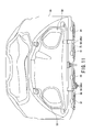
Fig. 1 is a left side view illustrating a motorcycle provided with an intake structure (intake device) according to an embodiment of the present invention; -
Fig. 2 is a left side view illustrating the intake structure of the motorcycle according to the embodiment of the present invention, from which a cowling is removed; -
Fig. 3 is a left side view illustrating the intake structure of the motorcycle according to the embodiment of the present invention, from which a vehicle frame is further removed; -
Fig. 4 is a perspective view illustrating the intake structure of the motorcycle according to the embodiment of the present invention; -
Fig. 5 is a plan view illustrating the intake structure of the motorcycle according to the embodiment of the present invention; -
Fig. 6 is a rear view illustrating a structure or layout around a throttle body of the intake structure of the motorcycle according to the embodiment of the present invention; -
Fig. 7 is a bottom view illustrating the intake structure of the motorcycle according to the embodiment of the present invention; -
Fig. 8 is a bottom view illustrating air ducts and an air cleaner box of the intake structure of the motorcycle according to the embodiment of the present invention; -
Fig. 9 is an illustrated vertical sectional view of the intake structure of the motorcycle according to the embodiment of the present invention; -
Fig. 10 is also an illustrated vertical sectional view of the intake structure of the motorcycle according to the embodiment of the present invention; and -
Fig. 11 is a front view illustrating the air cleaner box of the intake structure of the motorcycle according to the embodiment of the present invention. - In the following, an embodiment of an intake structure (or intake device) of a motorcycle according to the present invention will be described by reference to
Figs. 1 to 11 . It is further to be noted that terms "upper", "lower", "right", "left" and like terms showing direction are used herein with reference to the accompanying drawings or in a standing state of a motorcycle such as shown inFig. 1 . That is, for the following description of the embodiment of the present invention, a solid arrow F inFig. 1 is defined as a front (forward) side and a solid arrow R inFig. 1 is defined as a rear (rearward) side in a longitudinal direction of a motorcycle 1. A left-hand side as viewed from a rider of the motorcycle 1 is defined as a left side of the motorcycle 1, and an opposite side thereof is defined as a right side of the motorcycle 1. A head side of a rider of the motorcycle 1 is defined as an upper side of the motorcycle 1, and an opposite side thereof is defined as a lower side of the motorcycle 1. - As shown in
Fig. 1 , the motorcycle 1 includes avehicle body frame 2, anengine 3, asteering mechanism 5, afront wheel 6, a front-wheel suspension device 7, aswing arm 8, arear wheel 11, and a rear-wheel suspension device 12. - The
engine 3 is located below a front half portion of thevehicle body frame 2. Thesteering mechanism 5 is positioned at a front end portion of thevehicle body frame 2 to be swingable in a right and left direction. Thefront wheel 6 is disposed at a lower end portion of thesteering mechanism 5 and contacts the ground. The front-wheel suspension device 7 is interposed between thevehicle body frame 2 and thefront wheel 6. Theswing arm 8 is located at a rear portion of thevehicle body frame 2 to be swingable in a vertical direction. Therear wheel 11 is disposed at a rear end portion of theswing arm 8 and contacts the ground. The rear-wheel suspension device 12 is suspended between thevehicle body frame 2 and theswing arm 8. - The
vehicle body frame 2 is a twin-tube type frame, for example. Thevehicle body frame 2 includes asteering head pipe 13 disposed at the front end portion of thevehicle body frame 2, a right and left pair ofmain frames 15 branched so as to extend rearward at right and left thereof immediately after thesteering pipe 13, a pair of right andleft center frames 16 connected to rear end portions of themain frames 15 and extend downward, and a pair of right andleft seat rails 17 coupled to the rear end portions of themain frames 15 so as to extend slightly upward in a rearward direction of the vehicle body. - The
steering head pipe 13 swingably supports thesteering mechanism 5. - The
main frames 15 are branched immediately after thesteering head pipe 13 so as to slightly descend toward the vehicle rear side with a distance therebetween being gradually widened. Themain frames 15 are frames provided with function as a tank rail. Themain frames 15 support an aircleaner box 18 located above a front half portion thereof, and afuel tank 19 located above a rear half portion thereof. Themain frames 15 also support theengine 3 disposed below the main frames 15. - The center frames 16 hold a
pivot shaft 21 that extends in a vehicle width direction and swingably supports theswing arm 8. - The
engine 3 is located posterior to thefront wheel 6 and below themain frames 15 so as to occupy a center lower portion of the motorcycle 1. - The
steering mechanism 5 includes a steering shaft, not shown, in a manner of penetrating thesteering head pipe 13 and act as a swing center of the steering mechanism, a pair of right and leftfront forks 22 extending in a vertical direction, and a pair of right and left handle bars 23 respectively provided adjacent to upper ends of thefront forks 22. Each of the handle bars 23 includes ahandle grip 25, in which thehandle grip 25 disposed on the right side of the motorcycle 1 is athrottle grip 26. - The motorcycle 1 also includes a
cowling 27 having a streamline shape that covers at least one portion of the vehicle, for example, a vehicle body portion from a front portion to the center lower portion. Thecowling 27 reduces air resistance generated while the motorcycle 1 is running, and protects a rider from a running wind pressure. - The
cowling 27 includes afront cover 28, a pair of right and left side covers 31 covering side portions of theengine 3, an aircleaner cover 32 covering theair cleaner box 18, aseat cover 35 supporting aseat 33, and arear cover 36 covering the rear side of the vehicle body. - The
air cleaner box 18 accommodates anair cleaner 37 acting as an air filter that filters intake air into theengine 3. - The motorcycle 1 further includes a pair of right and left
air ducts 39 adapted to guide air to theair cleaner box 18 from asuction port 39 formed at a front end of thefront cover 28 and opened to the vehicle front side so as to guide the air to theair cleaner 37. -
Figs. 2 and3 are left side views illustrating an intake structure (device or mechanism) of the motorcycle according to the embodiment of the present invention. -
Fig. 2 is a view illustrating a region around theengine 3 from which thecowling 27 is removed, andFig. 3 is a view illustrating the region inFig. 2 from which thevehicle body frame 2 is further removed. - As shown in
Figs. 2 and3 , the motorcycle 1 includes thevehicle body frame 2, theengine 3 located below thevehicle body frame 2 in which a cylinder axis C is inclined forward, theair cleaner box 18 located above theengine 3 and themain frames 15, thefuel tank 19 disposed on a rear side of theair cleaner box 18 and athrottle body 41 adapted to guide intake air from theair cleaner box 18 to theengine 3. - The
engine 3 includes acylinder assembly 42 disposed immediately below theair cleaner box 18 and between themain frames 15, and acrank assembly 43 connected to a lower end of thecylinder assembly 42 and expands in a longitudinal direction of the vehicle body. - The
cylinder assembly 42 includes acylinder 45 having the cylinder axis C inclined forward, acylinder head 47 having anintake port 46 that guides the intake air into thecylinder 45, and ahead cover 48. - The
cylinder 45 is formed with a cylinder bore, not shown, that extends with the cylinder axis C being the center thereof. Thecylinder head 47 is connected to an upper end of thecylinder 45 to thereby close a top portion of thecylinder 45. Thecylinder head 47 is provided with an exhaust port, not shown, intake and exhaust valves, not shown, and valve mechanisms, also not shown, in addition to theintake port 46. The intake and exhaust valves and the valve train mechanism respectively open and close theintake port 46 and the exhaust port. Thehead cover 48 is a lid for thecylinder head 47 to close an upper end thereof. - The
crank assembly 43 includes a crankcase 51 that accommodates a crank shaft and a transmission, both not shown. - The crank
case 51 includes anupper case half 52 and alower case half 53 capable of vertically dividing thecrank case 51. The crankcase 51 is connected to thecylinder 45, that is, a lower end of thecylinder assembly 42 and expands in the longitudinal direction in a manner such that crank shaft is accommodated in a front half portion near to thecylinder 45, and the transmission is also accommodated therein on the rear side of the crank shaft. - Furthermore, the
engine 3 also includes anelectrical component 55 that is located on the rear side of thecylinder 45 and forms a valley-like space together with thecylinder 45. Theelectrical component 55 may be a power generator, for example. Theelectrical component 55 may be accommodated in thecrank case 51 or located outside thecrank case 51. - The
air cleaner box 18 includes alower half portion 56 that covers an upper side of thecylinder assembly 42 and is held between themain frames 15, and anupper half portion 57 that projects above themain frames 15 from thelower half portion 56. Theair cleaner box 18 also includes a front wall 59 of thelower half portion 56 in addition to theair cleaner 37. The front wall 59 has a pair of right and left airduct connection ports 58 through which running wind is introduced inside. - Since the air
duct connection ports 58 are formed in the front wall 59 of thelower half portion 56, themain frames 15 are provided with a pair of right and left throughholes 61 in which theair ducts 39 are arranged. - The
fuel tank 19 includes afront half portion 62 connected to a rear portion of theair cleaner box 18, and arear half portion 63 located under theseat 33. Thefront half portion 62 of thefuel tank 19 extends upward to a higher position than therear half portion 63, and therear half portion 63 extends rearward, so that thefuel tank 19 ensures the maximum capacity. Thefront half portion 62 covers a rear half portion of thecrank case 51. - The
throttle body 41 as an intake system of theengine 3 is located below theair cleaner box 18 on the rear side of the engine 3 (more specifically, the cylinder head 47). Thethrottle body 41 is connected to a rear surface of thecylinder head 47 via anintake pipe 64 and leads to theintake port 46. Thethrottle body 41 is also held between the right and leftmain frames 15. Theintake pipe 64 is a short pipe made of rubber and flexibly supports thethrottle body 41 relative to theengine 3. - An
exhaust pipe 65 as an exhaust system of theengine 3 is connected to a front surface of thecylinder head 47, leads to the exhaust port, passes sequentially around a front surface and a bottom surface of theengine 3 and extends toward the vehicle rear side. - A cooling system of the
engine 3 includes aradiator 66 and anoil cooler 67. Theradiator 66 spreads so as to cover a front side of thecylinder assembly 42. Theoil cooler 67 spreads so as to cover a front side of thecrank case 51 at a portion below theradiator 66. -
Fig. 4 is a perspective view illustrating the intake structure of the motorcycle according to the embodiment of the present invention, andFig. 5 is a plan view illustrating the intake structure of the motorcycle. - As shown in
Figs. 4 and5 , the intake structure of the motorcycle 1 includes an electronically controlled throttle that drives opening and closing of athrottle valve 71 by anelectric motor 68 to thereby adjust a flow rate of intake air. - The electronically controlled throttle acts to convert an operation amount of the
throttle grip 26 into a rotation angle of a throttle pulley 72, which is measured by an accelerator position sensor 73. A duty ratio of theelectric motor 68 is controlled according to a measurement amount of the accelerator position sensor 73. The opening and closing of thethrottle valve 71 is controlled by driving theelectric motor 68. Thus, the electronically controlled throttle controls the driving of thethrottle valve 71 in accordance with the operation amount of thethrottle grip 26. - The operation amount of the
throttle grip 26 corresponds to a twisting angle of thethrottle grip 26, and specifically, to a throttle operation amount. Acable 75 extends from a handle 76 to the throttle pulley 72 so as to transmit the operation amount of thethrottle grip 26 to the throttle pulley 72. - The
throttle body 41 is provided with a plurality of, for example, four throttle bores 77 corresponding to the number of cylinder bores (i.e., the number of cylinders) of theengine 3. The throttle bores 77 are arranged in the width direction of the vehicle (i.e., the vehicle body frame 2), and the throttle bores 77 are communicated respectively with the cylinder bores via theintake ports 46. - The
throttle body 41 is also provided with thethrottle valve 71 located within each of the throttle bores 77 between theair cleaner box 18 and thecylinder head 47 so as to adjust the flow rate of intake air, and avalve shaft 78 that penetrates the plurality of throttle bores 77 so as to extend in the vehicle width direction of thevehicle body frame 2. - The
throttle body 41 further includes a gap between a half body provided with the left-side two throttle bores 77 and another half body provided with the right-side two throttle bores 77. - The
valve shaft 78 is a rotation center of a valve body of thethrottle valve 71, and twovalve shafts 78 are provided. Each of thevalve shafts 78 constitutes the rotation center of the valve bodies of the left-side twothrottle valves 71 or the right-side twothrottle valves 71 with respect to the four throttle bores 77 arranged in the vehicle width direction. The twovalve shafts 78 lie on a substantially straight line. - The intake structure of the motorcycle 1 of the present embodiment also includes the
electric motor 68, and a measuring device 81. Theelectric motor 68 is disposed on the rear side of thecylinder head 47 and operates to open and/or close thethrottle valves 71. The measuring device 81 is located on the rear side of thethrottle body 41 and rotates about a rotational shaft parallel to thevalve shaft 78 to thereby measure the throttle operation amount. - The
electric motor 68 is more specifically located in a projection area or space on the rear side of thecylinder head 47. That is, the projection area or space means a shadow area when light is applied to the cylinder head and exists the outermost shape of the cylinder head extending in the longitudinal direction thereof. Theelectric motor 68 is supported at a rear portion of thethrottle body 41. Twoelectric motors 68 are disposed in a manner spaced apart from each other in the vehicle width direction. Each of theelectric motors 68 operates to open and/or close the left-side two throttle bores 77 or the right-side two throttle bores 77 with respect to the four throttle bores 77 arranged in the vehicle width direction. Each of theelectric motors 68 is located on the rear side of an intermediate position between the two throttle bores 77 to be opened and closed. - The two
electric motors 68 include output shafts which lie on a substantially straight line in parallel to thevalve shaft 78. The output shafts extend in an external direction of the vehicle. - The
electric motors 68 are respectively connected to thevalve shafts 78 sequentially through aplanetary gear 82 connected to the output shaft of theelectric motor 68 and alink mechanism 83 connecting an output shaft of theplanetary gear 82 and thevalve shaft 78. Theplanetary gear 82 lies on an output axis of each of theelectric motors 68 and is located on the rear side of each of the throttle bores 77 positioned outside of the vehicle in the vehicle width direction. - A pair of
link mechanisms 83 is arranged respectively on right and left sides of thethrottle body 41. Each of thelink mechanisms 83 is suspended between theplanetary gear 82 and thevalve shaft 78. Theelectric motors 68 rotationally drive thevalve shafts 78 through theplanetary gears 82 and thelink mechanisms 83, thereby opening and/or closing thethrottle valves 71. - The measuring device 81 includes the throttle pulley 72 arranged on the rear side of the
electric motor 68 and the accelerator position sensor 73 that measures the rotation angle of the throttle pulley 72. The measuring device 81 is supported by thethrottle body 41. - The throttle pulley 72 is located on the rear side of the
electric motor 68 that is located further on the rear side of the intermediate position between the left-side two throttle bores 77 and is configured to rotate about the rotational shaft parallel to thevalve shaft 78 to thereby measure the throttle operation amount. - The accelerator position sensor 73 includes a pair of accelerator position sensors 73 at both ends of the throttle pulley 72 with the rotational shaft of the throttle pulley 72 being interposed therebetween.
- The
cable 75 extends through a gap between the throttle bores 77 adjacent to each other in a plan view and transmits an operation of the throttle from thethrottle grip 26 to the measuring device 81. More specifically, thecable 75 is connected to the throttle pulley 72 located on the rear side of the intermediate position between the left-side two throttle bores 77 by extending through an upper portion or a lower portion of the gap between the left-side two throttle bores 77. Thecable 75 thereby transmits the throttle operation. Thus, thecable 75 does not interfere with thelink mechanisms 83 on the right and left sides of thethrottle body 41. - The electronically controlled throttle also includes a
throttle position sensor 79 that measures an opening degree of thethrottle valve 71, and asecond link mechanism 80 that transmits an opening degree of thevalve shaft 78 to thethrottle position sensor 79. - The
throttle position sensor 79 includes a right and left pair ofthrottle position sensors 79. Thethrottle position sensors 79 are respectively located on the rear side of the two throttle bores 77 on a vehicle center side and on the vehicle center side from theelectric motors 68. - The
second link mechanism 80 is disposed in the gap between the left-side two throttle bores 77 and the right-side two throttle bores 77 in the half bodies of thethrottle body 41. Thesecond link mechanism 80 is suspended between thethrottle position sensor 79 and thevalve shaft 78. -
Fig. 6 is a back side view illustrating a region around the throttle body of the intake structure of the motorcycle according to the embodiment of the present invention. - As shown in
Figs. 3 ,4 and6 , the intake structure of the motorcycle 1 according to the present embodiment includes afuel supply pipe 85 that is arranged between thecylinder 45 and theelectric motor 68 and connects thefuel tank 19 and thecylinder head 47. - The
fuel supply pipe 85 includes a cylinder head-side connection end 86 located on the rear side of and closest to thecylinder head 47 and below theelectric motor 68. Theconnection end 86 is connected to thecylinder head 47. The cylinder head-side connection end 86 is a branch pipe that extends in the width direction of thecylinder head 47 and branches so as to supply a fuel to the respective cylinders. - The
fuel supply pipe 85 is located in the valley-shaped space formed by thecylinder 45 and theelectrical component 55. - The
electric motor 68 of the electronically controlled throttle is located below the top portion of thethrottle body 41. - The
fuel supply pipe 85, theelectric motor 68 and the throttle pulley 72 of the electronically controlled throttle are disposed in the valley-shaped space formed by thecylinder 45 and theelectrical component 55 in a manner such that the cylinder head-side connection end 86 of thefuel supply pipe 85, an output axis Cm of theelectric motor 68, and a rotation center line Cp of the throttle pulley 72 are arranged so as to constitute an inverted triangle shape T in the side view of the vehicle. At least one side of the inverted triangle shape is arranged along a wall surface of theengine 3 or a wall surface of theelectrical component 55 that defines the valley-shaped space formed by thecylinder 45 and theelectrical component 55. - The axis of the
valve shaft 78, the output axis Cm of theelectric motor 68, and the rotation center line Cp of the throttle pulley 72 lie on a substantially same plane, and are substantially perpendicular to a center line of the throttle bore 77. - The output axis Cm of the
electric motor 68 and the extending direction of the cylinder head-side connection end 86 are located within a plane substantially parallel to the center line of the throttle bore 77. - Hereunder, the
air ducts 39, theair cleaner box 18 and the electronically controlled throttle will be described with reference toFigs. 7 to 12 , in whichFig. 7 is the bottom view illustrating the intake structure of the motorcycle,Fig. 8 is the bottom view illustrating the air ducts and the air cleaner box of the intake structure of the motorcycle,Fig. 9 is a vertical sectional view illustrating the intake structure of the motorcycle along a line IX-IX inFig. 7 ,Fig. 10 is a vertical sectional view illustrating the intake structure of the motorcycle taken along a line X-X inFig. 7 , andFig. 11 is a front view illustrating the air cleaner box of the intake structure of the motorcycle. - As shown in
Figs. 7 to 11 , the intake structure of the motorcycle 1 according to the present embodiment includes abottom wall 89 of theair cleaner box 18. Thebottom wall 89 is formed with awind guide groove 88 for guiding the running wind flowing into the gap between thecylinder head 47 and theair cleaner box 18 to the vicinity of theelectric motor 68 from the front side of thethrottle body 41. - The
bottom wall 89 of theair cleaner box 18 faces thethrottle body 41 or theengine 3, and is formed with fouropenings 91 communicating with the throttle bores 77 in addition to thewind guide groove 88. The fouropenings 91 are arranged in the vehicle width direction in a manner similar to the throttle bores 77. - The
wind guide groove 88 extends in the longitudinal direction between the throttle bores 77 adjacent to each other in plan view. Specifically, twowind guide grooves 88 are formed, in which one of thewind guide grooves 88a extends in the longitudinal direction between the left-side twoopenings 91 and the other one of thewind guide grooves 88b extends in the longitudinal direction between the right-side twoopenings 91. Thus, thewind guide groove 88a extends in the longitudinal direction at the intermediate position between the two throttle bores 77 on the left side of the vehicle, and thewind guide groove 88b extends in the longitudinal direction at the intermediate position between the two throttle bores 77 on the right side of the vehicle in plan view of the vehicle. - The
wind guide groove 88a is a cutout groove in which thecable 75 transmitting the throttle operation from thethrottle grip 26 to the measuring device 81 is arranged. - The
bottom wall 89 has a firstwind guide hole 92 formed on the front side of thethrottle body 41 and on the rear side of the front end of thecylinder head 47 so as to guides the air to thewind guide groove 88 from the interior of theair cleaner box 18. - The first
wind guide hole 92 is positioned on the upstream side (so-called dirty side) of theair cleaner 37 in the air flowing in theair duct 39 and aircleaner box 18 so as to guide air not passing through theair cleaner 37 thewind guide groove 88. The firstwind guide hole 92 includes a pair of right and left openings which lie on extension lines of thewind guide grooves 88, respectively. - The intake structure of the motorcycle 1 is also formed with a
bottom wall 95 of each of theair ducts 39. Thebottom wall 95 has a secondwind guide hole 93 located on the front side of thethrottle body 41 so as to guide the air from the interior of theair duct 39 to thewind guide groove 88. - In order to efficiently introduce the running wind into the
air cleaner box 18, theair ducts 39 are opened at a front end of the vehicle, and branched to right and left sides with a distance therebetween being gradually widened so as to bypass thesteering head pipe 13 and thesteering mechanism 5. After passing through peripheries of thesteering head pipe 13 and thesteering mechanism 5, theair ducts 39 approach each other and are connected to the airduct connection ports 58 of theair cleaner box 18. - Each of the second
wind guide hole 93 is located on the rear side of theradiator 66 which is located in front of thecylinder 45. The secondwind guide hole 93 is formed with a pair of right and left openings which are located outside the extension line of thewind guide grooves 88 in the vehicle width direction, respectively. - The intake structure of the motorcycle 1 having the configuration as described above introduces the running wind from the
air ducts 39 into theair cleaner box 18 and sends the intake air to theengine 3 through thethrottle body 41. - The intake structure of the motorcycle 1 includes the electronically controlled throttle performing the opening/closing operation of the
throttle valve 71 by theelectric motor 68 to thereby adjust the flow rate of intake air. Theelectric motor 68 performs the opening/closing operation of thethrottle valve 71 by utilizing the rotation angle of the throttle pulley 72 measured by the accelerator position sensor 73 as the operation amount of thethrottle grip 26. Thus, if the throttle pulley 72 is rotated due to vibrations caused by the running of the motorcycle 1 or vibrations generated by theengine 3, the accelerator position sensor 73 will erroneously measure the operation amount of thethrottle grip 26, thus being defective. - To overcome such defect, according to the intake structure of the motorcycle 1 of the present embodiment, the
flexible intake pipe 64 made of rubber is interposed between thethrottle body 41 and theengine 3 so as to protect thethrottle body 41 from the suffering of the vibrations caused by the running motorcycle 1 or theengine 3 being operated, and eventually suppresses the vibrations of the measuring device 81 supported by the throttle body 41 (Fig. 3 ). - According to the intake structure of the present embodiment, since the vibrations of the measuring device 81 can be suppressed, the throttle pulley 72 is prevented from being rotated due to the vibrations. Accordingly, the accelerator position sensor 73 can perform measurement with higher reliability.
- In the intake structure of the motorcycle 1 according to the present embodiment, the throttle pulley 72 is arranged on the rear side of the
throttle body 41 or theelectric motor 68. Thus, the throttle pulley 72 is not exposed to outside, and hence, the outer appearance of the motorcycle is not spoiled. - In addition, the intake structure of the motorcycle 1 according to the present embodiment can also avoid an increase in the vehicle width.
- Furthermore, in the intake structure of the motorcycle 1 according to the present embodiment, since the throttle pulley 72 is arranged on the rear side of the gap between the left-side two throttle bores 77, and the
cable 75 is arranged in thewind guide groove 88a, thecable 75 can be connected to thethrottle grip 26 without bending thecable 75 in a complicated shape or in a shape with a small curvature radius. Accordingly, with the intake structure of the motorcycle 1 of the present embodiment, thethrottle grip 26 can offer a rider a natural and better operational feeling. - As described hereinbefore, according to the intake structure of the motorcycle 1 of the present embodiment, the operation amount of the
throttle grip 26 can be measured with high reliability even in a vibration environment and the outer appearance of the vehicle can be prevented from being spoiled, thus being advantageous. - Incidentally, in another aspect of the intake structure of the motorcycle 1 of the present embodiment, the following characteristic structure and function may be provided.
- That is, with reference to
Figs. 1 to 6 , and particularly,Figs. 4 to 6 , the intake structure of the motorcycle 1 includes the electronically controlled throttle that drives the opening and closing of thethrottle valve 71 by theelectric motor 68 to thereby adjust the flow rate of intake air, as described hereinbefore. - In the intake structure of the motorcycle 1, the
electric motor 68 is preferably arranged as close as possible to thethrottle body 41 so as to reduce a capacity required to arrange the electronically controlled throttle. However, when theelectric motor 68 is arranged close to thethrottle body 41, theelectric motor 68 is also arranged close to theengine 3. Thus, theelectric motor 68 is apt to be affected by heat generated by theengine 3 or heat generated by theelectric motor 68 itself, thus being defective. - To avoid such defect, according to the intake structure of the motorcycle 1 of the present embodiment, the fuel supply pipe 85 (more specifically, the cylinder head-side connection end 86) is arranged between the
cylinder 45 and theelectric motor 68 so as to block the heat generated by theengine 3. Theelectric motor 68 can hence be arranged close to thethrottle body 41. Further, during the running of the motorcycle 1, since a new fuel always passes through thefuel supply pipe 85, thefuel supply pipe 85 can effectively block the heat generated by theengine 3. - In the intake structure of the motorcycle 1 according to the present embodiment, the
electric motor 68 is arranged in the projection area or space on the rear side of thecylinder head 47, so that it is not necessary to ensure a capacity to arrange theelectric motor 68 between thehead cover 48 and theair cleaner box 18. Thus, there is no need to reduce a volume of theair cleaner box 18. - In the intake structure of the motorcycle 1 of the present embodiment, the fuel supply pipe 85 (more specifically, the cylinder head-side connection end 86) is arranged in the valley-shaped space formed by the
cylinder 45 and theelectrical component 55. Thus, the valley-shaped space is effectively usable. Accordingly, the electronically controlled throttle and a fuel supply system can be compactly arranged. - In the intake structure of the motorcycle 1 according to the present embodiment, since the
electric motor 68 is arranged below the top portion of thethrottle body 41, theair cleaner box 18 and thefuel tank 19 can be prevented from being reduced in capacity. - In the meantime, if the
cable 75 passes through the vicinity of thecylinder 45, thecable 75 expands and contracts due to the heat generated by theengine 3, and in such a case, thecable 75 may not accurately transmit the operation amount of thethrottle grip 26 due to an error factor such as a bias between a hot state and a cold state, which may result in a cause of an error in measurement by the measuring device 81. In order to avoid such defect, according to the intake structure of the motorcycle 1 of the present embodiment, the throttle pulley 72 is arranged on the rear side of theelectric motor 68, thereby arranging thecable 75 along a path away from thecylinder 45. The throttle pulley 72 is also arranged at a position further apart from theengine 3 than theelectric motor 68. Accordingly, the measuring device 81 is prevented from making an error in measurement. - Furthermore, in the intake structure of the motorcycle 1 according to the present embodiment, the
fuel supply pipe 85, theelectric motor 68, and the throttle pulley 72 are located in the valley-shaped space formed by thecylinder 45 and theelectrical component 55 in a manner such that the cylinder head-side connection end 86 of thefuel supply pipe 85, the output axis of theelectric motor 68, and the rotation center line of the throttle pulley 72 are arranged in an inverted triangle shape, and at least one side of the inverted triangle shape is arranged along the wall surface of theengine 3 or a wall surface of theelectrical component 55 that defines the valley-shaped space. The valley-shaped space portion is thereby effectively used. Accordingly, the intake structure is effectively arranged without forming a dead space between theengine 3 and theair cleaner box 18 to thereby provide the intake structure having a compact size. - As described above, with the intake structure of the motorcycle 1 of the present embodiment of the above aspect, a capacity of a region to arrange the
throttle body 41 and theelectric motor 68 can be reduced by closely arranging thethrottle body 41 and theelectric motor 68. - It is further to be noted that the present invention is not limited to the described embodiments and many other changes and modifications or alternations may be made without departing from the scopes of the appended claims.
Claims (9)
- An intake structure of a motorcycle having a head pipe, a vehicle body frame including a pair of left and right main frames extending rearward from the head pipe, and an engine disposed below the vehicle body frame and including a cylinder having an inclined cylinder axis, the intake structure comprising:an air cleaner box disposed above the engine and the main frames;a throttle body provided with a plurality of throttle bores formed and arranged in a vehicle width direction of the vehicle body frame and a valve shaft penetrating the throttle bores so as to extend in the vehicle width direction of the vehicle body frame, the throttle body being located on a rear side of the engine and between the pair of left and right main frames and configured to guide intake air from the air cleaner box to the engine; anda measuring device located on a rear side of the throttle body and configured to rotate about a rotational shaft parallel to the valve shaft to thereby measure a throttle operation amount.
- The intake structure of the motorcycle according to claim 1, wherein the measuring device includes a throttle pulley located on a rear side of a gap between adjacent throttle bores and configured to rotate about the rotational shaft to measure the throttle operation amount, and a cable that transmits a throttle operation from a throttle grip to the throttle pulley through the gap in a plan view.
- The intake structure of the motorcycle according to claim 2, wherein the air cleaner box is formed, in a bottom surface thereof so as to face the throttle body or engine, with a cutout groove in which is arranged.
- An intake structure of a motorcycle having a head pipe, a vehicle body frame extending rearward from the head pipe, a fuel tank, and an engine disposed below the vehicle body frame and including a cylinder having an inclined cylinder axis and a cylinder head closing a top portion of the cylinder, the intake structure comprising:an air cleaner box disposed above the engine and the main frames and on a rear side of the fuel tank;a throttle body including a throttle valve located between the air cleaner box and the cylinder head and configured to adjust a flow rate of an intake air, the throttle body being located below the air cleaner box on a rear side of the cylinder head;an electric motor located in a projected area on the rear side of the cylinder head and configured to open and close the throttle valve; anda fuel supply pipe disposed between the cylinder and the electric motor and connecting the fuel tank and the cylinder head.
- The intake structure of the motorcycle according to claim 4, wherein the electric motor is supported at a rear portion of the throttle body, the fuel supply pipe disposed below the electric motor and connected to the cylinder head, and includes a connection end to be connected to the cylinder head, and extending directions of an output shaft of the electric motor and the connection end of the fuel supply pipe lie within a plane substantially parallel to a center line of a throttle bore that accommodates the throttle valve.
- The intake structure of the motorcycle according to claim 4, further comprising an electrical component disposed on a rear side of the cylinder so as to define a valley-shaped space together with the cylinder, in which the fuel supply pipe is arranged.
- The intake structure of the motorcycle according to claim 6, wherein the electric motor is located below a top portion of the throttle body.
- The intake structure of the motorcycle according to claim 6, further comprising a throttle pulley disposed on a rear side of the electric motor and configured to measure a throttle operation amount.
- The intake structure of the motorcycle according to claim 8, wherein the fuel supply pipe, the electric motor, and the throttle pulley are disposed within in the valley-shaped space such that the connection end of the fuel supply pipe, the output axis of the electric motor, and a rotation center line of the throttle pulley are arranged so as to provide an inverted triangle shape in side view of a vehicle, and at least one side of the inverted triangle shape is arranged along a wall surface of the engine or a wall surface of the electrical component that defines the valley-shaped space.
Applications Claiming Priority (2)
| Application Number | Priority Date | Filing Date | Title |
|---|---|---|---|
| JP2011120690A JP5672151B2 (en) | 2011-05-30 | 2011-05-30 | Intake structure of motorcycle |
| JP2011120691A JP5672152B2 (en) | 2011-05-30 | 2011-05-30 | Intake structure of motorcycle |
Publications (2)
| Publication Number | Publication Date |
|---|---|
| EP2530285A1 true EP2530285A1 (en) | 2012-12-05 |
| EP2530285B1 EP2530285B1 (en) | 2016-03-16 |
Family
ID=46208324
Family Applications (1)
| Application Number | Title | Priority Date | Filing Date |
|---|---|---|---|
| EP12170056.1A Active EP2530285B1 (en) | 2011-05-30 | 2012-05-30 | Intake structure of motorcycle |
Country Status (3)
| Country | Link |
|---|---|
| US (1) | US8714138B2 (en) |
| EP (1) | EP2530285B1 (en) |
| ES (1) | ES2566052T3 (en) |
Families Citing this family (4)
| Publication number | Priority date | Publication date | Assignee | Title |
|---|---|---|---|---|
| JP5901255B2 (en) * | 2011-11-30 | 2016-04-06 | 株式会社ミクニ | Multiple throttle device |
| JP5949074B2 (en) * | 2012-04-05 | 2016-07-06 | スズキ株式会社 | Intake system of internal combustion engine |
| WO2014075091A2 (en) | 2012-11-12 | 2014-05-15 | Indian Motorcycle International, LLC | Two-wheeled vehicle |
| JP5967447B2 (en) * | 2013-12-10 | 2016-08-10 | 本田技研工業株式会社 | Intake device for saddle-ride type vehicles |
Citations (6)
| Publication number | Priority date | Publication date | Assignee | Title |
|---|---|---|---|---|
| EP0867608A2 (en) * | 1997-03-27 | 1998-09-30 | Yamaha Hatsudoki Kabushiki Kaisha | Air intake apparatus for a four-cycle internal combustion engine |
| US6202626B1 (en) * | 1997-01-31 | 2001-03-20 | Yamaha Hatsudoki Kabushiki Kaisha | Engine having combustion control system |
| US20020050268A1 (en) * | 2000-10-27 | 2002-05-02 | Hiromi Deguchi | Air intake control device of fuel injection engine |
| JP2008274925A (en) | 2007-03-30 | 2008-11-13 | Honda Motor Co Ltd | Accelerator position sensor arrangement structure for motorcycle |
| DE102008063210A1 (en) * | 2008-03-28 | 2009-10-01 | Honda Motor Co., Ltd. | Intake air control system of a V-type internal combustion engine |
| JP2010223004A (en) | 2009-03-19 | 2010-10-07 | Honda Motor Co Ltd | Intake control device for vehicular engine |
Family Cites Families (8)
| Publication number | Priority date | Publication date | Assignee | Title |
|---|---|---|---|---|
| US5577570A (en) * | 1992-04-09 | 1996-11-26 | Yamaha Hatsudoki Kabushiki Kaisha | Wind introducing system for motorcycle |
| JP4167635B2 (en) * | 2004-08-26 | 2008-10-15 | 本田技研工業株式会社 | Fuel supply device for V-type engine for vehicle |
| JP4334493B2 (en) * | 2005-03-17 | 2009-09-30 | 株式会社ケーヒン | Fuel supply pipe structure in a multiple throttle body with two fuel injection valves |
| US7779950B2 (en) * | 2005-05-02 | 2010-08-24 | Polaris Industries Inc. | Integrated frame and air box method and apparatus |
| JP2008230492A (en) * | 2007-03-22 | 2008-10-02 | Suzuki Motor Corp | Fuel feeding device for motorcycle |
| JP2009092018A (en) * | 2007-10-10 | 2009-04-30 | Yamaha Motor Co Ltd | Engine unit and vehicle equipped with same |
| JP5339612B2 (en) * | 2009-05-22 | 2013-11-13 | 本田技研工業株式会社 | Saddle riding vehicle |
| JP5352567B2 (en) * | 2009-11-10 | 2013-11-27 | 株式会社ミクニ | Fuel injection device |
-
2012
- 2012-05-29 US US13/482,764 patent/US8714138B2/en active Active
- 2012-05-30 EP EP12170056.1A patent/EP2530285B1/en active Active
- 2012-05-30 ES ES12170056.1T patent/ES2566052T3/en active Active
Patent Citations (7)
| Publication number | Priority date | Publication date | Assignee | Title |
|---|---|---|---|---|
| US6202626B1 (en) * | 1997-01-31 | 2001-03-20 | Yamaha Hatsudoki Kabushiki Kaisha | Engine having combustion control system |
| EP0867608A2 (en) * | 1997-03-27 | 1998-09-30 | Yamaha Hatsudoki Kabushiki Kaisha | Air intake apparatus for a four-cycle internal combustion engine |
| US20020050268A1 (en) * | 2000-10-27 | 2002-05-02 | Hiromi Deguchi | Air intake control device of fuel injection engine |
| JP2002129987A (en) | 2000-10-27 | 2002-05-09 | Suzuki Motor Corp | Air suction control device for fuel-injected engine |
| JP2008274925A (en) | 2007-03-30 | 2008-11-13 | Honda Motor Co Ltd | Accelerator position sensor arrangement structure for motorcycle |
| DE102008063210A1 (en) * | 2008-03-28 | 2009-10-01 | Honda Motor Co., Ltd. | Intake air control system of a V-type internal combustion engine |
| JP2010223004A (en) | 2009-03-19 | 2010-10-07 | Honda Motor Co Ltd | Intake control device for vehicular engine |
Also Published As
| Publication number | Publication date |
|---|---|
| ES2566052T3 (en) | 2016-04-08 |
| EP2530285B1 (en) | 2016-03-16 |
| US20120304965A1 (en) | 2012-12-06 |
| US8714138B2 (en) | 2014-05-06 |
Similar Documents
| Publication | Publication Date | Title |
|---|---|---|
| JP4799352B2 (en) | Electronic throttle control device for V-type internal combustion engine for vehicle | |
| ES2353911T3 (en) | STRUCTURE OF THE ADMISSION SYSTEM OF AN INTERNAL COMBUSTION ENGINE OF TYPE V. | |
| US7168517B2 (en) | Throttle valve opening control device and layout structure thereof | |
| EP2530285B1 (en) | Intake structure of motorcycle | |
| JP4544603B2 (en) | Throttle control device for motorcycle engine | |
| JP5215092B2 (en) | Engine and vehicle equipped with this | |
| ES2538699T3 (en) | Admission control device | |
| CN103423003B (en) | The Intaker controller of motorcycle | |
| JP2009197816A (en) | Engine | |
| JP4476144B2 (en) | Arrangement structure of idle air control device for internal combustion engine | |
| JP2013108457A (en) | Arrangement structure for fuel injection device of motorcycle | |
| JP2011025763A (en) | Motorcycle | |
| JP5672152B2 (en) | Intake structure of motorcycle | |
| JP5086858B2 (en) | Internal combustion engine | |
| JP4892540B2 (en) | Throttle device | |
| JP5672151B2 (en) | Intake structure of motorcycle | |
| JP5355673B2 (en) | engine | |
| JP2012246876A (en) | Intake structure of motorcycle | |
| JP5068244B2 (en) | Throttle device | |
| JP5768549B2 (en) | Motorcycle electrical component arrangement structure | |
| JP4916563B2 (en) | Throttle control device for motorcycle engine | |
| JP7401407B2 (en) | engine throttle device | |
| JP5143275B2 (en) | engine | |
| WO2022014021A1 (en) | Engine intake device | |
| JP4916530B2 (en) | engine |
Legal Events
| Date | Code | Title | Description |
|---|---|---|---|
| PUAI | Public reference made under article 153(3) epc to a published international application that has entered the european phase |
Free format text: ORIGINAL CODE: 0009012 |
|
| 17P | Request for examination filed |
Effective date: 20120530 |
|
| AK | Designated contracting states |
Kind code of ref document: A1 Designated state(s): AL AT BE BG CH CY CZ DE DK EE ES FI FR GB GR HR HU IE IS IT LI LT LU LV MC MK MT NL NO PL PT RO RS SE SI SK SM TR |
|
| AX | Request for extension of the european patent |
Extension state: BA ME |
|
| RBV | Designated contracting states (corrected) |
Designated state(s): AL AT BE BG CH CY CZ DE DK EE ES FI FR GB GR HR HU IE IS IT LI LT LU LV MC MK MT NL NO PL PT RO RS SE SI SK SM TR |
|
| GRAP | Despatch of communication of intention to grant a patent |
Free format text: ORIGINAL CODE: EPIDOSNIGR1 |
|
| INTG | Intention to grant announced |
Effective date: 20150901 |
|
| GRAS | Grant fee paid |
Free format text: ORIGINAL CODE: EPIDOSNIGR3 |
|
| GRAA | (expected) grant |
Free format text: ORIGINAL CODE: 0009210 |
|
| AK | Designated contracting states |
Kind code of ref document: B1 Designated state(s): AL AT BE BG CH CY CZ DE DK EE ES FI FR GB GR HR HU IE IS IT LI LT LU LV MC MK MT NL NO PL PT RO RS SE SI SK SM TR |
|
| REG | Reference to a national code |
Ref country code: GB Ref legal event code: FG4D |
|
| REG | Reference to a national code |
Ref country code: CH Ref legal event code: EP |
|
| REG | Reference to a national code |
Ref country code: IE Ref legal event code: FG4D |
|
| REG | Reference to a national code |
Ref country code: ES Ref legal event code: FG2A Ref document number: 2566052 Country of ref document: ES Kind code of ref document: T3 Effective date: 20160408 |
|
| REG | Reference to a national code |
Ref country code: AT Ref legal event code: REF Ref document number: 781470 Country of ref document: AT Kind code of ref document: T Effective date: 20160415 |
|
| REG | Reference to a national code |
Ref country code: DE Ref legal event code: R096 Ref document number: 602012015583 Country of ref document: DE |
|
| REG | Reference to a national code |
Ref country code: NL Ref legal event code: MP Effective date: 20160316 |
|
| REG | Reference to a national code |
Ref country code: LT Ref legal event code: MG4D |
|
| PG25 | Lapsed in a contracting state [announced via postgrant information from national office to epo] |
Ref country code: FI Free format text: LAPSE BECAUSE OF FAILURE TO SUBMIT A TRANSLATION OF THE DESCRIPTION OR TO PAY THE FEE WITHIN THE PRESCRIBED TIME-LIMIT Effective date: 20160316 Ref country code: HR Free format text: LAPSE BECAUSE OF FAILURE TO SUBMIT A TRANSLATION OF THE DESCRIPTION OR TO PAY THE FEE WITHIN THE PRESCRIBED TIME-LIMIT Effective date: 20160316 Ref country code: NO Free format text: LAPSE BECAUSE OF FAILURE TO SUBMIT A TRANSLATION OF THE DESCRIPTION OR TO PAY THE FEE WITHIN THE PRESCRIBED TIME-LIMIT Effective date: 20160616 Ref country code: GR Free format text: LAPSE BECAUSE OF FAILURE TO SUBMIT A TRANSLATION OF THE DESCRIPTION OR TO PAY THE FEE WITHIN THE PRESCRIBED TIME-LIMIT Effective date: 20160617 |
|
| REG | Reference to a national code |
Ref country code: AT Ref legal event code: MK05 Ref document number: 781470 Country of ref document: AT Kind code of ref document: T Effective date: 20160316 |
|
| PG25 | Lapsed in a contracting state [announced via postgrant information from national office to epo] |
Ref country code: RS Free format text: LAPSE BECAUSE OF FAILURE TO SUBMIT A TRANSLATION OF THE DESCRIPTION OR TO PAY THE FEE WITHIN THE PRESCRIBED TIME-LIMIT Effective date: 20160316 Ref country code: NL Free format text: LAPSE BECAUSE OF FAILURE TO SUBMIT A TRANSLATION OF THE DESCRIPTION OR TO PAY THE FEE WITHIN THE PRESCRIBED TIME-LIMIT Effective date: 20160316 Ref country code: LT Free format text: LAPSE BECAUSE OF FAILURE TO SUBMIT A TRANSLATION OF THE DESCRIPTION OR TO PAY THE FEE WITHIN THE PRESCRIBED TIME-LIMIT Effective date: 20160316 Ref country code: BE Free format text: LAPSE BECAUSE OF NON-PAYMENT OF DUE FEES Effective date: 20160531 Ref country code: LV Free format text: LAPSE BECAUSE OF FAILURE TO SUBMIT A TRANSLATION OF THE DESCRIPTION OR TO PAY THE FEE WITHIN THE PRESCRIBED TIME-LIMIT Effective date: 20160316 Ref country code: SE Free format text: LAPSE BECAUSE OF FAILURE TO SUBMIT A TRANSLATION OF THE DESCRIPTION OR TO PAY THE FEE WITHIN THE PRESCRIBED TIME-LIMIT Effective date: 20160316 |
|
| PG25 | Lapsed in a contracting state [announced via postgrant information from national office to epo] |
Ref country code: PL Free format text: LAPSE BECAUSE OF FAILURE TO SUBMIT A TRANSLATION OF THE DESCRIPTION OR TO PAY THE FEE WITHIN THE PRESCRIBED TIME-LIMIT Effective date: 20160316 Ref country code: EE Free format text: LAPSE BECAUSE OF FAILURE TO SUBMIT A TRANSLATION OF THE DESCRIPTION OR TO PAY THE FEE WITHIN THE PRESCRIBED TIME-LIMIT Effective date: 20160316 Ref country code: IS Free format text: LAPSE BECAUSE OF FAILURE TO SUBMIT A TRANSLATION OF THE DESCRIPTION OR TO PAY THE FEE WITHIN THE PRESCRIBED TIME-LIMIT Effective date: 20160716 |
|
| PG25 | Lapsed in a contracting state [announced via postgrant information from national office to epo] |
Ref country code: SM Free format text: LAPSE BECAUSE OF FAILURE TO SUBMIT A TRANSLATION OF THE DESCRIPTION OR TO PAY THE FEE WITHIN THE PRESCRIBED TIME-LIMIT Effective date: 20160316 Ref country code: CZ Free format text: LAPSE BECAUSE OF FAILURE TO SUBMIT A TRANSLATION OF THE DESCRIPTION OR TO PAY THE FEE WITHIN THE PRESCRIBED TIME-LIMIT Effective date: 20160316 Ref country code: RO Free format text: LAPSE BECAUSE OF FAILURE TO SUBMIT A TRANSLATION OF THE DESCRIPTION OR TO PAY THE FEE WITHIN THE PRESCRIBED TIME-LIMIT Effective date: 20160316 Ref country code: PT Free format text: LAPSE BECAUSE OF FAILURE TO SUBMIT A TRANSLATION OF THE DESCRIPTION OR TO PAY THE FEE WITHIN THE PRESCRIBED TIME-LIMIT Effective date: 20160718 Ref country code: AT Free format text: LAPSE BECAUSE OF FAILURE TO SUBMIT A TRANSLATION OF THE DESCRIPTION OR TO PAY THE FEE WITHIN THE PRESCRIBED TIME-LIMIT Effective date: 20160316 Ref country code: SK Free format text: LAPSE BECAUSE OF FAILURE TO SUBMIT A TRANSLATION OF THE DESCRIPTION OR TO PAY THE FEE WITHIN THE PRESCRIBED TIME-LIMIT Effective date: 20160316 |
|
| REG | Reference to a national code |
Ref country code: DE Ref legal event code: R119 Ref document number: 602012015583 Country of ref document: DE |
|
| PG25 | Lapsed in a contracting state [announced via postgrant information from national office to epo] |
Ref country code: LU Free format text: LAPSE BECAUSE OF FAILURE TO SUBMIT A TRANSLATION OF THE DESCRIPTION OR TO PAY THE FEE WITHIN THE PRESCRIBED TIME-LIMIT Effective date: 20160530 Ref country code: BE Free format text: LAPSE BECAUSE OF FAILURE TO SUBMIT A TRANSLATION OF THE DESCRIPTION OR TO PAY THE FEE WITHIN THE PRESCRIBED TIME-LIMIT Effective date: 20160316 |
|
| REG | Reference to a national code |
Ref country code: CH Ref legal event code: PL |
|
| PLBE | No opposition filed within time limit |
Free format text: ORIGINAL CODE: 0009261 |
|
| STAA | Information on the status of an ep patent application or granted ep patent |
Free format text: STATUS: NO OPPOSITION FILED WITHIN TIME LIMIT |
|
| PG25 | Lapsed in a contracting state [announced via postgrant information from national office to epo] |
Ref country code: DK Free format text: LAPSE BECAUSE OF FAILURE TO SUBMIT A TRANSLATION OF THE DESCRIPTION OR TO PAY THE FEE WITHIN THE PRESCRIBED TIME-LIMIT Effective date: 20160316 Ref country code: LI Free format text: LAPSE BECAUSE OF NON-PAYMENT OF DUE FEES Effective date: 20160531 Ref country code: CH Free format text: LAPSE BECAUSE OF NON-PAYMENT OF DUE FEES Effective date: 20160531 |
|
| 26N | No opposition filed |
Effective date: 20161219 |
|
| REG | Reference to a national code |
Ref country code: IE Ref legal event code: MM4A |
|
| PG25 | Lapsed in a contracting state [announced via postgrant information from national office to epo] |
Ref country code: BG Free format text: LAPSE BECAUSE OF FAILURE TO SUBMIT A TRANSLATION OF THE DESCRIPTION OR TO PAY THE FEE WITHIN THE PRESCRIBED TIME-LIMIT Effective date: 20160616 |
|
| GBPC | Gb: european patent ceased through non-payment of renewal fee |
Effective date: 20160616 |
|
| REG | Reference to a national code |
Ref country code: FR Ref legal event code: ST Effective date: 20170131 |
|
| PG25 | Lapsed in a contracting state [announced via postgrant information from national office to epo] |
Ref country code: DE Free format text: LAPSE BECAUSE OF NON-PAYMENT OF DUE FEES Effective date: 20161201 Ref country code: FR Free format text: LAPSE BECAUSE OF NON-PAYMENT OF DUE FEES Effective date: 20160531 |
|
| PG25 | Lapsed in a contracting state [announced via postgrant information from national office to epo] |
Ref country code: SI Free format text: LAPSE BECAUSE OF FAILURE TO SUBMIT A TRANSLATION OF THE DESCRIPTION OR TO PAY THE FEE WITHIN THE PRESCRIBED TIME-LIMIT Effective date: 20160316 Ref country code: GB Free format text: LAPSE BECAUSE OF NON-PAYMENT OF DUE FEES Effective date: 20160616 Ref country code: IE Free format text: LAPSE BECAUSE OF NON-PAYMENT OF DUE FEES Effective date: 20160530 |
|
| PG25 | Lapsed in a contracting state [announced via postgrant information from national office to epo] |
Ref country code: HU Free format text: LAPSE BECAUSE OF FAILURE TO SUBMIT A TRANSLATION OF THE DESCRIPTION OR TO PAY THE FEE WITHIN THE PRESCRIBED TIME-LIMIT; INVALID AB INITIO Effective date: 20120530 Ref country code: CY Free format text: LAPSE BECAUSE OF FAILURE TO SUBMIT A TRANSLATION OF THE DESCRIPTION OR TO PAY THE FEE WITHIN THE PRESCRIBED TIME-LIMIT Effective date: 20160316 |
|
| PG25 | Lapsed in a contracting state [announced via postgrant information from national office to epo] |
Ref country code: MT Free format text: LAPSE BECAUSE OF NON-PAYMENT OF DUE FEES Effective date: 20160531 Ref country code: MC Free format text: LAPSE BECAUSE OF FAILURE TO SUBMIT A TRANSLATION OF THE DESCRIPTION OR TO PAY THE FEE WITHIN THE PRESCRIBED TIME-LIMIT Effective date: 20160316 Ref country code: MK Free format text: LAPSE BECAUSE OF FAILURE TO SUBMIT A TRANSLATION OF THE DESCRIPTION OR TO PAY THE FEE WITHIN THE PRESCRIBED TIME-LIMIT Effective date: 20160316 Ref country code: TR Free format text: LAPSE BECAUSE OF FAILURE TO SUBMIT A TRANSLATION OF THE DESCRIPTION OR TO PAY THE FEE WITHIN THE PRESCRIBED TIME-LIMIT Effective date: 20160316 |
|
| PG25 | Lapsed in a contracting state [announced via postgrant information from national office to epo] |
Ref country code: AL Free format text: LAPSE BECAUSE OF FAILURE TO SUBMIT A TRANSLATION OF THE DESCRIPTION OR TO PAY THE FEE WITHIN THE PRESCRIBED TIME-LIMIT Effective date: 20160316 |
|
| PGFP | Annual fee paid to national office [announced via postgrant information from national office to epo] |
Ref country code: IT Payment date: 20230412 Year of fee payment: 12 Ref country code: ES Payment date: 20230601 Year of fee payment: 12 |