EP2530201A1 - Tram crossing structure with movable point - Google Patents
Tram crossing structure with movable point Download PDFInfo
- Publication number
- EP2530201A1 EP2530201A1 EP10843781A EP10843781A EP2530201A1 EP 2530201 A1 EP2530201 A1 EP 2530201A1 EP 10843781 A EP10843781 A EP 10843781A EP 10843781 A EP10843781 A EP 10843781A EP 2530201 A1 EP2530201 A1 EP 2530201A1
- Authority
- EP
- European Patent Office
- Prior art keywords
- movable point
- turnout
- movable
- rails
- point
- Prior art date
- Legal status (The legal status is an assumption and is not a legal conclusion. Google has not performed a legal analysis and makes no representation as to the accuracy of the status listed.)
- Granted
Links
Images



Classifications
-
- E—FIXED CONSTRUCTIONS
- E01—CONSTRUCTION OF ROADS, RAILWAYS, OR BRIDGES
- E01B—PERMANENT WAY; PERMANENT-WAY TOOLS; MACHINES FOR MAKING RAILWAYS OF ALL KINDS
- E01B7/00—Switches; Crossings
- E01B7/10—Frogs
- E01B7/14—Frogs with movable parts
-
- H—ELECTRICITY
- H01—ELECTRIC ELEMENTS
- H01M—PROCESSES OR MEANS, e.g. BATTERIES, FOR THE DIRECT CONVERSION OF CHEMICAL ENERGY INTO ELECTRICAL ENERGY
- H01M8/00—Fuel cells; Manufacture thereof
- H01M8/10—Fuel cells with solid electrolytes
- H01M8/12—Fuel cells with solid electrolytes operating at high temperature, e.g. with stabilised ZrO2 electrolyte
- H01M8/1213—Fuel cells with solid electrolytes operating at high temperature, e.g. with stabilised ZrO2 electrolyte characterised by the electrode/electrolyte combination or the supporting material
-
- H—ELECTRICITY
- H01—ELECTRIC ELEMENTS
- H01M—PROCESSES OR MEANS, e.g. BATTERIES, FOR THE DIRECT CONVERSION OF CHEMICAL ENERGY INTO ELECTRICAL ENERGY
- H01M8/00—Fuel cells; Manufacture thereof
- H01M8/10—Fuel cells with solid electrolytes
- H01M8/12—Fuel cells with solid electrolytes operating at high temperature, e.g. with stabilised ZrO2 electrolyte
- H01M8/1286—Fuel cells applied on a support, e.g. miniature fuel cells deposited on silica supports
-
- H—ELECTRICITY
- H01—ELECTRIC ELEMENTS
- H01M—PROCESSES OR MEANS, e.g. BATTERIES, FOR THE DIRECT CONVERSION OF CHEMICAL ENERGY INTO ELECTRICAL ENERGY
- H01M8/00—Fuel cells; Manufacture thereof
- H01M8/24—Grouping of fuel cells, e.g. stacking of fuel cells
- H01M8/241—Grouping of fuel cells, e.g. stacking of fuel cells with solid or matrix-supported electrolytes
- H01M8/2425—High-temperature cells with solid electrolytes
- H01M8/243—Grouping of unit cells of tubular or cylindrical configuration
-
- H—ELECTRICITY
- H01—ELECTRIC ELEMENTS
- H01M—PROCESSES OR MEANS, e.g. BATTERIES, FOR THE DIRECT CONVERSION OF CHEMICAL ENERGY INTO ELECTRICAL ENERGY
- H01M8/00—Fuel cells; Manufacture thereof
- H01M8/24—Grouping of fuel cells, e.g. stacking of fuel cells
- H01M8/2465—Details of groupings of fuel cells
- H01M8/2484—Details of groupings of fuel cells characterised by external manifolds
- H01M8/2485—Arrangements for sealing external manifolds; Arrangements for mounting external manifolds around a stack
-
- H—ELECTRICITY
- H01—ELECTRIC ELEMENTS
- H01M—PROCESSES OR MEANS, e.g. BATTERIES, FOR THE DIRECT CONVERSION OF CHEMICAL ENERGY INTO ELECTRICAL ENERGY
- H01M8/00—Fuel cells; Manufacture thereof
- H01M8/10—Fuel cells with solid electrolytes
- H01M8/12—Fuel cells with solid electrolytes operating at high temperature, e.g. with stabilised ZrO2 electrolyte
- H01M2008/1293—Fuel cells with solid oxide electrolytes
-
- Y—GENERAL TAGGING OF NEW TECHNOLOGICAL DEVELOPMENTS; GENERAL TAGGING OF CROSS-SECTIONAL TECHNOLOGIES SPANNING OVER SEVERAL SECTIONS OF THE IPC; TECHNICAL SUBJECTS COVERED BY FORMER USPC CROSS-REFERENCE ART COLLECTIONS [XRACs] AND DIGESTS
- Y02—TECHNOLOGIES OR APPLICATIONS FOR MITIGATION OR ADAPTATION AGAINST CLIMATE CHANGE
- Y02E—REDUCTION OF GREENHOUSE GAS [GHG] EMISSIONS, RELATED TO ENERGY GENERATION, TRANSMISSION OR DISTRIBUTION
- Y02E60/00—Enabling technologies; Technologies with a potential or indirect contribution to GHG emissions mitigation
- Y02E60/30—Hydrogen technology
- Y02E60/50—Fuel cells
Definitions
- the present invention relates to a tram movable point turnout structure that improves the currently existing turnouts, facilitating the handling, as well as the replacement operations of worn parts and making it possible to completely eliminate the handling noise and also the bending stresses to which the movable points of the conventional turnouts are subjected.
- the turnout is a track apparatus that allows the separation of a rail track into two or more tracks, the axes which tangentially contact with that of the first one or at a very small angle with it.
- the simplest case of a turnout is the one called simple, or with two tracks that gives way to the circulation that take it to one track or the other.
- the main one receives the name of direct track and the other the diverging track.
- the separation and the turnout of the rolling of both tracks is produced by using the following elements: the turnout and the turnout, which along with the joining rails between them, form the three main parts of the apparatus these being the turnout, the joining or intermediate rails and the turnout itself.
- the turnout is the element of the turnout where there is the superposition of the travelled roads.
- the most common one consists of common turnout, check rails and rails.
- the turnout of common turnouts is the joining of two rails that intersect with each other.
- a discontinuity is introduced in both rails, which empty space is called a gap.
- the extension that the rails have to allow the holding of the wheel rolling on the exterior end of the rim when the flange goes through the gap is called wing rails.
- the guard rails are intended to ensure the rail axis guiding when one of its wheels crosses the gap, avoiding the derailment of the vehicle and the deterioration of the common turnout. During the transit of the axles of the vehicles through the turnout, the collision of the wheels on common turnout areas may occur.
- shocks have two important consequences:
- Moving elements are inserted to suppress the gap removing it, keeping the corresponding common crossing wing rail. In this way, the check rails are unnecessary.
- the flexible movable point turnout with common turnout is a procedure to remove the gap in this type of common turnouts by bending the point of the common turnout, attaching one of its sides to the corresponding wing rail. In this way the gap disappears.
- the central block of the flexible movable common turnout consists of a forged, single piece, manufactured from standardised steel.
- the turnout with movable wing rails makes it possible to totally remove the gap totally removing the gap keeping the point of the common turnout fastened and moving the corresponding wing rail.
- the invention proposes to a movable tram turnout structure that has a characteristic structure that facilitates the handling and also the operations of replacement of worn parts, making it possible to totally eliminate the handling noise.
- the turnout structure is characterised in that it comprises a support cradle located in a gap corresponding to an empty space which interrupts the continuity of two rails turnout from two different tracks, so that said support cradle comprises a central space where a movable point is attached by using a transverse guidance system allowing said movable point to be moved without bending stress on the same.
- a support cradle located in a gap corresponding to an empty space which interrupts the continuity of two rails turnout from two different tracks, so that said support cradle comprises a central space where a movable point is attached by using a transverse guidance system allowing said movable point to be moved without bending stress on the same.
- the support cradle has two pairs of end rail sections that are a continuation of two interrupted rails that cross from the two different tracks so that such end rail sections of the support cradle are interrupted in a central area (central space) where the movable point with transverse displacement is located.
- the movable point has two side rolling rail portions that converge towards the narrowest end of said movable point, so that depending on the end position on said movable point, the wheel of the railway or tramway will rest on one or the other side rolling portion that will be a continuation of the respective pair of end rail sections of the support cradle.
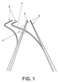
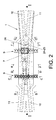
- the tram movable point turnout structure is defined by a support cradle 1 fastened in correspondence with the turnout interruption 2 of two rails 3 and 4 belonging to two different tracks 5 and 6, said cradle having a central space 7 housing a movable point 8 independent and linked to the support cradle 1 by means of a pair of transversal guides 9.
- the movable point 8 can take two end positions with transverse displacement corresponding to one of the two rails 3 or 4 that intersect depending on the selected track 5 or 6.
- the support cradle 1 has two pairs of end rail sections 10 and 11 that are a continuation of the two interrupted rails 3 and 4 which intersect from the two different tracks 5 and 6, so that such end rail sections 10-11 of the support cradle 1 are interrupted in a central area (central space 7) where the movable point 8 with transverse displacement is located.
- the movable point 8 has two side rail rolling portions 12 that converge towards the narrowest end of said movable point 8 such that depending on the end position of said movable point 8, the railway or tramway wheel 13 will rest on one or another side rolling portion 13 which will be a continuation of the respective pair of end rail sections 10 or 11 of the support cradle 1.
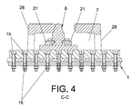
- Each transversal guide 9 comprises a guide-rail 14 immobilised by means of screws 15 and nuts 16, on which a car 17 is attached by means of a guidance system that includes rollers 18, elastic scrapers 19 and protective caps 20, attaching the movable point 8 to said the movable point 8 to said cars.
- the narrowest part of the movable point 8 has on its upper surface of a smooth end ramp 22 descending outwards that facilitates the rolling of the respective wheel 13 of the railway or tramway when contacting with that specific part.
- the widest end of the movable point 8 has a characteristic recess 23 including two planes 24 complemented with two other planes 25 of the support cradle 1 where the movable point 8 stops in its usage end positions.
- the movable point 8 has two side recesses 26 encasing the cars 17 of the transversal guides 9.
- the support cradle 1 has a characteristic robust structure comprising a horizontal base 27 from the central part from which surrounding side walls 28 with opposite end bracings delimiting the central space 7 where the movable point 8 and also the two transversal guides 9 are housed, extend upward.
- Said surrounding side walls 28 extend by their ends in partitions 29 finished at the top by centred bridges 30 and the pairs of end rail sections 10-11.
- the support cradle 1 includes a center rib 31 which includes the planes 25 where the planes 24 of the movable point stop when it is located in one of its stable, end positions, also including longitudinal wings 32 which are an extension of the sides of the horizontal base 27.
Landscapes
- Engineering & Computer Science (AREA)
- General Chemical & Material Sciences (AREA)
- Manufacturing & Machinery (AREA)
- Sustainable Development (AREA)
- Sustainable Energy (AREA)
- Chemical & Material Sciences (AREA)
- Chemical Kinetics & Catalysis (AREA)
- Electrochemistry (AREA)
- Life Sciences & Earth Sciences (AREA)
- Civil Engineering (AREA)
- Mechanical Engineering (AREA)
- Architecture (AREA)
- Structural Engineering (AREA)
- Train Traffic Observation, Control, And Security (AREA)
- Toys (AREA)
- Feeding Of Articles To Conveyors (AREA)
- Bearings For Parts Moving Linearly (AREA)
- De-Stacking Of Articles (AREA)
- Railway Tracks (AREA)
Abstract
Description
- As expressed in the title of this specification the present invention relates to a tram movable point turnout structure that improves the currently existing turnouts, facilitating the handling, as well as the replacement operations of worn parts and making it possible to completely eliminate the handling noise and also the bending stresses to which the movable points of the conventional turnouts are subjected.
- The turnout is a track apparatus that allows the separation of a rail track into two or more tracks, the axes which tangentially contact with that of the first one or at a very small angle with it.
- The simplest case of a turnout is the one called simple, or with two tracks that gives way to the circulation that take it to one track or the other. The main one receives the name of direct track and the other the diverging track.
- The separation and the turnout of the rolling of both tracks is produced by using the following elements: the turnout and the turnout, which along with the joining rails between them, form the three main parts of the apparatus these being the turnout, the joining or intermediate rails and the turnout itself.
- Thus, the turnout is formed by two tongue-stock rail (half-turnout) assemblies, allowing the splitting of the rolling threads.
- The joining intermediate rails connect said turnout with the turnout.
- The turnout itself, which is materialized in the intersection of the right lane (left) of the direct track with the left lane (right) of the diverging track.
- The turnout is the element of the turnout where there is the superposition of the travelled roads. The most common one consists of common turnout, check rails and rails. The turnout of common turnouts is the joining of two rails that intersect with each other. To allow the passage of the flange of the wheels a discontinuity is introduced in both rails, which empty space is called a gap. The extension that the rails have to allow the holding of the wheel rolling on the exterior end of the rim when the flange goes through the gap is called wing rails.
- The guard rails are intended to ensure the rail axis guiding when one of its wheels crosses the gap, avoiding the derailment of the vehicle and the deterioration of the common turnout. During the transit of the axles of the vehicles through the turnout, the collision of the wheels on common turnout areas may occur.
- These collisions reduce the useful life of both the turnout itself and the movable material circulating on it causing noise and violent movements affecting the comfort of the passengers.
- The shocks have two important consequences:
- they produce noises that bother the neighbours since these are apparatus installed in cities.
- they produce knocking that bothers the passengers of the tramway and they also produce wear on the common turnout itself and the wheels of the tramway.
- To ensure the safe passage of the vehicles through the turnout (without noises or knocking), it is necessary to eliminate the gap.
- Moving elements are inserted to suppress the gap removing it, keeping the corresponding common crossing wing rail. In this way, the check rails are unnecessary.
- Presently to eliminate the gap, there are essentially two typologies:
- the turnout with movable point common turnout.
- the turnout with movable wing rails.
- The flexible movable point turnout with common turnout as its name suggests, is a procedure to remove the gap in this type of common turnouts by bending the point of the common turnout, attaching one of its sides to the corresponding wing rail. In this way the gap disappears.
- The central block of the flexible movable common turnout consists of a forged, single piece, manufactured from standardised steel.
- This mechanism has the following drawbacks:
- A lot of handling effort is needed to move it because the point acts like a built-in beam.
- Difficulty when having to replace the tip when it wears out, since it is recessed and all the elements holding it have to be released and reassembled.
- Noise when carrying out the change although the noise when there is passing traffic is eliminated, the point, being recessed, when it is split and is free to move, does so producing the strong shake.
- It requires anti-lift since it is a long piece, a mechanism that prevents it from lifting is needed, especially if the trams are equipped with electromagnetic brakes.
- The turnout with movable wing rails makes it possible to totally remove the gap totally removing the gap keeping the point of the common turnout fastened and moving the corresponding wing rail.
- This mechanism has two major drawbacks:
- The development of an actuation and locking device of the wing rails that is sufficiently safe and reliable.
- The side guiding forces of the vehicles push the movable wing rail attached to one of the faces of the point of the fastened common turnout, trying to detach therefrom which would cause the derailment of the vehicle in the event it occurs.
- For the purpose of achieving the objectives and avoiding the drawbacks mentioned in the preceding paragraphs, the invention proposes to a movable tram turnout structure that has a characteristic structure that facilitates the handling and also the operations of replacement of worn parts, making it possible to totally eliminate the handling noise.
- The turnout structure is characterised in that it comprises a support cradle located in a gap corresponding to an empty space which interrupts the continuity of two rails turnout from two different tracks, so that said support cradle comprises a central space where a movable point is attached by using a transverse guidance system allowing said movable point to be moved without bending stress on the same. Hence, depending on the two end positions that the movable point can take in combination with the structure of the support cradle comprising of a fastened element, one or another lane of the two tracks intersecting is selected to direct the corresponding wheel of the railway or tramway by the track selected in simultaneous combination with the movement of blades.
- Therefore, the support cradle has two pairs of end rail sections that are a continuation of two interrupted rails that cross from the two different tracks so that such end rail sections of the support cradle are interrupted in a central area (central space) where the movable point with transverse displacement is located.
- The movable point has two side rolling rail portions that converge towards the narrowest end of said movable point, so that depending on the end position on said movable point, the wheel of the railway or tramway will rest on one or the other side rolling portion that will be a continuation of the respective pair of end rail sections of the support cradle.
- Other characteristics and advantages of the turnout structure of the invention are the following:
- The point is completely displaced, since it is not recessed like it is conventionally done.
- The fastening guiding of the movable point is through the use of sliding runners, screwed to the common turnout giving rise to the high-precision handling assembly. These guides are commonly used for guiding heads and tables in machine-tools.
- Total elimination of the handling noise, both in the direct track and the diverging track.
- The part of the turnout called support cradle is a hollow manganese steel casting that allows the insertion of the movable point and the fastening of its guidance elements.
- The support cradle has stops that make the movable point rigid opposite said support cradle when the tramway passes over the same.
- If it were necessary to replace the movable point, it only has to be released from the cars and then change it, without the need to remove the entire apparatus.
- The narrowest part of the movable point is fastened by two anti-lift flanges to prevent said area from rising.
- It is not necessary to make a check rail, since the width of track is maintained during the entire passage of the convoy by the entire turnout.
- Smaller than those of the flexible point.
- The actuation and locking system of the movable point is generally very similar to that used in the turnout.
- Next, in order to facilitate a better understanding of this specification and forming an integral part of the same, figures wherein with illustrative character and without limitation the object of the invention has been represented, are attached hereto.
-
-
Figure 1 shows a schematic view of the splitting of a railway track into two tracks including a turnout and a tram movable point turnout structure which is the object of the invention. The aforementioned turnout structure of the invention basically comprises a support cradle, a movable point with transverse displacement located in a central space of the support cradle, facilitating said displacement by a transverse guidance system. -
Figure 2 shows a plant view of the turnout structure. -
Figure 3 It shows an elevational view of the turnout structure according to the section I-I of the previous figure. -
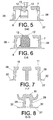
Figures 4 to 9 show different cross- sectional views of the turnout structure. -
Figures 10 and 11 show profile views of the turnout structure of the invention. -
Figure 12 shows a plant view of the movable point. -
Figure 13 shows an elevational view of the movable point. -
Figure 14 shows a sectional view according to a H-H cross-section of the movable point. -
Figure 15 shows a perspective view of the guidance of the movable point. - Considering the numbering adopted in the figures, the tram movable point turnout structure is defined by a
support cradle 1 fastened in correspondence with theturnout interruption 2 of tworails different tracks central space 7 housing amovable point 8 independent and linked to thesupport cradle 1 by means of a pair of transversal guides 9. - The
movable point 8 can take two end positions with transverse displacement corresponding to one of the tworails track - On the other hand, the
support cradle 1 has two pairs ofend rail sections rails different tracks support cradle 1 are interrupted in a central area (central space 7) where themovable point 8 with transverse displacement is located. - The
movable point 8 has two siderail rolling portions 12 that converge towards the narrowest end of saidmovable point 8 such that depending on the end position of saidmovable point 8, the railway ortramway wheel 13 will rest on one or anotherside rolling portion 13 which will be a continuation of the respective pair ofend rail sections support cradle 1. - Each
transversal guide 9 comprises a guide-rail 14 immobilised by means ofscrews 15 andnuts 16, on which acar 17 is attached by means of a guidance system that includesrollers 18,elastic scrapers 19 andprotective caps 20, attaching themovable point 8 to said themovable point 8 to said cars. - In addition, it should be noted that the narrowest part of the
movable point 8 has on its upper surface of asmooth end ramp 22 descending outwards that facilitates the rolling of therespective wheel 13 of the railway or tramway when contacting with that specific part. - Instead, the widest end of the
movable point 8 has acharacteristic recess 23 including twoplanes 24 complemented with two other planes 25 of thesupport cradle 1 where themovable point 8 stops in its usage end positions. - The
movable point 8 has twoside recesses 26 encasing thecars 17 of the transversal guides 9. - The
support cradle 1 has a characteristic robust structure comprising ahorizontal base 27 from the central part from which surroundingside walls 28 with opposite end bracings delimiting thecentral space 7 where themovable point 8 and also the twotransversal guides 9 are housed, extend upward. - Said surrounding
side walls 28 extend by their ends inpartitions 29 finished at the top bycentred bridges 30 and the pairs of end rail sections 10-11. - In turn, the
support cradle 1 includes a center rib 31 which includes the planes 25 where theplanes 24 of the movable point stop when it is located in one of its stable, end positions, also includinglongitudinal wings 32 which are an extension of the sides of thehorizontal base 27.
Claims (8)
- Movable point tram turnout structure, which being located in an interrupted space of two rails intersecting belonging to two different tracks, is characterised in that it comprises:- an immobilised support cradle (1) having a central space (7) and end rail sections (10-11) converging towards that central space (8) and aligned with the rails (3-4) of the turnout;- a movable point (8) located in the central space (7), which at the same time is transversally movable, and it can be placed stably on two end side positions to be aligned by the side rolling portions thereof (12) with one of the end rail sections (10-11);- transversal guides (9) located in the central space (7), by means of which the movable point (8) moves toward its end side positions.
- Movable point tram turnout structure, according to claim 1, characterised in that the transversal guides (9) comprise immobilised guide-rails (14), on which transversally movable cars (17) are attached, to which the movable point (8) is fastened.
- Movable point tram turnout structure, according to claim 2, characterised in that the transversal guides (9) include rollers (18), elastic scrapers (19) and protective caps (20).
- Movable point ram turnout, according to any one of the preceding claims, characterised in that it includes means to limit and stabilize the two end side positions of the movable point (8), said means consisting of a pair of planes (25) that are part of a midrib (31) of the support cradle (1), and other complementary planes (24) established in a recess (23), located in the widest end of the movable point (8).
- Movable point tram turnout, according to any one of the preceding claims, characterised in that the narrowest part of the movable point (8) has of a slight end ramp (22) descending downward on its upper surface descending outward.
- Movable point tram movable point turnout structure, according to any one of claims 2 to 5, characterised in that the narrowest and sharpest part of the movable point (8) is fastened by two side flanges (21) fastened to the respective movable car (17).
- Movable point tram turnout, according to any one of claims 2 to 6, characterised in that the movable point (8) has side recesses (26) encasing the cars (17) of the transversal guides (9).
- Movable point ram turnout, according to any one of the preceding claims, characterised in that the support cradle (1) comprises a horizontal base (27) from which surrounding side walls (28) with opposite bracing delimiting the central space (7) which protrude from the central part of which extend upwards, said surrounding side walls (28) extending by their end in partitions (29) finished at the top by centered bridges (30) and the pairs of end rails (10-11), while the support cradle (1) further includes the midrib (31) which includes the stop planes (25) of the movable point (8) and also longitudinal wings (32) which are an extension of the sides of the horizontal base (27) of the support cradle (1).
Applications Claiming Priority (2)
| Application Number | Priority Date | Filing Date | Title |
|---|---|---|---|
| ES201030084A ES2364827B1 (en) | 2010-01-25 | 2010-01-25 | PUNTA MOBILE TRANVIARY CROSSING STRUCTURE |
| PCT/ES2010/070349 WO2011089285A1 (en) | 2010-01-25 | 2010-05-25 | Tram crossing structure with movable point |
Publications (3)
| Publication Number | Publication Date |
|---|---|
| EP2530201A1 true EP2530201A1 (en) | 2012-12-05 |
| EP2530201A4 EP2530201A4 (en) | 2015-04-01 |
| EP2530201B1 EP2530201B1 (en) | 2017-07-05 |
Family
ID=43477909
Family Applications (1)
| Application Number | Title | Priority Date | Filing Date |
|---|---|---|---|
| EP10843781.5A Not-in-force EP2530201B1 (en) | 2010-01-25 | 2010-05-25 | Tram crossing structure with movable point |
Country Status (6)
| Country | Link |
|---|---|
| EP (1) | EP2530201B1 (en) |
| AR (1) | AR076614A1 (en) |
| BR (1) | BR112012018495A2 (en) |
| ES (2) | ES2364827B1 (en) |
| UY (1) | UY32677A (en) |
| WO (1) | WO2011089285A1 (en) |
Families Citing this family (2)
| Publication number | Priority date | Publication date | Assignee | Title |
|---|---|---|---|---|
| CN105064142B (en) * | 2015-07-16 | 2018-07-20 | 徐文 | A kind of rail junction track switch of multi-direction intercommunication |
| KR102367926B1 (en) * | 2020-04-27 | 2022-02-25 | 유일수 | fixing jig for preventing cracks of locking device of point machime |
Family Cites Families (19)
| Publication number | Priority date | Publication date | Assignee | Title |
|---|---|---|---|---|
| US402830A (en) * | 1889-05-07 | Sliding eailroad fkoa | ||
| GB190405017A (en) * | 1904-02-29 | 1904-12-08 | Almond A Kimball | Improvements in Railways Frogs or Crossings |
| US837807A (en) * | 1906-04-21 | 1906-12-04 | Fred J Bellmer | Railway-frog. |
| US1634638A (en) * | 1926-08-11 | 1927-07-05 | Anthony L Vissat | Railway frog |
| US2449757A (en) * | 1944-11-27 | 1948-09-21 | Anthony L Vissat | Transversely sliding railway frog |
| GB1543800A (en) * | 1976-12-31 | 1979-04-04 | Japan Airlines Co | Track switching device for two rail type tracks |
| JPS5838801U (en) * | 1981-09-04 | 1983-03-14 | 清田軌道工業株式会社 | track turnout |
| ES2137807B1 (en) * | 1996-04-29 | 2000-08-16 | Jez Sistemas Ferroviarios S L | ACUTE MOBILE TIP CROSSING FOR RAILWAY. |
| CN2361662Y (en) * | 1999-01-11 | 2000-02-02 | 王子怀 | Movable center points |
| GB0126604D0 (en) * | 2001-11-06 | 2002-01-02 | Adelan Ltd | Fuel cell element |
| US8658327B2 (en) * | 2002-02-20 | 2014-02-25 | Acumentrics Corporation | Fuel cell stacking and sealing |
| JP4018921B2 (en) * | 2002-03-27 | 2007-12-05 | 京セラ株式会社 | Fuel cell |
| DE10215060A1 (en) * | 2002-04-05 | 2003-10-23 | Thyssenkrupp Weichenbau Gmbh | Crossing or switch |
| DE10356719A1 (en) * | 2003-12-02 | 2005-06-30 | Bwg Gmbh & Co. Kg | heart |
| ES2265237B1 (en) * | 2004-09-08 | 2007-12-16 | Felguera Melt, S.A. | DEVICE FOR THE DECREASE OF MANEUVER EFFORTS IN THE PUNTA MOBILE RAILWAY CROSSINGS. |
| US7785747B2 (en) * | 2005-04-11 | 2010-08-31 | Worldwide Energy, Inc. Of Delaware | Stack configurations for tubular solid oxide fuel cells |
| FR2892237B1 (en) * | 2005-10-19 | 2007-11-30 | Commissariat Energie Atomique | FUEL CELL TUBULAR MODULE AND ITS SEALING DEVICE |
| JP2007220632A (en) * | 2006-02-20 | 2007-08-30 | Toyota Motor Corp | Tube type fuel cell module |
| KR100681007B1 (en) * | 2006-04-04 | 2007-02-09 | 한국에너지기술연구원 | Sealant and sealing method for tubular anode support solid oxide fuel cell |
-
2010
- 2010-01-25 ES ES201030084A patent/ES2364827B1/en not_active Expired - Fee Related
- 2010-05-25 WO PCT/ES2010/070349 patent/WO2011089285A1/en not_active Ceased
- 2010-05-25 EP EP10843781.5A patent/EP2530201B1/en not_active Not-in-force
- 2010-05-25 BR BR112012018495A patent/BR112012018495A2/en not_active IP Right Cessation
- 2010-05-25 ES ES10843781.5T patent/ES2642402T3/en active Active
- 2010-05-28 AR ARP100101861A patent/AR076614A1/en unknown
- 2010-05-28 UY UY0001032677A patent/UY32677A/en unknown
Also Published As
| Publication number | Publication date |
|---|---|
| ES2364827B1 (en) | 2012-08-03 |
| UY32677A (en) | 2010-12-31 |
| AR076614A1 (en) | 2011-06-22 |
| BR112012018495A2 (en) | 2016-04-12 |
| EP2530201A4 (en) | 2015-04-01 |
| WO2011089285A1 (en) | 2011-07-28 |
| EP2530201B1 (en) | 2017-07-05 |
| ES2364827A1 (en) | 2011-09-15 |
| ES2642402T3 (en) | 2017-11-16 |
Similar Documents
| Publication | Publication Date | Title |
|---|---|---|
| EP1995145B1 (en) | Carriage lateral movement-limiting system | |
| CN110983874B (en) | A wheel-rail structure suspension type PRT elastic switch-track switch structure and switch method | |
| EP2557228A1 (en) | Interlocking device for a moveable point frog | |
| DE2304958A1 (en) | CONVEYOR DEVICE WITH WHEELS RUNNING IN THE HALL AND WITH FORCED GUIDANCE | |
| US10577751B2 (en) | Operating and locking mechanism for diamond crossings of central rail-guided vehicles | |
| EP2530201B1 (en) | Tram crossing structure with movable point | |
| FI89147C (en) | OEVERGAONGSBRO FOER EN OEVERGAONGSANORDNINGAR | |
| SU1004181A1 (en) | Variable-track wheel pair | |
| US20260078550A1 (en) | Passive switch for a rail-bound traffic system, chassis for a rail-bound traffic system and rail-bound traffic system | |
| CA2867870C (en) | Device to maintain a trajectory of a guided vehicle in the event of derailment and/or failure of guidance | |
| US3774543A (en) | Passenger vehicle static switching apparatus | |
| US3697747A (en) | Frog | |
| CN213013713U (en) | Translation type turnout | |
| US3910534A (en) | Great-length frogs for very high speed traffic railway tracks | |
| EP2964831B1 (en) | Rail junction assembly | |
| CN112391885B (en) | A turnout structure and turnout diversion method for suspended monorail | |
| US20070007394A1 (en) | System, method, and apparatus for railroad turnout and derail lift frog | |
| Bugarín et al. | Geometry of high-speed turnouts | |
| US20160144874A1 (en) | Passive Switch For A Railway Track | |
| US10781558B2 (en) | Operating and locking mechanism for turnouts of central rail-guided vehicles | |
| KR101744064B1 (en) | a mounting struture of LRT | |
| KR20200030150A (en) | Rail installation structure for dual gauge railway | |
| JPH06240608A (en) | Fixed equipment for changing railway gauge | |
| EP2240642B1 (en) | Swing nose crossing | |
| EP2374684B1 (en) | Devices for moving the buffers of the coaches of railway vehicles with bogies in curves and railway vehicle coach with bogies |
Legal Events
| Date | Code | Title | Description |
|---|---|---|---|
| PUAI | Public reference made under article 153(3) epc to a published international application that has entered the european phase |
Free format text: ORIGINAL CODE: 0009012 |
|
| 17P | Request for examination filed |
Effective date: 20120731 |
|
| AK | Designated contracting states |
Kind code of ref document: A1 Designated state(s): AL AT BE BG CH CY CZ DE DK EE ES FI FR GB GR HR HU IE IS IT LI LT LU LV MC MK MT NL NO PL PT RO SE SI SK SM TR |
|
| DAX | Request for extension of the european patent (deleted) | ||
| A4 | Supplementary search report drawn up and despatched |
Effective date: 20150226 |
|
| RIC1 | Information provided on ipc code assigned before grant |
Ipc: E01B 7/14 20060101AFI20150220BHEP |
|
| GRAP | Despatch of communication of intention to grant a patent |
Free format text: ORIGINAL CODE: EPIDOSNIGR1 |
|
| INTG | Intention to grant announced |
Effective date: 20170127 |
|
| GRAS | Grant fee paid |
Free format text: ORIGINAL CODE: EPIDOSNIGR3 |
|
| GRAA | (expected) grant |
Free format text: ORIGINAL CODE: 0009210 |
|
| AK | Designated contracting states |
Kind code of ref document: B1 Designated state(s): AL AT BE BG CH CY CZ DE DK EE ES FI FR GB GR HR HU IE IS IT LI LT LU LV MC MK MT NL NO PL PT RO SE SI SK SM TR |
|
| REG | Reference to a national code |
Ref country code: GB Ref legal event code: FG4D |
|
| REG | Reference to a national code |
Ref country code: CH Ref legal event code: EP |
|
| REG | Reference to a national code |
Ref country code: AT Ref legal event code: REF Ref document number: 906698 Country of ref document: AT Kind code of ref document: T Effective date: 20170715 |
|
| REG | Reference to a national code |
Ref country code: IE Ref legal event code: FG4D |
|
| REG | Reference to a national code |
Ref country code: DE Ref legal event code: R096 Ref document number: 602010043500 Country of ref document: DE |
|
| REG | Reference to a national code |
Ref country code: NL Ref legal event code: FP |
|
| REG | Reference to a national code |
Ref country code: AT Ref legal event code: MK05 Ref document number: 906698 Country of ref document: AT Kind code of ref document: T Effective date: 20170705 |
|
| REG | Reference to a national code |
Ref country code: ES Ref legal event code: FG2A Ref document number: 2642402 Country of ref document: ES Kind code of ref document: T3 Effective date: 20171116 |
|
| REG | Reference to a national code |
Ref country code: LT Ref legal event code: MG4D |
|
| PG25 | Lapsed in a contracting state [announced via postgrant information from national office to epo] |
Ref country code: NO Free format text: LAPSE BECAUSE OF FAILURE TO SUBMIT A TRANSLATION OF THE DESCRIPTION OR TO PAY THE FEE WITHIN THE PRESCRIBED TIME-LIMIT Effective date: 20171005 Ref country code: SE Free format text: LAPSE BECAUSE OF FAILURE TO SUBMIT A TRANSLATION OF THE DESCRIPTION OR TO PAY THE FEE WITHIN THE PRESCRIBED TIME-LIMIT Effective date: 20170705 Ref country code: AT Free format text: LAPSE BECAUSE OF FAILURE TO SUBMIT A TRANSLATION OF THE DESCRIPTION OR TO PAY THE FEE WITHIN THE PRESCRIBED TIME-LIMIT Effective date: 20170705 Ref country code: HR Free format text: LAPSE BECAUSE OF FAILURE TO SUBMIT A TRANSLATION OF THE DESCRIPTION OR TO PAY THE FEE WITHIN THE PRESCRIBED TIME-LIMIT Effective date: 20170705 Ref country code: LT Free format text: LAPSE BECAUSE OF FAILURE TO SUBMIT A TRANSLATION OF THE DESCRIPTION OR TO PAY THE FEE WITHIN THE PRESCRIBED TIME-LIMIT Effective date: 20170705 Ref country code: FI Free format text: LAPSE BECAUSE OF FAILURE TO SUBMIT A TRANSLATION OF THE DESCRIPTION OR TO PAY THE FEE WITHIN THE PRESCRIBED TIME-LIMIT Effective date: 20170705 |
|
| PG25 | Lapsed in a contracting state [announced via postgrant information from national office to epo] |
Ref country code: PL Free format text: LAPSE BECAUSE OF FAILURE TO SUBMIT A TRANSLATION OF THE DESCRIPTION OR TO PAY THE FEE WITHIN THE PRESCRIBED TIME-LIMIT Effective date: 20170705 Ref country code: IS Free format text: LAPSE BECAUSE OF FAILURE TO SUBMIT A TRANSLATION OF THE DESCRIPTION OR TO PAY THE FEE WITHIN THE PRESCRIBED TIME-LIMIT Effective date: 20171105 Ref country code: BG Free format text: LAPSE BECAUSE OF FAILURE TO SUBMIT A TRANSLATION OF THE DESCRIPTION OR TO PAY THE FEE WITHIN THE PRESCRIBED TIME-LIMIT Effective date: 20171005 Ref country code: LV Free format text: LAPSE BECAUSE OF FAILURE TO SUBMIT A TRANSLATION OF THE DESCRIPTION OR TO PAY THE FEE WITHIN THE PRESCRIBED TIME-LIMIT Effective date: 20170705 Ref country code: GR Free format text: LAPSE BECAUSE OF FAILURE TO SUBMIT A TRANSLATION OF THE DESCRIPTION OR TO PAY THE FEE WITHIN THE PRESCRIBED TIME-LIMIT Effective date: 20171006 |
|
| REG | Reference to a national code |
Ref country code: DE Ref legal event code: R097 Ref document number: 602010043500 Country of ref document: DE |
|
| PG25 | Lapsed in a contracting state [announced via postgrant information from national office to epo] |
Ref country code: CZ Free format text: LAPSE BECAUSE OF FAILURE TO SUBMIT A TRANSLATION OF THE DESCRIPTION OR TO PAY THE FEE WITHIN THE PRESCRIBED TIME-LIMIT Effective date: 20170705 Ref country code: DK Free format text: LAPSE BECAUSE OF FAILURE TO SUBMIT A TRANSLATION OF THE DESCRIPTION OR TO PAY THE FEE WITHIN THE PRESCRIBED TIME-LIMIT Effective date: 20170705 Ref country code: RO Free format text: LAPSE BECAUSE OF FAILURE TO SUBMIT A TRANSLATION OF THE DESCRIPTION OR TO PAY THE FEE WITHIN THE PRESCRIBED TIME-LIMIT Effective date: 20170705 |
|
| PLBE | No opposition filed within time limit |
Free format text: ORIGINAL CODE: 0009261 |
|
| STAA | Information on the status of an ep patent application or granted ep patent |
Free format text: STATUS: NO OPPOSITION FILED WITHIN TIME LIMIT |
|
| PG25 | Lapsed in a contracting state [announced via postgrant information from national office to epo] |
Ref country code: SM Free format text: LAPSE BECAUSE OF FAILURE TO SUBMIT A TRANSLATION OF THE DESCRIPTION OR TO PAY THE FEE WITHIN THE PRESCRIBED TIME-LIMIT Effective date: 20170705 Ref country code: SK Free format text: LAPSE BECAUSE OF FAILURE TO SUBMIT A TRANSLATION OF THE DESCRIPTION OR TO PAY THE FEE WITHIN THE PRESCRIBED TIME-LIMIT Effective date: 20170705 Ref country code: EE Free format text: LAPSE BECAUSE OF FAILURE TO SUBMIT A TRANSLATION OF THE DESCRIPTION OR TO PAY THE FEE WITHIN THE PRESCRIBED TIME-LIMIT Effective date: 20170705 |
|
| REG | Reference to a national code |
Ref country code: FR Ref legal event code: PLFP Year of fee payment: 9 |
|
| 26N | No opposition filed |
Effective date: 20180406 |
|
| PGFP | Annual fee paid to national office [announced via postgrant information from national office to epo] |
Ref country code: LU Payment date: 20180509 Year of fee payment: 9 |
|
| PG25 | Lapsed in a contracting state [announced via postgrant information from national office to epo] |
Ref country code: SI Free format text: LAPSE BECAUSE OF FAILURE TO SUBMIT A TRANSLATION OF THE DESCRIPTION OR TO PAY THE FEE WITHIN THE PRESCRIBED TIME-LIMIT Effective date: 20170705 |
|
| PGFP | Annual fee paid to national office [announced via postgrant information from national office to epo] |
Ref country code: NL Payment date: 20180508 Year of fee payment: 9 Ref country code: FR Payment date: 20180601 Year of fee payment: 9 Ref country code: IT Payment date: 20180509 Year of fee payment: 9 Ref country code: BE Payment date: 20180531 Year of fee payment: 9 |
|
| REG | Reference to a national code |
Ref country code: DE Ref legal event code: R119 Ref document number: 602010043500 Country of ref document: DE |
|
| REG | Reference to a national code |
Ref country code: CH Ref legal event code: PL |
|
| GBPC | Gb: european patent ceased through non-payment of renewal fee |
Effective date: 20180525 |
|
| PG25 | Lapsed in a contracting state [announced via postgrant information from national office to epo] |
Ref country code: MC Free format text: LAPSE BECAUSE OF FAILURE TO SUBMIT A TRANSLATION OF THE DESCRIPTION OR TO PAY THE FEE WITHIN THE PRESCRIBED TIME-LIMIT Effective date: 20170705 |
|
| REG | Reference to a national code |
Ref country code: IE Ref legal event code: MM4A |
|
| PG25 | Lapsed in a contracting state [announced via postgrant information from national office to epo] |
Ref country code: CH Free format text: LAPSE BECAUSE OF NON-PAYMENT OF DUE FEES Effective date: 20180531 Ref country code: LI Free format text: LAPSE BECAUSE OF NON-PAYMENT OF DUE FEES Effective date: 20180531 |
|
| PG25 | Lapsed in a contracting state [announced via postgrant information from national office to epo] |
Ref country code: IE Free format text: LAPSE BECAUSE OF NON-PAYMENT OF DUE FEES Effective date: 20180525 Ref country code: DE Free format text: LAPSE BECAUSE OF NON-PAYMENT OF DUE FEES Effective date: 20181201 Ref country code: GB Free format text: LAPSE BECAUSE OF NON-PAYMENT OF DUE FEES Effective date: 20180525 |
|
| REG | Reference to a national code |
Ref country code: NL Ref legal event code: MM Effective date: 20190601 |
|
| PG25 | Lapsed in a contracting state [announced via postgrant information from national office to epo] |
Ref country code: MT Free format text: LAPSE BECAUSE OF NON-PAYMENT OF DUE FEES Effective date: 20180525 |
|
| REG | Reference to a national code |
Ref country code: BE Ref legal event code: MM Effective date: 20190531 |
|
| PG25 | Lapsed in a contracting state [announced via postgrant information from national office to epo] |
Ref country code: LU Free format text: LAPSE BECAUSE OF NON-PAYMENT OF DUE FEES Effective date: 20190525 |
|
| PG25 | Lapsed in a contracting state [announced via postgrant information from national office to epo] |
Ref country code: TR Free format text: LAPSE BECAUSE OF FAILURE TO SUBMIT A TRANSLATION OF THE DESCRIPTION OR TO PAY THE FEE WITHIN THE PRESCRIBED TIME-LIMIT Effective date: 20170705 |
|
| PG25 | Lapsed in a contracting state [announced via postgrant information from national office to epo] |
Ref country code: NL Free format text: LAPSE BECAUSE OF NON-PAYMENT OF DUE FEES Effective date: 20190601 Ref country code: IT Free format text: LAPSE BECAUSE OF NON-PAYMENT OF DUE FEES Effective date: 20190525 |
|
| PG25 | Lapsed in a contracting state [announced via postgrant information from national office to epo] |
Ref country code: HU Free format text: LAPSE BECAUSE OF FAILURE TO SUBMIT A TRANSLATION OF THE DESCRIPTION OR TO PAY THE FEE WITHIN THE PRESCRIBED TIME-LIMIT; INVALID AB INITIO Effective date: 20100525 Ref country code: BE Free format text: LAPSE BECAUSE OF NON-PAYMENT OF DUE FEES Effective date: 20190531 Ref country code: PT Free format text: LAPSE BECAUSE OF FAILURE TO SUBMIT A TRANSLATION OF THE DESCRIPTION OR TO PAY THE FEE WITHIN THE PRESCRIBED TIME-LIMIT Effective date: 20170705 |
|
| PG25 | Lapsed in a contracting state [announced via postgrant information from national office to epo] |
Ref country code: FR Free format text: LAPSE BECAUSE OF NON-PAYMENT OF DUE FEES Effective date: 20190531 Ref country code: CY Free format text: LAPSE BECAUSE OF FAILURE TO SUBMIT A TRANSLATION OF THE DESCRIPTION OR TO PAY THE FEE WITHIN THE PRESCRIBED TIME-LIMIT Effective date: 20170705 Ref country code: MK Free format text: LAPSE BECAUSE OF NON-PAYMENT OF DUE FEES Effective date: 20170705 |
|
| PG25 | Lapsed in a contracting state [announced via postgrant information from national office to epo] |
Ref country code: AL Free format text: LAPSE BECAUSE OF FAILURE TO SUBMIT A TRANSLATION OF THE DESCRIPTION OR TO PAY THE FEE WITHIN THE PRESCRIBED TIME-LIMIT Effective date: 20170705 |
|
| PGFP | Annual fee paid to national office [announced via postgrant information from national office to epo] |
Ref country code: ES Payment date: 20200601 Year of fee payment: 11 |
|
| REG | Reference to a national code |
Ref country code: ES Ref legal event code: FD2A Effective date: 20220804 |
|
| PG25 | Lapsed in a contracting state [announced via postgrant information from national office to epo] |
Ref country code: ES Free format text: LAPSE BECAUSE OF NON-PAYMENT OF DUE FEES Effective date: 20210526 |