EP2529982A1 - Seatbelt retractor and seatbelt device provided with same - Google Patents
Seatbelt retractor and seatbelt device provided with same Download PDFInfo
- Publication number
- EP2529982A1 EP2529982A1 EP10844555A EP10844555A EP2529982A1 EP 2529982 A1 EP2529982 A1 EP 2529982A1 EP 10844555 A EP10844555 A EP 10844555A EP 10844555 A EP10844555 A EP 10844555A EP 2529982 A1 EP2529982 A1 EP 2529982A1
- Authority
- EP
- European Patent Office
- Prior art keywords
- seatbelt
- spool
- rotation
- seatbelt retractor
- receiving
- Prior art date
- Legal status (The legal status is an assumption and is not a legal conclusion. Google has not performed a legal analysis and makes no representation as to the accuracy of the status listed.)
- Ceased
Links
- 238000001514 detection method Methods 0.000 abstract description 16
- 230000005540 biological transmission Effects 0.000 description 9
- 230000000694 effects Effects 0.000 description 5
- 238000009434 installation Methods 0.000 description 3
- 238000004804 winding Methods 0.000 description 1
Images




Classifications
-
- B—PERFORMING OPERATIONS; TRANSPORTING
- B60—VEHICLES IN GENERAL
- B60R—VEHICLES, VEHICLE FITTINGS, OR VEHICLE PARTS, NOT OTHERWISE PROVIDED FOR
- B60R22/00—Safety belts or body harnesses in vehicles
- B60R22/34—Belt retractors, e.g. reels
- B60R22/44—Belt retractors, e.g. reels with means for reducing belt tension during use under normal conditions
-
- B—PERFORMING OPERATIONS; TRANSPORTING
- B60—VEHICLES IN GENERAL
- B60R—VEHICLES, VEHICLE FITTINGS, OR VEHICLE PARTS, NOT OTHERWISE PROVIDED FOR
- B60R22/00—Safety belts or body harnesses in vehicles
- B60R22/34—Belt retractors, e.g. reels
- B60R22/46—Reels with means to tension the belt in an emergency by forced winding up
-
- B—PERFORMING OPERATIONS; TRANSPORTING
- B60—VEHICLES IN GENERAL
- B60R—VEHICLES, VEHICLE FITTINGS, OR VEHICLE PARTS, NOT OTHERWISE PROVIDED FOR
- B60R22/00—Safety belts or body harnesses in vehicles
- B60R22/34—Belt retractors, e.g. reels
- B60R22/44—Belt retractors, e.g. reels with means for reducing belt tension during use under normal conditions
- B60R2022/4473—Belt retractors, e.g. reels with means for reducing belt tension during use under normal conditions using an electric retraction device
-
- B—PERFORMING OPERATIONS; TRANSPORTING
- B60—VEHICLES IN GENERAL
- B60R—VEHICLES, VEHICLE FITTINGS, OR VEHICLE PARTS, NOT OTHERWISE PROVIDED FOR
- B60R22/00—Safety belts or body harnesses in vehicles
- B60R22/34—Belt retractors, e.g. reels
- B60R22/46—Reels with means to tension the belt in an emergency by forced winding up
- B60R2022/4666—Reels with means to tension the belt in an emergency by forced winding up characterised by electric actuators
-
- B—PERFORMING OPERATIONS; TRANSPORTING
- B60—VEHICLES IN GENERAL
- B60R—VEHICLES, VEHICLE FITTINGS, OR VEHICLE PARTS, NOT OTHERWISE PROVIDED FOR
- B60R22/00—Safety belts or body harnesses in vehicles
- B60R22/34—Belt retractors, e.g. reels
- B60R22/46—Reels with means to tension the belt in an emergency by forced winding up
- B60R2022/4685—Reels with means to tension the belt in an emergency by forced winding up with means to adjust or regulate the tensioning force in relation to external parameters
-
- B—PERFORMING OPERATIONS; TRANSPORTING
- B60—VEHICLES IN GENERAL
- B60R—VEHICLES, VEHICLE FITTINGS, OR VEHICLE PARTS, NOT OTHERWISE PROVIDED FOR
- B60R22/00—Safety belts or body harnesses in vehicles
- B60R22/48—Control systems, alarms, or interlock systems, for the correct application of the belt or harness
- B60R2022/4808—Sensing means arrangements therefor
- B60R2022/4825—Sensing means arrangements therefor for sensing amount of belt winded on retractor
Definitions
- the present invention relates to a technical field of a seatbelt retractor and a seatbelt apparatus including the same in which an electric motor serving as a drive means drives and controls rotation of a spool to retract and withdraw a seatbelt.
- the present invention relates to a technical field of a seatbelt retractor and a seatbelt apparatus including the same that include a rotation detecting member configured to detect the amount of rotation of a spool.
- a seatbelt apparatus mounted on a vehicle restrains an occupant with a seatbelt to prevent the occupant from moving forward from the seat in an emergency, such as a vehicle collision.
- a seatbelt apparatus includes a seatbelt retractor that retracts a seatbelt.
- the seatbelt In the seatbelt retractor, the seatbelt is retracted onto a spool when it is not in use, and is withdrawn and worn by an occupant when it is in use.
- a means for locking the seatbelt retractor is actuated to prevent the spool from rotating in the belt withdrawing direction, thereby preventing the seatbelt from being withdrawn.
- the seatbelt retains the occupant in an emergency.
- Various seatbelt apparatuses which include, as a seatbelt retractor, a motor retractor in which a spool for retracting a seatbelt is rotated by power of a motor.
- a controller drives and controls an electric motor, serving as a drive means, to control the belt retraction onto the spool and the belt withdrawal from the spool.
- a seatbelt retractor which includes a rotation sensor that detects the amount and direction of rotation of a spool.
- the rotation sensor includes magnets, a rotating disk supported by a rotating shaft of the spool so as to be rotatable integrally with the spool, and Hall elements (Hall ICs) configured to detect rotation of the rotating disk by detecting the magnets.
- the seatbelt retractor controls an electric motor on the basis of the amount of rotation of the spool detected by the rotation sensor (see, e.g., Patent Literature (PTL) 1).
- Fig. 5 illustrates a seatbelt apparatus described in PTL 1.
- Fig. 6 illustrates a partial cross section of a seatbelt retractor described in PTL 1.
- Fig. 7(a) illustrates annularly arranged magnets of a rotation sensor described in PTL 1.
- Fig. 7(b) is a partial view corresponding to part VIIB of Fig. 7(a).
- Fig. 7(c) is a cross-sectional view taken along line VIIC-VIIC of Fig. 7(b) .
- Fig. 8 illustrates how the rotation sensor detects rotation.
- reference numeral 1 denotes a seatbelt apparatus
- reference numeral 2 denotes a vehicle seat
- reference numeral 3 denotes a seatbelt retractor configured as a motor retractor
- reference numeral 4 denotes a seatbelt withdrawably retracted by the seatbelt retractor 3, the seatbelt having a belt anchor 4a at an end thereof to be secured to a vehicle floor or the vehicle seat 2
- reference numeral 5 denotes a guide anchor configured to guide the seatbelt 4 withdrawn from the seatbelt retractor 3 to a shoulder of an occupant
- reference numeral 6 denotes a tongue slidably supported by the seatbelt 4 guided by the guide anchor 5
- reference numeral 7 denotes a buckle secured to the vehicle floor or the vehicle seat and into which the tongue 6 is engageably and disengageably inserted and engaged
- reference numeral 8 denotes an electric motor serving as a drive means that rotates a spool 10 of the seatbelt retractor 3 to retract and withdraw the
- the rotating disk 18 and the magnets 21 also rotate in the seatbelt withdrawing direction.
- This allows the pair of Hall elements 20 to detect the N-pole magnets 21a and the S-pole magnets 21b and output the resulting detection signals to the controller 16.
- the Hall elements 20 detect the N-pole magnets 21a and the S-pole magnets 21b alternately, the current polarities of the detection signals from the Hall elements 20 switch from one to the other.
- the detection signals from the Hall elements 20 are out of phase by a predetermined amount.
- the controller 16 counts the number of times the current polarities of the detection signals from the Hall elements 20 have switched, and thereby detects the amount of rotation of the spool 10.
- the controller 16 determines whether the spool 10 is rotating in the seatbelt withdrawing or retracting direction. Then, on the basis of the amount and direction of rotation of the spool 10, the controller 16 controls drive of the electric motor 8 to control the belt tension of the seatbelt 4.
- the bracket 19 to which the pair of Hall elements 20 of the rotation sensor 15 is attached is secured to the right side wall 9b of the frame 9.
- the bushing 10b mounted on the rotating shaft 10a of the spool 10 passes through the bracket 19 so as to be rotatable relative to the bracket 19.
- the spool 10 has some play with respect to the frame 9. Therefore, when the spool 10 rattles, the bracket 19 functions as a bearing that supports the rotating shaft 10a and the bushing 10b.
- An object of the present invention is to provide a seatbelt retractor and a seatbelt apparatus including the same that can improve detection accuracy of a rotation detecting member, reduce a load applied to the rotation detecting member, and suppress an increase in size in the thrust direction.
- a seatbelt retractor includes at least a spool configured to retract a seatbelt, drive means for rotating the spool, and a rotation detecting member configured to detect the amount of rotation of the spool.
- the amount of rotation of the spool is controlled by driving and controlling the drive means on the basis of the amount of rotation of the spool detected by the rotation detecting member.
- the rotation detecting member is disposed eccentrically with respect to a rotating shaft of the spool in a radial direction of the rotating shaft.
- the rotation detecting member is disposed in a direction in which the rotating shaft is separated from the rotation detecting member by a load applied from the seatbelt to the spool in an emergency.
- the rotation detecting member includes a rotating disk that includes a predetermined number of magnets and a receiving member rotatable integrally with the predetermined number of magnets.
- the predetermined number of magnets include N-pole magnets and S-pole magnets alternately and annularly arranged concentrically with the rotating disk.
- the seatbelt retractor further includes a transmitting member configured to transmit rotation of the spool to the receiving member, the transmitting member being mounted on the spool so as to be rotatable integrally with the spool; and a magnet detecting member configured to detect a magnet located at a predetermined position, the magnet being any of the predetermined number of magnets.
- the seatbelt retractor according to the present invention further includes a speed increasing mechanism configured to increase a rotation speed of the transmitting member to transmit the rotation speed to the receiving member, and increase a rotation speed of the spool to rotate the magnets.
- the receiving member is a receiving gear and the transmitting member is a transmitting gear that engages with the receiving gear, and the speed increasing mechanism is composed of the receiving gear and the transmitting gear.
- the receiving member is a receiving pulley and the transmitting member is a transmitting pulley; and the speed increasing mechanism is composed of the receiving pulley, the transmitting pulley, and an endless belt wound around the receiving pulley and the transmitting pulley.
- a seatbelt apparatus includes at least a seatbelt retractor configured to retract a seatbelt, a tongue slidably supported by the seatbelt withdrawn from the seatbelt retractor, and a buckle with which the tongue is engageably and disengageably engaged.
- the seatbelt apparatus is configured to restrain an occupant with the seatbelt.
- the seatbelt retractor is any one of the seatbelt retractors according to the present invention described above.
- the rotation detecting member is disposed eccentrically with respect to the rotating shaft of the spool in a radial direction of the rotating shaft. Therefore, unlike the conventional example, the rotation detecting member does not function as a bearing for the spool. Thus, even if a large load is applied from the seatbelt to the spool in an emergency, it is possible to effectively suppress transmission of the large load to the rotation detecting member. As a result, the size of the rotation detecting member in the thrust direction (or in the axial direction of the spool) can be made smaller than that in the conventional example.
- the rotation detecting member is disposed in a direction in which the rotating shaft is separated from the rotation detecting member by a large load applied to the spool in an emergency, it is possible to more effectively suppress transmission of the large load to the rotation detecting member in an emergency.
- the size of the rotation detecting member in the thrust direction can be made smaller than that in the conventional example.
- the rotation detecting member is disposed eccentrically with respect to the rotating shaft of the spool in a radial direction of the rotating shaft, it is possible to more effectively suppress an increase in size of the seatbelt retractor in the thrust direction.
- the transmission of the large load to the rotation detecting member can be suppressed, it is possible to suppress influence of the large load on the rotation detecting member. It is thus possible to improve detection accuracy of the rotation detecting member. Additionally, if a large deceleration is exerted on the vehicle in an emergency, since an inertial force of the occupant applied to the seatbelt is directed substantially forward, the direction of the load is substantially constant. Therefore, it is possible to easily set the installation position of the rotation detecting member.
- the speed increasing mechanism that increases the speed of rotation of the spool at a predetermined speed-doubling rate to rotate the magnets is disposed between the rotation detecting member and the rotating shaft of the spool.
- the rotation speed of the magnets is larger than that of the spool, the circumferential length of each of the N-pole magnets and S-pole magnets can be set to be long.
- a reference angle to be detected by the rotation detecting member can be made larger than a reference angle to be detected by the conventional rotation sensor. It is thus possible to effectively reduce variation in detection of the rotation detecting member. Therefore, it is possible to more effectively improve detection accuracy of the rotation detecting member.
- the seatbelt apparatus which includes the seatbelt retractor of the present invention, it is possible to efficiently restrain an occupant with the seatbelt for a long period of time depending on how the vehicle runs, how the seatbelt apparatus is used, etc.
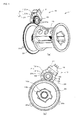
- Fig. 1(a) is a perspective view partially illustrating a first embodiment of a seatbelt retractor according to the present invention
- Fig. 1(b) is a right side view of Fig. 1(a)
- components identical to those in previous embodiments and those of the seatbelt retractor and the seatbelt apparatus described in PTL 1 are given the same reference numerals and their detailed description will be omitted.
- a seatbelt retractor 3 of the first embodiment includes a rotation sensor 15 serving as a rotation detecting member.
- the rotation sensor 15 is disposed eccentrically with respect to a rotating shaft 10a of a spool 10.
- the rotation sensor 15 includes a rotating disk 18 rotatably attached to a right side wall 9b of a frame, and a bracket 19 immovably attached to the right side wall 9b of the frame.
- the rotating disk 18 includes an annular magnet holding member 22 and annularly arranged magnets 21 rotatable integrally with the magnet holding member 22.
- the annularly arranged magnets 21 include N-pole magnets 21a and S-pole magnets 21b arranged alternately.
- the magnet holding member 22 is integral with a tubular transmitting gear 23 (corresponding to a receiving member) having external teeth 23a arranged concentrically with the magnet holding member 22.
- a transmitting gear 24 (corresponding to a transmitting member) is mounted through a bushing 10b on the rotating shaft 10a of the spool 10 so as to be concentric with and rotatable integrally with the rotating shaft 10a.
- the transmitting gear 24 has external teeth 24a, which engage with the external teeth 23a of the receiving gear 23.
- a pair of Hall elements (Hall ICs) 20 serving as a magnet detecting member is attached to the bracket 19 so as to face some of the magnets 21.
- the Hall elements 20 detect magnets 21 located at respective predetermined positions.
- the rotation sensor 15 is disposed in a radial direction of the transmitting gear 24 (or in a radial direction of the rotating shaft 10a). As illustrated in Fig. 2 , the external teeth 23a of the receiving gear 23 engage with the external teeth 24a of the transmitting gear 24 at a position in a direction in which the transmitting gear 24 (or the rotating shaft 10a) is moved away (or separated) from the receiving gear 23 (or the rotation sensor 15) by a large load F applied from the seatbelt 4 to the spool 10 in an emergency.
- a gear ratio between the external teeth 23a of the receiving gear 23 of the rotation sensor 15 and the external teeth 24a of the transmitting gear 24 is set such that the speed of rotation of the receiving gear 23 (or rotation of the magnets 21) is faster than that of rotation of the transmitting gear 24 (or rotation of the spool 10). That is, the receiving gear 23 and the transmitting gear 24 constitute a speed increasing mechanism 25 which is a gear mechanism that increases the speed of rotation of the spool 10 at a predetermined speed-doubling rate to rotate the magnets 21. Therefore, the speed increasing mechanism 25 is disposed between the rotation sensor 15 and the rotating shaft 10a of the spool 10.
- the other configurations of the seatbelt retractor 3 and the configuration of a seatbelt apparatus 1 according to the first embodiment are the same as those of the seatbelt retractor 3 and the seatbelt apparatus 1 described in PTL 1.
- the rotation sensor 15 is disposed eccentrically with respect to the rotating shaft 10a of the spool 10 in a radial direction of the rotating shaft 10a, and at a position in a direction in which the transmitting gear 24 is separated from the receiving gear 23 by a large load F applied to the spool 10 in an emergency. Therefore, even if a large load F is applied from the seatbelt 4 to the spool 10 in an emergency, very little load F is transmitted to the rotation sensor 15.
- the rotation sensor 15 is disposed eccentrically with respect to the rotating shaft 10a of the spool 10 in a radial direction of the rotating shaft 10a, and at a position in a direction in which the transmitting gear 24 is separated from the receiving gear 23 by a large load F applied to the spool 10 in an emergency. Therefore, unlike the conventional example, the rotation sensor 15 does not function as a bearing for the spool 10. Thus, even if a large load F is applied from the seatbelt 4 to the spool 10 in an emergency, it is possible to effectively suppress transmission of the large load F to the rotation sensor 15.
- the size of the rotation sensor 15 in the thrust direction (or in the axial direction of the spool 10) can be made smaller than that in the conventional example.
- the seatbelt retractor 3 of the first embodiment which includes this rotation sensor 15, it is possible to effectively suppress an increase in size of the seatbelt retractor 3 in the thrust direction even if there is the rotation sensor 15.
- the rotation sensor 15 is disposed eccentrically with respect to the rotating shaft 10a of the spool 10 in a radial direction of the rotating shaft 10a, it is possible to more effectively suppress an increase in size of the seatbelt retractor 3 in the thrust direction.
- the speed increasing mechanism 25 that increases the speed of rotation of the spool 10 at a predetermined speed-doubling rate to rotate the magnets 21 is disposed between the rotation sensor 15 and the rotating shaft 10a of the spool 10.
- the circumferential length of each of the N-pole magnets 21a and S-pole magnets 21b can be set to be long.
- a reference angle to be detected by the rotation sensor 15 can be made larger than a reference angle to be detected by the conventional rotation sensor. It is thus possible to effectively reduce variation in detection of the rotation sensor 15. Therefore, it is possible to more effectively improve detection accuracy of the rotation sensor 15.
- the seatbelt apparatus 1 which includes the seatbelt retractor 3 of the first embodiment, it is possible to efficiently restrain an occupant with the seatbelt 4 for a long period of time depending on how the vehicle runs, how the seatbelt apparatus 1 is used, etc.
- the other operational effects of the seatbelt retractor 3 and the operational effect of the seatbelt apparatus 1 according to the first embodiment are the same as those of the seatbelt retractor 3 and the seatbelt apparatus 1 described in PTL 1.
- Fig. 3 illustrates a second embodiment of the present invention and corresponds to Fig. 2 .
- the transmitting gear 24 has the external teeth 24a and the external teeth 23a of the receiving gear 23 of the rotation sensor 15 are configured to engage with the external teeth 24a of the transmitting gear 24.
- the transmitting gear 24 is an internal gear having internal teeth 24b. Then, the external teeth 23a of the receiving gear 23 engage with the internal teeth 24b of the transmitting gear 24. In this case, the external teeth 23a and the internal teeth 24b constitute the speed increasing mechanism 25.
- the rotation sensor 15 is disposed eccentrically with respect to the rotating shaft 10a of the spool 10 in a radial direction of the rotating shaft 10a, and at a position in a direction in which the transmitting gear 24 is separated from the receiving gear 23 by a large load F applied to the spool 10 in an emergency.
- the other configurations and operational effects of the seatbelt retractor 3 of the second embodiment are substantially the same as those of the first embodiment illustrated in Fig. 1 and Fig. 2 .
- Fig. 4(a) and Fig. 4(b) illustrate a third embodiment of the present invention and correspond to Fig. 1(a) and Fig. 1(b) , respectively.
- the speed increasing mechanism 25 is a gear mechanism composed of the receiving gear 23 of the rotation sensor 15 and the transmitting gear 24 secured to the rotating shaft 10a of the spool 10.
- the speed increasing mechanism 25 is constituted by a belt transmission mechanism 29.
- a receiving pulley 30 is mounted on the magnet holding member 22 of the rotation sensor 15 in the same manner as the receiving gear 23.
- a transmitting pulley 31 is mounted on the rotating shaft 10a of the spool 10 in the same manner as the transmitting gear 24.
- an endless belt 32 is wound around the receiving pulley 30 and the transmitting pulley 31. That is, the belt transmission mechanism 29 is composed of the receiving pulley 30, the transmitting pulley 31, and the endless belt 32.
- An endless-belt-winding radius of the transmitting pulley 31 is set to be larger than that of the receiving pulley 30.
- the rotation of the spool 10 is speeded up and transmitted to the magnets 21, so that the rotation speed of the magnets 21 is larger than that of the spool 10.
- the other configurations and operational effects of the seatbelt retractor 3 and the seatbelt apparatus 1 of the third embodiment are substantially the same as those of the first embodiment.
- the seatbelt retractor and the seatbelt apparatus according to the present invention may be used as a seatbelt retractor and a seatbelt apparatus including the same in which an electric motor drives and controls rotation of a spool to retract and withdraw a seatbelt.
- the seatbelt retractor and the seatbelt apparatus according to the present invention may be suitably used as a seatbelt retractor and a seatbelt apparatus including the same that include a rotation detecting member configured to detect the amount of rotation of a spool.
Landscapes
- Engineering & Computer Science (AREA)
- Mechanical Engineering (AREA)
- Automotive Seat Belt Assembly (AREA)
- Measurement Of Length, Angles, Or The Like Using Electric Or Magnetic Means (AREA)
Abstract
Description
- The present invention relates to a technical field of a seatbelt retractor and a seatbelt apparatus including the same in which an electric motor serving as a drive means drives and controls rotation of a spool to retract and withdraw a seatbelt. In particular, the present invention relates to a technical field of a seatbelt retractor and a seatbelt apparatus including the same that include a rotation detecting member configured to detect the amount of rotation of a spool.
- Conventionally, a seatbelt apparatus mounted on a vehicle, such as an automobile, restrains an occupant with a seatbelt to prevent the occupant from moving forward from the seat in an emergency, such as a vehicle collision. Such a seatbelt apparatus includes a seatbelt retractor that retracts a seatbelt. In the seatbelt retractor, the seatbelt is retracted onto a spool when it is not in use, and is withdrawn and worn by an occupant when it is in use. In the event of an emergency, such as that described above, a means for locking the seatbelt retractor is actuated to prevent the spool from rotating in the belt withdrawing direction, thereby preventing the seatbelt from being withdrawn. Thus, the seatbelt retains the occupant in an emergency.
- In conventional seatbelt apparatuses, various belt tension modes are set depending on how the vehicle runs, how the seatbelt apparatus is used, etc. Various seatbelt apparatuses are known which include, as a seatbelt retractor, a motor retractor in which a spool for retracting a seatbelt is rotated by power of a motor. In this seatbelt retractor, to realize belt tension corresponding to a belt tension mode set depending on how the vehicle runs, how the seatbelt apparatus is used, etc., a controller drives and controls an electric motor, serving as a drive means, to control the belt retraction onto the spool and the belt withdrawal from the spool.
- For the controller to control the belt retraction onto the spool and the belt withdrawal from the spool by controlling drive of the electric motor, it is necessary to detect the amount and direction of rotation of the spool. A seatbelt retractor has been proposed which includes a rotation sensor that detects the amount and direction of rotation of a spool. Specifically, the rotation sensor includes magnets, a rotating disk supported by a rotating shaft of the spool so as to be rotatable integrally with the spool, and Hall elements (Hall ICs) configured to detect rotation of the rotating disk by detecting the magnets. The seatbelt retractor controls an electric motor on the basis of the amount of rotation of the spool detected by the rotation sensor (see, e.g., Patent Literature (PTL) 1).
-
Fig. 5 illustrates a seatbelt apparatus described inPTL 1.Fig. 6 illustrates a partial cross section of a seatbelt retractor described inPTL 1.Fig. 7(a) illustrates annularly arranged magnets of a rotation sensor described inPTL 1.Fig. 7(b) is a partial view corresponding to part VIIB ofFig. 7(a). Fig. 7(c) is a cross-sectional view taken along line VIIC-VIIC ofFig. 7(b) .Fig. 8 illustrates how the rotation sensor detects rotation. - In
Fig. 5 to Fig. 8 ,reference numeral 1 denotes a seatbelt apparatus;reference numeral 2 denotes a vehicle seat; reference numeral 3 denotes a seatbelt retractor configured as a motor retractor;reference numeral 4 denotes a seatbelt withdrawably retracted by the seatbelt retractor 3, the seatbelt having abelt anchor 4a at an end thereof to be secured to a vehicle floor or thevehicle seat 2;reference numeral 5 denotes a guide anchor configured to guide theseatbelt 4 withdrawn from the seatbelt retractor 3 to a shoulder of an occupant; reference numeral 6 denotes a tongue slidably supported by theseatbelt 4 guided by theguide anchor 5;reference numeral 7 denotes a buckle secured to the vehicle floor or the vehicle seat and into which the tongue 6 is engageably and disengageably inserted and engaged;reference numeral 8 denotes an electric motor serving as a drive means that rotates aspool 10 of the seatbelt retractor 3 to retract and withdraw theseatbelt 4;reference numeral 9 denotes a U-shaped frame;reference numeral 9a denotes a left side wall of theframe 9; reference numeral 9b denotes a right side wall of theframe 9;reference numeral 10 denotes a spool configured to retract theseatbelt 4;reference numeral 10a denotes a rotating shaft of thespool 10;reference numeral 11 denotes alock mechanism 11;reference numeral 12 denotes a deceleration sensing mechanism;reference numeral 13 denotes a spring mechanism serving as a spool retraction biasing mechanism;reference numeral 13a denotes a case of thespring mechanism 13;reference numeral 14 denotes a power transmission mechanism, such as a planetary-gear deceleration mechanism or an external-gear deceleration mechanism;reference numeral 14a denotes a case of thepower transmission mechanism 14;reference numeral 15 denotes a rotation sensor serving as a rotation detecting member;reference numeral 16 denotes a controller (CPU);reference numeral 17 denotes a pretensioner;reference numeral 18 denotes a rotating disk of therotation sensor 15, the rotating disk being mounted through abushing 10b on therotating shaft 10a of thespool 10 so as to be concentric with and rotatable integrally with therotating shaft 10a;reference numeral 19 denotes a bracket secured to the right side wall 9b of theframe 9;reference numeral 20 denotes a pair of Hall elements (Hall ICs) of therotation sensor 15, the Hall elements being spaced with a predetermined distance therebetween along the circumference of a circle concentric with therotating shaft 10a, attached to thebracket 19, and electrically connected to thecontroller 16;reference numeral 21 denotes annularly arranged magnets of the rotatingdisk 18, the magnets being arranged concentrically with the rotatingshaft 10a and including N-pole magnets 21a and S-pole magnets 21b alternately arranged; andreference numeral 22 denotes an annular magnet holding member of the rotatingdisk 18, the magnet holding member being configured to hold themagnets 21 and mounted on the rotatingshaft 10a of thespool 10 so as to be rotatable integrally with thespool 10 and concentric with the rotatingshaft 10a. - When the
spool 10 rotates in the seatbelt withdrawing direction, the rotatingdisk 18 and themagnets 21 also rotate in the seatbelt withdrawing direction. This allows the pair ofHall elements 20 to detect the N-pole magnets 21a and the S-pole magnets 21b and output the resulting detection signals to thecontroller 16. When theHall elements 20 detect the N-pole magnets 21a and the S-pole magnets 21b alternately, the current polarities of the detection signals from theHall elements 20 switch from one to the other. The detection signals from theHall elements 20 are out of phase by a predetermined amount. Thecontroller 16 counts the number of times the current polarities of the detection signals from theHall elements 20 have switched, and thereby detects the amount of rotation of thespool 10. On the basis of the amount by which the detection signals from theHall elements 20 are out of phase, thecontroller 16 determines whether thespool 10 is rotating in the seatbelt withdrawing or retracting direction. Then, on the basis of the amount and direction of rotation of thespool 10, thecontroller 16 controls drive of theelectric motor 8 to control the belt tension of theseatbelt 4. -
- PTL 1: Japanese Unexamined Patent Application Publication No.
2009-113718 - In the seatbelt retractor 3 described in
PTL 1, thebracket 19 to which the pair ofHall elements 20 of therotation sensor 15 is attached is secured to the right side wall 9b of theframe 9. The bushing 10b mounted on the rotatingshaft 10a of thespool 10 passes through thebracket 19 so as to be rotatable relative to thebracket 19. Thespool 10 has some play with respect to theframe 9. Therefore, when thespool 10 rattles, thebracket 19 functions as a bearing that supports the rotatingshaft 10a and the bushing 10b. To improve detection accuracy of the rotation sensor, it is necessary that a bearing portion of thebracket 19 be one with as little backlash as possible. - However, if an extremely large deceleration is applied to the vehicle in a vehicle collision or the like and the
seatbelt 4 is pulled by an inertial force of the occupant, a large load is applied from theseatbelt 4 to thespool 10. In this case, if thebracket 19 functions as a bearing for thespool 10 as described above, the large load applied to thespool 10 is further applied through the rotatingshaft 10a and thebushing 10b to thebracket 19 of therotation sensor 15. If the thickness of thebracket 19 is increased to enhance the strength of thebracket 19, the size of each of the seatbelt retractor 3 and therotation sensor 15 increases in the thrust direction (or in the axial direction of the spool 10). In particular, in therotation sensor 15 described inPTL 1, where thebracket 19 and the rotatingdisk 18 are disposed in the axial direction of thespool 10, the size of the seatbelt retractor 3 increases in the thrust direction. - The present invention has been made in view of the circumstances described above. An object of the present invention is to provide a seatbelt retractor and a seatbelt apparatus including the same that can improve detection accuracy of a rotation detecting member, reduce a load applied to the rotation detecting member, and suppress an increase in size in the thrust direction.
- To solve the problems described above, a seatbelt retractor according to the present invention includes at least a spool configured to retract a seatbelt, drive means for rotating the spool, and a rotation detecting member configured to detect the amount of rotation of the spool. The amount of rotation of the spool is controlled by driving and controlling the drive means on the basis of the amount of rotation of the spool detected by the rotation detecting member. In the seatbelt retractor, the rotation detecting member is disposed eccentrically with respect to a rotating shaft of the spool in a radial direction of the rotating shaft.
- In the seatbelt retractor according to the present invention, the rotation detecting member is disposed in a direction in which the rotating shaft is separated from the rotation detecting member by a load applied from the seatbelt to the spool in an emergency.
- Also in the seatbelt retractor according to the present invention, the rotation detecting member includes a rotating disk that includes a predetermined number of magnets and a receiving member rotatable integrally with the predetermined number of magnets. The predetermined number of magnets include N-pole magnets and S-pole magnets alternately and annularly arranged concentrically with the rotating disk. The seatbelt retractor further includes a transmitting member configured to transmit rotation of the spool to the receiving member, the transmitting member being mounted on the spool so as to be rotatable integrally with the spool; and a magnet detecting member configured to detect a magnet located at a predetermined position, the magnet being any of the predetermined number of magnets.
- The seatbelt retractor according to the present invention further includes a speed increasing mechanism configured to increase a rotation speed of the transmitting member to transmit the rotation speed to the receiving member, and increase a rotation speed of the spool to rotate the magnets.
- Also in the seatbelt retractor according to the present invention, the receiving member is a receiving gear and the transmitting member is a transmitting gear that engages with the receiving gear, and the speed increasing mechanism is composed of the receiving gear and the transmitting gear.
- Also in the seatbelt retractor according to the present invention, the receiving member is a receiving pulley and the transmitting member is a transmitting pulley; and the speed increasing mechanism is composed of the receiving pulley, the transmitting pulley, and an endless belt wound around the receiving pulley and the transmitting pulley.
- A seatbelt apparatus according to the present invention includes at least a seatbelt retractor configured to retract a seatbelt, a tongue slidably supported by the seatbelt withdrawn from the seatbelt retractor, and a buckle with which the tongue is engageably and disengageably engaged. The seatbelt apparatus is configured to restrain an occupant with the seatbelt. In the seatbelt apparatus, the seatbelt retractor is any one of the seatbelt retractors according to the present invention described above.
- In the seatbelt retractor according to the present invention configured as described above, the rotation detecting member is disposed eccentrically with respect to the rotating shaft of the spool in a radial direction of the rotating shaft. Therefore, unlike the conventional example, the rotation detecting member does not function as a bearing for the spool. Thus, even if a large load is applied from the seatbelt to the spool in an emergency, it is possible to effectively suppress transmission of the large load to the rotation detecting member. As a result, the size of the rotation detecting member in the thrust direction (or in the axial direction of the spool) can be made smaller than that in the conventional example.
- In particular, since the rotation detecting member is disposed in a direction in which the rotating shaft is separated from the rotation detecting member by a large load applied to the spool in an emergency, it is possible to more effectively suppress transmission of the large load to the rotation detecting member in an emergency. As a result, the size of the rotation detecting member in the thrust direction can be made smaller than that in the conventional example. Thus, even if the rotation detecting member is provided, it is possible to effectively suppress an increase in size of the seatbelt retractor in the thrust direction. In particular, since the rotation detecting member is disposed eccentrically with respect to the rotating shaft of the spool in a radial direction of the rotating shaft, it is possible to more effectively suppress an increase in size of the seatbelt retractor in the thrust direction.
- Moreover, since the transmission of the large load to the rotation detecting member can be suppressed, it is possible to suppress influence of the large load on the rotation detecting member. It is thus possible to improve detection accuracy of the rotation detecting member.
Additionally, if a large deceleration is exerted on the vehicle in an emergency, since an inertial force of the occupant applied to the seatbelt is directed substantially forward, the direction of the load is substantially constant. Therefore, it is possible to easily set the installation position of the rotation detecting member. - It is thus possible to realize a seatbelt retractor that can improve detection accuracy of the rotation detecting member, reduce a load applied to the rotation detecting member, and suppress an increase in size in the thrust direction.
- The speed increasing mechanism that increases the speed of rotation of the spool at a predetermined speed-doubling rate to rotate the magnets is disposed between the rotation detecting member and the rotating shaft of the spool. Thus, since the rotation speed of the magnets is larger than that of the spool, the circumferential length of each of the N-pole magnets and S-pole magnets can be set to be long. In other words, a reference angle to be detected by the rotation detecting member can be made larger than a reference angle to be detected by the conventional rotation sensor. It is thus possible to effectively reduce variation in detection of the rotation detecting member. Therefore, it is possible to more effectively improve detection accuracy of the rotation detecting member.
- In the seatbelt apparatus according to the present invention, which includes the seatbelt retractor of the present invention, it is possible to efficiently restrain an occupant with the seatbelt for a long period of time depending on how the vehicle runs, how the seatbelt apparatus is used, etc.
-
- [
Fig. 1] Fig. 1 (a) is a perspective view partially illustrating a first embodiment of a seatbelt retractor according to the present invention, andFig. 1 (b) is a right side view ofFig. 1(a) . - [
Fig. 2] Fig. 2 illustrates a relationship between the direction of a load applied to a spool and the installation position of a rotation sensor. - [
Fig. 3] Fig. 3 illustrates a second embodiment of the present invention and corresponds toFig. 2 . - [
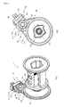
Fig. 4] Fig. 4(a) and Fig. 4(b) illustrate a third embodiment of the present invention and correspond toFig. 1(a) and Fig. 1(b) , respectively. - [
Fig. 5] Fig. 5 illustrates a seatbelt apparatus described inPTL 1. - [
Fig. 6] Fig. 6 illustrates a partial cross section of a seatbelt retractor described inPTL 1. - [
Fig. 7] Fig. 7(a) illustrates annularly arranged magnets of a rotation sensor described inPTL 1,Fig. 7(b) is a partial view corresponding to part VIIB ofFig. 7(a) and partially illustrating the rotation sensor described inPTL 1, andFig. 7(c) is a cross-sectional view taken along line VIIC-VIIC ofFig. 7(b) . - [
Fig. 8] Fig. 8 illustrates how the rotation sensor detects rotation. - Hereinafter, embodiments of the present invention will be described with reference to the drawings.
Fig. 1(a) is a perspective view partially illustrating a first embodiment of a seatbelt retractor according to the present invention, andFig. 1(b) is a right side view ofFig. 1(a) . In a seatbelt retractor and a seatbelt apparatus according to each of the following embodiments, components identical to those in previous embodiments and those of the seatbelt retractor and the seatbelt apparatus described in PTL 1 (illustrated inFig. 5 to Fig. 8 ) are given the same reference numerals and their detailed description will be omitted. - As illustrated in
Fig. 1(a) and Fig. 1(b) , a seatbelt retractor 3 of the first embodiment includes arotation sensor 15 serving as a rotation detecting member. Therotation sensor 15 is disposed eccentrically with respect to arotating shaft 10a of aspool 10. Therotation sensor 15 includes arotating disk 18 rotatably attached to a right side wall 9b of a frame, and abracket 19 immovably attached to the right side wall 9b of the frame. - The
rotating disk 18 includes an annularmagnet holding member 22 and annularly arrangedmagnets 21 rotatable integrally with themagnet holding member 22. The annularly arrangedmagnets 21 include N-pole magnets 21a and S-pole magnets 21b arranged alternately. Themagnet holding member 22 is integral with a tubular transmitting gear 23 (corresponding to a receiving member) havingexternal teeth 23a arranged concentrically with themagnet holding member 22. - A transmitting gear 24 (corresponding to a transmitting member) is mounted through a
bushing 10b on therotating shaft 10a of thespool 10 so as to be concentric with and rotatable integrally with therotating shaft 10a. The transmittinggear 24 hasexternal teeth 24a, which engage with theexternal teeth 23a of the receivinggear 23. - While not shown in
Fig. 1(a) and Fig. 1(b) , as in therotation sensor 15 described inPTL 1, a pair of Hall elements (Hall ICs) 20 serving as a magnet detecting member is attached to thebracket 19 so as to face some of themagnets 21. TheHall elements 20 detectmagnets 21 located at respective predetermined positions. - In the seatbelt retractor 3 of the first embodiment, the
rotation sensor 15 is disposed in a radial direction of the transmitting gear 24 (or in a radial direction of therotating shaft 10a). As illustrated inFig. 2 , theexternal teeth 23a of the receivinggear 23 engage with theexternal teeth 24a of the transmittinggear 24 at a position in a direction in which the transmitting gear 24 (or therotating shaft 10a) is moved away (or separated) from the receiving gear 23 (or the rotation sensor 15) by a large load F applied from theseatbelt 4 to thespool 10 in an emergency. - In the seatbelt retractor 3 of the first embodiment, a gear ratio between the
external teeth 23a of the receivinggear 23 of therotation sensor 15 and theexternal teeth 24a of the transmittinggear 24 is set such that the speed of rotation of the receiving gear 23 (or rotation of the magnets 21) is faster than that of rotation of the transmitting gear 24 (or rotation of the spool 10). That is, the receivinggear 23 and the transmittinggear 24 constitute aspeed increasing mechanism 25 which is a gear mechanism that increases the speed of rotation of thespool 10 at a predetermined speed-doubling rate to rotate themagnets 21. Therefore, thespeed increasing mechanism 25 is disposed between therotation sensor 15 and therotating shaft 10a of thespool 10.
The other configurations of the seatbelt retractor 3 and the configuration of aseatbelt apparatus 1 according to the first embodiment are the same as those of the seatbelt retractor 3 and theseatbelt apparatus 1 described inPTL 1. - In the seatbelt retractor 3 of the first embodiment configured as described above, the
rotation sensor 15 is disposed eccentrically with respect to therotating shaft 10a of thespool 10 in a radial direction of therotating shaft 10a, and at a position in a direction in which thetransmitting gear 24 is separated from the receivinggear 23 by a large load F applied to thespool 10 in an emergency. Therefore, even if a large load F is applied from theseatbelt 4 to thespool 10 in an emergency, very little load F is transmitted to therotation sensor 15. - In the seatbelt retractor 3 of the first embodiment configured as described above, the
rotation sensor 15 is disposed eccentrically with respect to therotating shaft 10a of thespool 10 in a radial direction of therotating shaft 10a, and at a position in a direction in which thetransmitting gear 24 is separated from the receivinggear 23 by a large load F applied to thespool 10 in an emergency. Therefore, unlike the conventional example, therotation sensor 15 does not function as a bearing for thespool 10. Thus, even if a large load F is applied from theseatbelt 4 to thespool 10 in an emergency, it is possible to effectively suppress transmission of the large load F to therotation sensor 15. As a result, the size of therotation sensor 15 in the thrust direction (or in the axial direction of the spool 10) can be made smaller than that in the conventional example. In the seatbelt retractor 3 of the first embodiment, which includes thisrotation sensor 15, it is possible to effectively suppress an increase in size of the seatbelt retractor 3 in the thrust direction even if there is therotation sensor 15. In particular, since therotation sensor 15 is disposed eccentrically with respect to therotating shaft 10a of thespool 10 in a radial direction of therotating shaft 10a, it is possible to more effectively suppress an increase in size of the seatbelt retractor 3 in the thrust direction. - Moreover, since the transmission of the large load F to the
rotation sensor 15 can be suppressed, it is possible to suppress influence of the load F on therotation sensor 15. It is thus possible to improve detection accuracy of therotation sensor 15.
Additionally, if a large deceleration is exerted on the vehicle in an emergency, since an inertial force of the occupant applied to theseatbelt 4 is directed substantially forward, the direction of the load F is substantially constant. Therefore, it is possible to easily set the installation position of therotation sensor 15. - It is thus possible to realize a seatbelt retractor that can improve detection accuracy of the
rotation sensor 15, reduce a load applied to therotation sensor 15, and suppress an increase in size in the thrust direction. - The
speed increasing mechanism 25 that increases the speed of rotation of thespool 10 at a predetermined speed-doubling rate to rotate themagnets 21 is disposed between therotation sensor 15 and therotating shaft 10a of thespool 10. Thus, since the amount of rotation of themagnets 21 is larger than that of thespool 10, the circumferential length of each of the N-pole magnets 21a and S-pole magnets 21b can be set to be long. In other words, a reference angle to be detected by therotation sensor 15 can be made larger than a reference angle to be detected by the conventional rotation sensor. It is thus possible to effectively reduce variation in detection of therotation sensor 15. Therefore, it is possible to more effectively improve detection accuracy of therotation sensor 15. - In the
seatbelt apparatus 1 according to the present invention, which includes the seatbelt retractor 3 of the first embodiment, it is possible to efficiently restrain an occupant with theseatbelt 4 for a long period of time depending on how the vehicle runs, how theseatbelt apparatus 1 is used, etc.
The other operational effects of the seatbelt retractor 3 and the operational effect of theseatbelt apparatus 1 according to the first embodiment are the same as those of the seatbelt retractor 3 and theseatbelt apparatus 1 described inPTL 1. -
Fig. 3 illustrates a second embodiment of the present invention and corresponds toFig. 2 .
In the first embodiment illustrated inFig. 1 andFig. 2 , the transmittinggear 24 has theexternal teeth 24a and theexternal teeth 23a of the receivinggear 23 of therotation sensor 15 are configured to engage with theexternal teeth 24a of the transmittinggear 24. In the seatbelt retractor 3 of the second embodiment, as illustrated inFig. 3 , the transmittinggear 24 is an internal gear havinginternal teeth 24b. Then, theexternal teeth 23a of the receivinggear 23 engage with theinternal teeth 24b of the transmittinggear 24. In this case, theexternal teeth 23a and theinternal teeth 24b constitute thespeed increasing mechanism 25. As in the first embodiment, therotation sensor 15 is disposed eccentrically with respect to therotating shaft 10a of thespool 10 in a radial direction of therotating shaft 10a, and at a position in a direction in which thetransmitting gear 24 is separated from the receivinggear 23 by a large load F applied to thespool 10 in an emergency.
The other configurations and operational effects of the seatbelt retractor 3 of the second embodiment are substantially the same as those of the first embodiment illustrated inFig. 1 andFig. 2 . -
Fig. 4(a) and Fig. 4(b) illustrate a third embodiment of the present invention and correspond toFig. 1(a) and Fig. 1(b) , respectively.
In the first and second embodiments described above, thespeed increasing mechanism 25 is a gear mechanism composed of the receivinggear 23 of therotation sensor 15 and the transmittinggear 24 secured to therotating shaft 10a of thespool 10. In the seatbelt retractor 3 of the third embodiment, as illustrated inFig. 4(a) and Fig. 4(b) , thespeed increasing mechanism 25 is constituted by abelt transmission mechanism 29. Specifically, in the third embodiment, instead of the receivinggear 23 of the first embodiment, a receivingpulley 30 is mounted on themagnet holding member 22 of therotation sensor 15 in the same manner as the receivinggear 23. Also, instead of the transmittinggear 24 of the first embodiment, a transmittingpulley 31 is mounted on therotating shaft 10a of thespool 10 in the same manner as the transmittinggear 24. Additionally, anendless belt 32 is wound around the receivingpulley 30 and the transmittingpulley 31. That is, thebelt transmission mechanism 29 is composed of the receivingpulley 30, the transmittingpulley 31, and theendless belt 32. An endless-belt-winding radius of the transmittingpulley 31 is set to be larger than that of the receivingpulley 30. Thus, the rotation of thespool 10 is speeded up and transmitted to themagnets 21, so that the rotation speed of themagnets 21 is larger than that of thespool 10.
The other configurations and operational effects of the seatbelt retractor 3 and theseatbelt apparatus 1 of the third embodiment are substantially the same as those of the first embodiment. - The present invention is not limited to the embodiments described above, and various design changes can be made within the scope of technical matters described in the claims.
- The seatbelt retractor and the seatbelt apparatus according to the present invention may be used as a seatbelt retractor and a seatbelt apparatus including the same in which an electric motor drives and controls rotation of a spool to retract and withdraw a seatbelt. In particular, the seatbelt retractor and the seatbelt apparatus according to the present invention may be suitably used as a seatbelt retractor and a seatbelt apparatus including the same that include a rotation detecting member configured to detect the amount of rotation of a spool.
Claims (7)
- A seatbelt retractor comprising at least a spool configured to retract a seatbelt; drive means for rotating the spool; and a rotation detecting member configured to detect the amount of rotation of the spool, the amount of rotation of the spool being controlled by driving and controlling the drive means on the basis of the amount of rotation of the spool detected by the rotation detecting member,
wherein the rotation detecting member is disposed eccentrically with respect to a rotating shaft of the spool in a radial direction of the rotating shaft. - The seatbelt retractor according to Claim 1, wherein the rotation detecting member is disposed in a direction in which the rotating shaft is separated from the rotation detecting member by a load applied from the seatbelt to the spool in an emergency.
- The seatbelt retractor according to Claim 1 or 2, wherein the rotation detecting member includes a rotating disk that includes a predetermined number of magnets and a receiving member rotatable integrally with the predetermined number of magnets, the predetermined number of magnets including N-pole magnets and S-pole magnets alternately and annularly arranged concentrically with the rotating disk,
the seatbelt retractor further comprising a transmitting member configured to transmit rotation of the spool to the receiving member, the transmitting member being mounted on the spool so as to be rotatable integrally with the spool; and
a magnet detecting member configured to detect a magnet located at a predetermined position, the magnet being any of the predetermined number of magnets. - The seatbelt retractor according to Claim 3, further comprising a speed increasing mechanism configured to increase a rotation speed of the transmitting member to transmit the rotation speed to the receiving member, and increase a rotation speed of the spool to rotate the magnets.
- The seatbelt retractor according to Claim 4, wherein the receiving member is a receiving gear and the transmitting member is a transmitting gear that engages with the receiving gear; and
the speed increasing mechanism is composed of the receiving gear and the transmitting gear. - The seatbelt retractor according to Claim 4, wherein the receiving member is a receiving pulley and the transmitting member is a transmitting pulley; and
the speed increasing mechanism is composed of the receiving pulley, the transmitting pulley, and an endless belt wound around the receiving pulley and the transmitting pulley. - A seatbelt apparatus comprising at least a seatbelt retractor configured to retract a seatbelt; a tongue slidably supported by the seatbelt withdrawn from the seatbelt retractor; and a buckle with which the tongue is engageably and disengageably engaged, the seatbelt apparatus being configured to restrain an occupant with the seatbelt,
wherein the seatbelt retractor is a seatbelt retractor according to any one of Claims 1 to 6.
Applications Claiming Priority (2)
| Application Number | Priority Date | Filing Date | Title |
|---|---|---|---|
| JP2010017836A JP5450131B2 (en) | 2010-01-29 | 2010-01-29 | Seat belt retractor and seat belt device provided with the same |
| PCT/JP2010/007206 WO2011092787A1 (en) | 2010-01-29 | 2010-12-10 | Seatbelt retractor and seatbelt device provided with same |
Publications (2)
| Publication Number | Publication Date |
|---|---|
| EP2529982A1 true EP2529982A1 (en) | 2012-12-05 |
| EP2529982A4 EP2529982A4 (en) | 2013-07-03 |
Family
ID=44318800
Family Applications (1)
| Application Number | Title | Priority Date | Filing Date |
|---|---|---|---|
| EP10844555.2A Ceased EP2529982A4 (en) | 2010-01-29 | 2010-12-10 | Seatbelt retractor and seatbelt device provided with same |
Country Status (5)
| Country | Link |
|---|---|
| US (1) | US8960585B2 (en) |
| EP (1) | EP2529982A4 (en) |
| JP (1) | JP5450131B2 (en) |
| CN (1) | CN102712292B (en) |
| WO (1) | WO2011092787A1 (en) |
Families Citing this family (11)
| Publication number | Priority date | Publication date | Assignee | Title |
|---|---|---|---|---|
| JP5462070B2 (en) * | 2010-05-17 | 2014-04-02 | タカタ株式会社 | Position detection device, seat belt retractor provided with the position detection device, and seat belt device provided with the seat belt retractor |
| DE102013004784A1 (en) * | 2013-03-20 | 2014-09-25 | Trw Automotive Gmbh | Belt retractor with angle of rotation determination |
| DE102014018262B4 (en) * | 2014-12-11 | 2021-08-05 | Zf Automotive Germany Gmbh | Belt retractor with a signal transmitter ring |
| EP3199410B1 (en) * | 2016-01-29 | 2019-03-27 | Autoliv Development AB | Control method for an electric seatbelt retractor and electric seatbelt retractor |
| KR101766139B1 (en) * | 2016-05-11 | 2017-08-07 | 현대자동차주식회사 | Motorized seat-belt system |
| DE102017122459A1 (en) * | 2017-09-27 | 2019-03-28 | Trw Automotive Gmbh | Method for measuring the webbing extension and webbing retractor |
| KR102391718B1 (en) * | 2018-02-02 | 2022-04-28 | 아우토리브 디벨롭먼트 아베 | seat belt device |
| US10829085B2 (en) * | 2018-02-18 | 2020-11-10 | Joyson Safety Systems Acquisition Llc | Seat belt retractor |
| US10994696B2 (en) * | 2018-10-02 | 2021-05-04 | GM Global Technology Operations LLC | System and method determining seatbelt webbing payout |
| EP3870127A1 (en) * | 2018-10-26 | 2021-09-01 | Valeda Company, LLC | Occupancy sensor for wheeled mobility device restraint |
| CN110670234B (en) * | 2019-11-02 | 2024-10-15 | 徐州恒辉编织机械有限公司 | Constant tension paying-off device of multifunctional oversized-stroke yarn storage and release device |
Family Cites Families (17)
| Publication number | Priority date | Publication date | Assignee | Title |
|---|---|---|---|---|
| DE19922720A1 (en) | 1999-05-18 | 2000-11-30 | Trw Repa Gmbh | Belt spooler for vehicle occupant restraint system has incremental counter coupled to belt calibrated using control plate sensor so counter state represents absolute rotation angle of spool |
| DE29908716U1 (en) | 1999-05-18 | 1999-09-23 | TRW Occupant Restraint Systems GmbH & Co. KG, 73553 Alfdorf | Belt retractor |
| JP2001151076A (en) * | 1999-11-29 | 2001-06-05 | Takata Corp | Occupant restraint protection system |
| DE19957814C2 (en) * | 1999-12-01 | 2003-07-31 | Trw Automotive Electron & Comp | Gurtaufrollersystem |
| DE20311004U1 (en) * | 2003-07-17 | 2003-12-04 | Trw Occupant Restraint Systems Gmbh & Co. Kg | Belt retractor for a vehicle seat belt |
| JP2005297675A (en) * | 2004-04-08 | 2005-10-27 | Tokai Rika Co Ltd | Webbing take-up device |
| JP4034754B2 (en) | 2004-04-12 | 2008-01-16 | オートリブ ディベロップメント エービー | Seat belt retractor and seat belt device |
| JP2006218984A (en) * | 2005-02-09 | 2006-08-24 | Takata Corp | Seat belt retractor, seat belt device, and vehicle with seat belt device |
| JP2007326513A (en) | 2006-06-09 | 2007-12-20 | Takata Corp | Seat belt retractor and seat belt device provided with the same |
| DE102006032066A1 (en) | 2006-07-11 | 2008-01-24 | Trw Automotive Gmbh | Belt retractor for a safety belt system and method for determining the webbing withdrawal in a belt retractor |
| DE102006036554B4 (en) | 2006-08-04 | 2020-02-06 | Trw Automotive Gmbh | Belt retractor for a seat belt system |
| DE102006037735B4 (en) | 2006-08-11 | 2020-07-30 | Trw Automotive Gmbh | Belt retractor for a seat belt system |
| DE102006051969A1 (en) * | 2006-11-03 | 2008-05-15 | Trw Automotive Gmbh | Belt retractor for a safety belt system |
| JP5215549B2 (en) * | 2006-11-24 | 2013-06-19 | タカタ株式会社 | Seat belt retractor |
| US8141808B2 (en) | 2007-03-26 | 2012-03-27 | Autoliv Development Ab | Seat belt device |
| JP5191213B2 (en) | 2007-11-08 | 2013-05-08 | タカタ株式会社 | Seat belt retractor and seat belt device provided with the same |
| JP2008275636A (en) * | 2008-06-18 | 2008-11-13 | Takata Corp | Rotary sensor |
-
2010
- 2010-01-29 JP JP2010017836A patent/JP5450131B2/en not_active Expired - Fee Related
- 2010-12-10 WO PCT/JP2010/007206 patent/WO2011092787A1/en not_active Ceased
- 2010-12-10 US US13/522,916 patent/US8960585B2/en not_active Expired - Fee Related
- 2010-12-10 EP EP10844555.2A patent/EP2529982A4/en not_active Ceased
- 2010-12-10 CN CN201080062147.3A patent/CN102712292B/en not_active Expired - Fee Related
Also Published As
| Publication number | Publication date |
|---|---|
| US8960585B2 (en) | 2015-02-24 |
| CN102712292B (en) | 2015-05-20 |
| US20120292417A1 (en) | 2012-11-22 |
| CN102712292A (en) | 2012-10-03 |
| JP2011156889A (en) | 2011-08-18 |
| JP5450131B2 (en) | 2014-03-26 |
| EP2529982A4 (en) | 2013-07-03 |
| WO2011092787A1 (en) | 2011-08-04 |
Similar Documents
| Publication | Publication Date | Title |
|---|---|---|
| US8960585B2 (en) | Seatbelt retractor and seatbelt apparatus including the same | |
| JP5462070B2 (en) | Position detection device, seat belt retractor provided with the position detection device, and seat belt device provided with the seat belt retractor | |
| US8104794B2 (en) | Seat belt retractor, seat belt apparatus, seat belt winding method, computer program, and seat belt system | |
| EP1524159B1 (en) | Seat belt retractor | |
| US6702326B1 (en) | Passenger restraining protective system | |
| US11338764B2 (en) | Restraining system for a seat belt buckle | |
| EP2711252B1 (en) | Seat belt device | |
| JP4640963B2 (en) | Seat belt retractor and seat belt device provided with the same | |
| EP1777127A1 (en) | Seat belt retractor, seat belt apparatus, and vehicle with seat belt apparatus | |
| CN108602487B (en) | Control method for electric seat belt retractor and electric seat belt retractor | |
| JP5388359B2 (en) | Seat belt retractor and seat belt device provided with the same | |
| JP5005616B2 (en) | Slip joint | |
| EP1749714B1 (en) | Seatbelt retractor and seatbelt system having the same | |
| JP6737667B2 (en) | Seat belt retractor | |
| JP4890288B2 (en) | Vehicle seat belt device | |
| EP2154034B1 (en) | Seat belt retractor, and seat belt device having the retractor | |
| JP5557697B2 (en) | Seat belt device | |
| JP6657397B2 (en) | Seat belt retractor and seat belt system | |
| JP6773468B2 (en) | Seat belt retractor | |
| JP2020114738A (en) | Seat belt retractor | |
| JP6708506B2 (en) | Seat belt retractor |
Legal Events
| Date | Code | Title | Description |
|---|---|---|---|
| PUAI | Public reference made under article 153(3) epc to a published international application that has entered the european phase |
Free format text: ORIGINAL CODE: 0009012 |
|
| 17P | Request for examination filed |
Effective date: 20120704 |
|
| AK | Designated contracting states |
Kind code of ref document: A1 Designated state(s): AL AT BE BG CH CY CZ DE DK EE ES FI FR GB GR HR HU IE IS IT LI LT LU LV MC MK MT NL NO PL PT RO RS SE SI SK SM TR |
|
| DAX | Request for extension of the european patent (deleted) | ||
| A4 | Supplementary search report drawn up and despatched |
Effective date: 20130603 |
|
| RIC1 | Information provided on ipc code assigned before grant |
Ipc: B60R 22/48 20060101AFI20130527BHEP |
|
| 17Q | First examination report despatched |
Effective date: 20140131 |
|
| APBK | Appeal reference recorded |
Free format text: ORIGINAL CODE: EPIDOSNREFNE |
|
| APBN | Date of receipt of notice of appeal recorded |
Free format text: ORIGINAL CODE: EPIDOSNNOA2E |
|
| APBR | Date of receipt of statement of grounds of appeal recorded |
Free format text: ORIGINAL CODE: EPIDOSNNOA3E |
|
| APAF | Appeal reference modified |
Free format text: ORIGINAL CODE: EPIDOSCREFNE |
|
| APBT | Appeal procedure closed |
Free format text: ORIGINAL CODE: EPIDOSNNOA9E |
|
| REG | Reference to a national code |
Ref country code: DE Ref legal event code: R003 |
|
| STAA | Information on the status of an ep patent application or granted ep patent |
Free format text: STATUS: THE APPLICATION HAS BEEN REFUSED |
|
| 18R | Application refused |
Effective date: 20161005 |