EP2529980B1 - Bumper reinforcement structure - Google Patents
Bumper reinforcement structure Download PDFInfo
- Publication number
- EP2529980B1 EP2529980B1 EP10844957.0A EP10844957A EP2529980B1 EP 2529980 B1 EP2529980 B1 EP 2529980B1 EP 10844957 A EP10844957 A EP 10844957A EP 2529980 B1 EP2529980 B1 EP 2529980B1
- Authority
- EP
- European Patent Office
- Prior art keywords
- panel section
- vehicle
- bumper reinforcement
- section
- rear panel
- Prior art date
- Legal status (The legal status is an assumption and is not a legal conclusion. Google has not performed a legal analysis and makes no representation as to the accuracy of the status listed.)
- Not-in-force
Links
- 230000002787 reinforcement Effects 0.000 title claims description 77
- 239000011324 bead Substances 0.000 claims description 18
- 238000006073 displacement reaction Methods 0.000 claims description 13
- 238000005304 joining Methods 0.000 claims description 6
- 238000012986 modification Methods 0.000 description 7
- 230000004048 modification Effects 0.000 description 7
- 230000000694 effects Effects 0.000 description 6
- 238000003466 welding Methods 0.000 description 3
- 230000004888 barrier function Effects 0.000 description 2
- 238000004519 manufacturing process Methods 0.000 description 1
- 239000002184 metal Substances 0.000 description 1
- 238000000034 method Methods 0.000 description 1
- 238000009751 slip forming Methods 0.000 description 1
Images


Classifications
-
- B—PERFORMING OPERATIONS; TRANSPORTING
- B60—VEHICLES IN GENERAL
- B60R—VEHICLES, VEHICLE FITTINGS, OR VEHICLE PARTS, NOT OTHERWISE PROVIDED FOR
- B60R19/00—Wheel guards; Radiator guards, e.g. grilles; Obstruction removers; Fittings damping bouncing force in collisions
- B60R19/02—Bumpers, i.e. impact receiving or absorbing members for protecting vehicles or fending off blows from other vehicles or objects
- B60R19/18—Bumpers, i.e. impact receiving or absorbing members for protecting vehicles or fending off blows from other vehicles or objects characterised by the cross-section; Means within the bumper to absorb impact
-
- B—PERFORMING OPERATIONS; TRANSPORTING
- B60—VEHICLES IN GENERAL
- B60R—VEHICLES, VEHICLE FITTINGS, OR VEHICLE PARTS, NOT OTHERWISE PROVIDED FOR
- B60R19/00—Wheel guards; Radiator guards, e.g. grilles; Obstruction removers; Fittings damping bouncing force in collisions
- B60R19/02—Bumpers, i.e. impact receiving or absorbing members for protecting vehicles or fending off blows from other vehicles or objects
- B60R19/04—Bumpers, i.e. impact receiving or absorbing members for protecting vehicles or fending off blows from other vehicles or objects formed from more than one section in a side-by-side arrangement
- B60R19/12—Bumpers, i.e. impact receiving or absorbing members for protecting vehicles or fending off blows from other vehicles or objects formed from more than one section in a side-by-side arrangement vertically spaced
-
- B—PERFORMING OPERATIONS; TRANSPORTING
- B60—VEHICLES IN GENERAL
- B60R—VEHICLES, VEHICLE FITTINGS, OR VEHICLE PARTS, NOT OTHERWISE PROVIDED FOR
- B60R19/00—Wheel guards; Radiator guards, e.g. grilles; Obstruction removers; Fittings damping bouncing force in collisions
- B60R19/02—Bumpers, i.e. impact receiving or absorbing members for protecting vehicles or fending off blows from other vehicles or objects
- B60R19/18—Bumpers, i.e. impact receiving or absorbing members for protecting vehicles or fending off blows from other vehicles or objects characterised by the cross-section; Means within the bumper to absorb impact
- B60R2019/186—Additional energy absorbing means supported on bumber beams, e.g. cellular structures or material
Definitions
- the present invention relates to a bumper reinforcement structure.
- Patent Document 1 describes a vehicle front section structure equipped with a bumper beam extending in the vehicle width direction and an impact absorbing member provided at the front side of the bumper beam.
- the impact absorbing member is formed higher than the height of the bumper beam. Accordingly, during vehicle frontal impact, impact load can be absorbed well by the impact absorbing member even for different heights of impact bodies.
- US 2004/0130166 A1 discloses a bumper beam consisting of a profile made of a single folded metal sheet blank.
- the present invention is made in consideration of the above issue, and has an object of providing a bumper reinforcement structure that can ensure a vehicle top-bottom direction deformation stroke with the impact body in the vehicle front section when an impact load is input to the vehicle front section from both the vehicle front side and the vehicle top side, while still ensuring impact resistance during vehicle frontal impact.
- a bumper reinforcement structure includes: a bumper reinforcement to be provided to a vehicle front section and extending in the vehicle width direction; an upper member, being separate from and fixed to the bumper reinforcement and including a front panel section joined to the bumper reinforcement, a top panel section connected to a top edge portion of the front panel section, and a rear panel section connected to a rear edge portion of the top panel section, the upper member being formed with a C-shaped cross-section opening towards the vehicle bottom side, the upper member forming a closed cross-section portion with a top wall portion of the bumper reinforcement at the vehicle top side of the bumper reinforcement; and a displacement facilitation portion provided to the rear panel section, the displacement facilitation portion allowing the top panel section to displace towards the vehicle bottom side when an impact load is input with respect to the top panel section from both the vehicle front side and the vehicle top side.
- the top panel section displaces towards the vehicle bottom side due to the displacement facilitation portion. Accordingly, a vehicle top-bottom direction deformation stroke with the impact body in the vehicle front section can be ensured.
- a sloping portion is formed at least at the front edge portion side of the top panel section, sloping with respect to the vehicle front-rear direction so as to face toward both the vehicle front side and the vehicle top side.
- the sloping portion is formed at least at the front edge portion side of the top panel section, with the sloping portion sloping with respect to the vehicle horizontal direction so as to face both the vehicle front side and the vehicle top side. Consequently, since the impact load is input substantially perpendicularly to the sloping portion when the impact body impacts the vehicle front section from both the vehicle front side and the vehicle top side, and hence the impact load can be efficiently transmitted to the displacement facilitation portion. Accordingly, the top panel section can be efficiently displaced towards the vehicle bottom side.
- the displacement facilitation portion is a joint portion that joins the rear panel section and a rear wall portion of the bumper reinforcement, and the joined state of the rear panel section and the rear wall portion is released when an impact load is input with respect to the top panel section from both the vehicle front side and the vehicle top side.
- the top panel section when an impact load is input with respect to the top panel section from both the vehicle front side and the vehicle top side, the top panel section can be displaced together with the rear panel section towards the vehicle bottom side by the joined state of the rear panel section and the rear wall portion being released.
- the joint portion is configured to be a fastening structure including a fastener that passes though the rear panel section and the rear wall portion and fastens the rear panel section and the rear wall portion together, and an escape hole formed continuously toward the vehicle top side from the position of the fastener in the rear panel section.
- the fastening structure includes a latching portion formed further to the vehicle top side than the position of the fastener in the rear panel section, with the latching portion latching the fastener.
- the fastener since the fastener is latched by the latching portion during normal operation, the fastener can be suppressed from relative movement towards the top edge portion side of the escape hole.
- the fastener moves past the latching portion when an impact load is input with respect to the top panel section from both the vehicle front side and the vehicle top side, and due thereto, the fastener can be caused to move relatively towards the top edge portion side of the escape hole.
- the joint portion is configured to be a rear weld portion that joins the rear panel section to the rear wall portion with a weld strength lower than that of a front weld portion that joins the front panel section to the bumper reinforcement.
- the displacement facilitation portion is configured to be a deformation origin point portion that acts as the origin point for deformation of the rear panel section such that the rear panel section is compressively deformed, when an impact load is input with respect to the top panel section from both the vehicle front side and the vehicle top side.
- the top panel section when an impact load is input with respect to the top panel section from both the vehicle front side and the vehicle top side, the top panel section can be displaced towards the vehicle bottom side by the rear panel section being compressively deformed with the deformation origin point portion acting as the origin point.
- the deformation origin portion is configured to be a bead formed between the joint portion joining the rear panel section with the rear wall portion of the bumper reinforcement and a top edge portion of the rear panel section, and extending in the vehicle width direction.
- a vehicle top-bottom direction deformation stroke with the impact body in the vehicle front section is ensured when an impact load is input to the vehicle front section from both the vehicle front side and the vehicle top side, while still ensuring impact resistance during vehicle frontal impact.
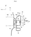
- the arrow UP, the arrow FR and the arrow OUT indicate the top side in a vehicle top-bottom direction, the front side in a vehicle front-rear direction and the vehicle width direction outside (left side), respectively.
- a vehicle front section 10 is configured with a bumper reinforcement 12, an upper member 14, a bumper cover 16, a grill 18, a hood 20, a radiator support 22 and a hood lock 24.
- the bumper reinforcement 12 and the upper member 14 together configure a bumper reinforcement structure 30 according to the first exemplary embodiment of the present exemplary embodiment.
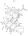
- the bumper reinforcement 12 is formed in a hollow shape, extending in the vehicle width direction, as shown in Fig. 2 .
- a central section 12A of the bumper reinforcement 12 is formed parallel to the vehicle width direction, left and right end sections 12B of the bumper reinforcement 12 are formed so as to bend around towards the vehicle rear side with respect to the central section 12A.
- the upper member 14 is provided to the central section 12A of the bumper reinforcement 12 so as to extend along the vehicle width direction, and has a front panel section 32, a top panel section 34 and a rear panel section 36.
- the top panel section 34 is formed connected to a top edge portion of the front panel section 32
- the rear panel section 36 is formed connected to a rear edge portion of the top panel section 34.
- the upper member 14 is thereby formed with a C-shaped cross-section, opening towards the vehicle bottom side.
- Plural holes 48 are formed in a lower portion of the front panel section 32, in a row along the vehicle width direction, and holes 50 are formed in an upper portion of a front wall portion 42 of the bumper reinforcement 12 at positions for fitting together with the respective holes 48.
- Nuts 52 are provided on the inside face of the front wall portion 42, coaxial to each of the holes 50.
- the front panel section 32 is fastened to the front wall portion 42 by inserting bolts 54 into the holes 48, 50 from the vehicle front side, and screwing the bolts 54 into the nuts 52.
- Plural elongated holes 58 are formed in the rear panel section 36, in a row along the vehicle width direction. Each of the respective elongated holes 58 has an elongated shape extending along the vehicle top-bottom direction. Holes 60 are formed in an upper portion of a rear wall portion 46 of the bumper reinforcement 12 at positions for fitting together with lower edge portions 58A of the elongated holes 58. Nuts 62 are provided at the inside face of the rear wall portion 46, coaxial to the holes 60. The rear panel section 36 is fastened to the rear wall portion 46 by inserting bolts 64 into the lower edge portions of the elongated holes 58 and the holes 60 from the vehicle rear side, and screwing the bolts 64 into the nuts 62.
- a constricted portion 68 is formed in the rear panel section 36, further towards the vehicle top side than the lower edge portion 58A of each of the elongated holes 58.
- the gap dimension at the constricted portion 68 is set so as to be just slightly smaller than the external diameter dimension of shaft portions of the bolts 64.
- the width dimension of the elongated holes 58 is set so as to be larger than the external diameter dimension of the shaft portion of the bolts 64, and smaller than the external diameter dimension of heads of the bolts 64. Configuration is made such that the constricted portions 68 are latched from the vehicle top side by the bolts 64 when the rear panel section 36 and the rear wall portion 46 are in a fastened state due to the bolts 64.
- the portions of the elongated holes 58 upper than the constricted portions 68 configure escape holes 58B.
- a fastening structure 72 configured by the above elongated hole 58 (escape hole 58B) and the bolt 64, corresponding to a fastener of the present invention, corresponds to a displacement facilitation portion and a joint portion of the present invention.
- the bolts 64 pass through the rear panel section 36 and the rear wall portion 46, and fasten the rear panel section 36 and the rear wall portion 46 together, with the escape holes 58B continuously formed toward the vehicle top side from the positions of the bolts 64 at the rear panel section 36.
- the constricted portions 68 correspond to a latching portion of the present invention.
- the upper member 14 attached to the bumper reinforcement 12 as described above forms a closed cross-section portion 74 with a top wall portion 44 of the bumper reinforcement 12 at the vehicle top side of the bumper reinforcement 12.
- a sloping portion 34A is formed at the front edge side of the top panel section 34.
- the sloping portion 34A slopes with respect to the vehicle front-rear direction so as to face both the vehicle front side and the vehicle top side.
- the closed cross-section portion 74 is formed by the upper member 14 at the vehicle top side of the bumper reinforcement 12. Consequently, as shown in Fig. 3 , due to configuration with the upper member 14 and the bumper reinforcement 12, the overlap amount OL with an impact body 100 in the vehicle top-bottom direction from the vehicle front side can be increased in comparison to cases configured with only the bumper reinforcement 12.
- the impact resistance of the vehicle front section10 during frontal impact namely capability to prevent, for example, under-riding in which the vehicle dives below an oncoming vehicle, can be ensured.
- the bolts 64 then pass the constricted portions 68 and move relatively towards the top edge portion side of the escape holes 58B, and the top panel section 34, together with the rear panel section 36, are displaced towards the vehicle bottom side with the top edge portion of the front panel section 32 acting as an origin point. Consequently, a vehicle top-bottom direction deformation stroke with the impact body 102 at the vehicle front section 10 can be ensured, therefore, capability to protect pedestrians can also be ensured. Note that in this case the deformation stroke continues until the shaft portions of the bolts 64 contact the top edge portions of the escape holes 58B.
- the sloping portion 34A is formed at the front edge side of the top panel section 34, and the sloping portion 34A is sloped with respect to the vehicle horizontal direction so as to face both the vehicle front side and the vehicle top side. Consequently, for example, in cases where an impact body 102 such as the femoral region of a pedestrian has impacted the vehicle front section 10, an impact load F is input substantially perpendicularly to the sloping portion 34A, and hence this impact load can be transmitted to the fastening structure 72 with good efficiency. Accordingly, the top panel section 34 can be displaced more efficiently towards the vehicle bottom side.
- the bolts 64 are latched by the constricted portions 68, the bolts 64 can be prevented from relatively moving towards the top edge portion side of the escape holes 58B.
- the above impact body 100 is presumed to be a barrier in a minimal wrap barrier crash test.
- the elongated holes 58 are formed in the rear panel section 36 and the holes 60 are formed in the rear wall portion 46
- configuration may be made with the elongated holes 58 formed in the rear wall portion 46 and the holes 60 formed in the rear panel section 36 in positions for fitting to the top edge portion of the elongated holes 58.
- the rear panel section 36 may then be fastened to the rear wall portion 46 with the bolts 64 in an inserted state into the top edge portion of the elongated holes 58 and the holes 60.
- bolts 64 and the nuts 62 are employed for fastening the rear panel section 36 and the rear wall portion 46 together, configuration may be made employing other fasteners, such as, for example, rivets or the like.
- sloping portion 34A is formed at the front edge side of the top panel section 34, configuration may be made with the sloping portion 34A formed over the entire top panel section 34.
- the elongated holes 58 may be configured as slot shapes.
- front panel section 32 and the front wall portion 42 are fastened by the bolts 54 and the nuts 52
- configuration may be made with the front panel section 32 and the front wall portion 42 joined by, for example, welding.
- front panel section 32 is joined to the front wall portion 42
- configuration may be made such that, for example, the front panel section 32 is joined by welding or the like to a front portion of the top wall portion 44.
- a bumper reinforcement structure 80 according to a second exemplary embodiment of the present invention differs in fastening structure of the upper member 14 and the bumper reinforcement 12 from the bumper reinforcement structure 30 according to the first exemplary embodiment of the present invention in the following manner.
- the bottom marginal portion of the front panel section 32 is joined to the front wall portion 42 by a front weld portion 81.
- the front weld portion 81 is formed in the vehicle width direction along the entire length of the bottom marginal portion of the front panel section 32.
- the bottom marginal portion of the rear panel section 36 is joined to the rear wall portion 46 by rear weld portions 82, as shown in Fig. 6 .
- the rear weld portions 82 are configured by plural weld portions 82A, 82B, 82C which are formed at intervals along the vehicle width direction. By making the total length of the rear weld portions 82, that of the combined plural weld portions 82A, 82B, 82C, shorter than the front weld portion 81, the weld strength of the rear weld portion 82 is also lower than that of the front weld portion 81.
- the front weld portion 81 and the rear weld portions 82 are both made by, for example, ark welding or the like.
- the rear weld portion 82 corresponds to the displacement facilitation portion and joint portion of the present invention.
- the bumper reinforcement structure 80 when an impact body, such as the femoral region of a pedestrian or the like, impacts the vehicle front section, and an impact load is input with respect to the top panel section 34 from both the vehicle front side and the vehicle top side, the fastened state of the rear panel section 36 and the rear wall portion 46 is released by the rear weld portions 82 breaking. Accordingly, the top panel section 34, together with the rear panel section 36, then are displaced towards the vehicle bottom side with the top edge portion of the front panel section 32 acting as an origin point. Consequently, since a vehicle top-bottom direction deformation stroke with the impact body at the vehicle front section can be ensured, and capability to protect pedestrians can also be ensured.
- an impact body such as the femoral region of a pedestrian or the like
- rear weld portions 82 are configured with the three weld portions 82A, 82B, 82C in the second exemplary embodiment of the present invention, configuration may be made with a number of weld portions other than three.
- front weld portion 81 is formed in the vehicle width direction along the entire length of the front panel section 32, as shown in Fig. 5 , configuration may be made with plural weld portions formed at intervals along the vehicle width direction.
- any mode may be adopted for the front weld portion 81 and the rear weld portions 82, as long as the weld strength of the rear weld portion(s) 82 is lower than that of the front weld portion(s) 81.
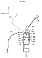
- a bumper reinforcement structure 90 according to a third exemplary embodiment of the present invention, illustrated in Fig. 7 , has a configuration of upper member 14 modified from that of the bumper reinforcement structure 30 according to the first exemplary embodiment of the present invention in the following manner.
- plural beads 92 are formed to the rear panel section 36 in a row in the vehicle top-bottom direction.
- the plural beads 92 are formed between holes 98, described later, and a top edge portion 36A of the rear panel section 36.
- Each of the beads 92 extends along the vehicle width direction, and both end portions of the beads 92 end further to the vehicle width direction inside than both vehicle width direction end portions 36B of the rear panel section 36.
- the holes 98 are formed in a lower portion of the rear panel section 36, as shown in Fig. 7 , in positions for fitting together with the holes 60.
- Bolts 64 are inserted into the holes 60, 98 and screwed into the nuts 62, and the rear panel section 36 is thereby portion 46.
- the above plural beads 92 correspond to the displacement facilitation portion and deformation origin portion of the present invention.
- the portion where the holes 98 are formed in the rear panel section 36 corresponds to the joint portion to the rear wall portion in the present invention.
- the bumper reinforcement structure 90 As shown in Fig. 10 , when the vehicle front section 10 is impacted by a impact body 102, such as for example the femoral region of a pedestrian, and an impact load F is input with respect to the top panel section 34 from both the vehicle front side and the vehicle top side, the rear panel section 36 buckles (performs compressive deformation) with the beads 92 acting as origin points. Then the top panel section 34 accordingly is displaced towards the vehicle bottom side with the top edge portion of the front panel section 32 acting as an origin point. Consequently, a vehicle top-bottom direction deformation stroke with the impact body 102 at the vehicle front section 10 can be ensured, and hence capability to protect pedestrians can also be ensured.
- a impact body 102 such as for example the femoral region of a pedestrian
- the plural beads 92 are formed to the rear panel section 36 so as to extend along the vehicle width direction, hence rigidity of the upper member 14 can be ensured even if the vehicle front section 10 is impacted by the impact body 100 from the vehicle front side.
- configuration may be made such that the beads 92 are open at the two vehicle width direction end portions 36B of the rear panel section 36, as shown in Fig. 11 .
- the rear panel section 36 can be made to buckle with the beads 92 acting as origin points when an impact load is input with respect to the top panel section 34 from both the vehicle front side and the vehicle top side.
- manufacture of the upper member 14 can be facilitated when both end portions of the beads 92 are open at the two vehicle width direction end portions 36B of the rear panel section 36.
- the beads 92 are formed in the rear panel section 36 as deformation origin point portions in the third exemplary embodiment of the present invention, configuration may be made with other portions than the beads 92, as long as they act as deformation origin points.
Landscapes
- Engineering & Computer Science (AREA)
- Mechanical Engineering (AREA)
- Body Structure For Vehicles (AREA)
Description
- The present invention relates to a bumper reinforcement structure.
-
Patent Document 1 describes a vehicle front section structure equipped with a bumper beam extending in the vehicle width direction and an impact absorbing member provided at the front side of the bumper beam. The impact absorbing member is formed higher than the height of the bumper beam. Accordingly, during vehicle frontal impact, impact load can be absorbed well by the impact absorbing member even for different heights of impact bodies.
US 2004/0130166 A1 discloses a bumper beam consisting of a profile made of a single folded metal sheet blank. - Patent Document 1:
JP 2009-35027 A - Patent Document 2:
JP 2003-252134 A - Patent Document 3:
JP 2007-261525 A - Patent Document 4:
JP 2008-080924 A claim 1. - However, in the example described in
Patent Document 1, when the flexural rigidity of the impact absorbing member is high, there is concern regarding it becoming difficult to ensure a vehicle top-bottom direction deformation stroke with an impact body in the vehicle front section when an impact load is input to the vehicle front section from both the vehicle front side and the vehicle top side, for example due to impact between the vehicle and the impact body such as the femoral region of a pedestrian. - The present invention is made in consideration of the above issue, and has an object of providing a bumper reinforcement structure that can ensure a vehicle top-bottom direction deformation stroke with the impact body in the vehicle front section when an impact load is input to the vehicle front section from both the vehicle front side and the vehicle top side, while still ensuring impact resistance during vehicle frontal impact.
- In order to address the above issue, a bumper reinforcement structure according to the present invention includes: a bumper reinforcement to be provided to a vehicle front section and extending in the vehicle width direction; an upper member, being separate from and fixed to the bumper reinforcement and including a front panel section joined to the bumper reinforcement, a top panel section connected to a top edge portion of the front panel section, and a rear panel section connected to a rear edge portion of the top panel section, the upper member being formed with a C-shaped cross-section opening towards the vehicle bottom side, the upper member forming a closed cross-section portion with a top wall portion of the bumper reinforcement at the vehicle top side of the bumper reinforcement; and a displacement facilitation portion provided to the rear panel section, the displacement facilitation portion allowing the top panel section to displace towards the vehicle bottom side when an impact load is input with respect to the top panel section from both the vehicle front side and the vehicle top side.
- According to such a bumper reinforcement structure, there is a closed cross-section portion formed by the upper member at the vehicle top side of the bumper reinforcement. Consequently, due to provision of both the upper member and the bumper reinforcement, the overlapping amount in the vehicle top-bottom direction with an impact body from the vehicle front side can be increased, in comparison to cases in which only the bumper reinforcement is provided. Accordingly, the impact resistance can be ensured during vehicle frontal impact.
- Moreover, when an impact body impacts the vehicle front section from both the vehicle front side and the vehicle top side and an impact load is input with respect to the top panel section from both the vehicle front side and the vehicle top side, the top panel section displaces towards the vehicle bottom side due to the displacement facilitation portion. Accordingly, a vehicle top-bottom direction deformation stroke with the impact body in the vehicle front section can be ensured.
- In a bumper reinforcement structure according to a second preferable aspect of the present invention, a sloping portion is formed at least at the front edge portion side of the top panel section, sloping with respect to the vehicle front-rear direction so as to face toward both the vehicle front side and the vehicle top side.
- According to such a bumper reinforcement structure, the sloping portion is formed at least at the front edge portion side of the top panel section, with the sloping portion sloping with respect to the vehicle horizontal direction so as to face both the vehicle front side and the vehicle top side. Consequently, since the impact load is input substantially perpendicularly to the sloping portion when the impact body impacts the vehicle front section from both the vehicle front side and the vehicle top side, and hence the impact load can be efficiently transmitted to the displacement facilitation portion. Accordingly, the top panel section can be efficiently displaced towards the vehicle bottom side.
- In a bumper reinforcement structure according to a third preferable aspect of the present invention, the displacement facilitation portion is a joint portion that joins the rear panel section and a rear wall portion of the bumper reinforcement, and the joined state of the rear panel section and the rear wall portion is released when an impact load is input with respect to the top panel section from both the vehicle front side and the vehicle top side.
- According to such a bumper reinforcement structure, when an impact load is input with respect to the top panel section from both the vehicle front side and the vehicle top side, the top panel section can be displaced together with the rear panel section towards the vehicle bottom side by the joined state of the rear panel section and the rear wall portion being released.
- In a bumper reinforcement structure according to a fourth preferable aspect of the present invention, the joint portion is configured to be a fastening structure including a fastener that passes though the rear panel section and the rear wall portion and fastens the rear panel section and the rear wall portion together, and an escape hole formed continuously toward the vehicle top side from the position of the fastener in the rear panel section.
- According to such a bumper reinforcement structure, increase in cost can be suppressed, since only the addition of the escape hole to a conventional fastening structure is required.
- In a bumper reinforcement structure according to a fifth preferable aspect of the present invention, the fastening structure includes a latching portion formed further to the vehicle top side than the position of the fastener in the rear panel section, with the latching portion latching the fastener.
- According to such a bumper reinforcement structure, since the fastener is latched by the latching portion during normal operation, the fastener can be suppressed from relative movement towards the top edge portion side of the escape hole. On the other hand, the fastener moves past the latching portion when an impact load is input with respect to the top panel section from both the vehicle front side and the vehicle top side, and due thereto, the fastener can be caused to move relatively towards the top edge portion side of the escape hole.
- In a bumper reinforcement structure according to a sixth aspect of the present invention, the joint portion is configured to be a rear weld portion that joins the rear panel section to the rear wall portion with a weld strength lower than that of a front weld portion that joins the front panel section to the bumper reinforcement.
- An increase in cost can also be suppressed according to such a bumper reinforcement structure, since a special joining structure is not required for joining the rear panel section and the rear wall portion together.
- In a bumper reinforcement structure according to a seventh aspect of the present invention, the displacement facilitation portion is configured to be a deformation origin point portion that acts as the origin point for deformation of the rear panel section such that the rear panel section is compressively deformed, when an impact load is input with respect to the top panel section from both the vehicle front side and the vehicle top side.
- According to such a bumper reinforcement structure, when an impact load is input with respect to the top panel section from both the vehicle front side and the vehicle top side, the top panel section can be displaced towards the vehicle bottom side by the rear panel section being compressively deformed with the deformation origin point portion acting as the origin point.
- In a bumper reinforcement structure according to an eighth aspect of the present invention, the deformation origin portion is configured to be a bead formed between the joint portion joining the rear panel section with the rear wall portion of the bumper reinforcement and a top edge portion of the rear panel section, and extending in the vehicle width direction.
- According to such a bumper reinforcement structure, a cost increase can be suppressed since the rear panel section can be caused to perform compressive deformation with a simple configuration, just by provision of the bead.
- As detailed above, according to the present invention, a vehicle top-bottom direction deformation stroke with the impact body in the vehicle front section is ensured when an impact load is input to the vehicle front section from both the vehicle front side and the vehicle top side, while still ensuring impact resistance during vehicle frontal impact.
-
-
Fig. 1 is a cross-section showing vehicle front section applied with a bumper reinforcement structure according to a first exemplary embodiment of the present invention, as viewed from the side. -
Fig. 2 is an exploded perspective view of the bumper reinforcement structure illustrated inFig. 1 . -
Fig. 3 is a cross-section illustrating an impacted state of an impact body from the vehicle front side to the vehicle front section illustrated inFig. 1 , as viewed from the side. -
Fig. 4 is a cross-section illustrating an impacted state of an impact body from both the vehicle front side and the vehicle top side to the vehicle front section illustrated inFig. 1 , as viewed from the side. -
Fig. 5 is a perspective view of a bumper reinforcement structure according to a second exemplary embodiment of the present invention, as viewed diagonally from the vehicle front side. -
Fig. 6 is a perspective view of the bumper reinforcement structure illustrated inFig. 5 , as viewed diagonally from the vehicle rear side. -
Fig. 7 is an exploded perspective view of a bumper reinforcement structure according to a third exemplary embodiment of the present invention. -
Fig. 8 is a perspective view of an upper member illustrated inFig. 7 . -
Fig. 9 is a cross-section illustrating an impacted state of an impact body from the vehicle front side to the vehicle front section illustrated inFig. 7 , as viewed from the side. -
Fig. 10 is a cross-section illustrating an impacted state of an impact body from both the vehicle front side and the vehicle top side to the vehicle front section illustrated inFig. 7 , as viewed from the side. -
Fig. 11 is perspective view showing a modified example of the upper member illustrated inFig. 7 . - Explanation is first given regarding a first exemplary embodiment of the present invention.
- In each of the drawings the arrow UP, the arrow FR and the arrow OUT indicate the top side in a vehicle top-bottom direction, the front side in a vehicle front-rear direction and the vehicle width direction outside (left side), respectively.
- As shown in
Fig. 1 , avehicle front section 10 is configured with abumper reinforcement 12, anupper member 14, abumper cover 16, agrill 18, ahood 20, aradiator support 22 and ahood lock 24. - The
bumper reinforcement 12 and theupper member 14 together configure abumper reinforcement structure 30 according to the first exemplary embodiment of the present exemplary embodiment. - The
bumper reinforcement 12 is formed in a hollow shape, extending in the vehicle width direction, as shown inFig. 2 . Acentral section 12A of thebumper reinforcement 12 is formed parallel to the vehicle width direction, left andright end sections 12B of thebumper reinforcement 12 are formed so as to bend around towards the vehicle rear side with respect to thecentral section 12A. - The
upper member 14 is provided to thecentral section 12A of thebumper reinforcement 12 so as to extend along the vehicle width direction, and has afront panel section 32, atop panel section 34 and arear panel section 36. Thetop panel section 34 is formed connected to a top edge portion of thefront panel section 32, and therear panel section 36 is formed connected to a rear edge portion of thetop panel section 34. Theupper member 14 is thereby formed with a C-shaped cross-section, opening towards the vehicle bottom side. -
Plural holes 48 are formed in a lower portion of thefront panel section 32, in a row along the vehicle width direction, andholes 50 are formed in an upper portion of afront wall portion 42 of thebumper reinforcement 12 at positions for fitting together with therespective holes 48.Nuts 52 are provided on the inside face of thefront wall portion 42, coaxial to each of theholes 50. Thefront panel section 32 is fastened to thefront wall portion 42 by insertingbolts 54 into theholes bolts 54 into thenuts 52. - Plural
elongated holes 58 are formed in therear panel section 36, in a row along the vehicle width direction. Each of the respectiveelongated holes 58 has an elongated shape extending along the vehicle top-bottom direction.Holes 60 are formed in an upper portion of arear wall portion 46 of thebumper reinforcement 12 at positions for fitting together withlower edge portions 58A of the elongated holes 58.Nuts 62 are provided at the inside face of therear wall portion 46, coaxial to theholes 60. Therear panel section 36 is fastened to therear wall portion 46 by insertingbolts 64 into the lower edge portions of theelongated holes 58 and theholes 60 from the vehicle rear side, and screwing thebolts 64 into the nuts 62. - A
constricted portion 68 is formed in therear panel section 36, further towards the vehicle top side than thelower edge portion 58A of each of the elongated holes 58. The gap dimension at theconstricted portion 68 is set so as to be just slightly smaller than the external diameter dimension of shaft portions of thebolts 64. The width dimension of theelongated holes 58 is set so as to be larger than the external diameter dimension of the shaft portion of thebolts 64, and smaller than the external diameter dimension of heads of thebolts 64. Configuration is made such that the constrictedportions 68 are latched from the vehicle top side by thebolts 64 when therear panel section 36 and therear wall portion 46 are in a fastened state due to thebolts 64. The portions of theelongated holes 58 upper than the constrictedportions 68 configureescape holes 58B. - Note that a
fastening structure 72, configured by the above elongated hole 58 (escape hole 58B) and thebolt 64, corresponding to a fastener of the present invention, corresponds to a displacement facilitation portion and a joint portion of the present invention. Namely, thebolts 64 pass through therear panel section 36 and therear wall portion 46, and fasten therear panel section 36 and therear wall portion 46 together, with the escape holes 58B continuously formed toward the vehicle top side from the positions of thebolts 64 at therear panel section 36. The constrictedportions 68 correspond to a latching portion of the present invention. - As shown in
Fig. 1 , theupper member 14 attached to thebumper reinforcement 12 as described above forms aclosed cross-section portion 74 with atop wall portion 44 of thebumper reinforcement 12 at the vehicle top side of thebumper reinforcement 12. - A sloping
portion 34A is formed at the front edge side of thetop panel section 34. The slopingportion 34A slopes with respect to the vehicle front-rear direction so as to face both the vehicle front side and the vehicle top side. - Explanation now follows regarding operation and effect of the first exemplary embodiment of the present invention.
- According to the
bumper reinforcement structure 30, theclosed cross-section portion 74 is formed by theupper member 14 at the vehicle top side of thebumper reinforcement 12. Consequently, as shown inFig. 3 , due to configuration with theupper member 14 and thebumper reinforcement 12, the overlap amount OL with animpact body 100 in the vehicle top-bottom direction from the vehicle front side can be increased in comparison to cases configured with only thebumper reinforcement 12. - Accordingly, the impact resistance of the vehicle front section10 during frontal impact, namely capability to prevent, for example, under-riding in which the vehicle dives below an oncoming vehicle, can be ensured.
- Further, as shown in
Fig. 4 , when animpact body 102, such as, for example, the femoral region of a pedestrian, impacts thevehicle front section 10, and an impact load F is input with respect to thetop panel section 34 from both the vehicle front side and the vehicle top side, the fastened state of therear panel section 36 and therear wall portion 46 is released by the fastened state of theelongated holes 58 and thebolts 64 being released. - The
bolts 64 then pass the constrictedportions 68 and move relatively towards the top edge portion side of the escape holes 58B, and thetop panel section 34, together with therear panel section 36, are displaced towards the vehicle bottom side with the top edge portion of thefront panel section 32 acting as an origin point. Consequently, a vehicle top-bottom direction deformation stroke with theimpact body 102 at thevehicle front section 10 can be ensured, therefore, capability to protect pedestrians can also be ensured. Note that in this case the deformation stroke continues until the shaft portions of thebolts 64 contact the top edge portions of the escape holes 58B. - The sloping
portion 34A is formed at the front edge side of thetop panel section 34, and the slopingportion 34A is sloped with respect to the vehicle horizontal direction so as to face both the vehicle front side and the vehicle top side. Consequently, for example, in cases where animpact body 102 such as the femoral region of a pedestrian has impacted thevehicle front section 10, an impact load F is input substantially perpendicularly to the slopingportion 34A, and hence this impact load can be transmitted to thefastening structure 72 with good efficiency. Accordingly, thetop panel section 34 can be displaced more efficiently towards the vehicle bottom side. - As shown in
Fig. 3 , even though the slopingportion 34A is also formed at thetop panel section 34, since the height of theupper member 14 can be maintained, the required vehicle top-bottom direction overlap amount OL with theimpact body 100 can be ensured. - Furthermore, according to the
bumper reinforcement structure 30, increase in cost can be suppressed, since just the addition of the escape holes 58B to a conventional fastening structure is required. - Furthermore, during normal operation, since the
bolts 64 are latched by the constrictedportions 68, thebolts 64 can be prevented from relatively moving towards the top edge portion side of the escape holes 58B. - The
above impact body 100 is presumed to be a barrier in a minimal wrap barrier crash test. - Explanation now follows regarding examples of modifications to the first exemplary embodiment of the present invention.
- Whereas in the first exemplary embodiment of the present invention, as shown in
Fig. 2 , theelongated holes 58 are formed in therear panel section 36 and theholes 60 are formed in therear wall portion 46, configuration may be made with theelongated holes 58 formed in therear wall portion 46 and theholes 60 formed in therear panel section 36 in positions for fitting to the top edge portion of the elongated holes 58. Therear panel section 36 may then be fastened to therear wall portion 46 with thebolts 64 in an inserted state into the top edge portion of theelongated holes 58 and theholes 60. - Furthermore, while the
bolts 64 and the nuts 62 are employed for fastening therear panel section 36 and therear wall portion 46 together, configuration may be made employing other fasteners, such as, for example, rivets or the like. - Furthermore, while the sloping
portion 34A is formed at the front edge side of thetop panel section 34, configuration may be made with the slopingportion 34A formed over the entiretop panel section 34. - Furthermore, while the bottom edge portion of the
elongated holes 58 ends further towards the vehicle top side than the bottom marginal portion of therear panel section 36, configuration may be made with theelongated holes 58 open at the bottom marginal portion of therear panel section 36. Namely, theelongated holes 58 may be configured as slot shapes. - Furthermore, whereas the
front panel section 32 and thefront wall portion 42 are fastened by thebolts 54 and the nuts 52, configuration may be made with thefront panel section 32 and thefront wall portion 42 joined by, for example, welding. - Furthermore, whereas the
front panel section 32 is joined to thefront wall portion 42, configuration may be made such that, for example, thefront panel section 32 is joined by welding or the like to a front portion of thetop wall portion 44. - The same operation and effect as that of the first exemplary embodiment of the present invention can be exhibited by configurations as described above.
- Explanation now follows regarding a second exemplary embodiment of the present invention.
- A
bumper reinforcement structure 80 according to a second exemplary embodiment of the present invention, illustrated inFig. 5 andFig. 6 , differs in fastening structure of theupper member 14 and thebumper reinforcement 12 from thebumper reinforcement structure 30 according to the first exemplary embodiment of the present invention in the following manner. - Namely, as shown in
Fig. 5 , the bottom marginal portion of thefront panel section 32 is joined to thefront wall portion 42 by afront weld portion 81. Thefront weld portion 81 is formed in the vehicle width direction along the entire length of the bottom marginal portion of thefront panel section 32. - The bottom marginal portion of the
rear panel section 36 is joined to therear wall portion 46 byrear weld portions 82, as shown inFig. 6 . Therear weld portions 82 are configured byplural weld portions rear weld portions 82, that of the combinedplural weld portions front weld portion 81, the weld strength of therear weld portion 82 is also lower than that of thefront weld portion 81. Thefront weld portion 81 and therear weld portions 82 are both made by, for example, ark welding or the like. - The
rear weld portion 82 corresponds to the displacement facilitation portion and joint portion of the present invention. - Explanation now follows regarding points in the operation and effect of the second exemplary embodiment of the present invention differing from those of the first exemplary embodiment of the present invention.
- According to the
bumper reinforcement structure 80, when an impact body, such as the femoral region of a pedestrian or the like, impacts the vehicle front section, and an impact load is input with respect to thetop panel section 34 from both the vehicle front side and the vehicle top side, the fastened state of therear panel section 36 and therear wall portion 46 is released by therear weld portions 82 breaking. Accordingly, thetop panel section 34, together with therear panel section 36, then are displaced towards the vehicle bottom side with the top edge portion of thefront panel section 32 acting as an origin point. Consequently, since a vehicle top-bottom direction deformation stroke with the impact body at the vehicle front section can be ensured, and capability to protect pedestrians can also be ensured. - An increase in cost can also be suppressed, since a special joining structure is not required for joining the
rear panel section 36 and therear wall portion 46 together. - Explanation now follows regarding examples of modification to the second exemplary embodiment of the present invention.
- Whereas the
rear weld portions 82 are configured with the threeweld portions - Furthermore, whereas the
front weld portion 81 is formed in the vehicle width direction along the entire length of thefront panel section 32, as shown inFig. 5 , configuration may be made with plural weld portions formed at intervals along the vehicle width direction. - Namely, any mode may be adopted for the
front weld portion 81 and therear weld portions 82, as long as the weld strength of the rear weld portion(s) 82 is lower than that of the front weld portion(s) 81. - The operation and effect of the second exemplary embodiment of the present invention can also be exhibited by configurations as described above.
- Note that applicable modification examples from the examples for modifying the first exemplary embodiment of the present invention given above may also be applied to the second exemplary embodiment of the present invention.
- Explanation now follows regarding the third exemplary embodiment of the present invention.
- A
bumper reinforcement structure 90 according to a third exemplary embodiment of the present invention, illustrated inFig. 7 , has a configuration ofupper member 14 modified from that of thebumper reinforcement structure 30 according to the first exemplary embodiment of the present invention in the following manner. - Namely, as shown in
Fig. 8 ,plural beads 92 are formed to therear panel section 36 in a row in the vehicle top-bottom direction. Theplural beads 92 are formed betweenholes 98, described later, and atop edge portion 36A of therear panel section 36. Each of thebeads 92 extends along the vehicle width direction, and both end portions of thebeads 92 end further to the vehicle width direction inside than both vehicle width direction endportions 36B of therear panel section 36. - The
holes 98 are formed in a lower portion of therear panel section 36, as shown inFig. 7 , in positions for fitting together with theholes 60.Bolts 64 are inserted into theholes rear panel section 36 is therebyportion 46. - The above
plural beads 92 correspond to the displacement facilitation portion and deformation origin portion of the present invention. The portion where theholes 98 are formed in therear panel section 36 corresponds to the joint portion to the rear wall portion in the present invention. - Configuration is similar to that of the first exemplary embodiment of the present invention other than in the above described manner.
- Explanation now follows regarding points where the operation and effect of the third exemplary embodiment of the present invention differs from those of the first exemplary embodiment of the present invention.
- According to the
bumper reinforcement structure 90, as shown inFig. 10 , when thevehicle front section 10 is impacted by aimpact body 102, such as for example the femoral region of a pedestrian, and an impact load F is input with respect to thetop panel section 34 from both the vehicle front side and the vehicle top side, therear panel section 36 buckles (performs compressive deformation) with thebeads 92 acting as origin points. Then thetop panel section 34 accordingly is displaced towards the vehicle bottom side with the top edge portion of thefront panel section 32 acting as an origin point. Consequently, a vehicle top-bottom direction deformation stroke with theimpact body 102 at thevehicle front section 10 can be ensured, and hence capability to protect pedestrians can also be ensured. - Furthermore, an increase in cost can be suppressed, since the
rear panel section 36 can be made to perform compressive deformation with a simple configuration, just by providing thebeads 92. - Furthermore, as shown in
Fig. 9 , theplural beads 92 are formed to therear panel section 36 so as to extend along the vehicle width direction, hence rigidity of theupper member 14 can be ensured even if thevehicle front section 10 is impacted by theimpact body 100 from the vehicle front side. - Explanation now follows regarding examples of modification of the third exemplary embodiment of the present invention.
- Whereas the two end portions of the
beads 92 end further to the vehicle width direction inside than the two vehicle width direction endportions 36B of therear panel section 36 in the third exemplary embodiment of the present invention, configuration may be made such that thebeads 92 are open at the two vehicle width direction endportions 36B of therear panel section 36, as shown inFig. 11 . - In such a configuration too, the
rear panel section 36 can be made to buckle with thebeads 92 acting as origin points when an impact load is input with respect to thetop panel section 34 from both the vehicle front side and the vehicle top side. - Further, manufacture of the
upper member 14 can be facilitated when both end portions of thebeads 92 are open at the two vehicle width direction endportions 36B of therear panel section 36. - Whereas the
beads 92 are formed in therear panel section 36 as deformation origin point portions in the third exemplary embodiment of the present invention, configuration may be made with other portions than thebeads 92, as long as they act as deformation origin points. - Applicable modification examples from the examples of modifications in the first exemplary embodiment of the present invention may be applied to the third exemplary embodiment of the present invention.
- While explanation of the present invention has been given above by way of some exemplary embodiments, the present invention is limited only by the attached claims, and of course various modifications can be implemented within a range not departing from those claims.
Claims (8)
- A bumper reinforcement structure (30) comprising:a bumper reinforcement (12) to be provided at a vehicle front section such that it extends in a vehicle width direction; andan upper member (14), being a separate part from the bumper reinforcement (12), which is fixed to the bumper reinforcement (12) and which includes a front panel section (32) joined to the bumper reinforcement (12), a top panel section (34) connected to a top edge portion of the front panel section (32), and a rear panel section (36) connected to a rear edge portion of the top panel section (34), the upper member (14) being formed with a C-shaped cross-section opening towards a vehicle bottom side, the upper member (14) forming a closed cross-section portion (74) with a top wall portion (44) of the bumper reinforcement (12) at a vehicle top side of the bumper reinforcement (12); characterized by comprising:a displacement facilitation portion (72) being provided at the rear panel section (36), the displacement facilitation portion (72) allowing the top panel section (34) to be displaced towards the vehicle bottom side in a case where an impact load is input with respect to the top panel section (34) from both the vehicle front side and the vehicle top side.
- The bumper reinforcement structure (30) of claim 1, wherein the top panel section (34) is at least formed with a sloping portion (34A) at a front edge portion side of the top panel section (34), the sloping portion sloping (34A) with respect to a vehicle front-rear direction so as to face toward both the vehicle front side and the vehicle top side.
- The bumper reinforcement structure (30) of claim 1 or claim 2, wherein the displacement facilitation portion is a joint portion (72) that joins the rear panel section (36) and the rear wall portion (46) of the bumper reinforcement (12); and a joined state of the rear panel section (36) and the rear wall portion (46) is released in a case where an impact load is input with respect to the top panel section (34) from both the vehicle front side and the vehicle top side.
- The bumper reinforcement structure (30) of claim 3, wherein the joint portion (72) is configured to be a fastening structure (72) including a fastener (64), that passes though the rear panel section (36) and the rear wall portion (46) and fastens the rear panel section (36) and the rear wall portion (46) together, and an escape hole (58B) formed continuously toward the vehicle top side from a position of the fastener (64) in the rear panel section (36).
- The bumper reinforcement structure (30) of claim 4, wherein the fastening structure (72) includes a latching portion (68) formed further toward the vehicle top side than the position of the fastener (64) in the rear panel section (36), with the latching portion (68) latching the fastener (64).
- The bumper reinforcement structure (80) of claim 3, wherein the joint portion (82) is configured to be a rear weld portion (82) that joins the rear panel section (36) to the rear wall portion (46) with a weld strength lower than that of a front weld portion (81) that joins the front panel section (32) to the bumper reinforcement (12).
- The bumper reinforcement structure (90) of claim 1 or claim 2, wherein the displacement facilitation portion is configured to be a deformation origin point portion (92) that acts as an origin point for deformation of the rear panel section (36), such that the rear panel section (36) is compressively deformed in a case where an impact load is input with respect to the top panel section (34) from both the vehicle front side and the vehicle top side.
- The bumper reinforcement structure (30) of claim 7, wherein the deformation origin point portion is configured to be a bead (92) formed between a joint portion joining the rear panel section (36) with the rear wall portion (46) of the bumper reinforcement (12) and a top edge portion of the rear panel section (36), and the bead (92) extending in the vehicle width direction.
Applications Claiming Priority (1)
| Application Number | Priority Date | Filing Date | Title |
|---|---|---|---|
| PCT/JP2010/061548 WO2012004869A1 (en) | 2010-07-07 | 2010-07-07 | Bumper reinforcement structure |
Publications (3)
| Publication Number | Publication Date |
|---|---|
| EP2529980A1 EP2529980A1 (en) | 2012-12-05 |
| EP2529980A4 EP2529980A4 (en) | 2013-01-16 |
| EP2529980B1 true EP2529980B1 (en) | 2014-10-15 |
Family
ID=45440870
Family Applications (1)
| Application Number | Title | Priority Date | Filing Date |
|---|---|---|---|
| EP10844957.0A Not-in-force EP2529980B1 (en) | 2010-07-07 | 2010-07-07 | Bumper reinforcement structure |
Country Status (3)
| Country | Link |
|---|---|
| EP (1) | EP2529980B1 (en) |
| JP (1) | JP5056958B2 (en) |
| WO (1) | WO2012004869A1 (en) |
Families Citing this family (2)
| Publication number | Priority date | Publication date | Assignee | Title |
|---|---|---|---|---|
| JP5741624B2 (en) | 2013-04-05 | 2015-07-01 | トヨタ自動車株式会社 | Vehicle end structure |
| CN104442646B (en) * | 2014-12-12 | 2017-11-17 | 柳州市特方工贸有限公司 | Front bumper for truck cross bar component |
Family Cites Families (10)
| Publication number | Priority date | Publication date | Assignee | Title |
|---|---|---|---|---|
| JPH10230798A (en) * | 1997-02-20 | 1998-09-02 | Mitsubishi Automob Eng Co Ltd | Front garnish |
| JP3870503B2 (en) * | 1997-09-01 | 2007-01-17 | 日産自動車株式会社 | Automotive bumper structure |
| JP2003182481A (en) * | 2001-12-25 | 2003-07-03 | Unipres Corp | Vehicle bumper reinforcement |
| JP3794966B2 (en) * | 2002-02-27 | 2006-07-12 | ユニプレス株式会社 | Bumper reinforcement structure |
| FR2841850B1 (en) * | 2002-07-03 | 2005-10-28 | Wagon Automotive Sa | PROFILE FOR STRUCTURAL ELEMENT OF MOTOR VEHICLE, AND CORRESPONDING CHASSIS |
| JP2004262300A (en) * | 2003-02-28 | 2004-09-24 | Kobe Steel Ltd | Bumper reinforcement |
| JP4876822B2 (en) * | 2006-09-27 | 2012-02-15 | マツダ株式会社 | Rear bumper structure of automobile |
| US7533912B2 (en) * | 2007-06-12 | 2009-05-19 | Ford Global Technologies, Llc | Hybrid energy absorber for automobile bumper |
| WO2009101981A1 (en) * | 2008-02-13 | 2009-08-20 | Nikkeikin Aluminium Core Technology Company Ltd. | Bumper structure |
| KR101006052B1 (en) * | 2008-08-26 | 2011-01-06 | 주식회사 성우하이텍 | Bumper Beam Unit for Vehicle |
-
2010
- 2010-07-07 WO PCT/JP2010/061548 patent/WO2012004869A1/en active Application Filing
- 2010-07-07 JP JP2010550975A patent/JP5056958B2/en not_active Expired - Fee Related
- 2010-07-07 EP EP10844957.0A patent/EP2529980B1/en not_active Not-in-force
Also Published As
| Publication number | Publication date |
|---|---|
| JP5056958B2 (en) | 2012-10-24 |
| EP2529980A4 (en) | 2013-01-16 |
| WO2012004869A1 (en) | 2012-01-12 |
| JPWO2012004869A1 (en) | 2013-09-02 |
| EP2529980A1 (en) | 2012-12-05 |
Similar Documents
| Publication | Publication Date | Title |
|---|---|---|
| JP5761214B2 (en) | Body front structure | |
| US20180037179A1 (en) | Cast Bumper System And Method Of Manufacturing Same | |
| JP3436232B2 (en) | Car body rear structure | |
| EP2345560B1 (en) | Underrun prevention member for vehicle bumper beam | |
| US9688226B2 (en) | Bumper reinforcement | |
| WO2014069113A1 (en) | Fender support structure | |
| JP2009073368A (en) | Bumper mounting structure | |
| WO2014156065A1 (en) | Bumper joining structure and crush box | |
| JP2007030535A (en) | Radar unit mounting structure | |
| JP4818655B2 (en) | Shock absorbing member | |
| US10023140B2 (en) | Bumper assembly with closing plate | |
| JP5251442B2 (en) | Vehicle hood structure | |
| US8096596B2 (en) | Bumper beam for a vehicle | |
| EP2529980B1 (en) | Bumper reinforcement structure | |
| EP2666675B1 (en) | Vehicle body rear structure | |
| US20180009480A1 (en) | Suspension member | |
| US8857869B2 (en) | Bumper system for a vehicle | |
| JP6038096B2 (en) | Body front structure | |
| JP4458051B2 (en) | Body front structure | |
| CN105966463A (en) | front body structure | |
| US20210370858A1 (en) | Vehicle body front structure | |
| JP2014128998A (en) | Vehicle front part structure | |
| JP6409566B2 (en) | Vehicle hood structure | |
| EP2562066A1 (en) | Hood structure | |
| CN102826059A (en) | Buffering device for vehicle |
Legal Events
| Date | Code | Title | Description |
|---|---|---|---|
| PUAI | Public reference made under article 153(3) epc to a published international application that has entered the european phase |
Free format text: ORIGINAL CODE: 0009012 |
|
| 17P | Request for examination filed |
Effective date: 20110809 |
|
| AK | Designated contracting states |
Kind code of ref document: A1 Designated state(s): AL AT BE BG CH CY CZ DE DK EE ES FI FR GB GR HR HU IE IS IT LI LT LU LV MC MK MT NL NO PL PT RO SE SI SK SM TR |
|
| A4 | Supplementary search report drawn up and despatched |
Effective date: 20121218 |
|
| RIC1 | Information provided on ipc code assigned before grant |
Ipc: B60R 19/04 20060101AFI20121212BHEP |
|
| RAP1 | Party data changed (applicant data changed or rights of an application transferred) |
Owner name: TOYOTA JIDOSHA KABUSHIKI KAISHA |
|
| 17Q | First examination report despatched |
Effective date: 20130819 |
|
| DAX | Request for extension of the european patent (deleted) | ||
| GRAP | Despatch of communication of intention to grant a patent |
Free format text: ORIGINAL CODE: EPIDOSNIGR1 |
|
| INTG | Intention to grant announced |
Effective date: 20140424 |
|
| GRAS | Grant fee paid |
Free format text: ORIGINAL CODE: EPIDOSNIGR3 |
|
| GRAA | (expected) grant |
Free format text: ORIGINAL CODE: 0009210 |
|
| AK | Designated contracting states |
Kind code of ref document: B1 Designated state(s): AL AT BE BG CH CY CZ DE DK EE ES FI FR GB GR HR HU IE IS IT LI LT LU LV MC MK MT NL NO PL PT RO SE SI SK SM TR |
|
| REG | Reference to a national code |
Ref country code: GB Ref legal event code: FG4D Ref country code: CH Ref legal event code: EP |
|
| RIN1 | Information on inventor provided before grant (corrected) |
Inventor name: KOSAKA, NAOYA Inventor name: KAMIYA, KENTA |
|
| REG | Reference to a national code |
Ref country code: IE Ref legal event code: FG4D |
|
| REG | Reference to a national code |
Ref country code: AT Ref legal event code: REF Ref document number: 691488 Country of ref document: AT Kind code of ref document: T Effective date: 20141115 |
|
| REG | Reference to a national code |
Ref country code: DE Ref legal event code: R096 Ref document number: 602010019630 Country of ref document: DE Effective date: 20141127 |
|
| REG | Reference to a national code |
Ref country code: NL Ref legal event code: VDEP Effective date: 20141015 |
|
| REG | Reference to a national code |
Ref country code: AT Ref legal event code: MK05 Ref document number: 691488 Country of ref document: AT Kind code of ref document: T Effective date: 20141015 |
|
| REG | Reference to a national code |
Ref country code: LT Ref legal event code: MG4D |
|
| PG25 | Lapsed in a contracting state [announced via postgrant information from national office to epo] |
Ref country code: NL Free format text: LAPSE BECAUSE OF FAILURE TO SUBMIT A TRANSLATION OF THE DESCRIPTION OR TO PAY THE FEE WITHIN THE PRESCRIBED TIME-LIMIT Effective date: 20141015 |
|
| REG | Reference to a national code |
Ref country code: DE Ref legal event code: R084 Ref document number: 602010019630 Country of ref document: DE |
|
| PG25 | Lapsed in a contracting state [announced via postgrant information from national office to epo] |
Ref country code: IS Free format text: LAPSE BECAUSE OF FAILURE TO SUBMIT A TRANSLATION OF THE DESCRIPTION OR TO PAY THE FEE WITHIN THE PRESCRIBED TIME-LIMIT Effective date: 20150215 Ref country code: PT Free format text: LAPSE BECAUSE OF FAILURE TO SUBMIT A TRANSLATION OF THE DESCRIPTION OR TO PAY THE FEE WITHIN THE PRESCRIBED TIME-LIMIT Effective date: 20150216 Ref country code: FI Free format text: LAPSE BECAUSE OF FAILURE TO SUBMIT A TRANSLATION OF THE DESCRIPTION OR TO PAY THE FEE WITHIN THE PRESCRIBED TIME-LIMIT Effective date: 20141015 Ref country code: NO Free format text: LAPSE BECAUSE OF FAILURE TO SUBMIT A TRANSLATION OF THE DESCRIPTION OR TO PAY THE FEE WITHIN THE PRESCRIBED TIME-LIMIT Effective date: 20150115 Ref country code: ES Free format text: LAPSE BECAUSE OF FAILURE TO SUBMIT A TRANSLATION OF THE DESCRIPTION OR TO PAY THE FEE WITHIN THE PRESCRIBED TIME-LIMIT Effective date: 20141015 Ref country code: LT Free format text: LAPSE BECAUSE OF FAILURE TO SUBMIT A TRANSLATION OF THE DESCRIPTION OR TO PAY THE FEE WITHIN THE PRESCRIBED TIME-LIMIT Effective date: 20141015 |
|
| PG25 | Lapsed in a contracting state [announced via postgrant information from national office to epo] |
Ref country code: CY Free format text: LAPSE BECAUSE OF FAILURE TO SUBMIT A TRANSLATION OF THE DESCRIPTION OR TO PAY THE FEE WITHIN THE PRESCRIBED TIME-LIMIT Effective date: 20141015 Ref country code: GR Free format text: LAPSE BECAUSE OF FAILURE TO SUBMIT A TRANSLATION OF THE DESCRIPTION OR TO PAY THE FEE WITHIN THE PRESCRIBED TIME-LIMIT Effective date: 20150116 Ref country code: LV Free format text: LAPSE BECAUSE OF FAILURE TO SUBMIT A TRANSLATION OF THE DESCRIPTION OR TO PAY THE FEE WITHIN THE PRESCRIBED TIME-LIMIT Effective date: 20141015 Ref country code: PL Free format text: LAPSE BECAUSE OF FAILURE TO SUBMIT A TRANSLATION OF THE DESCRIPTION OR TO PAY THE FEE WITHIN THE PRESCRIBED TIME-LIMIT Effective date: 20141015 Ref country code: AT Free format text: LAPSE BECAUSE OF FAILURE TO SUBMIT A TRANSLATION OF THE DESCRIPTION OR TO PAY THE FEE WITHIN THE PRESCRIBED TIME-LIMIT Effective date: 20141015 Ref country code: SE Free format text: LAPSE BECAUSE OF FAILURE TO SUBMIT A TRANSLATION OF THE DESCRIPTION OR TO PAY THE FEE WITHIN THE PRESCRIBED TIME-LIMIT Effective date: 20141015 Ref country code: HR Free format text: LAPSE BECAUSE OF FAILURE TO SUBMIT A TRANSLATION OF THE DESCRIPTION OR TO PAY THE FEE WITHIN THE PRESCRIBED TIME-LIMIT Effective date: 20141015 |
|
| REG | Reference to a national code |
Ref country code: DE Ref legal event code: R084 Ref document number: 602010019630 Country of ref document: DE Effective date: 20150417 |
|
| REG | Reference to a national code |
Ref country code: DE Ref legal event code: R097 Ref document number: 602010019630 Country of ref document: DE |
|
| PG25 | Lapsed in a contracting state [announced via postgrant information from national office to epo] |
Ref country code: SK Free format text: LAPSE BECAUSE OF FAILURE TO SUBMIT A TRANSLATION OF THE DESCRIPTION OR TO PAY THE FEE WITHIN THE PRESCRIBED TIME-LIMIT Effective date: 20141015 Ref country code: RO Free format text: LAPSE BECAUSE OF FAILURE TO SUBMIT A TRANSLATION OF THE DESCRIPTION OR TO PAY THE FEE WITHIN THE PRESCRIBED TIME-LIMIT Effective date: 20141015 Ref country code: CZ Free format text: LAPSE BECAUSE OF FAILURE TO SUBMIT A TRANSLATION OF THE DESCRIPTION OR TO PAY THE FEE WITHIN THE PRESCRIBED TIME-LIMIT Effective date: 20141015 Ref country code: EE Free format text: LAPSE BECAUSE OF FAILURE TO SUBMIT A TRANSLATION OF THE DESCRIPTION OR TO PAY THE FEE WITHIN THE PRESCRIBED TIME-LIMIT Effective date: 20141015 Ref country code: DK Free format text: LAPSE BECAUSE OF FAILURE TO SUBMIT A TRANSLATION OF THE DESCRIPTION OR TO PAY THE FEE WITHIN THE PRESCRIBED TIME-LIMIT Effective date: 20141015 |
|
| PLBE | No opposition filed within time limit |
Free format text: ORIGINAL CODE: 0009261 |
|
| STAA | Information on the status of an ep patent application or granted ep patent |
Free format text: STATUS: NO OPPOSITION FILED WITHIN TIME LIMIT |
|
| PG25 | Lapsed in a contracting state [announced via postgrant information from national office to epo] |
Ref country code: IT Free format text: LAPSE BECAUSE OF FAILURE TO SUBMIT A TRANSLATION OF THE DESCRIPTION OR TO PAY THE FEE WITHIN THE PRESCRIBED TIME-LIMIT Effective date: 20141015 |
|
| 26N | No opposition filed |
Effective date: 20150716 |
|
| PG25 | Lapsed in a contracting state [announced via postgrant information from national office to epo] |
Ref country code: MC Free format text: LAPSE BECAUSE OF FAILURE TO SUBMIT A TRANSLATION OF THE DESCRIPTION OR TO PAY THE FEE WITHIN THE PRESCRIBED TIME-LIMIT Effective date: 20141015 Ref country code: SI Free format text: LAPSE BECAUSE OF FAILURE TO SUBMIT A TRANSLATION OF THE DESCRIPTION OR TO PAY THE FEE WITHIN THE PRESCRIBED TIME-LIMIT Effective date: 20141015 |
|
| REG | Reference to a national code |
Ref country code: CH Ref legal event code: PL |
|
| GBPC | Gb: european patent ceased through non-payment of renewal fee |
Effective date: 20150707 |
|
| PG25 | Lapsed in a contracting state [announced via postgrant information from national office to epo] |
Ref country code: LU Free format text: LAPSE BECAUSE OF FAILURE TO SUBMIT A TRANSLATION OF THE DESCRIPTION OR TO PAY THE FEE WITHIN THE PRESCRIBED TIME-LIMIT Effective date: 20150707 |
|
| REG | Reference to a national code |
Ref country code: IE Ref legal event code: MM4A |
|
| PG25 | Lapsed in a contracting state [announced via postgrant information from national office to epo] |
Ref country code: LI Free format text: LAPSE BECAUSE OF NON-PAYMENT OF DUE FEES Effective date: 20150731 Ref country code: GB Free format text: LAPSE BECAUSE OF NON-PAYMENT OF DUE FEES Effective date: 20150707 Ref country code: CH Free format text: LAPSE BECAUSE OF NON-PAYMENT OF DUE FEES Effective date: 20150731 |
|
| REG | Reference to a national code |
Ref country code: FR Ref legal event code: ST Effective date: 20160331 |
|
| PG25 | Lapsed in a contracting state [announced via postgrant information from national office to epo] |
Ref country code: FR Free format text: LAPSE BECAUSE OF NON-PAYMENT OF DUE FEES Effective date: 20150731 |
|
| PG25 | Lapsed in a contracting state [announced via postgrant information from national office to epo] |
Ref country code: IE Free format text: LAPSE BECAUSE OF NON-PAYMENT OF DUE FEES Effective date: 20150707 |
|
| PG25 | Lapsed in a contracting state [announced via postgrant information from national office to epo] |
Ref country code: MT Free format text: LAPSE BECAUSE OF FAILURE TO SUBMIT A TRANSLATION OF THE DESCRIPTION OR TO PAY THE FEE WITHIN THE PRESCRIBED TIME-LIMIT Effective date: 20141015 |
|
| PG25 | Lapsed in a contracting state [announced via postgrant information from national office to epo] |
Ref country code: BG Free format text: LAPSE BECAUSE OF FAILURE TO SUBMIT A TRANSLATION OF THE DESCRIPTION OR TO PAY THE FEE WITHIN THE PRESCRIBED TIME-LIMIT Effective date: 20141015 Ref country code: SM Free format text: LAPSE BECAUSE OF FAILURE TO SUBMIT A TRANSLATION OF THE DESCRIPTION OR TO PAY THE FEE WITHIN THE PRESCRIBED TIME-LIMIT Effective date: 20141015 Ref country code: HU Free format text: LAPSE BECAUSE OF FAILURE TO SUBMIT A TRANSLATION OF THE DESCRIPTION OR TO PAY THE FEE WITHIN THE PRESCRIBED TIME-LIMIT; INVALID AB INITIO Effective date: 20100707 |
|
| PG25 | Lapsed in a contracting state [announced via postgrant information from national office to epo] |
Ref country code: TR Free format text: LAPSE BECAUSE OF FAILURE TO SUBMIT A TRANSLATION OF THE DESCRIPTION OR TO PAY THE FEE WITHIN THE PRESCRIBED TIME-LIMIT Effective date: 20141015 |
|
| PG25 | Lapsed in a contracting state [announced via postgrant information from national office to epo] |
Ref country code: BE Free format text: LAPSE BECAUSE OF FAILURE TO SUBMIT A TRANSLATION OF THE DESCRIPTION OR TO PAY THE FEE WITHIN THE PRESCRIBED TIME-LIMIT Effective date: 20141015 |
|
| PG25 | Lapsed in a contracting state [announced via postgrant information from national office to epo] |
Ref country code: MK Free format text: LAPSE BECAUSE OF FAILURE TO SUBMIT A TRANSLATION OF THE DESCRIPTION OR TO PAY THE FEE WITHIN THE PRESCRIBED TIME-LIMIT Effective date: 20141015 |
|
| PG25 | Lapsed in a contracting state [announced via postgrant information from national office to epo] |
Ref country code: AL Free format text: LAPSE BECAUSE OF FAILURE TO SUBMIT A TRANSLATION OF THE DESCRIPTION OR TO PAY THE FEE WITHIN THE PRESCRIBED TIME-LIMIT Effective date: 20141015 |
|
| PGFP | Annual fee paid to national office [announced via postgrant information from national office to epo] |
Ref country code: DE Payment date: 20220511 Year of fee payment: 13 |
|
| P01 | Opt-out of the competence of the unified patent court (upc) registered |
Effective date: 20230427 |
|
| REG | Reference to a national code |
Ref country code: DE Ref legal event code: R119 Ref document number: 602010019630 Country of ref document: DE |
|
| PG25 | Lapsed in a contracting state [announced via postgrant information from national office to epo] |
Ref country code: DE Free format text: LAPSE BECAUSE OF NON-PAYMENT OF DUE FEES Effective date: 20240201 |