EP2529786A1 - Patient feedback device including a sensor and means for communicating with a programming device of an electrical stimulation system - Google Patents
Patient feedback device including a sensor and means for communicating with a programming device of an electrical stimulation system Download PDFInfo
- Publication number
- EP2529786A1 EP2529786A1 EP20120169536 EP12169536A EP2529786A1 EP 2529786 A1 EP2529786 A1 EP 2529786A1 EP 20120169536 EP20120169536 EP 20120169536 EP 12169536 A EP12169536 A EP 12169536A EP 2529786 A1 EP2529786 A1 EP 2529786A1
- Authority
- EP
- European Patent Office
- Prior art keywords
- patient
- sensor
- force
- housing
- feedback
- Prior art date
- Legal status (The legal status is an assumption and is not a legal conclusion. Google has not performed a legal analysis and makes no representation as to the accuracy of the status listed.)
- Granted
Links
Images



Classifications
-
- A—HUMAN NECESSITIES
- A61—MEDICAL OR VETERINARY SCIENCE; HYGIENE
- A61N—ELECTROTHERAPY; MAGNETOTHERAPY; RADIATION THERAPY; ULTRASOUND THERAPY
- A61N1/00—Electrotherapy; Circuits therefor
- A61N1/18—Applying electric currents by contact electrodes
- A61N1/32—Applying electric currents by contact electrodes alternating or intermittent currents
- A61N1/36—Applying electric currents by contact electrodes alternating or intermittent currents for stimulation
- A61N1/3605—Implantable neurostimulators for stimulating central or peripheral nerve system
- A61N1/3606—Implantable neurostimulators for stimulating central or peripheral nerve system adapted for a particular treatment
- A61N1/36071—Pain
-
- A—HUMAN NECESSITIES
- A61—MEDICAL OR VETERINARY SCIENCE; HYGIENE
- A61N—ELECTROTHERAPY; MAGNETOTHERAPY; RADIATION THERAPY; ULTRASOUND THERAPY
- A61N1/00—Electrotherapy; Circuits therefor
- A61N1/18—Applying electric currents by contact electrodes
- A61N1/32—Applying electric currents by contact electrodes alternating or intermittent currents
- A61N1/36—Applying electric currents by contact electrodes alternating or intermittent currents for stimulation
- A61N1/3605—Implantable neurostimulators for stimulating central or peripheral nerve system
- A61N1/36128—Control systems
- A61N1/36132—Control systems using patient feedback
Definitions
- the invention relates to a patient handheld device for a stimulation system, such as a spinal cord stimulation (SCS) system, and in particular to a handheld device that a patient can use to provide feedback during programming of an electrical stimulation generator, such as an implantable pulse generator (IPG).
- a stimulation system such as a spinal cord stimulation (SCS) system
- SCS spinal cord stimulation
- IPG implantable pulse generator
- a spinal cord stimulator is a device used to provide electrical stimulation to the spinal cord or spinal nerve neurons for managing pain.
- the stimulator includes an implanted or external pulse generator and an implanted medical electrical lead having one or more electrodes at a distal location thereof.
- the pulse generator provides the stimulation through the electrodes via a body portion and connector of the lead.
- Spinal cord stimulation programming is defined as the discovery of the stimulation electrodes and parameters that provide the best possible pain relief (or paresthesia) for the patient using one or more implanted leads and its attached IPG.
- the programming is typically achieved by selecting individual electrodes and adjusting the stimulation parameters, such as the shape of the stimulation waveform, amplitude of current in mA (or amplitude of voltage in V), pulse width in microseconds, frequency in Hz, and anodic or cathodic stimulation.
- the stimulation parameters such as the shape of the stimulation waveform, amplitude of current in mA (or amplitude of voltage in V), pulse width in microseconds, frequency in Hz, and anodic or cathodic stimulation.
- a sweep process is used with the electrodes of an implanted medical lead to determine the proper SCS program (also referred to herein as an SCS protocol) for providing the best possible pain relief for the patient.
- SCS protocol also referred to herein as an SCS protocol
- a sweep process can be used on a single electrode by varying a pulse width, frequency, or amplitude applied to the single electrode, for example. It is also envisioned that other sweep processes are possible, such as combinations of the above sweep processes.
- the invention provides a patient feedback device for communicating with a programming device of an electrical stimulation system.
- the device includes a housing, a sensor, a controller, and a communication port.
- the sensor is supported by the housing and generates a sensor signal in response to an action from the patient.
- the controller is supported by the housing and is in operative communication with the sensor.
- the controller receives the sensor signal and sends information to the communication port based on the sensor signal.
- the communication port is connected to the housing and is in operative communication with the controller.
- the communication port receives information from the controller and wirelessly transmits a communication signal to the programming device of the electrical stimulation system.
- the invention provides a method of providing patient feedback to a programming device of an electrical stimulation system with a patient feedback device, where the patient feedback device includes a housing having a sensor, a controller, and a communication port connected thereto and the controller is in operative communication with the sensor and the communication port.
- the sensor detects a force, a distance traveled, or other impetus applied by the patient in response to a stimulus received by the patient.
- the sensor generates a signal in response to the applied impetus.
- the controller receives the signal generated by the sensor.
- the controller sends information to the communication port based on the signal.
- the communication port transmits a signal to the programming device.
- the invention provides a patient feedback device for communicating with a programming device of an electrical stimulation system.
- the device includes a resilient housing, a sensor, a controller, and a communication port.
- the sensor is supported by the housing and generates a sensor signal in response to an impetus applied to the housing by the patient.
- the controller is supported by the housing and is in operative communication with the sensor.
- the controller receives the sensor signal and sends information to the communication port based on the sensor signal.
- the communication port is connected to the housing and is in operative communication with the controller.
- the communication port receives information from the controller and transmits a communication signal to the programming device of the electrical stimulation system.
- the invention provides a method of calibrating a patient feedback device for use in an electrical stimulation system, where the system includes an implantable pulse generator (IPG) implanted in a patient and a patient feedback device having a force sensor.
- the method includes steps of: sensing input from the patient using the patient feedback device; at a first time, applying an electrical stimulus with the IPG; monitoring the force sensor at a plurality of time points; recording a level of force sensed by the force sensor at each of the plurality of time points; identifying at least one of a time point at which a maximum force is applied and a time point at which a minimum force is applied; and comparing the first time to at least one of the time point at which a minimum force is applied and the time point at which a maximum force is applied to determine a patient response time.
- IPG implantable pulse generator
- present invention may also be directed to the subject-matter of one of the following sections.
- the features of these sections and all features of the present description may be combined with one another.
- Fig. 1 is a partial perspective view of a patient using a spinal cord stimulation system.
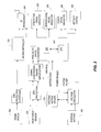
- Fig. 2 is a block diagram of a patient-feedback device for use in the spinal cord stimulation system of Fig. 1 .
- Fig. 3 is a partial cutaway view of a patient feedback device employing an isotonic force sensor.
- Fig. 4 is a perspective view of a patient feedback device employing an isometric force sensor.
- Fig. 5 is a perspective view of a patient feedback device employing a pressure sensor.
- Fig. 6 is a cross-sectional view of a patient feedback device employing strain gauge elements.
- Fig. 7 is a cross-sectional view of a patient feedback device employing strain gauge elements.
- Fig. 8 is a diagram of a half bridge circuit coupled to two strain gauge elements.
- Fig. 9 is a diagram of a full bridge circuit coupled to four strain gauge elements.
- Fig. 10 is a side view of a patient-feedback device inserted in the mouth of a patient.
- Fig. 11 is a side view of a patient-feedback device with optical sensing.
- Fig. 12 is a side view of a patient-feedback device activated by a foot of a patient.
- the invention herein relates to an electrical stimulation system for providing stimulation to a target tissue of a patient.
- the electrical stimulation system includes a patient-feedback device (PFD) 145.
- the PFD 145 is for use with a spinal cord stimulation (SCS) system 100, which provides electrical pulses to a patient, including to the neurons of the spinal cord and/or sacrum of a patient.
- SCS spinal cord stimulation
- Other electrical stimulation systems provide electrical pulses to other portions of a patient's body including a muscle or muscle group, peripheral nerves, the brain, etc.
- the PFD 145 is used in conjunction with a clinician programmer (CP) 130 to program an implantable pulse generator (IPG) 115 for a patient.
- the IPG 115 communicates with any one of the CP 130, a patient programmer and charger (PPC) 135, and a pocket (or fob) programmer (PP) 140.
- the CP 130 interacts with the IPG 115 to develop a program (or protocol) for stimulating the patient, which may be facilitated through the use of the PFD 145.
- the PPC 135 or the PP 140 can activate the protocol.
- the protocol may be stored at the IPG 115 or can be communicated and stored at the PPC 135 or the PP 140.
- the PPC 135 also is used for charging the IPG 115.
- Constructions of the IPG 115, CP 130, PPC 135, and PP 140 are disclosed in US Patent Application Nos. AA/AAA,AAA and BB/BBB,BBB, both of which are filed on even date herewith and are entitled "SYSTEM AND METHOD OF ESTABLISHING A PROTOCOL FOR PROVIDING ELECTRICAL STIMULATION WITH A STIMULATION SYSTEM TO TREAT A PATIENT", attorney docket nos. 029267-9002-00 and 029267-9002-01, respectively, and both of which are incorporated herein by reference.
- the PFD 145 is an ergonomic handheld device having a sensor (also referred to as input) 165, a controller, and a communications output 175.
- the sensor 165 can include a discrete switch and/or a continuously variable input, such as through the use of a thermocouple, strain gauge, pressure sensor, piezoelectric device, accelerometer, displacement mechanism, or other variable sensing mechanism. It is envisioned that the use of a continuously variable input can provide magnitude information, thereby providing improved feedback information from the patient.
- the CP 130 activates one or more of the electrodes of the IPG 115 in various patterns.
- a stimulus such as a stimulus for paresthesia
- he or she activates a sensor on the PFD 145.
- the activation of the sensor indicates to the system 100 that the patient 105 felt the stimulus and can also convey the degree of sensation that is felt, depending on the type of sensor that is employed.
- the system 100 then re-stimulates the most recently-activated combinations of electrodes and the patient 105 again uses the PFD 145 to indicate when (and to what degree) a sensation is felt in order to determine the combination of electrodes to which the patient 105 was reacting.
- Further description of methods for use of the IPG 115, CP 130, PPC 135, PP 140, and PFD 145 are disclosed in US Patent Application Nos. AA/AAA,AAA and BB/BBB,BBB, both of which were incorporated by reference above.
- Fig. 2 provides a block diagram of an exemplary handheld PFD 145 for use in the SCS system 100.
- the PFD 145 includes a housing 400 which may have one or more of a sensor, a controller, and/or a communication port connected thereto.
- the construction of the PFD 145 shown in Fig. 2 includes two inputs 200 and 205 in communication with the housing 400 of the device 145 and one input 210 internal to the housing 400.
- One of the external inputs 200 is a binary ON/OFF switch, preferably activated by the patient's thumb, to allow the patient 105 to immediately deactivate stimulation.
- Input 200 may be coupled to the controller 225 via electrostatic discharge (ESD) protection and/or debouncing circuits.
- ESD electrostatic discharge
- the second input 205 includes a force sensor sensing the pressure or force exerted by the patient's s hand.
- Input/sensor 205 may be coupled to the controller 225 via ESD protection, signal conditioning, and/or signal amplification circuits.
- the sensed parameter can be either isotonic (constant force, measuring the distance traversed) or isometric (measured force, proportional to pressure applied by patient 105).
- the resulting signal from the sensor 205 is analog and, therefore, after the signal is conditioned and/or amplified, it can be passed to microcontroller 225 via an analog-to-digital converter.
- the internal input 210 for the PFD 145 of Fig. 2 is a motion sensor.
- the sensor 210 upon detecting motion, initiates activation of the PFD 145.
- the device 145 stays active until movement is not detected by the sensor 210 for a time period, which in various constructions may be between one second and five minutes.
- Power is provided by an internal battery 220 that can be replaceable and/or rechargeable, which in various constructions has an approximately three hour life under continuous use.
- a motion sensor such as sensor 210 can also be used to obtain feedback from the patient 105 regarding paresthesia.
- microcontroller 225 The processing of the inputs from the sensors 200 and 205 takes place in a controller, such as a microcontroller 225.
- An exemplary microcontroller capable of being used with the invention is microcontroller 225, which includes a suitable programmable portion 230 (e.g., a microprocessor or a digital signal processor), a memory 235, and a bus 240 or other communication lines.
- Output data of the microcontroller 225 is sent via a Bluetooth bi-direction radio communication port 245 to the CP 130.
- the Bluetooth portion 245 includes a Bluetooth communication interface, an antenna switch, and a related antenna, all of which allows wireless communication following the Bluetooth Special Interest Group standard. Other forms of wired and wireless communication between the PFD 145 and other components of the system including the CP 130 are also possible.
- Other outputs may include indicators (such as light-emitting diodes) for communicating stimulation activity 250, sensor activation 255, device power 260, and battery status 265.
- the housing 400 of the PFD 145 may be cylindrical in shape ( Fig. 1 ), and in one particular construction the cylinder is approximately 35 mm in diameter and 80 mm in length. In other constructions the cylinder is larger or smaller in diameter and/or length, for example in order to accommodate hands of varying sizes. In various constructions the diameter can range from 20 to 50 mm and the length from 30 to 120 mm, although other sizes above and below these ranges are also possible.
- the shape of the PFD 145 can be other than a circular cross-section, for example oval, square, hexagonal, or other shape. Still further, the cross-section of the PFD 145 can vary along its length, for example being cylindrical in some portions and oval, square, hexagonal or other shape(s) in other portions. In yet other constructions, the PFD 145 has a spherical, toroid, or other shape.
- the housing 400 may be made from a resilient material such as rubber or plastic with one or more sensor 205 coupled to or supported by the housing 400.
- the manner in which the sensor 205 is coupled to the housing 400 depends on the type of sensor that is employed, as discussed below.
- the sensor 205 when the patient 105 applies a force to the housing 400, the sensor 205 generates a signal that generally is proportional to the degree of force applied.
- the discussion herein mentions the patient 105 using his or her hand to generate force to squeeze the housing 400 of the PFD 145, in various constructions the patient 105 may instead use other body parts, such as the mouth ( Fig. 10 ) or foot ( Fig. 12 ), to generate force.
- the patient can generate feedback by a physical action, usually a force applied by the hand or other body part, but the physical action can include other movements, such as movement of the patient's eyes ( Fig. 9 ), head, or hands, to generate a feedback signal.
- a physical action usually a force applied by the hand or other body part, but the physical action can include other movements, such as movement of the patient's eyes ( Fig. 9 ), head, or hands, to generate a feedback signal.
- the signal is generated, it is transmitted from the sensor 205 to the controller 225.
- the controller 225 processes the signal and, based on one or more such signals from the sensor 205, the controller 225 generates another signal that is to be transmitted to the CP 130.
- the controller 225 sends the signal to be transmitted to the communication port 245 of the PFD 145 from which it is then transmitted to the CP 130 or other external device.
- the signal can be transmitted from the communication port 245 to the CP 130 using various wired or wireless methods of communication.
- an isotonic force sensor may include a sensor that measures the distance traveled by the sensor with relatively constant force applied by the patient.
- Isotonic force sensors may include a trigger 310 ( Fig. 3 ) or other lever mechanism coupled to a wiper 320 that moves along a rheostat 330 or across a series of detectors.
- Exemplary detectors include electrical contacts or optical detectors, such as photodiodes.
- an isometric force sensor may include a strain gauge, a piezoelectric device, or a pressure sensor, each of which measures force that is proportional to the pressure applied to the PFD 145 by the patient, generally with only a small amount of travel or shape change to the sensor.
- Both the isotonic and isometric sensors generate an electrical signal that is proportional to the force that is applied to the sensor.
- An isometric force sensor may be incorporated into a relatively stiff object such that only slight deformation of the object is needed to register a change in force.
- the force sensor may include a combination of elements, such as a trigger or other lever that experiences increasing resistance or pressure as the travel distance increases. For example, increasing resistance or pressure can be created by attaching a relatively stiff spring to the lever or wiper mechanism to increase resistance as the lever or wiper is moved.
- the PFD 145 includes a feedback mechanism 460 that indicates to the patient 105 the amount of force that is detected by the force sensor 205.
- the feedback mechanism 460 may include one or more of a visual, audible, or tactile feedback mechanism that is used to indicate to the patient the degree to which the sensor 205 has been activated, e.g. how much force has been applied or how much the lever or wiper mechanism has traveled.
- the feedback mechanism gives the patient a sense of whether their activation of the sensor 205 is being detected at what the patient 105 feels is the correct level and to give the patient 105 a means to make their activation of the sensor 205 more consistent.
- Visual feedback mechanisms 460 can include a series of lights (e.g.
- audible feedback can include sounds that vary in amplitude (volume) and/or tone
- tactile feedback mechanisms can include vibration of the PFD 145 and/or altering the shape of the surface of the PFD 145 (e.g. raising of one or more structures such as dots to form Braille-type patterns) in a location that is capable of contacting the patient's skin.
- the feedback can include a semi-quantitative indication of the patient's response, e.g. including a variety (e.g.
- intensity levels to indicate a relative degree of force applied by the patient.
- the patient will then be able to see, hear, and/or feel the level of force that is sensed by the sensor 205 of the PFD 145, to help the patient 105 confirm that their response to the stimulus was received, as well as the degree of response that was registered.
- the correlation between the level of force applied and the output of the feedback device 460 can be calibrated separately for each patient 105 during an initial calibration session.
- the housing 400 may be covered with one or more surfaces, textures, or materials to improve grip, such as grooves, stipples, indentations, rubber, or plastic, and may include a wrist strap 470 to keep the PFD 145 from falling if it is dropped by the patient.
- the PFD 145 may also include a connection feedback mechanism, particularly where the PFD 145 is in wireless communication with the CP 130.
- the connection feedback mechanism can include one or more of a visual, audible, or tactile mechanism to inform the patient and/or medical personnel of whether the PFD 145 is maintaining a connection with the CP 130, the strength of the connection, and/or if the connection has been lost.
- the PFD 145 may emit a signal (e.g. light, sound, and/or tactile) at regular (e.g. one minute) intervals to confirm that communication is still maintained. Conversely, the PFD 145 may emit such a signal only if communication is lost.
- the PFD 145 may tolerate brief intervals in which the signal is lost (e.g. a predetermined time, generally between 0.1-100 sec) before the patient is warned of a possible lost connection.
- the controller 225 of the PFD 145 includes memory that permits buffering of a limited amount of data, which can be used to accumulate data prior to sending to the CP 130 and which can hold data during brief intervals in which the connection is lost.
- the CP 130 stops stimulation of electrodes until a connection with the PFD 145 is reestablished.
- the PFD 145 may include one or more of: a sound generating mechanism 420 (e.g. a speaker); a tactile mechanism 430 such as a vibration device and/or a mechanism for creating a raised pattern; a digital numerical readout 440 (e.g. LED or LCD display); and one or more indicator lights 450 (e.g. a series of LEDs); which may be employed to provide feedback to the patient 105 regarding the force being applied and/or communication status.
- a sound generating mechanism 420 e.g. a speaker
- a tactile mechanism 430 such as a vibration device and/or a mechanism for creating a raised pattern
- a digital numerical readout 440 e.g. LED or LCD display
- indicator lights 450 e.g. a series of LEDs
- sensing mechanisms can be used for the sensor 205, which would depend in part on the type of housing 400 that is used with the PFD 145.
- the housing 400 is a sealed, flexible compartment (e.g. a ball or other object filled with gel, air, or liquid)
- a piezoelectric-based pressure sensing mechanism can be used as the sensor 205 in order to measure changes in pressure when the patient squeezes or relaxes his/her grip on the PFD 145.
- a rheostat 330 or other linear sensing mechanism can be used with a pistol grip style PFD 145 design ( Fig. 3 ), where a trigger 310 is coupled to a wiper 320 that moves across the rheostat 330 or other linear sensor.
- a strain gauge sensor can be used with a housing 400 that is sufficiently resilient to permit the housing to be deformed so as to activate the strain gauge.
- the strain gauge elements 480 e.g. two elements for use with a half-bridge circuit and four elements for use with a full-bridge circuit
- the elements can be connected to the housing 400 in several different ways.
- the elements can be mounted directly to the housing 400, for example on opposing inside flat faces of the housing of the PFD 145, in which case the patient is instructed to squeeze the flat faces towards one another.
- the strain gauge elements can be mounted to opposite faces of a flexible element 490.
- the flexible element 490 may be a rectangular strip that is mounted across the inside, for example in a circular shape for mounting inside a cylindrical housing 400.
- the flexible element 490 can be mounted inside the housing 400 perpendicular to the outer surface such that applying a force across any opposing sides of the PFD 145 causes the flexible element 490 to flex and thus trigger the strain gauge elements 480.
- This latter design would remove the requirement for the housing 400 to have opposing flattened faces that the patient would have to squeeze together.
- two strain gauge elements 480 can be coupled to a half-bridge circuit 500 ( Fig. 8 ), where the use of two elements 480 has the advantage of increasing the signal response as well as canceling out temperature variations in the PFD 145.
- four strain gauge elements 480 can be coupled to a full-bridge circuit 510 ( Fig. 9 ).
- the two strain gauge elements 480 can be placed on the inside walls of the housing 400 or can be placed on opposite sites of a flexible element 490 that is mounted inside the housing 400 in a manner that causes the flexible element 490 to bend when a force is applied to the housing 400.
- the flexible element 490 may be various shapes (e.g. elongated or circular) and more than one flexible element 490 may be mounted inside the housing 400 to enhance the responsiveness of the PFD 145 to applied forces.
- Figs. 10-12 provide other means for receiving patient feedback. More specifically, Fig. 10 shows a mouth-piece 520 that is inserted into the mouth of the patient. The user provides feedback by biting the mouthpiece. Fig. 11 shows an optical sensor 530 (such as a camera and related image processing software) that detects visual cues from a patient. An example visual cue may be the blinking of the patient's eyes. Fig. 12 shows a foot pedal 540 that receives input through the patient's 105 manipulation of a switch and/or sensor with his foot.
- an optical sensor 530 such as a camera and related image processing software
- the PFD 145 includes one or more accelerometer (such as the motion sensor 210) and the patient 105 provides feedback by moving the PFD 145 in various distinct patterns that are recognized by the controller 225 of the PFD 145 or by the CP 130. It is also envisioned that the patient may provide feedback directly to the CP 130.
- the patient 105 is trained to use the particular feedback device (e.g. the PFD 145 or the CP 130 as applicable) in order to properly inform the CP 130 of the patient's reaction to stimuli as they are applied to the IPG 115 in the patient 130.
- the CP 130 is programmed to learn the patient's response times and/or the magnitude of the patient's responses in order to obtain a profile of the patient's reaction to various stimuli, as discussed above.
- the PFD 145 may include a clock (e.g. as part of controller 225) that is synchronized with a clock in CP 130 so that as the patient 105 operates the PFD 145, each action recorded by the PFD 145 has a time associated therewith.
- a clock e.g. as part of controller 225
- each action recorded by the PFD 145 has a time associated therewith.
- the PFD 145 can work without calibration in a relative or binary way.
- the system 100 includes procedures for calibrating the patient's response time and/or for 'learning' the patient's response time during ongoing use of the system 100.
- the discussion is presented in terms of the patient applying pressure or force, e.g. with his or her hand, the calibration or learning procedures discussed herein can be applied to other physical actions taken by a patient in response to a signal or stimulus, e.g. movements of the patient's head, eyes, or hands.
- Steps of such a calibration procedure for a patient include: at a first time, applying a stimulus to the IPG 115 in the patient; monitoring the sensor 205 of the PFD 145 at a plurality of time points; recording a level of the force sensed by the sensor 205 at each of the plurality of time points; identifying at least one of a time point at which a maximum force is applied and a time point at which a minimum force is applied; comparing the first time to at least one of the time point at which a minimum force is applied and the time point at which a maximum force is applied to determine a patient response time; and recording the patient response time in a memory.
- Analyzing the data generally includes identifying a local minimum or maximum of force, which can be done several ways.
- One method is to calculate the first derivative (dF/dt) of the force measurements over time to identify the time points at which force is applied (local maximum) and removed (local minimum).
- Another method is to apply a high-pass filter to the force vs. time data to identify local maxima and minima.
- Still another method employs a learning algorithm to identify probabilities of maxima and minima based on the patient's use of the PFD 145. For example, after the patient 105 has squeezed the PFD 145 a number of times in response to electrode stimulation events and the system 100 has identified which stimulation event the patient was responding to, the system 100 can calculate an average lag time from the initial stimulation event to the patient's response thereto.
- the patient 105 provides feedback to the SCS system 100, and specifically the CP 130, while the CP 130 establishes the protocol for the IPG 115.
- the patient 105 can activate the PFD 145 when the patient 105 feels various stimuli, such as pain (or paresthesia).
- the invention provides a useful and novel system and method of providing patient feedback to a programming device of an electrical stimulation system.
Landscapes
- Health & Medical Sciences (AREA)
- Nuclear Medicine, Radiotherapy & Molecular Imaging (AREA)
- Neurology (AREA)
- Neurosurgery (AREA)
- Engineering & Computer Science (AREA)
- Biomedical Technology (AREA)
- Radiology & Medical Imaging (AREA)
- Life Sciences & Earth Sciences (AREA)
- Animal Behavior & Ethology (AREA)
- General Health & Medical Sciences (AREA)
- Public Health (AREA)
- Veterinary Medicine (AREA)
- Pain & Pain Management (AREA)
- Electrotherapy Devices (AREA)
Abstract
Description
- The invention relates to a patient handheld device for a stimulation system, such as a spinal cord stimulation (SCS) system, and in particular to a handheld device that a patient can use to provide feedback during programming of an electrical stimulation generator, such as an implantable pulse generator (IPG).
- A spinal cord stimulator is a device used to provide electrical stimulation to the spinal cord or spinal nerve neurons for managing pain. The stimulator includes an implanted or external pulse generator and an implanted medical electrical lead having one or more electrodes at a distal location thereof. The pulse generator provides the stimulation through the electrodes via a body portion and connector of the lead. Spinal cord stimulation programming is defined as the discovery of the stimulation electrodes and parameters that provide the best possible pain relief (or paresthesia) for the patient using one or more implanted leads and its attached IPG. The programming is typically achieved by selecting individual electrodes and adjusting the stimulation parameters, such as the shape of the stimulation waveform, amplitude of current in mA (or amplitude of voltage in V), pulse width in microseconds, frequency in Hz, and anodic or cathodic stimulation.
- With newer medical electrical leads having an increased number of electrodes, the electrode and parameter combination increases exponentially. This results in a healthcare professional, such as a clinician, requiring a substantial amount of time for establishing a manually created protocol for providing therapeutic spinal cord stimulation. Therefore, a manual approach for creating a protocol is not an optimal solution for the SCS system.
- Numerous embodiments of the invention provide a method and system for programming an SCS system with a substantially reduced time requirement and increased accuracy. More specifically, in numerous embodiments, a sweep process is used with the electrodes of an implanted medical lead to determine the proper SCS program (also referred to herein as an SCS protocol) for providing the best possible pain relief for the patient. In other embodiments, a sweep process can be used on a single electrode by varying a pulse width, frequency, or amplitude applied to the single electrode, for example. It is also envisioned that other sweep processes are possible, such as combinations of the above sweep processes.
- Thus, in one aspect the invention provides a patient feedback device for communicating with a programming device of an electrical stimulation system. The device includes a housing, a sensor, a controller, and a communication port. The sensor is supported by the housing and generates a sensor signal in response to an action from the patient. The controller is supported by the housing and is in operative communication with the sensor. The controller receives the sensor signal and sends information to the communication port based on the sensor signal. The communication port is connected to the housing and is in operative communication with the controller. The communication port receives information from the controller and wirelessly transmits a communication signal to the programming device of the electrical stimulation system.
- In another aspect the invention provides a method of providing patient feedback to a programming device of an electrical stimulation system with a patient feedback device, where the patient feedback device includes a housing having a sensor, a controller, and a communication port connected thereto and the controller is in operative communication with the sensor and the communication port. The sensor detects a force, a distance traveled, or other impetus applied by the patient in response to a stimulus received by the patient. The sensor generates a signal in response to the applied impetus. The controller receives the signal generated by the sensor. The controller sends information to the communication port based on the signal. The communication port transmits a signal to the programming device.
- In still another aspect the invention provides a patient feedback device for communicating with a programming device of an electrical stimulation system. The device includes a resilient housing, a sensor, a controller, and a communication port. The sensor is supported by the housing and generates a sensor signal in response to an impetus applied to the housing by the patient. The controller is supported by the housing and is in operative communication with the sensor. The controller receives the sensor signal and sends information to the communication port based on the sensor signal. The communication port is connected to the housing and is in operative communication with the controller. The communication port receives information from the controller and transmits a communication signal to the programming device of the electrical stimulation system.
- In yet another aspect the invention provides a method of calibrating a patient feedback device for use in an electrical stimulation system, where the system includes an implantable pulse generator (IPG) implanted in a patient and a patient feedback device having a force sensor. The method includes steps of: sensing input from the patient using the patient feedback device; at a first time, applying an electrical stimulus with the IPG; monitoring the force sensor at a plurality of time points; recording a level of force sensed by the force sensor at each of the plurality of time points; identifying at least one of a time point at which a maximum force is applied and a time point at which a minimum force is applied; and comparing the first time to at least one of the time point at which a minimum force is applied and the time point at which a maximum force is applied to determine a patient response time.
- Further, the present invention may also be directed to the subject-matter of one of the following sections. The features of these sections and all features of the present description may be combined with one another.
- 1. A patient feedback device for communicating with a programming device of an electrical stimulation system, the feedback device comprising:
- a housing;
- a sensor supported by the housing, the sensor generating a sensor signal in response to an action from the patient;
- a controller supported by the housing and in operative communication with the sensor, the controller receiving the sensor signal and sending information to the communication port based on the sensor signal; and
- a communication port connected to the housing and in operative communication with the controller, the communication port receiving information from the controller and wirelessly transmitting a communication signal to the programming device of the electrical stimulation system.
- 2. The patient feedback system according to
section 1, wherein the housing is resilient and the sensor generates the sensor signal in response to force applied to the housing. - 3. The patient feedback system according to
section 1 or 2, wherein the sensor comprises a strain gauge. - 4. The patient feedback system according to one of the preceding sections, wherein the housing includes a force feedback mechanism that indicates the level of force applied to the housing.
- 5. The patient feedback system according to section 4, wherein the force feedback mechanism includes one or more of: a plurality of lights; a digital display; an audio output; and a tactile output.
- 6. The patient feedback system according to one of the preceding sections, wherein the housing includes a connection feedback mechanism that indicates the status of the connection between the communication port and the programming device.
- 7. The patient feedback system according to section 6, wherein the connection feedback mechanism includes one or more of: a plurality of lights; a digital display; an audio output; and a tactile output.
- 8. The patient feedback system according to one of the preceding sections, wherein the controller further comprises a controller clock and wherein the controller clock is synchronized with a clock in the programming device.
- 9. A method of providing patient feedback to a programming device of an electrical stimulation system with a patient feedback device, the patient feedback device including a housing having a sensor, a controller, and a communication port connected thereto, wherein the controller is in operative communication with the sensor and the communication port, the method comprising:
- the sensor receiving an impetus applied by the patient in response to a stimulus received by the patient;
- the sensor generating a signal in response to the applied impetus;
- the controller receiving the signal generated by the sensor;
- the controller sending information to the communication port based on the signal; and
- the communication port transmitting a signal to the programming device.
- 10. The method of providing patient feedback according to section 9, wherein the housing is resilient and the method further comprises generating the sensor signal in response to a force applied to the housing.
- 11. The method of providing patient feedback according to section 9 or 10, wherein the step of the sensor generating a signal in response to the applied force further comprises the sensor generating a signal in response to the applied force using a strain gauge.
- 12. The method of providing patient feedback according to one of sections 9 to 11, wherein the housing includes a force feedback mechanism and the method further comprises indicating, using the force feedback mechanism, the level of force applied to the housing.
- 13. The method of providing patient feedback according to section 12, wherein the step of indicating, using the force feedback mechanism, the level of force applied to the housing comprises indicating the level of force applied to the housing using one or more of: a plurality of lights; a digital display; an audio output; and a tactile output.
- 14. The method of providing patient feedback according to one of sections 9 to 13, wherein the housing includes a connection feedback mechanism and the method further includes indicating, using the connection feedback mechanism, the status of the connection between the communication port and the programming device.
- 15. The method of providing patient feedback according to section 14, wherein indicating, using the connection feedback mechanism, the status of the connection between the communication port and the programming device comprises indicating the status of the connection between the communication port and the programming device using one or more of: a plurality of lights; a digital display; an audio output; and a tactile output.
- 16. The patient feedback system or method according to one of sections 9 to 15, wherein the controller further comprises a controller clock synchronized with a clock in the programming device, the controller receiving the signal generated by the sensor further comprising recording a time on the controller clock.
- 17. The patient feedback system or method according to one of sections 9 to 16, wherein the step of the communication port transmitting a signal to the programming device comprises the communication port transmitting a signal to the programming device using wireless communication.
- 18. A patient feedback device for communicating with a programming device of an electrical stimulation system, the feedback device comprising:
- a resilient housing;
- a sensor supported by the housing, the sensor generating a sensor signal in response to an impetus applied to the housing by the patient;
- a controller supported by the housing and in operative communication with the sensor, the controller receiving the sensor signal and sending information to the communication port based on the sensor signal; and
- a communication port connected to the housing and in operative communication with the controller, the communication port receiving information from the controller and transmitting a communication signal to the programming device of the electrical stimulation system.
- 19. The patient feedback system according to section 18, wherein the sensor comprises a strain gauge.
- 20. The patient feedback system according to one of sections 18 or 19, wherein the housing includes a force feedback mechanism that indicates the level of force applied to the housing.
- 21. The patient feedback system according to section 20, wherein the force feedback mechanism includes one or more of: a plurality of lights; a digital display; an audio output; and a tactile output.
- 22. The patient feedback system according to one of sections 18 to 21, wherein the communication port transmits the communication signal to the programming device using a wireless signal.
- 23. The patient feedback system according to one of sections 18 to 22, wherein the housing includes a connection feedback mechanism that indicates the status of the connection between the communication port and the programming device.
- 24. The patient feedback system according to section 23, wherein the connection feedback mechanism includes one or more of: a plurality of lights; a digital display; an audio output; and a tactile output.
- 25. The patient feedback system according to one of sections 18 to 24, wherein the controller further comprises a controller clock and wherein the controller clock is synchronized with a clock in the programming device.
- 26. A method of calibrating a patient feedback device for use in an electrical stimulation system, the system including an implantable pulse generator (IPG) implanted in a patient and a patient feedback device having a force sensor, the method comprising:
- sensing input from the patient using the patient feedback device;
- at a first time, applying an electrical stimulus with the IPG;
- monitoring the force sensor at a plurality of time points;
- recording a level of force sensed by the force sensor at each of the plurality of time points;
- identifying at least one of a time point at which a maximum force is applied and a time point at which a minimum force is applied; and
- comparing the first time to at least one of the time point at which a minimum force is applied and the time point at which a maximum force is applied to determine a patient response time.
- 27. The method of calibrating a patient feedback device according to section 26, wherein identifying at least one of a time point at which a maximum force is applied and a time point at which a minimum force is applied comprises calculating a first derivative of the levels of force sensed by the force sensor at each of the plurality of time points.
- 28. The method of calibrating a patient feedback device according to section 26 or 27, wherein identifying at least one of a time point at which a maximum force is applied and a time point at which a minimum force is applied comprises applying a high-pass filter to the levels of force sensed by the force sensor at each of the plurality of time points.
- 29. The method of calibrating a patient feedback device according to one of sections 26 to 28, wherein identifying at least one of a time point at which a maximum force is applied and a time point at which a minimum force is applied comprises using a learning algorithm to identify probabilities of maxima and minima based on the patient's use of the patient feedback device.
- Other aspects of the invention will become apparent by consideration of the detailed description and accompanying drawings.
-
Fig. 1 is a partial perspective view of a patient using a spinal cord stimulation system. -
Fig. 2 is a block diagram of a patient-feedback device for use in the spinal cord stimulation system ofFig. 1 . -
Fig. 3 is a partial cutaway view of a patient feedback device employing an isotonic force sensor. -
Fig. 4 is a perspective view of a patient feedback device employing an isometric force sensor. -
Fig. 5 is a perspective view of a patient feedback device employing a pressure sensor. -
Fig. 6 is a cross-sectional view of a patient feedback device employing strain gauge elements. -
Fig. 7 is a cross-sectional view of a patient feedback device employing strain gauge elements. -
Fig. 8 is a diagram of a half bridge circuit coupled to two strain gauge elements. -
Fig. 9 is a diagram of a full bridge circuit coupled to four strain gauge elements. -
Fig. 10 is a side view of a patient-feedback device inserted in the mouth of a patient. -
Fig. 11 is a side view of a patient-feedback device with optical sensing. -
Fig. 12 is a side view of a patient-feedback device activated by a foot of a patient. - Before any embodiments of the invention are explained in detail, it is to be understood that the invention is not limited in its application to the details of construction and the arrangement of components set forth in the following description or illustrated in the following drawings. The invention is capable of other constructions and of being practiced or of being carried out in various ways.
- The invention herein relates to an electrical stimulation system for providing stimulation to a target tissue of a patient. The electrical stimulation system includes a patient-feedback device (PFD) 145. In the construction shown, the
PFD 145 is for use with a spinal cord stimulation (SCS)system 100, which provides electrical pulses to a patient, including to the neurons of the spinal cord and/or sacrum of a patient. Other electrical stimulation systems provide electrical pulses to other portions of a patient's body including a muscle or muscle group, peripheral nerves, the brain, etc. - In various implementations, the
PFD 145 is used in conjunction with a clinician programmer (CP) 130 to program an implantable pulse generator (IPG) 115 for a patient. TheIPG 115 communicates with any one of theCP 130, a patient programmer and charger (PPC) 135, and a pocket (or fob) programmer (PP) 140. As discussed in further detail below, theCP 130 interacts with theIPG 115 to develop a program (or protocol) for stimulating the patient, which may be facilitated through the use of thePFD 145. Once a protocol is developed by the CP, thePPC 135 or thePP 140 can activate the protocol. The protocol may be stored at theIPG 115 or can be communicated and stored at thePPC 135 or thePP 140. ThePPC 135 also is used for charging theIPG 115. Constructions of theIPG 115,CP 130,PPC 135, andPP 140 are disclosed in US Patent Application Nos. AA/AAA,AAA and BB/BBB,BBB, both of which are filed on even date herewith and are entitled "SYSTEM AND METHOD OF ESTABLISHING A PROTOCOL FOR PROVIDING ELECTRICAL STIMULATION WITH A STIMULATION SYSTEM TO TREAT A PATIENT", attorney docket nos. 029267-9002-00 and 029267-9002-01, respectively, and both of which are incorporated herein by reference. - Referring back to
Fig. 1 , a user may provide feedback to theCP 130 with thePFD 145 while theCP 130 develops the protocol for theIPG 115. In the construction shown inFig. 1 , thePFD 145 is an ergonomic handheld device having a sensor (also referred to as input) 165, a controller, and a communications output 175. Thesensor 165 can include a discrete switch and/or a continuously variable input, such as through the use of a thermocouple, strain gauge, pressure sensor, piezoelectric device, accelerometer, displacement mechanism, or other variable sensing mechanism. It is envisioned that the use of a continuously variable input can provide magnitude information, thereby providing improved feedback information from the patient. - In use, the
CP 130 activates one or more of the electrodes of theIPG 115 in various patterns. When thepatient 105 feels a sensation as a result of a stimulus, such as a stimulus for paresthesia, he or she activates a sensor on thePFD 145. The activation of the sensor indicates to thesystem 100 that thepatient 105 felt the stimulus and can also convey the degree of sensation that is felt, depending on the type of sensor that is employed. Given that there may be a delay from the time thepatient 105 feels a sensation and activates the sensor, thesystem 100 then re-stimulates the most recently-activated combinations of electrodes and thepatient 105 again uses thePFD 145 to indicate when (and to what degree) a sensation is felt in order to determine the combination of electrodes to which thepatient 105 was reacting. Further description of methods for use of theIPG 115,CP 130,PPC 135,PP 140, andPFD 145 are disclosed in US Patent Application Nos. AA/AAA,AAA and BB/BBB,BBB, both of which were incorporated by reference above. -
Fig. 2 provides a block diagram of anexemplary handheld PFD 145 for use in theSCS system 100. In various constructions, thePFD 145 includes ahousing 400 which may have one or more of a sensor, a controller, and/or a communication port connected thereto. The construction of thePFD 145 shown inFig. 2 includes twoinputs housing 400 of thedevice 145 and oneinput 210 internal to thehousing 400. One of theexternal inputs 200 is a binary ON/OFF switch, preferably activated by the patient's thumb, to allow thepatient 105 to immediately deactivate stimulation. Input 200 may be coupled to thecontroller 225 via electrostatic discharge (ESD) protection and/or debouncing circuits. Thesecond input 205 includes a force sensor sensing the pressure or force exerted by the patient's s hand. Input/sensor 205 may be coupled to thecontroller 225 via ESD protection, signal conditioning, and/or signal amplification circuits. The sensed parameter can be either isotonic (constant force, measuring the distance traversed) or isometric (measured force, proportional to pressure applied by patient 105). The resulting signal from thesensor 205 is analog and, therefore, after the signal is conditioned and/or amplified, it can be passed tomicrocontroller 225 via an analog-to-digital converter. - The
internal input 210 for thePFD 145 ofFig. 2 is a motion sensor. Thesensor 210, upon detecting motion, initiates activation of thePFD 145. Thedevice 145 stays active until movement is not detected by thesensor 210 for a time period, which in various constructions may be between one second and five minutes. Power is provided by aninternal battery 220 that can be replaceable and/or rechargeable, which in various constructions has an approximately three hour life under continuous use. As discussed below, a motion sensor such assensor 210 can also be used to obtain feedback from thepatient 105 regarding paresthesia. - The processing of the inputs from the
sensors microcontroller 225. An exemplary microcontroller capable of being used with the invention ismicrocontroller 225, which includes a suitable programmable portion 230 (e.g., a microprocessor or a digital signal processor), amemory 235, and abus 240 or other communication lines. Output data of themicrocontroller 225 is sent via a Bluetooth bi-directionradio communication port 245 to theCP 130. TheBluetooth portion 245 includes a Bluetooth communication interface, an antenna switch, and a related antenna, all of which allows wireless communication following the Bluetooth Special Interest Group standard. Other forms of wired and wireless communication between thePFD 145 and other components of the system including theCP 130 are also possible. Other outputs may include indicators (such as light-emitting diodes) for communicatingstimulation activity 250,sensor activation 255,device power 260, andbattery status 265. - The
housing 400 of thePFD 145 may be cylindrical in shape (Fig. 1 ), and in one particular construction the cylinder is approximately 35 mm in diameter and 80 mm in length. In other constructions the cylinder is larger or smaller in diameter and/or length, for example in order to accommodate hands of varying sizes. In various constructions the diameter can range from 20 to 50 mm and the length from 30 to 120 mm, although other sizes above and below these ranges are also possible. - Furthermore, the shape of the
PFD 145 can be other than a circular cross-section, for example oval, square, hexagonal, or other shape. Still further, the cross-section of thePFD 145 can vary along its length, for example being cylindrical in some portions and oval, square, hexagonal or other shape(s) in other portions. In yet other constructions, thePFD 145 has a spherical, toroid, or other shape. - The
housing 400 may be made from a resilient material such as rubber or plastic with one ormore sensor 205 coupled to or supported by thehousing 400. The manner in which thesensor 205 is coupled to thehousing 400 depends on the type of sensor that is employed, as discussed below. Thus, when thepatient 105 applies a force to thehousing 400, thesensor 205 generates a signal that generally is proportional to the degree of force applied. Although the discussion herein mentions thepatient 105 using his or her hand to generate force to squeeze thehousing 400 of thePFD 145, in various constructions thepatient 105 may instead use other body parts, such as the mouth (Fig. 10 ) or foot (Fig. 12 ), to generate force. More generally, the patient can generate feedback by a physical action, usually a force applied by the hand or other body part, but the physical action can include other movements, such as movement of the patient's eyes (Fig. 9 ), head, or hands, to generate a feedback signal. After the signal is generated, it is transmitted from thesensor 205 to thecontroller 225. Thecontroller 225 processes the signal and, based on one or more such signals from thesensor 205, thecontroller 225 generates another signal that is to be transmitted to theCP 130. Thecontroller 225 sends the signal to be transmitted to thecommunication port 245 of thePFD 145 from which it is then transmitted to theCP 130 or other external device. As discussed further below, the signal can be transmitted from thecommunication port 245 to theCP 130 using various wired or wireless methods of communication. - In various constructions, an isotonic force sensor may include a sensor that measures the distance traveled by the sensor with relatively constant force applied by the patient. Isotonic force sensors may include a trigger 310 (
Fig. 3 ) or other lever mechanism coupled to awiper 320 that moves along arheostat 330 or across a series of detectors. Exemplary detectors include electrical contacts or optical detectors, such as photodiodes. In other constructions, an isometric force sensor may include a strain gauge, a piezoelectric device, or a pressure sensor, each of which measures force that is proportional to the pressure applied to thePFD 145 by the patient, generally with only a small amount of travel or shape change to the sensor. Both the isotonic and isometric sensors generate an electrical signal that is proportional to the force that is applied to the sensor. An isometric force sensor may be incorporated into a relatively stiff object such that only slight deformation of the object is needed to register a change in force. In still other constructions, the force sensor may include a combination of elements, such as a trigger or other lever that experiences increasing resistance or pressure as the travel distance increases. For example, increasing resistance or pressure can be created by attaching a relatively stiff spring to the lever or wiper mechanism to increase resistance as the lever or wiper is moved. - In some constructions (e.g. as shown in
Fig. 4 ), thePFD 145 includes afeedback mechanism 460 that indicates to thepatient 105 the amount of force that is detected by theforce sensor 205. Thefeedback mechanism 460 may include one or more of a visual, audible, or tactile feedback mechanism that is used to indicate to the patient the degree to which thesensor 205 has been activated, e.g. how much force has been applied or how much the lever or wiper mechanism has traveled. The feedback mechanism gives the patient a sense of whether their activation of thesensor 205 is being detected at what thepatient 105 feels is the correct level and to give the patient 105 a means to make their activation of thesensor 205 more consistent.Visual feedback mechanisms 460 can include a series of lights (e.g. LEDs) or a digital readout (e.g. a numerical display); audible feedback can include sounds that vary in amplitude (volume) and/or tone; and tactile feedback mechanisms can include vibration of thePFD 145 and/or altering the shape of the surface of the PFD 145 (e.g. raising of one or more structures such as dots to form Braille-type patterns) in a location that is capable of contacting the patient's skin. Using a combination of feedback modalities will benefit patients who have sensory impairments, including, e.g., impaired hearing and/or sight. The feedback can include a semi-quantitative indication of the patient's response, e.g. including a variety (e.g. 1-5 or 1-10) intensity levels to indicate a relative degree of force applied by the patient. The patient will then be able to see, hear, and/or feel the level of force that is sensed by thesensor 205 of thePFD 145, to help thepatient 105 confirm that their response to the stimulus was received, as well as the degree of response that was registered. The correlation between the level of force applied and the output of thefeedback device 460 can be calibrated separately for each patient 105 during an initial calibration session. - To facilitate gripping of the
PFD 145, thehousing 400, in certain constructions, may be covered with one or more surfaces, textures, or materials to improve grip, such as grooves, stipples, indentations, rubber, or plastic, and may include awrist strap 470 to keep thePFD 145 from falling if it is dropped by the patient. - The
PFD 145, in some constructions, may also include a connection feedback mechanism, particularly where thePFD 145 is in wireless communication with theCP 130. The connection feedback mechanism can include one or more of a visual, audible, or tactile mechanism to inform the patient and/or medical personnel of whether thePFD 145 is maintaining a connection with theCP 130, the strength of the connection, and/or if the connection has been lost. For example, thePFD 145 may emit a signal (e.g. light, sound, and/or tactile) at regular (e.g. one minute) intervals to confirm that communication is still maintained. Conversely, thePFD 145 may emit such a signal only if communication is lost. In some constructions, thePFD 145 may tolerate brief intervals in which the signal is lost (e.g. a predetermined time, generally between 0.1-100 sec) before the patient is warned of a possible lost connection. In various constructions, thecontroller 225 of thePFD 145 includes memory that permits buffering of a limited amount of data, which can be used to accumulate data prior to sending to theCP 130 and which can hold data during brief intervals in which the connection is lost. In various constructions, if communication between thePFD 145 and theCP 130 is lost for more than a predetermined interval of time, then theCP 130 stops stimulation of electrodes until a connection with thePFD 145 is reestablished. - Thus, according to various constructions, the
PFD 145 may include one or more of: a sound generating mechanism 420 (e.g. a speaker); atactile mechanism 430 such as a vibration device and/or a mechanism for creating a raised pattern; a digital numerical readout 440 (e.g. LED or LCD display); and one or more indicator lights 450 (e.g. a series of LEDs); which may be employed to provide feedback to thepatient 105 regarding the force being applied and/or communication status. - Various types of sensing mechanisms can be used for the
sensor 205, which would depend in part on the type ofhousing 400 that is used with thePFD 145. For example, if thehousing 400 is a sealed, flexible compartment (e.g. a ball or other object filled with gel, air, or liquid) a piezoelectric-based pressure sensing mechanism can be used as thesensor 205 in order to measure changes in pressure when the patient squeezes or relaxes his/her grip on thePFD 145. Alternatively, arheostat 330 or other linear sensing mechanism can be used with a pistolgrip style PFD 145 design (Fig. 3 ), where atrigger 310 is coupled to awiper 320 that moves across therheostat 330 or other linear sensor. - In another alternative shown in
Figs. 6 and 7 , a strain gauge sensor can be used with ahousing 400 that is sufficiently resilient to permit the housing to be deformed so as to activate the strain gauge. The strain gauge elements 480 (e.g. two elements for use with a half-bridge circuit and four elements for use with a full-bridge circuit) can be connected to thehousing 400 in several different ways. The elements can be mounted directly to thehousing 400, for example on opposing inside flat faces of the housing of thePFD 145, in which case the patient is instructed to squeeze the flat faces towards one another. Alternatively, the strain gauge elements can be mounted to opposite faces of aflexible element 490. Theflexible element 490 may be a rectangular strip that is mounted across the inside, for example in a circular shape for mounting inside acylindrical housing 400. In this particular construction, theflexible element 490 can be mounted inside thehousing 400 perpendicular to the outer surface such that applying a force across any opposing sides of thePFD 145 causes theflexible element 490 to flex and thus trigger thestrain gauge elements 480. This latter design would remove the requirement for thehousing 400 to have opposing flattened faces that the patient would have to squeeze together. - In various constructions, two
strain gauge elements 480 can be coupled to a half-bridge circuit 500 (Fig. 8 ), where the use of twoelements 480 has the advantage of increasing the signal response as well as canceling out temperature variations in thePFD 145. Alternatively, fourstrain gauge elements 480 can be coupled to a full-bridge circuit 510 (Fig. 9 ). As discussed above, the twostrain gauge elements 480 can be placed on the inside walls of thehousing 400 or can be placed on opposite sites of aflexible element 490 that is mounted inside thehousing 400 in a manner that causes theflexible element 490 to bend when a force is applied to thehousing 400. Theflexible element 490 may be various shapes (e.g. elongated or circular) and more than oneflexible element 490 may be mounted inside thehousing 400 to enhance the responsiveness of thePFD 145 to applied forces. -
Figs. 10-12 provide other means for receiving patient feedback. More specifically,Fig. 10 shows a mouth-piece 520 that is inserted into the mouth of the patient. The user provides feedback by biting the mouthpiece.Fig. 11 shows an optical sensor 530 (such as a camera and related image processing software) that detects visual cues from a patient. An example visual cue may be the blinking of the patient's eyes.Fig. 12 shows afoot pedal 540 that receives input through the patient's 105 manipulation of a switch and/or sensor with his foot. In other constructions thePFD 145 includes one or more accelerometer (such as the motion sensor 210) and thepatient 105 provides feedback by moving thePFD 145 in various distinct patterns that are recognized by thecontroller 225 of thePFD 145 or by theCP 130. It is also envisioned that the patient may provide feedback directly to theCP 130. In various constructions, thepatient 105 is trained to use the particular feedback device (e.g. thePFD 145 or theCP 130 as applicable) in order to properly inform theCP 130 of the patient's reaction to stimuli as they are applied to theIPG 115 in thepatient 130. In particular constructions, theCP 130 is programmed to learn the patient's response times and/or the magnitude of the patient's responses in order to obtain a profile of the patient's reaction to various stimuli, as discussed above. - In some constructions the
PFD 145 may include a clock (e.g. as part of controller 225) that is synchronized with a clock inCP 130 so that as thepatient 105 operates thePFD 145, each action recorded by thePFD 145 has a time associated therewith. Thus, even if there is a delay in transmitting information from thePFD 145 to the CP 130 (e.g. due to communication problems) there will nevertheless be an indication of when each action (e.g. squeezing of thePFD 145 leading to activation of the sensor 205) was recorded, which will enable theCP 130 to determine which of the most recent electrical stimuli likely led to the patient's response. - In some constructions, the
PFD 145 can work without calibration in a relative or binary way. However, to facilitate identification of which of the stimuli thepatient 105 has reacted to when using thePFD 145, thesystem 100, in some other constructions, includes procedures for calibrating the patient's response time and/or for 'learning' the patient's response time during ongoing use of thesystem 100. In one construction, thesystem 100 includes a calibration procedure in which the patient receives a signal or stimulus to apply pressure to thePFD 145 at time t=0. The actual times that the patient applies and releases pressure (e.g. squeezes thePFD 145 with his or her hand or other body portion) can then be compared and the difference between the signal time at t=0 and the time pressure is applied and released on thePFD 145 are indicators of the patient's response lag time. Knowing the lag time facilitates determining which particular electrical stimulus thepatient 105 has responded to via thePFD 145. Although the discussion is presented in terms of the patient applying pressure or force, e.g. with his or her hand, the calibration or learning procedures discussed herein can be applied to other physical actions taken by a patient in response to a signal or stimulus, e.g. movements of the patient's head, eyes, or hands. - Steps of such a calibration procedure for a patient include: at a first time, applying a stimulus to the
IPG 115 in the patient; monitoring thesensor 205 of thePFD 145 at a plurality of time points; recording a level of the force sensed by thesensor 205 at each of the plurality of time points; identifying at least one of a time point at which a maximum force is applied and a time point at which a minimum force is applied; comparing the first time to at least one of the time point at which a minimum force is applied and the time point at which a maximum force is applied to determine a patient response time; and recording the patient response time in a memory. - Analyzing the data generally includes identifying a local minimum or maximum of force, which can be done several ways. One method is to calculate the first derivative (dF/dt) of the force measurements over time to identify the time points at which force is applied (local maximum) and removed (local minimum). Another method is to apply a high-pass filter to the force vs. time data to identify local maxima and minima.
- Still another method employs a learning algorithm to identify probabilities of maxima and minima based on the patient's use of the
PFD 145. For example, after thepatient 105 has squeezed the PFD 145 a number of times in response to electrode stimulation events and thesystem 100 has identified which stimulation event the patient was responding to, thesystem 100 can calculate an average lag time from the initial stimulation event to the patient's response thereto. - As discussed further below, the
patient 105 provides feedback to theSCS system 100, and specifically theCP 130, while theCP 130 establishes the protocol for theIPG 115. Thepatient 105 can activate thePFD 145 when thepatient 105 feels various stimuli, such as pain (or paresthesia). - Thus, in various constructions the invention provides a useful and novel system and method of providing patient feedback to a programming device of an electrical stimulation system.
Claims (15)
- A patient feedback device for communicating with a programming device of an electrical stimulation system, the feedback device comprising:a preferably resilient housing;a sensor supported by the housing, the sensor generating a sensor signal in response to an action from a patient or an impetus applied to the housing by a patient;a controller supported by the housing and in operative communication with the sensor, the controller receiving the sensor signal and sending information to the communication port based on the sensor signal; anda communication port connected to the housing and in operative communication with the controller, the communication port receiving information from the controller and transmitting a communication signal to the programming device of the electrical stimulation system.
- The patient feedback system according to claim 1, wherein the communication port transmits the communication signal to the programming device using a wireless signal.
- The patient feedback system according to claim 1 or 2, wherein the housing is resilient and the sensor generates the sensor signal in response to force applied to the housing; and/or
wherein the sensor comprises a strain gauge. - The patient feedback system according to one of the preceding claims, wherein the housing includes a force feedback mechanism that indicates the level of force applied to the housing; and wherein
the force feedback mechanism preferably includes one or more of: a plurality of lights; a digital display; an audio output; and a tactile output. - The patient feedback system according to one of the preceding claims, wherein the housing includes a connection feedback mechanism that indicates the status of the connection between the communication port and the programming device; and wherein
the connection feedback mechanism preferably includes one or more of: a plurality of lights; a digital display; an audio output; and a tactile output. - The patient feedback system according to one of the preceding claims, wherein the controller further comprises a controller clock and wherein the controller clock is synchronized with a clock in the programming device.
- A method of providing patient feedback to a programming device of an electrical stimulation system with a patient feedback device, the patient feedback device including a housing having a sensor, a controller, and a communication port connected thereto, wherein the controller is in operative communication with the sensor and the communication port, the method comprising:the sensor receiving an impetus applied by the patient in response to a stimulus received by the patient;the sensor generating a signal in response to the applied impetus;the controller receiving the signal generated by the sensor;the controller sending information to the communication port based on the signal; andthe communication port transmitting a signal to the programming device.
- The method of providing patient feedback according to claim 7, wherein the housing is resilient and the method further comprises generating the sensor signal in response to a force applied to the housing.
- The method of providing patient feedback according to claim 8, wherein the step of the sensor generating a signal in response to the applied force further comprises the sensor generating a signal in response to the applied force using a strain gauge.
- The method of providing patient feedback according to one of claims 7 to 9, wherein the housing includes a force feedback mechanism and the method further comprises indicating, using the force feedback mechanism, the level of force applied to the housing; and wherein
the step of indicating, using the force feedback mechanism, the level of force applied to the housing preferably comprises indicating the level of force applied to the housing using one or more of: a plurality of lights; a digital display; an audio output; and a tactile output. - The method of providing patient feedback according to one of claims 7 to 10, wherein the housing includes a connection feedback mechanism and the method further includes indicating, using the connection feedback mechanism, the status of the connection between the communication port and the programming device.
- The method of providing patient feedback according to claim 11, wherein indicating, using the connection feedback mechanism, the status of the connection between the communication port and the programming device comprises indicating the status of the connection between the communication port and the programming device using one or more of: a plurality of lights; a digital display; an audio output; and a tactile output.
- The method of providing patient feedback according to one of claims 7 to 12, wherein the controller further comprises a controller clock synchronized with a clock in the programming device, the controller receiving the signal generated by the sensor further comprising recording a time on the controller clock; and/or
wherein the step of the communication port transmitting a signal to the programming device comprises the communication port transmitting a signal to the programming device using wireless communication. - A method of calibrating a patient feedback device for use in an electrical stimulation system, the system including an implantable pulse generator (IPG) implanted in a patient and a patient feedback device having a force sensor, the method comprising:sensing input from the patient using the patient feedback device;at a first time, applying an electrical stimulus with the IPG;monitoring the force sensor at a plurality of time points;recording a level of force sensed by the force sensor at each of the plurality of time points;identifying at least one of a time point at which a maximum force is applied and a time point at which a minimum force is applied; andcomparing the first time to at least one of the time point at which a minimum force is applied and the time point at which a maximum force is applied to determine a patient response time.
- The method of calibrating a patient feedback device according to claim 14, wherein identifying at least one of a time point at which a maximum force is applied and a time point at which a minimum force is applied comprises one or more of the following steps:calculating a first derivative of the levels of force sensed by the force sensor at each of the plurality of time points;applying a high-pass filter to the levels of force sensed by the force sensor at each of the plurality of time points; andusing a learning algorithm to identify probabilities of maxima and minima based on the patient's use of the patient feedback device.
Applications Claiming Priority (1)
| Application Number | Priority Date | Filing Date | Title |
|---|---|---|---|
| US13/118,781 US9126043B2 (en) | 2011-05-31 | 2011-05-31 | Patient handheld device for use with a spinal cord stimulation system |
Publications (2)
| Publication Number | Publication Date |
|---|---|
| EP2529786A1 true EP2529786A1 (en) | 2012-12-05 |
| EP2529786B1 EP2529786B1 (en) | 2018-11-07 |
Family
ID=46149302
Family Applications (1)
| Application Number | Title | Priority Date | Filing Date |
|---|---|---|---|
| EP12169536.5A Active EP2529786B1 (en) | 2011-05-31 | 2012-05-25 | Patient feedback device including a sensor and means for communicating with a programming device of an electrical stimulation system |
Country Status (2)
| Country | Link |
|---|---|
| US (2) | US9126043B2 (en) |
| EP (1) | EP2529786B1 (en) |
Cited By (4)
| Publication number | Priority date | Publication date | Assignee | Title |
|---|---|---|---|---|
| EP3219257B1 (en) * | 2016-03-18 | 2019-02-13 | Bromm, Boris | Device for measuring a pressure force |
| GB2568923A (en) * | 2017-11-30 | 2019-06-05 | Cyrex Ltd | Apparatus for stimulating live material |
| EP3492138A1 (en) * | 2017-11-30 | 2019-06-05 | Cyrex Limited | Electrical stimulator apparatus with contactless feedback from a user |
| US20210335503A1 (en) * | 2020-04-24 | 2021-10-28 | Remote Health Ventures LLC | Systems and methods for automated pricing, conduction, and transcription of telemedicine encounters |
Families Citing this family (36)
| Publication number | Priority date | Publication date | Assignee | Title |
|---|---|---|---|---|
| US8483836B2 (en) | 2011-09-07 | 2013-07-09 | Greatbatch Ltd. | Automated search to identify a location for electrical stimulation to treat a patient |
| ES2728143T3 (en) | 2011-11-11 | 2019-10-22 | Univ California | Transcutaneous spinal cord stimulation: non-invasive tool for locomotor circuit activation |
| WO2013111137A2 (en) | 2012-01-26 | 2013-08-01 | Rainbow Medical Ltd. | Wireless neurqstimulatqrs |
| US9259577B2 (en) | 2012-08-31 | 2016-02-16 | Greatbatch Ltd. | Method and system of quick neurostimulation electrode configuration and positioning |
| US9861812B2 (en) | 2012-12-06 | 2018-01-09 | Blue Wind Medical Ltd. | Delivery of implantable neurostimulators |
| WO2014144785A1 (en) | 2013-03-15 | 2014-09-18 | The Regents Of The University Of California | Multi-site transcutaneous electrical stimulation of the spinal cord for facilitation of locomotion |
| CA2925754C (en) | 2013-09-27 | 2023-02-21 | The Regents Of The University Of California | Engaging the cervical spinal cord circuitry to re-enable volitional control of hand function in tetraplegic subjects |
| US9943691B2 (en) | 2014-03-28 | 2018-04-17 | Nuvectra Corporation | System and method of developing a program for providing therapeutic electrical stimulation for treating a patient |
| US10751533B2 (en) | 2014-08-21 | 2020-08-25 | The Regents Of The University Of California | Regulation of autonomic control of bladder voiding after a complete spinal cord injury |
| EP3185946B1 (en) | 2014-08-27 | 2019-10-09 | The Regents Of The University Of California | Multi-electrode array for spinal cord epidural stimulation |
| WO2016195587A1 (en) | 2015-06-05 | 2016-12-08 | Neuronano Ab | Method and system for improving stimulation of excitable tissue |
| US10052490B2 (en) | 2015-06-09 | 2018-08-21 | Nuvectra Corporation | Systems, methods, and devices for performing electronically controlled test stimulation |
| US10076667B2 (en) * | 2015-06-09 | 2018-09-18 | Nuvectra Corporation | System and method of performing computer assisted stimulation programming (CASP) with a non-zero starting value customized to a patient |
| CN107921260B (en) | 2015-07-10 | 2022-02-25 | 神经毫微股份公司 | Methods and systems for improving stimulation of excitable tissue |
| US11298533B2 (en) | 2015-08-26 | 2022-04-12 | The Regents Of The University Of California | Concerted use of noninvasive neuromodulation device with exoskeleton to enable voluntary movement and greater muscle activation when stepping in a chronically paralyzed subject |
| US11097122B2 (en) | 2015-11-04 | 2021-08-24 | The Regents Of The University Of California | Magnetic stimulation of the spinal cord to restore control of bladder and/or bowel |
| US10105540B2 (en) | 2015-11-09 | 2018-10-23 | Bluewind Medical Ltd. | Optimization of application of current |
| US9981131B2 (en) * | 2015-11-19 | 2018-05-29 | Pacesetter, Inc. | Systems and methods for determining spinal cord stimulation parameters based on patient feedback |
| EP3269424B1 (en) * | 2016-07-15 | 2021-12-01 | ONWARD Medical B.V. | Pulse generating system |
| US10124178B2 (en) | 2016-11-23 | 2018-11-13 | Bluewind Medical Ltd. | Implant and delivery tool therefor |
| WO2018148844A1 (en) | 2017-02-17 | 2018-08-23 | The University Of British Columbia | Apparatus and methods for maintaining physiological functions |
| US12434068B2 (en) | 2017-05-23 | 2025-10-07 | The Regents Of The University Of California | Accessing spinal networks to address sexual dysfunction |
| US20180353764A1 (en) | 2017-06-13 | 2018-12-13 | Bluewind Medical Ltd. | Antenna configuration |
| DE20168827T1 (en) | 2017-06-30 | 2021-01-21 | Gtx Medical B.V. | NEUROMODULATION SYSTEM |
| US11992684B2 (en) | 2017-12-05 | 2024-05-28 | Ecole Polytechnique Federale De Lausanne (Epfl) | System for planning and/or providing neuromodulation |
| US12357828B2 (en) | 2017-12-05 | 2025-07-15 | Ecole Polytechnique Federale De Lausanne (Epfl) | System for planning and/or providing neuromodulation |
| CA3003155A1 (en) * | 2018-04-25 | 2019-10-25 | Dynamic Disc Designs Corp. | Sensitivity metering system for use in patient diagnosis |
| US12478777B2 (en) | 2018-08-23 | 2025-11-25 | The Regents Of The University Of California | Non-invasive spinal cord stimulation for nerve root palsy, cauda equina syndrome, and restoration of upper extremity function |
| EP3653256B1 (en) | 2018-11-13 | 2022-03-30 | ONWARD Medical N.V. | Control system for movement reconstruction and/or restoration for a patient |
| EP3695878B1 (en) | 2019-02-12 | 2023-04-19 | ONWARD Medical N.V. | A system for neuromodulation |
| EP3972683A4 (en) | 2019-05-22 | 2023-11-08 | The Regents Of The University Of California | Transcutaneous electrical spinal cord neuromodulator and uses thereof |
| EP3824948A1 (en) | 2019-11-19 | 2021-05-26 | ONWARD Medical B.V. | A planning and/or control system for a neuromodulation system |
| DE19211738T1 (en) | 2019-11-27 | 2021-09-09 | Onward Medical B.V. | NEUROMODULATION SYSTEM |
| EP3827871A1 (en) | 2019-11-27 | 2021-06-02 | ONWARD Medical B.V. | Neuromodulation system |
| US11400299B1 (en) | 2021-09-14 | 2022-08-02 | Rainbow Medical Ltd. | Flexible antenna for stimulator |
| US12623080B2 (en) | 2023-06-21 | 2026-05-12 | Onward Medical N.V. | Neuromodulation system |
Citations (4)
| Publication number | Priority date | Publication date | Assignee | Title |
|---|---|---|---|---|
| WO2003051175A2 (en) * | 2001-11-20 | 2003-06-26 | Neurocontrol Corporation | Functional electrical stimulation operating system and methods |
| US20060058627A1 (en) * | 2004-08-13 | 2006-03-16 | Flaherty J C | Biological interface systems with wireless connection and related methods |
| US20090105787A1 (en) * | 2007-10-17 | 2009-04-23 | Intelect Medical., Inc. | Patient Programmer with Input and Sensing Capabilities |
| US20100331921A1 (en) * | 2009-06-24 | 2010-12-30 | Pacesetter, Inc. | Neurostimulation device and methods for controlling same |
Family Cites Families (12)
| Publication number | Priority date | Publication date | Assignee | Title |
|---|---|---|---|---|
| US8762065B2 (en) | 1998-08-05 | 2014-06-24 | Cyberonics, Inc. | Closed-loop feedback-driven neuromodulation |
| US9113801B2 (en) | 1998-08-05 | 2015-08-25 | Cyberonics, Inc. | Methods and systems for continuous EEG monitoring |
| US6587724B2 (en) | 1999-12-17 | 2003-07-01 | Advanced Bionics Corporation | Magnitude programming for implantable electrical stimulator |
| US7305268B2 (en) | 2000-07-13 | 2007-12-04 | Northstar Neurscience, Inc. | Systems and methods for automatically optimizing stimulus parameters and electrode configurations for neuro-stimulators |
| US7881805B2 (en) | 2002-02-04 | 2011-02-01 | Boston Scientific Neuromodulation Corporation | Method for optimizing search for spinal cord stimulation parameter settings |
| US20090030530A1 (en) * | 2002-04-12 | 2009-01-29 | Martin James J | Electronically controlled prosthetic system |
| EP1868679B1 (en) * | 2005-02-17 | 2017-05-03 | MetaCure Limited | Non-immediate effects of therapy |
| US9913982B2 (en) * | 2011-01-28 | 2018-03-13 | Cyberonics, Inc. | Obstructive sleep apnea treatment devices, systems and methods |
| US8594779B2 (en) * | 2007-04-30 | 2013-11-26 | Medtronic, Inc. | Seizure prediction |
| EP2152356A1 (en) | 2007-04-30 | 2010-02-17 | Medtronic, Inc. | Parameter-directed shifting of electrical stimulation electrode combinations |
| WO2008154706A1 (en) * | 2007-06-20 | 2008-12-24 | Cochlear Limited | A method and apparatus for optimising the control of operation of a hearing prosthesis |
| US8682432B2 (en) * | 2009-10-30 | 2014-03-25 | Olympus Corporation | Cardiac-event processor and heart treatment device |
-
2011
- 2011-05-31 US US13/118,781 patent/US9126043B2/en active Active
-
2012
- 2012-05-25 EP EP12169536.5A patent/EP2529786B1/en active Active
-
2015
- 2015-07-28 US US14/810,758 patent/US9592385B2/en active Active
Patent Citations (4)
| Publication number | Priority date | Publication date | Assignee | Title |
|---|---|---|---|---|
| WO2003051175A2 (en) * | 2001-11-20 | 2003-06-26 | Neurocontrol Corporation | Functional electrical stimulation operating system and methods |
| US20060058627A1 (en) * | 2004-08-13 | 2006-03-16 | Flaherty J C | Biological interface systems with wireless connection and related methods |
| US20090105787A1 (en) * | 2007-10-17 | 2009-04-23 | Intelect Medical., Inc. | Patient Programmer with Input and Sensing Capabilities |
| US20100331921A1 (en) * | 2009-06-24 | 2010-12-30 | Pacesetter, Inc. | Neurostimulation device and methods for controlling same |
Cited By (5)
| Publication number | Priority date | Publication date | Assignee | Title |
|---|---|---|---|---|
| EP3219257B1 (en) * | 2016-03-18 | 2019-02-13 | Bromm, Boris | Device for measuring a pressure force |
| GB2568923A (en) * | 2017-11-30 | 2019-06-05 | Cyrex Ltd | Apparatus for stimulating live material |
| EP3492138A1 (en) * | 2017-11-30 | 2019-06-05 | Cyrex Limited | Electrical stimulator apparatus with contactless feedback from a user |
| GB2568923B (en) * | 2017-11-30 | 2020-09-30 | Cyrex Ltd | Electrical stimulator apparatus with contactless feedback from a user |
| US20210335503A1 (en) * | 2020-04-24 | 2021-10-28 | Remote Health Ventures LLC | Systems and methods for automated pricing, conduction, and transcription of telemedicine encounters |
Also Published As
| Publication number | Publication date |
|---|---|
| US9592385B2 (en) | 2017-03-14 |
| US20150328463A1 (en) | 2015-11-19 |
| EP2529786B1 (en) | 2018-11-07 |
| US9126043B2 (en) | 2015-09-08 |
| US20120310305A1 (en) | 2012-12-06 |
Similar Documents
| Publication | Publication Date | Title |
|---|---|---|
| US9592385B2 (en) | Patient handheld device for use with a spinal cord stimulation system | |
| CN107693020B (en) | Spinal physiological curvature monitoring device and spinal physiological curvature monitoring method | |
| EP3716885B1 (en) | Orthodontic intraoral appliances comprising sensors | |
| KR101929720B1 (en) | Dysphagia test device, dysphagia test method, dysphagia treatment device and stimulation current setting method | |
| EP2598090B1 (en) | System for prediction of obstructive sleep apnea | |
| US4817628A (en) | System and method for evaluating neurological function controlling muscular movements | |
| US10478096B2 (en) | Neural event detection | |
| US20100286571A1 (en) | System and Method for Providing Body Sway Feedback to a Body of a Subject | |
| US12303301B2 (en) | Intraoperative neural monitoring system and method | |
| WO2011159883A1 (en) | Neural monitoring sensor | |
| WO2011159885A2 (en) | Neural event detection | |
| US10478097B2 (en) | Neural event detection | |
| EP3760170B1 (en) | Device for real-time monitoring and active postural autocorrection | |
| US11160724B2 (en) | Vibrotactile stimulation device | |
| KR102295000B1 (en) | Earphone type Bruxism detecting system | |
| JP4399939B2 (en) | Biological information measuring device | |
| CA2980454A1 (en) | Instantaneous force measuring reflex hammer | |
| JP2020074917A (en) | Electrical stimulation support system and electrical stimulation support method | |
| JP6935660B2 (en) | Evaluation system, evaluation method, program, and non-temporary recording medium for brain activity measuring device | |
| CN121695413A (en) | Pelvic floor muscle repair instrument, insertion state detection method, insertion state detection equipment and insertion state detection medium | |
| AU2015218521B2 (en) | Diagnosis and prediction of obstructive sleep apnea | |
| KR20220147944A (en) | Spoon with sensor function | |
| WO2019078327A1 (en) | Inflammation evaluation system, evaluation method, program, and non-transient recording medium |
Legal Events
| Date | Code | Title | Description |
|---|---|---|---|
| PUAI | Public reference made under article 153(3) epc to a published international application that has entered the european phase |
Free format text: ORIGINAL CODE: 0009012 |
|
| AK | Designated contracting states |
Kind code of ref document: A1 Designated state(s): AL AT BE BG CH CY CZ DE DK EE ES FI FR GB GR HR HU IE IS IT LI LT LU LV MC MK MT NL NO PL PT RO RS SE SI SK SM TR |
|
| AX | Request for extension of the european patent |
Extension state: BA ME |
|
| 17P | Request for examination filed |
Effective date: 20130605 |
|
| RBV | Designated contracting states (corrected) |
Designated state(s): AL AT BE BG CH CY CZ DE DK EE ES FI FR GB GR HR HU IE IS IT LI LT LU LV MC MK MT NL NO PL PT RO RS SE SI SK SM TR |
|
| GRAP | Despatch of communication of intention to grant a patent |
Free format text: ORIGINAL CODE: EPIDOSNIGR1 |
|
| RIC1 | Information provided on ipc code assigned before grant |
Ipc: A61N 1/372 20060101ALI20160308BHEP Ipc: A61N 1/36 20060101AFI20160308BHEP |
|
| INTG | Intention to grant announced |
Effective date: 20160407 |
|
| RAP1 | Party data changed (applicant data changed or rights of an application transferred) |
Owner name: QIG GROUP, LLC |
|
| RAP1 | Party data changed (applicant data changed or rights of an application transferred) |
Owner name: NUVECTRA CORPORATION |
|
| RAP1 | Party data changed (applicant data changed or rights of an application transferred) |
Owner name: NUVECTRA CORPORATION |
|
| GRAJ | Information related to disapproval of communication of intention to grant by the applicant or resumption of examination proceedings by the epo deleted |
Free format text: ORIGINAL CODE: EPIDOSDIGR1 |
|
| INTC | Intention to grant announced (deleted) | ||
| 17Q | First examination report despatched |
Effective date: 20161013 |
|
| STAA | Information on the status of an ep patent application or granted ep patent |
Free format text: STATUS: EXAMINATION IS IN PROGRESS |
|
| GRAP | Despatch of communication of intention to grant a patent |
Free format text: ORIGINAL CODE: EPIDOSNIGR1 |
|
| STAA | Information on the status of an ep patent application or granted ep patent |
Free format text: STATUS: GRANT OF PATENT IS INTENDED |
|
| INTG | Intention to grant announced |
Effective date: 20180518 |
|
| GRAS | Grant fee paid |
Free format text: ORIGINAL CODE: EPIDOSNIGR3 |
|
| GRAA | (expected) grant |
Free format text: ORIGINAL CODE: 0009210 |
|
| STAA | Information on the status of an ep patent application or granted ep patent |
Free format text: STATUS: THE PATENT HAS BEEN GRANTED |
|
| AK | Designated contracting states |
Kind code of ref document: B1 Designated state(s): AL AT BE BG CH CY CZ DE DK EE ES FI FR GB GR HR HU IE IS IT LI LT LU LV MC MK MT NL NO PL PT RO RS SE SI SK SM TR |
|
| REG | Reference to a national code |
Ref country code: GB Ref legal event code: FG4D |
|
| REG | Reference to a national code |
Ref country code: CH Ref legal event code: EP Ref country code: AT Ref legal event code: REF Ref document number: 1061360 Country of ref document: AT Kind code of ref document: T Effective date: 20181115 |
|
| REG | Reference to a national code |
Ref country code: IE Ref legal event code: FG4D |
|
| REG | Reference to a national code |
Ref country code: DE Ref legal event code: R096 Ref document number: 602012053085 Country of ref document: DE |
|
| REG | Reference to a national code |
Ref country code: NL Ref legal event code: MP Effective date: 20181107 |
|
| REG | Reference to a national code |
Ref country code: LT Ref legal event code: MG4D |
|
| REG | Reference to a national code |
Ref country code: AT Ref legal event code: MK05 Ref document number: 1061360 Country of ref document: AT Kind code of ref document: T Effective date: 20181107 |
|
| PG25 | Lapsed in a contracting state [announced via postgrant information from national office to epo] |
Ref country code: NO Free format text: LAPSE BECAUSE OF FAILURE TO SUBMIT A TRANSLATION OF THE DESCRIPTION OR TO PAY THE FEE WITHIN THE PRESCRIBED TIME-LIMIT Effective date: 20190207 Ref country code: LT Free format text: LAPSE BECAUSE OF FAILURE TO SUBMIT A TRANSLATION OF THE DESCRIPTION OR TO PAY THE FEE WITHIN THE PRESCRIBED TIME-LIMIT Effective date: 20181107 Ref country code: HR Free format text: LAPSE BECAUSE OF FAILURE TO SUBMIT A TRANSLATION OF THE DESCRIPTION OR TO PAY THE FEE WITHIN THE PRESCRIBED TIME-LIMIT Effective date: 20181107 Ref country code: BG Free format text: LAPSE BECAUSE OF FAILURE TO SUBMIT A TRANSLATION OF THE DESCRIPTION OR TO PAY THE FEE WITHIN THE PRESCRIBED TIME-LIMIT Effective date: 20190207 Ref country code: FI Free format text: LAPSE BECAUSE OF FAILURE TO SUBMIT A TRANSLATION OF THE DESCRIPTION OR TO PAY THE FEE WITHIN THE PRESCRIBED TIME-LIMIT Effective date: 20181107 Ref country code: LV Free format text: LAPSE BECAUSE OF FAILURE TO SUBMIT A TRANSLATION OF THE DESCRIPTION OR TO PAY THE FEE WITHIN THE PRESCRIBED TIME-LIMIT Effective date: 20181107 Ref country code: ES Free format text: LAPSE BECAUSE OF FAILURE TO SUBMIT A TRANSLATION OF THE DESCRIPTION OR TO PAY THE FEE WITHIN THE PRESCRIBED TIME-LIMIT Effective date: 20181107 Ref country code: IS Free format text: LAPSE BECAUSE OF FAILURE TO SUBMIT A TRANSLATION OF THE DESCRIPTION OR TO PAY THE FEE WITHIN THE PRESCRIBED TIME-LIMIT Effective date: 20190307 Ref country code: AT Free format text: LAPSE BECAUSE OF FAILURE TO SUBMIT A TRANSLATION OF THE DESCRIPTION OR TO PAY THE FEE WITHIN THE PRESCRIBED TIME-LIMIT Effective date: 20181107 |
|
| PG25 | Lapsed in a contracting state [announced via postgrant information from national office to epo] |
Ref country code: GR Free format text: LAPSE BECAUSE OF FAILURE TO SUBMIT A TRANSLATION OF THE DESCRIPTION OR TO PAY THE FEE WITHIN THE PRESCRIBED TIME-LIMIT Effective date: 20190208 Ref country code: PT Free format text: LAPSE BECAUSE OF FAILURE TO SUBMIT A TRANSLATION OF THE DESCRIPTION OR TO PAY THE FEE WITHIN THE PRESCRIBED TIME-LIMIT Effective date: 20190307 Ref country code: NL Free format text: LAPSE BECAUSE OF FAILURE TO SUBMIT A TRANSLATION OF THE DESCRIPTION OR TO PAY THE FEE WITHIN THE PRESCRIBED TIME-LIMIT Effective date: 20181107 Ref country code: RS Free format text: LAPSE BECAUSE OF FAILURE TO SUBMIT A TRANSLATION OF THE DESCRIPTION OR TO PAY THE FEE WITHIN THE PRESCRIBED TIME-LIMIT Effective date: 20181107 Ref country code: AL Free format text: LAPSE BECAUSE OF FAILURE TO SUBMIT A TRANSLATION OF THE DESCRIPTION OR TO PAY THE FEE WITHIN THE PRESCRIBED TIME-LIMIT Effective date: 20181107 Ref country code: SE Free format text: LAPSE BECAUSE OF FAILURE TO SUBMIT A TRANSLATION OF THE DESCRIPTION OR TO PAY THE FEE WITHIN THE PRESCRIBED TIME-LIMIT Effective date: 20181107 |
|
| PG25 | Lapsed in a contracting state [announced via postgrant information from national office to epo] |
Ref country code: PL Free format text: LAPSE BECAUSE OF FAILURE TO SUBMIT A TRANSLATION OF THE DESCRIPTION OR TO PAY THE FEE WITHIN THE PRESCRIBED TIME-LIMIT Effective date: 20181107 Ref country code: DK Free format text: LAPSE BECAUSE OF FAILURE TO SUBMIT A TRANSLATION OF THE DESCRIPTION OR TO PAY THE FEE WITHIN THE PRESCRIBED TIME-LIMIT Effective date: 20181107 Ref country code: IT Free format text: LAPSE BECAUSE OF FAILURE TO SUBMIT A TRANSLATION OF THE DESCRIPTION OR TO PAY THE FEE WITHIN THE PRESCRIBED TIME-LIMIT Effective date: 20181107 Ref country code: CZ Free format text: LAPSE BECAUSE OF FAILURE TO SUBMIT A TRANSLATION OF THE DESCRIPTION OR TO PAY THE FEE WITHIN THE PRESCRIBED TIME-LIMIT Effective date: 20181107 |
|
| REG | Reference to a national code |
Ref country code: DE Ref legal event code: R097 Ref document number: 602012053085 Country of ref document: DE |
|
| PG25 | Lapsed in a contracting state [announced via postgrant information from national office to epo] |
Ref country code: SK Free format text: LAPSE BECAUSE OF FAILURE TO SUBMIT A TRANSLATION OF THE DESCRIPTION OR TO PAY THE FEE WITHIN THE PRESCRIBED TIME-LIMIT Effective date: 20181107 Ref country code: EE Free format text: LAPSE BECAUSE OF FAILURE TO SUBMIT A TRANSLATION OF THE DESCRIPTION OR TO PAY THE FEE WITHIN THE PRESCRIBED TIME-LIMIT Effective date: 20181107 Ref country code: SM Free format text: LAPSE BECAUSE OF FAILURE TO SUBMIT A TRANSLATION OF THE DESCRIPTION OR TO PAY THE FEE WITHIN THE PRESCRIBED TIME-LIMIT Effective date: 20181107 Ref country code: RO Free format text: LAPSE BECAUSE OF FAILURE TO SUBMIT A TRANSLATION OF THE DESCRIPTION OR TO PAY THE FEE WITHIN THE PRESCRIBED TIME-LIMIT Effective date: 20181107 |
|
| PLBE | No opposition filed within time limit |
Free format text: ORIGINAL CODE: 0009261 |
|
| STAA | Information on the status of an ep patent application or granted ep patent |
Free format text: STATUS: NO OPPOSITION FILED WITHIN TIME LIMIT |
|
| 26N | No opposition filed |
Effective date: 20190808 |
|
| PG25 | Lapsed in a contracting state [announced via postgrant information from national office to epo] |
Ref country code: SI Free format text: LAPSE BECAUSE OF FAILURE TO SUBMIT A TRANSLATION OF THE DESCRIPTION OR TO PAY THE FEE WITHIN THE PRESCRIBED TIME-LIMIT Effective date: 20181107 |
|
| REG | Reference to a national code |
Ref country code: CH Ref legal event code: PL |
|
| PG25 | Lapsed in a contracting state [announced via postgrant information from national office to epo] |
Ref country code: MC Free format text: LAPSE BECAUSE OF FAILURE TO SUBMIT A TRANSLATION OF THE DESCRIPTION OR TO PAY THE FEE WITHIN THE PRESCRIBED TIME-LIMIT Effective date: 20181107 Ref country code: LI Free format text: LAPSE BECAUSE OF NON-PAYMENT OF DUE FEES Effective date: 20190531 Ref country code: CH Free format text: LAPSE BECAUSE OF NON-PAYMENT OF DUE FEES Effective date: 20190531 |
|
| REG | Reference to a national code |
Ref country code: BE Ref legal event code: MM Effective date: 20190531 |
|
| PG25 | Lapsed in a contracting state [announced via postgrant information from national office to epo] |
Ref country code: LU Free format text: LAPSE BECAUSE OF NON-PAYMENT OF DUE FEES Effective date: 20190525 |
|
| PG25 | Lapsed in a contracting state [announced via postgrant information from national office to epo] |
Ref country code: TR Free format text: LAPSE BECAUSE OF FAILURE TO SUBMIT A TRANSLATION OF THE DESCRIPTION OR TO PAY THE FEE WITHIN THE PRESCRIBED TIME-LIMIT Effective date: 20181107 |
|
| PG25 | Lapsed in a contracting state [announced via postgrant information from national office to epo] |
Ref country code: IE Free format text: LAPSE BECAUSE OF NON-PAYMENT OF DUE FEES Effective date: 20190525 |
|
| PG25 | Lapsed in a contracting state [announced via postgrant information from national office to epo] |
Ref country code: BE Free format text: LAPSE BECAUSE OF NON-PAYMENT OF DUE FEES Effective date: 20190531 |
|
| PG25 | Lapsed in a contracting state [announced via postgrant information from national office to epo] |
Ref country code: CY Free format text: LAPSE BECAUSE OF FAILURE TO SUBMIT A TRANSLATION OF THE DESCRIPTION OR TO PAY THE FEE WITHIN THE PRESCRIBED TIME-LIMIT Effective date: 20181107 |
|
| PG25 | Lapsed in a contracting state [announced via postgrant information from national office to epo] |
Ref country code: HU Free format text: LAPSE BECAUSE OF FAILURE TO SUBMIT A TRANSLATION OF THE DESCRIPTION OR TO PAY THE FEE WITHIN THE PRESCRIBED TIME-LIMIT; INVALID AB INITIO Effective date: 20120525 Ref country code: MT Free format text: LAPSE BECAUSE OF FAILURE TO SUBMIT A TRANSLATION OF THE DESCRIPTION OR TO PAY THE FEE WITHIN THE PRESCRIBED TIME-LIMIT Effective date: 20181107 |
|
| PG25 | Lapsed in a contracting state [announced via postgrant information from national office to epo] |
Ref country code: MK Free format text: LAPSE BECAUSE OF FAILURE TO SUBMIT A TRANSLATION OF THE DESCRIPTION OR TO PAY THE FEE WITHIN THE PRESCRIBED TIME-LIMIT Effective date: 20181107 |
|
| PGFP | Annual fee paid to national office [announced via postgrant information from national office to epo] |
Ref country code: DE Payment date: 20250529 Year of fee payment: 14 |
|
| PGFP | Annual fee paid to national office [announced via postgrant information from national office to epo] |
Ref country code: GB Payment date: 20250527 Year of fee payment: 14 |
|
| PGFP | Annual fee paid to national office [announced via postgrant information from national office to epo] |
Ref country code: FR Payment date: 20250526 Year of fee payment: 14 |