EP2529664B1 - Biological signal detector - Google Patents
Biological signal detector Download PDFInfo
- Publication number
- EP2529664B1 EP2529664B1 EP11737016.3A EP11737016A EP2529664B1 EP 2529664 B1 EP2529664 B1 EP 2529664B1 EP 11737016 A EP11737016 A EP 11737016A EP 2529664 B1 EP2529664 B1 EP 2529664B1
- Authority
- EP
- European Patent Office
- Prior art keywords
- biological signal
- dimensional knitted
- vibration
- knitted material
- signal detector
- Prior art date
- Legal status (The legal status is an assumption and is not a legal conclusion. Google has not performed a legal analysis and makes no representation as to the accuracy of the status listed.)
- Active
Links
Images





Classifications
-
- A—HUMAN NECESSITIES
- A61—MEDICAL OR VETERINARY SCIENCE; HYGIENE
- A61B—DIAGNOSIS; SURGERY; IDENTIFICATION
- A61B5/00—Measuring for diagnostic purposes; Identification of persons
- A61B5/02—Detecting, measuring or recording for evaluating the cardiovascular system, e.g. pulse, heart rate, blood pressure or blood flow
- A61B5/024—Measuring pulse rate or heart rate
- A61B5/02444—Details of sensor
-
- A—HUMAN NECESSITIES
- A61—MEDICAL OR VETERINARY SCIENCE; HYGIENE
- A61B—DIAGNOSIS; SURGERY; IDENTIFICATION
- A61B5/00—Measuring for diagnostic purposes; Identification of persons
- A61B5/68—Arrangements of detecting, measuring or recording means, e.g. sensors, in relation to patient
- A61B5/6887—Arrangements of detecting, measuring or recording means, e.g. sensors, in relation to patient mounted on external non-worn devices, e.g. non-medical devices
-
- A—HUMAN NECESSITIES
- A61—MEDICAL OR VETERINARY SCIENCE; HYGIENE
- A61B—DIAGNOSIS; SURGERY; IDENTIFICATION
- A61B5/00—Measuring for diagnostic purposes; Identification of persons
- A61B5/68—Arrangements of detecting, measuring or recording means, e.g. sensors, in relation to patient
- A61B5/6887—Arrangements of detecting, measuring or recording means, e.g. sensors, in relation to patient mounted on external non-worn devices, e.g. non-medical devices
- A61B5/6892—Mats
-
- A—HUMAN NECESSITIES
- A61—MEDICAL OR VETERINARY SCIENCE; HYGIENE
- A61B—DIAGNOSIS; SURGERY; IDENTIFICATION
- A61B2562/00—Details of sensors; Constructional details of sensor housings or probes; Accessories for sensors
- A61B2562/02—Details of sensors specially adapted for in-vivo measurements
- A61B2562/0247—Pressure sensors
-
- A—HUMAN NECESSITIES
- A61—MEDICAL OR VETERINARY SCIENCE; HYGIENE
- A61B—DIAGNOSIS; SURGERY; IDENTIFICATION
- A61B2562/00—Details of sensors; Constructional details of sensor housings or probes; Accessories for sensors
- A61B2562/04—Arrangements of multiple sensors of the same type
- A61B2562/043—Arrangements of multiple sensors of the same type in a linear array
-
- A—HUMAN NECESSITIES
- A61—MEDICAL OR VETERINARY SCIENCE; HYGIENE
- A61B—DIAGNOSIS; SURGERY; IDENTIFICATION
- A61B5/00—Measuring for diagnostic purposes; Identification of persons
- A61B5/08—Measuring devices for evaluating the respiratory organs
- A61B5/0816—Measuring devices for examining respiratory frequency
Definitions
- the present invention relates to a biological signal detector which detects a biological signal of a human being such as respiration, heart rate, atrial and aortic vibrations.
- Patent Literatures 1 to 8 are disclosed, for example. They use a sealed air bag and measures pneumatic fluctuation in the air bag to detect a human biological signal from obtained pneumatic pressure fluctuation data.
- JP 10014888 discloses a physical motion sensing device which applies to an acceleration sensor mounting structure incorporated into a bed pad and which makes an acceleration sensor capable of being always held in a stably installed condition.
- the physical motion sensing device is composed of an acceleration sensor, cushion material to hold it, cotton as buffer, and a bed pad which has undergone a quilting processing, whereby the installed condition of the acceleration can be secured simply, dispersion depending upon installation to be decreased, stabilized sensitivity obtained, and good feeling in sleeping be ensured.
- US 2004/0245036 A1 discloses a bio-signal detector to detect a heart rate and a respiratory rate so that the determination of a kind of a seat load placed on a seat can be made. That is, whether the seat load is a human or an object is determined, and if it is the human, then the physique size is determined to be small or large (the level of the physique size is determined). Accordingly, as compared with the means based only on a weight of the seat load, the determination result is highly reliable. Besides, with the use of the bio-signal detector, the discrimination between the human and the object is ensured. Moreover, a structure additionally including a weight sensor allows the determination of the physique size in more accurate manner.
- JP 2005-074059 A discloses a biological information detecting apparatus for detecting heartbeat information on a living body regardless of presence of vibration noise from an outer part.
- a difference between the respective power spectra of output signals from first and second vibration detecting means is calculated at each frequency, so that the frequency with the maximum difference of the power spectra in a preset basic heartbeat frequency area is acquired as the heartbeat information.
- the heartbeat information is acquired not by noting a frequency band (about 4-7Hz) in the number of resonance vibrations of the living body as in the conventional manner but by noting the basic heartbeat frequency area normally appearing in around 1-2HZ. Consequently, it is prevented that a heartbeat signal is buried in the large vibration signal of a human body by a traveling vibration to unable detection of the heartbeat information as in the conventional manner.
- Patent Literatures 1 to 8 all measure the pneumatic pressure fluctuation in the air bag with a microphone sensor or a pressure sensor.
- vibration on the body surface accompanying respiration or heart rate which is a human biological signal has extremely small amplitude.
- a change in the pneumatic pressure in the air bag generated with such small amplitude of the body surface is also extremely small and can be disturbed by noise. It is possible to capture such small pneumatic pressure fluctuation under an environment without an influence of noise or so-called external vibration, but a large amount of the external vibration is captured under the environment of the external vibration. Therefore, if the device is set on a vehicle seat, for example, the external vibration inputted through a vehicle body during running or body motion prevents detection of a human biological signal.
- Patent Literature 8 discloses that it is possible to detect body motion of a driver which is a change having large amplitude and causes large pneumatic pressure fluctuation.
- Patent Literature 9 discloses a biological signal detector in which an air bag with a small volume is used for detecting pressure fluctuation and a three-dimensional knitted material having a load characteristic close to the load characteristic of a human muscle is arranged therein as Patent Literature 9.
- a seat to be mounted on a vehicle a seat having a structure that can effectively remove external vibration is employed so that a biological signal with small amplitude such as heart rate and respiration can be detected from pneumatic pressure fluctuation in the air bag by using a special algorithm for processing a detection signal.
- the biological signal such as heart rate, respiration and the like can be detected by using the air bag with a small volume and the special algorithm as described above, but moreover, it is preferable that a micro vibration involved in heart rate, respiration, atrial and aortic vibrations can be detected with greater sensitivity.
- a lead wire of a microphone sensor or the like needs to be taken out, requiring skilled work.
- the present invention was made in view of the above and has an object to provide a biological signal detector that can detect a biological signal with small amplitude such as heart rate, respiration, atrial and aortic vibrations or the like with greater sensitivity than before and further, has a simple configuration and can be made easily and manufactured with a low cost.
- the present invention has the mechanical amplification device provided with the three-dimensional knitted material and the plate-shaped foam body stacked on the periphery of the three-dimensional knitted material.
- the mechanical amplification device has a film is disposed between the three-dimensional knitted material and the plate-shaped foam body and is configured such that the vibration sensor is attached to this mechanical amplification device.
- the micro vibration on the body surface by the human biological signal such as heart rate, respiration, atrial and aortic vibrations and the like is propagated to the plate-shaped foam body, the film, and the three-dimensional knitted material, and the membrane vibration is generated in the plate-shaped foam body and the film, while the string vibration of the fiber is generated in the three-dimensional knitted material.
- the three-dimensional knitted material is composed of the connecting yarn disposed between the pair of ground knitted fabrics and is provided with the load-deflection characteristic close to the load-deflection characteristic of a human muscle. Therefore, by making the load-deflection characteristic of the mechanical amplification device including the three-dimensional knitted material close to that of the muscle and arranging the mechanical amplification device adjacent to the muscle, a difference between internal and external pressures between the muscle and the three-dimensional knitted material becomes equal, and a biological signal such as heart rate, respiration, atrial and aortic vibrations and the like can be transmitted accurately, whereby the string vibration can be generated in a fiber (or particularly the connecting yarn) constituting the three-dimensional knitted material.
- the plate-shaped foam body stacked on the three-dimensional knitted material is a bead foam body and can easily generate membrane vibration in each bead due to flexible elasticity and small density of the bead.
- the film can easily generate membrane vibration since a predetermined tension is generated by means of fixation of the peripheral edge portion and elastic support by the three-dimensional knitted material close to the load-deflection characteristic of a human muscle.
- the membrane vibration is generated in the plate-shaped foam body or the film in the mechanical amplification device having the load-deflection characteristic close to the load-deflection characteristic of the muscle by a biological signal such as heart rate, respiration, atrial and aortic vibrations and the like, and the string vibration is generated in the three-dimensional knitted material having the load-deflection characteristic close to the load-deflection characteristic of the human muscle.
- the string vibration of the three-dimensional knitted material influences the membrane vibration of the film and the like again, and these vibrations act in a superposed manner.
- the vibration inputted from the body surface with the biological signal is directly detected by the vibration sensor as solid vibration amplified by superposition of the string vibration and the membrane vibration.
- the pneumatic pressure fluctuation in the sealed bag is detected as in the prior-art technology, since the volume and the pressure are inversely proportional, the pressure fluctuation cannot be easily detected unless the volume of the sealed bag is made small.
- the amplified solid vibration propagated to the mechanical amplification device (the three-dimensional knitted material, the plate-shaped foam body, and the film) is detected as described above.
- the capacity (volume) is rarely limited from the viewpoint of detection sensitivity, and the vibration with small amplitude involved in heart rate, respiration, atrial and aortic vibrations and the like can be detected with good sensitivity. Accordingly, the device can handle people with various physical sizes.
- the present invention is suitable as a biological signal detector under an environment such as a vehicle seat used by people with various physical sizes and into which various external vibrations are inputted. Moreover, since it is not necessary to form a sealed structure, a manufacturing process is simplified and a manufacturing cost can be lowered, which is suitable for mass production.
- Fig. 1 is a configuration diagram illustrating a biological signal detector 1 according to this embodiment.
- the biological signal detector 1 includes a three-dimensional knitted material 10, a three-dimensional knitted material supporting member 15, a film 16, plate-shaped foam bodies 21 and 22, and a vibration sensor 30.
- the three-dimensional knitted material 10 is, as disclosed in Japanese Unexamined Patent Application Publication No. 2002-331603 , for example, a knitted fabric having a three-dimensional structure having a pair of ground knitted fabrics arranged separately from each other and a large number of connecting yarns reciprocating between the pair of ground knitted fabrics and connecting the both.
- One of the ground knitted fabrics is formed of a flat knitted fabric composition (fine stitch) which is continuous both in a wale direction and a course direction from a yarn obtained by twisting a monofilament, for example, while the other ground knitted fabric is formed having a knitted structure having a honeycomb-shaped (hexagonal) mesh from a yarn obtained by twisting a short fiber, for example.
- the knitted fabric composition is optional and its combination is also optional such that a knitted fabric composition other than the fine-stitch composition or the honeycomb-shape can be employed, alternatively, the fine-stitch composition can be employed for the both.
- the connecting yarn is knitted between the two ground knitted fabrics so that the one ground knitted fabric and the other ground knitted fabric maintain a predetermined interval.
- the connecting yarn is preferably formed of a monofilament, but the connecting yarn may also be formed of a multifilament in order to adjust a resonance frequency in accordance with the type of a biological signal to be sampled.
- the three-dimensional knitted material 10 is provided with a load-deflection characteristic in a thickness direction within a range up to the load of 100 N when being placed on a measuring plate and pressurized by a pressure plate having a diameter of 30 mm or a diameter of 98 mm and with a spring constant close to the load-deflection characteristic of a muscle in the buttocks of a human being.
- the material having the spring constant within a range of 0.1 to 5 N/mm when being pressurized by a pressure plate, having the diameter of 30 mm or the material having the spring constant within a range of 1 to 10 N/mm when being pressurized by a pressure plate having the diameter of 98 mm.
- the three-dimensional knitted material is balanced with the muscle, and when a biological signal of heart rate, respiration, atrial and aortic vibrations and the like is propagated, the three-dimensional knitted material generates the vibration similar to that in the human muscle, and the biological signal can be propagated without large attenuation.
- three-dimensional knitted material the following may be used, for example.
- Each of the three-dimensional knitted materials can be used by being stacked in plural as necessary.
- the plate-shaped foam bodies 21 and 22 are formed of bead foam bodies .
- As the bead foam body a foam molded body molded by a bead method of a resin containing at least any one of polystyrene, polypropylene, and polyethylene can be used.
- the plate-shaped foam bodies 21 and 22 made of bead foam bodies propagate a biological signal with micro amplitude as membrane vibration by means of characteristics of a spherical resin film formed by foams constituting individual fine beads. This membrane vibration is transmitted as string vibration to the three-dimensional knitted material, the membrane vibration and the string vibration are superposed with each other, and the biological signal is detected by the vibration sensor 30 which will be described later as mechanical vibration amplified by superposition of the membrane vibration and the string vibration. Therefore, detection of the biological signal is facilitated.
- a foaming factor is preferably within 25 to 50 times and the thickness is formed at an average diameter of a bead or less. For example, if the average diameter of a bead of 30-times foaming is approximately 4 to 6 mm, the plate-shaped foam bodies 21 and 22 are sliced to the thickness of approximately 3 to 5 mm. As a result, flexible elasticity is given to the plate-shaped foam bodies 21 and 22, and solid vibration resonant with vibration with small amplitude can easily occur.
- the three-dimensional knitted material 10 a strip-shaped material having a width within a range of 40 to 100 mm and a length within a range of 100 to 300 mm is used.
- two strips are disposed on a target, sandwiching a portion corresponding to the spine.
- the three-dimensional knitted material 10 is configured to be supported by the three-dimensional knitted material supporting member 15 as illustrated in Fig. 1 so that the three-dimensional knitted materials 10 can be arranged at predetermined positions easily.
- the three-dimensional knitted material supporting member 15 is molded having a plate shape, and two vertically long through holes 15a and 15a for arrangement are formed at symmetrical positions sandwiching the portion corresponding to the spine.
- the three-dimensional knitted material supporting member 15 is composed of the bead foam bodies formed having a plate shape similarly to the above-described plate-shaped foam bodies 21 and 22.
- the preferable foaming factor and range of thickness as the three-dimensional knitted material supporting member 15 is formed of a bead foam body are the same as those of the above-described plate-shaped foam bodies 21 and 22.
- the thicknesses of the plate-shaped foam bodies 21 and 22 stacked above and below the three-dimensional knitted materials 10 and 10 are preferably smaller than the thickness of the three-dimensional knitted material supporting member 15 in order that the membrane vibration is generated more remarkably by the biological signal.
- the films 16 and 16 are laminated on the front side and the back side of the three-dimensional knitted materials 10 and 10.
- the peripheral edge portions of the films 16 and 16 are bonded and laminated on the peripheral edge portions of the through holes 15a and 15a for arrangement.
- the formed positions of the through holes 15a and 15a for arrangement are preferably set to positions corresponding to regions where vibration caused by motion involved in pumping of atrium and aorta (particularly "descending aorta") and motion of an aortic valve can be detected.
- the three-dimensional knitted materials 10 and 10 are sandwiched by the plate-shaped foam bodies 21 and 22 on the upper and lower surfaces, the peripheral edge portions are surrounded by the three-dimensional knitted material supporting member 15, and the plate-shaped foam bodies 21 and 22 and the three-dimensional knitted material supporting member 15 function as a resonance box (resonant box).
- the three-dimensional knitted materials 10 and 10 are thicker than the three-dimensional knitted material supporting member 15 in use. That is, such a thickness relationship is realized that, when the three-dimensional knitted materials 10 and 10 are arranged in the through holes 15a and 15a for arrangement, the front surfaces and the back surfaces of the three-dimensional knitted materials 10 and 10 protrude from the through holes 15a and 15a for arrangement. As a result, when the peripheral edge portions of the films 16 and 16 are bonded to the peripheral edge portions of the through holes 15a and 15a for arrangement, the three-dimensional knitted materials 10 and 10 are pressed in the thickness direction.
- the films 16 and 16 are preferably provided on both sides of the front sides and the back sides of the three-dimensional knitted materials 10 and 10, but it is possible to configure such that the film 16 is provided on at least either one of them.
- the connecting yarn of the three-dimensional knitted materials 10 and 10 Since the connecting yarn of the three-dimensional knitted materials 10 and 10 is extended between the pair of ground knitted fabrics, it becomes a long string wound in a so-called coil shape, and the films 16 and 16 and the plate-shaped foam bodies 21 and 22 functioning as the resonance box (resonant box) are disposed at upper and lower node points. Since the biological signal represented by heart rate fluctuation has a low frequency, it is amplified by the resonance system provided with the long string and the large number of node points. That is, the string vibration of the connecting yarn causes the membrane vibration of the films 16 and 16 and the membrane vibration of the beads of the plate-shaped foam bodies 21 and 22 to be generated through the large number of node points, whereby they are superposed in action and are amplified. The interval between the node points of the connecting yarn of the three-dimensional knitted materials, that is, the arrangement density of the connecting yarn is higher the better.
- the films 16 and 16 are fastened to the surface of the three-dimensional knitted material supporting member 15 as described above.
- the films 16 and 16 are fastened to the surface of the three-dimensional knitted material supporting member 15 as described above.
- the films 16 instead of disposition of the films in correspondence with each three-dimensional knitted material 10 as in Fig. 1 , it is possible to use the film 16 having a size that can cover both the two three-dimensional knitted materials 10 and 10 as illustrated in Fig. 2 .
- a plastic film made of polyurethane elastomer (product number "DUS605-CDR" by Sheedom Co., Ltd., for example) is preferably used in order to capture heart rate fluctuation, for example.
- the membrane vibration is generated by resonance and thus, the above is not limiting but those having the natural frequency according to the target, to be sampled (heart rate, respiration, atrial and aortic vibrations and the like) are preferably used.
- a material with small stretch properties such as an unwoven cloth made of thermoplastic polyester (a biaxial woven fabric (warp: 20 fibers/inch, weft: 20 fibers/inch) formed from a polyethylene naphthalate (PEN) fiber (1100 dtex) by Teijin, for example) can be also used.
- an elastic fiber unwoven cloth having an elongation degree of 200% or more and a recovery rate at 100%-elongation is 80% or more product name "Espansione" by KB Seiren Ltd., for example) can be also used, for example.
- the vibration sensor 30 is fastened and disposed on either one of the three-dimensional knitted materials 10 before the above-described films 16 and 16 are laminated.
- the three-dimensional knitted material 10 is composed of a pair of ground knitted fabrics and the connecting yarn, and since the string vibration of each connecting yarn is transmitted to the films 16 and 16 and the plate-shaped foam bodies 21 and 22 through the node points with the ground knitted fabrics, the vibration sensor 30 is preferably fastened to the surface of the three-dimensional knitted material 10 (surface of the ground knitted fabric) at a sensing portion 30a.
- a microphone sensor or particularly a capacitor-type microphone sensor is preferably used as the vibration sensor 30, a microphone sensor or particularly a capacitor-type microphone sensor is preferably used.
- the vibration sensor 30 can fix the sensing portion 30a not only to the three-dimensional knitted material 10 but also to the plate-shaped foam bodies 21 and 22 and the film 16 constituting a vibration transmission path.
- the three-dimensional knitted material 10 the three-dimensional knitted material supporting member 15, the plate-shaped foam bodies 21 and 22, and the film 16 mechanically amplify the biological signal, they constitute the mechanical amplification device.
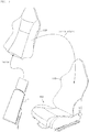
- the biological signal detector 1 described above is arranged inside a seat cover 120 covering a seatback frame 110 of the vehicle seat 100 as illustrated in Fig. 3 , for example.
- the three-dimensional knitted material 10, the three-dimensional knitted material supporting member 15, the film 16, the plate-shaped foam bodies 21 and 22, the vibration sensor 30 and the like constituting the biological signal detector 1 are preferably unitized in advance.
- the biological signal detector 1 of the above-described embodiment was placed on a measuring plate, a spot where the three-dimensional knitted material 10 was arranged was pressurized by a pressure plate having a diameter of 30 mm, and the load-deflection characteristics were examined.
- a spot where the three-dimensional knitted material 10 was arranged was pressurized by a pressure plate having a diameter of 30 mm, and the load-deflection characteristics were examined.
- the plate-shaped foam bodies 21 and 22 and the three-dimensional knitted material supporting member 15 a bead foam body having an average bead diameter of approximately 5 mm and sliced to the thickness of 3 mm was used.
- the three-dimensional knitted material 10 was a product made by Suminoe Textile Co., Ltd., the product number: 49011D and having a thickness of 10 mm.
- the film 16 As the film 16, a product made by Sheedom Corporation, the product number of "DUS605-CDR" was used (film specification). Moreover, the biological signal detector 1 of the embodiment was laminated on the back side of the product name "Twin Lumbar” made by Delta Tooling, which is a drive cushion formed from a three-dimensional knitted material having an excellent external vibration removing effect, the laminated body was placed on the measuring plate in that state, and the load-deflection characteristics were measured similarly.
- Twin Lumbar made by Delta Tooling
- the biological signal measuring device 1 (PEN specification) manufactured by using a polyethylene terephthalate (PEN) fiber by Teijin as the film 16 and by disposing it so as to cover both the two three-dimensional knitted materials 10 and 10, as illustrated in Fig. 2
- the biological signal measuring device 1 (Espansione specification) manufactured by using the product name "Espansione” by KB Seiren Ltd. as the film 16 and by disposing it so as to cover both the two three-dimensional knitted materials 10 and 10, as illustrated in Fig. 2
- the load-deflection characteristics were measured similarly to the above. The result is illustrated in Fig. 4 .
- the biological signal detector 1 of the embodiment had a spring constant within a range up to the load of 30N was 6 to 10 N/mm and that was substantially the same as the spring constant in the load range of 40 to 60 N of the load-deflection characteristics of the muscle on the back part. Moreover, in a state where it was laminated on the product name "Twin Lumbar", the spring constant was further lower and became extremely close to the load-deflection characteristics within the load range around 10 N of the load-deflection characteristics of the muscle of the back part of a human being.
- the biological signal measuring device 1 of this embodiment by using the biological signal measuring device 1 of this embodiment and by covering it with a drive cushion made of a three-dimensional knitted material similarly to the product name "Twin Lumbar" formed from the three-dimensional knitted material or a seat cover made of the three-dimensional knitted material, it is known that a difference between a pressure generated by vibration of the back part muscle of a human being (internal pressure) and a pressure involved in compression and recovery of the three-dimensional knitted material (external pressure) no longer exists, and the heart rate, respiration, atrial and aortic vibrations and the like can be easily propagated as solid vibration.
- the biological signal measuring device 1 employing a material made of a bead foam body having a thickness of 5 mm instead of the plate-shaped foam bodies 21 and 22 made of a bead foam body having a thickness of 3 mm and the three-dimensional knitted material supporting member 15 was manufactured. This was set on a seatback made of resin, a subject was seated, and a biological signal was measured. The device was set on such a region that the three-dimensional knitted material 10 can detect vibration generated by motion involved in pumping of the atrium and aorta (particularly, the "descending aorta") and motion of an aortic valve.
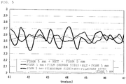
- Fig. 5 illustrates an output original waveform of the vibration sensor 30 at that time.
- Fig. 5 illustrates an output original waveform of the vibration sensor 30 at that time.
- the phrase “FOAM 5 mm + FILM (HUMAN SIDE) + NET + FILM (SEAT SIDE) + FOAM 5 mm” has the completely same structure as the biological signal detector 1 illustrated in Fig. 1
- the phrase “FOAM 5 mm + FILM (HUMAN SIDE) + NET + FOAM 5 mm” has the structure obtained by removing the film on the seatback side from the structure in Fig. 1
- the phrase “FOAM 5 mm + NET + FOAM 5 mm” has the structure obtained by removing the both films on the human side and the seat back side from the structure in Fig. 1 .
- the biological signal (vibration of the aorta involved in pumping) is captured, but as compared with the case where the film is not arranged, amplitude in the case where the film is disposed only on the side in contact with a human being is larger, and moreover, if the film is arranged on the both sides of the three-dimensional knitted material 10, the amplitude becomes much larger.
- the amplification effect realized by combination with the membrane vibration of the film 16 is high.
- the biological signal detector 1 used in the test example 1 (the type using the product number "DUS605-CDR" by Sheedom Co., Ltd. as the film 16) was stacked on the back side of the product name "Twin Lumbar” made by Delta Tooling which is a drive cushion formed of the three-dimensional knitted material having an excellent external vibration removing effect and placed on the measuring plate in that state, and the load-deflection characteristics were measured similarly.
- the biological signal measuring device 1 manufactured by using the product name "Espansione” by KB Seiren Ltd. as the film 16 and by disposing it so as to cover both the two three-dimensional knitted materials 10 and 10, as illustrated in Fig. 2 were stacked on the back side of the product name "Twin Lumbar” made by Delta Tooling and attached to a front passenger seat of a vehicle and the actual-vehicle running test was conducted.
- PEN polyethylene naphthalate
- Fig. 6(A) illustrates a frequency analysis result of an original waveform outputted from the vibration sensor 30 at that time and a waveform (filtered waveform) obtained by removing the noise such as a body motion component and the like from the original waveform by filtering.
- the subject was the same as that in the test example 2, and the heart rate of this subject during activity metabolism is approximately 70 times a minute on an average, that is, approximately 1.3 Hz. From Fig.
- the biological signal measuring device 1 used in the test example 1 has the highest peak in the vicinity of 1.2 to 1.4 Hz in the original waveform, while the noise in the vicinity of 0.5 Hz and 0.9 Hz is removed in the filtered waveform, which has a clear peak in the vicinity of 1.2 to 1.4 Hz, and that the atrial and aortic vibration including a heart rate component was reliably detected.
- a prior-art air-bag type biological signal detector was manufactured by using two films of the product number "DUS605-CDR" by Sheedom Co., Ltd. by positioning the three-dimensional knitted material inside, and further by sandwiching a tube between the two films and sealing the peripheral edge by vibration welding. A capacitor-type microphone sensor was arranged in the tube, and pneumatic pressure fluctuation in the sealed air bag was measured.
- This air-bag type biological signal detector is stacked on the back side of the product name "Twin Lumbar” made by Delta Tooling and attached to a driver seat of a vehicle similarly to the above and the actual-vehicle running test was conducted.
- FIG. 6(B) illustrates a frequency analysis result of an original waveform outputted from the microphone sensor at that time and a waveform (filtered waveform) obtained by removing the noise such as a body motion component and the like from the original waveform by filtering.
- the original waveform has a peak also in the vicinity of 1.2 Hz in addition to 0.5 Hz, 0.8 Hz, and 1.0 Hz
- the filtered waveform has a peak in the vicinity of 0.8 Hz, 1.0 Hz, and 1.2 Hz, and the highest peak among them was 1.0 Hz. That is, in the case of the air bag type, the resonance frequency was 1.0 Hz which was shifted from 1.2 to 1.4 Hz which is the heart rate component of the subject during activity metabolism. Therefore, the biological signal detector 1 of this embodiment coincided more with the purpose of detecting the biological signal component mainly of the pulse wave of the heart (including the atrial and aortic vibrations) and had more excellent sensitivity than the prior-art air-bag type.
- Fig. 7(A) illustrates an original waveform outputted from the microphone sensor which is the vibration sensor 30, and Fig. 7(B) is a diagram illustrating a waveform (filtered waveform) obtained by removing the noise such as a body motion component and the like from the original waveform by filtering.
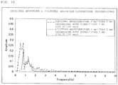
- Figs. 8 to 10 are diagrams illustrating frequency analysis results of the original waveform and the filtered waveform in Figs. 7(A) and 7(B) , in which Fig. 8 illustrates a frequency analysis result using the product number "DUS605-CDR" by Sheedom Co. , Ltd. , Fig. 9 illustrates the result using polyethylene naphthalate (PEN) fiber by Teijin, and Fig. 10 illustrates the result using the product name "Espansione" by KB Seiren Ltd.
- PEN polyethylene naphthalate
- Fig. 8 From Fig. 8 , it can be observed that the peak of the filtered waveform is within a range of 1.2 to 1.4 Hz, and the heart rate component of this subject is reliably detected.
- Fig. 9 there are peaks having substantially the same height in the vicinity of 0.7 to 0.8 Hz and 1.0 Hz, and Fig. 10 has a marked peak within a range of 0.8 to 0.9 Hz and a small peak in the vicinity of 1.3 Hz. In the both cases, the highest peak was shifted from the heart rate component of the subject. From this fact, it is preferable to use the product number "DUS605-CDR" by Sheedom Co. , Ltd.
- the film 16 in order to detect the atrial and aortic vibrations including the heart rate component of this subject, but if a frequency of a target to be sampled is different, such as when a respiration rate is to be measured, for example, or when the atrial and aortic vibrations including the heart rate during sleep with muscles in a relaxed state (both lower than that while being awake) is to be detected, those using Espansione are suitable. Moreover, it is also possible to capture the biological signal with further different frequencies by providing a plurality of types of these films in lamination. Therefore, the film 16 has a function of adjusting the resonance frequency of the biological signal measuring device 1 by varying the type and the number of disposed films.
- the biological signal detector 1 of the "FILM BOTH SIDES" type in the test example 4 was stacked on the back side of the product name "Twin Lumbar” by Delta Tooling and attached to a front passenger seat of a vehicle. Then, an actual vehicle was driven, and the state of the subject was measured. The result is illustrated in Figs. 11(A) to 11(D) , in which Fig. 11(D) illustrates a comprehensive determination result of the state of the subject. This is based on the technology of Japanese Unexamined Patent Application Publication No.
- a method in which a time-series waveform of a frequency is acquired from the time-series waveform of a detected biological signal, a time window having a predetermined time width is set, inclination of the frequency is acquired by the least square method, and the time-series waveform of the frequency is acquired by using the sign of the frequency inclination time-series waveform when the time-series waveform is outputted, the sign of an integrated waveform of the frequency inclination time-series waveform, and a point where the sign changes from positive to negative in the time-series waveform of the detected biological signal and a method (hereinafter referred to as a "peak detection method") in which the time-series waveform is subjected to smoothing differentiation and the time-series waveform is acquired by using a maximum value (peak) are used, and comparison of absolute values of the frequency inclination time-series waveforms
- Fig. 11 is a result of the test conducted similarly to Figs. 10 using the biological signal detector 1 of the "PEN both sides" type in the test example 4.
- Figs. 12 are a result of the test conducted similarly by using the biological signal measuring device 1 of the "Espansione both sides" type in the test example 4. Examining Fig. 12(D) , there is a slight difference between the sense of the subject and the determination result in Fig. 9(D) . From this fact, it can be considered that a highly elastic fiber unwoven cloth with extremely high elongation and recovery rates is not very suitable for a film when the atrial and aortic vibrations during the activity metabolism are to be captured as above. However, if a target to be sampled is different or in the case of determination of the state during sleep, use of the elastic fiber unwoven cloth like Espansione is preferable as described above.
- the biological signal detector 1 of the "film both sides” type is used for measurement of the biological signal during the activity metabolism and the biological signal measuring device 1 of the "PEN both sides” type or the “Espansione both sides” type is used for measurement of the biological signal during resting metabolism (relaxed state) or sleep metabolism, for example. It is needless to say that the biological signal measuring device 1 of the "PEN both sides” type or the “Espansione both sides” type might be more suitable for detection of atrial and aortic vibrations including the heart rate component depending on the subject.
- the polyethylene naphthalate (PEN) fiber by Teij in itself is plastically deformed and functions as a damping element, but if a load is applied to the biological signal measuring device 1, the elasticity of the three-dimensional knitted material 10 arranged therein acts. Moreover, if the product name "Espansione" by KB Seiren Ltd. is used, since the spring elements are arranged in series by being combined with the elastic support of the three-dimensional knitted material 10, more flexible spring characteristics are created.
- the biological signal measuring device 1 of the "PEN both sides” type or the “Espansione both sides” type has a resonance frequency different from that of the biological signal detector 1 of the "film both sides” type, and it is preferable to use them according to the type of a signal to be sampled or age, sex and the like of the subject.
- the polyethylene naphthalate (PEN) fiber by Teijin and the product name "Espansione” by KB Seiren Ltd. are preferable since they have air permeability from the viewpoint of preventing dampness.
- the biological signal detector 1 of the above-described embodiment can reliably detect the biological signal of a human being as solid vibration. Moreover, since sealing performance does not have to be considered and it is only necessary to sequentially stack the plate-shaped foam bodies 21 and 22, the three-dimensional knitted materials 10 and 10, and the films 16 and 16, a manufacturing work is easy and manufacture is possible with a low cost, which is suitable for mass production.
- the biological signal measuring device of the present invention can be used for sampling a biological signal by being attached to a range corresponding to the back part of a human being in bedding (bed, futon and the like) supporting a human body and a seat structure (a vehicle seat, a desk chair, a massaging chair, a sofa and the like).
Landscapes
- Health & Medical Sciences (AREA)
- Life Sciences & Earth Sciences (AREA)
- Medical Informatics (AREA)
- Molecular Biology (AREA)
- Veterinary Medicine (AREA)
- Biophysics (AREA)
- Pathology (AREA)
- Engineering & Computer Science (AREA)
- Biomedical Technology (AREA)
- Heart & Thoracic Surgery (AREA)
- Public Health (AREA)
- Physics & Mathematics (AREA)
- Surgery (AREA)
- Animal Behavior & Ethology (AREA)
- General Health & Medical Sciences (AREA)
- Cardiology (AREA)
- Physiology (AREA)
- Measurement Of The Respiration, Hearing Ability, Form, And Blood Characteristics Of Living Organisms (AREA)
- Measuring And Recording Apparatus For Diagnosis (AREA)
- Measuring Pulse, Heart Rate, Blood Pressure Or Blood Flow (AREA)
Description
- The present invention relates to a biological signal detector which detects a biological signal of a human being such as respiration, heart rate, atrial and aortic vibrations.
- As a device which detects a biological signal of a human being such as heart rate, respiration, body motion and the like,
Patent Literatures 1 to 8 are disclosed, for example. They use a sealed air bag and measures pneumatic fluctuation in the air bag to detect a human biological signal from obtained pneumatic pressure fluctuation data. -
- Patent Literature 1: Japanese Unexamined Patent Application Publication No.
H2-26963 - Patent Literature 2: Japanese Unexamined Patent Application Publication No.
H11-19056 - Patent Literature 3: Japanese Unexamined Patent Application Publication No.
2001-286448 - Patent Literature 4: Japanese Patent No.
3242631 - Patent Literature 5: Japanese Patent No.
3419732 - Patent Literature 6: Japanese Patent No.
3419733 - Patent Literature 7: Japanese Patent No.
3495982 - Patent Literature 8: Japanese Patent No.
3513497 - Patent Literature 9: Japanese Unexamined Patent Application Publication No.
2007-90032 -
JP 10014888 -
US 2004/0245036 A1 discloses a bio-signal detector to detect a heart rate and a respiratory rate so that the determination of a kind of a seat load placed on a seat can be made. That is, whether the seat load is a human or an object is determined, and if it is the human, then the physique size is determined to be small or large (the level of the physique size is determined). Accordingly, as compared with the means based only on a weight of the seat load, the determination result is highly reliable. Besides, with the use of the bio-signal detector, the discrimination between the human and the object is ensured. Moreover, a structure additionally including a weight sensor allows the determination of the physique size in more accurate manner. -
JP 2005-074059 A - The devices disclosed in
Patent Literatures 1 to 8 all measure the pneumatic pressure fluctuation in the air bag with a microphone sensor or a pressure sensor. However, vibration on the body surface accompanying respiration or heart rate which is a human biological signal has extremely small amplitude. Thus, a change in the pneumatic pressure in the air bag generated with such small amplitude of the body surface is also extremely small and can be disturbed by noise. It is possible to capture such small pneumatic pressure fluctuation under an environment without an influence of noise or so-called external vibration, but a large amount of the external vibration is captured under the environment of the external vibration. Therefore, if the device is set on a vehicle seat, for example, the external vibration inputted through a vehicle body during running or body motion prevents detection of a human biological signal. Thus, it is extremely difficult to capture vibration with small amplitude such as heart rate or respiration by applying the technology disclosed inPatent Literatures 1 to 8 to a vehicle seat, and onlyPatent Literature 8 discloses that it is possible to detect body motion of a driver which is a change having large amplitude and causes large pneumatic pressure fluctuation. - On the other hand, the applicant discloses a biological signal detector in which an air bag with a small volume is used for detecting pressure fluctuation and a three-dimensional knitted material having a load characteristic close to the load characteristic of a human muscle is arranged therein as
Patent Literature 9. As a seat to be mounted on a vehicle, a seat having a structure that can effectively remove external vibration is employed so that a biological signal with small amplitude such as heart rate and respiration can be detected from pneumatic pressure fluctuation in the air bag by using a special algorithm for processing a detection signal. - According to the technology disclosed in
Patent Literature 9, the biological signal such as heart rate, respiration and the like can be detected by using the air bag with a small volume and the special algorithm as described above, but moreover, it is preferable that a micro vibration involved in heart rate, respiration, atrial and aortic vibrations can be detected with greater sensitivity. With the technology ofPatent Literature 9, it is necessary to sandwich the three-dimensional knitted material with two plastic films and weld the peripheral edges of the two plastic films by using means such as vibration welding or the like, which causes a problem of a relatively high manufacturing cost. Particularly, in order to apply processing to keep air tightness at a predetermined level or more in a state where the three-dimensional knitted material is inserted therein, a lead wire of a microphone sensor or the like needs to be taken out, requiring skilled work. - The present invention was made in view of the above and has an object to provide a biological signal detector that can detect a biological signal with small amplitude such as heart rate, respiration, atrial and aortic vibrations or the like with greater sensitivity than before and further, has a simple configuration and can be made easily and manufactured with a low cost.
- According to the present invention, there is provided a biological signal detector as set out in
Claim 1. - Optional features are set out in the dependent claims.
- The present invention has the mechanical amplification device provided with the three-dimensional knitted material and the plate-shaped foam body stacked on the periphery of the three-dimensional knitted material. The mechanical amplification device has a film is disposed between the three-dimensional knitted material and the plate-shaped foam body and is configured such that the vibration sensor is attached to this mechanical amplification device. The micro vibration on the body surface by the human biological signal such as heart rate, respiration, atrial and aortic vibrations and the like is propagated to the plate-shaped foam body, the film, and the three-dimensional knitted material, and the membrane vibration is generated in the plate-shaped foam body and the film, while the string vibration of the fiber is generated in the three-dimensional knitted material. Moreover, the three-dimensional knitted material is composed of the connecting yarn disposed between the pair of ground knitted fabrics and is provided with the load-deflection characteristic close to the load-deflection characteristic of a human muscle. Therefore, by making the load-deflection characteristic of the mechanical amplification device including the three-dimensional knitted material close to that of the muscle and arranging the mechanical amplification device adjacent to the muscle, a difference between internal and external pressures between the muscle and the three-dimensional knitted material becomes equal, and a biological signal such as heart rate, respiration, atrial and aortic vibrations and the like can be transmitted accurately, whereby the string vibration can be generated in a fiber (or particularly the connecting yarn) constituting the three-dimensional knitted material. Moreover, the plate-shaped foam body stacked on the three-dimensional knitted material is a bead foam body and can easily generate membrane vibration in each bead due to flexible elasticity and small density of the bead. The film can easily generate membrane vibration since a predetermined tension is generated by means of fixation of the peripheral edge portion and elastic support by the three-dimensional knitted material close to the load-deflection characteristic of a human muscle. That is, according to the present invention, the membrane vibration is generated in the plate-shaped foam body or the film in the mechanical amplification device having the load-deflection characteristic close to the load-deflection
characteristic of the muscle by a biological signal such as heart rate, respiration, atrial and aortic vibrations and the like, and the string vibration is generated in the three-dimensional knitted material having the load-deflection characteristic close to the load-deflection characteristic of the human muscle. The string vibration of the three-dimensional knitted material influences the membrane vibration of the film and the like again, and these vibrations act in a superposed manner. As a result, the vibration inputted from the body surface with the biological signal is directly detected by the vibration sensor as solid vibration amplified by superposition of the string vibration and the membrane vibration. - If the pneumatic pressure fluctuation in the sealed bag is detected as in the prior-art technology, since the volume and the pressure are inversely proportional, the pressure fluctuation cannot be easily detected unless the volume of the sealed bag is made small. In contrast, according to the present invention, instead of the pneumatic pressure fluctuation, the amplified solid vibration propagated to the mechanical amplification device (the three-dimensional knitted material, the plate-shaped foam body, and the film) is detected as described above. Thus, the capacity (volume) is rarely limited from the viewpoint of detection sensitivity, and the vibration with small amplitude involved in heart rate, respiration, atrial and aortic vibrations and the like can be detected with good sensitivity. Accordingly, the device can handle people with various physical sizes. As described above, the present invention is suitable as a biological signal detector under an environment such as a vehicle seat used by people with various physical sizes and into which various external vibrations are inputted. Moreover, since it is not necessary to form a sealed structure, a manufacturing process is simplified and a manufacturing cost can be lowered, which is suitable for mass production.
-
-
Fig. 1 is an exploded perspective diagram illustrating a configuration of a biological signal detector according to an embodiment of the present invention. -
Fig. 2 is an exploded perspective diagram illustrating a film in use according to another form in the biological signal detector inFig. 1 . -
Fig. 3 is a diagram illustrating a process of arranging the biological signal detector inFig. 1 in an automobile seat. -
Fig. 4 is a diagram illustrating a load-deflection characteristic of the biological signal detector. -
Fig. 5 is a diagram illustrating an output original waveform when a biological signal is measured by the biological signal detector. -
Fig. 6(A) is a diagram illustrating a frequency analysis result of an original waveform outputted from avibration sensor 30 in a biological signal measuring device of the embodiment and a waveform (filtered waveform) obtained by removing noise such as a body motion component and the like from the original waveform by filtering, andFig. 6(B) is a diagram illustrating a frequency analysis result of an original waveform outputted from a sensor in a prior-art air-bag type biological signal detector and a waveform (filtered waveform) obtained by removing the noise such as a body motion component and the like from the original waveform by filtering. -
Fig. 7 (A) illustrates an original waveform outputted from a microphone sensor which is a vibration sensor in a test example 4, andFig. 7 (B) is a diagram illustrating a waveform (filtered waveform) obtained by removing the noise such as a body motion component and the like from the original waveform by filtering. -
Fig. 8 is a diagram illustrating a frequency analysis result of an original waveform and a filtered waveform of a "FILM BOTH SIDE" type biological signal detector illustrated inFigs . 7(A) and 7(B) . -
Fig. 9 is a diagram illustrating a frequency analysis result of an original waveform and a filtered waveform of a biological signal detector of a type using another film illustrated inFigs. 7(A) and 7(B) . -
Fig. 10 is a diagram illustrating a frequency analysis result of an original waveform and a filtered waveform of a biological signal detector of a type using still another film illustrated inFigs. 7(A) and 7(B) . -
Figs. 11(A) to 11(D) are diagrams illustrating determination results of states of subjects in an actual-vehicle running test conducted with the "film both side" type biological signal detector attached. -
Figs. 12(A) to 12(D) are diagrams illustrating determination results of states of subjects in the actual-vehicle running test conducted with the biological signal detector of a type using another film attached. -
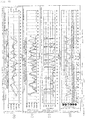
Figs. 13(A) to 13(D) are diagrams illustrating determination results of states of subjects in the actual-vehicle running test conducted with the biological signal detector of a type using still another film attached. Description of Embodiments - The present invention will be described below in further detail on the basis of an embodiment of the present invention illustrated in the drawings.
Fig. 1 is a configuration diagram illustrating abiological signal detector 1 according to this embodiment. Thebiological signal detector 1 includes a three-dimensionalknitted material 10, a three-dimensional knittedmaterial supporting member 15, afilm 16, plate-shapedfoam bodies vibration sensor 30. - The three-dimensional
knitted material 10 is, as disclosed in Japanese Unexamined Patent Application Publication No.2002-331603 - One of the ground knitted fabrics is formed of a flat knitted fabric composition (fine stitch) which is continuous both in a wale direction and a course direction from a yarn obtained by twisting a monofilament, for example, while the other ground knitted fabric is formed having a knitted structure having a honeycomb-shaped (hexagonal) mesh from a yarn obtained by twisting a short fiber, for example. It is needless to say that the knitted fabric composition is optional and its combination is also optional such that a knitted fabric composition other than the fine-stitch composition or the honeycomb-shape can be employed, alternatively, the fine-stitch composition can be employed for the both. The connecting yarn is knitted between the two ground knitted fabrics so that the one ground knitted fabric and the other ground knitted fabric maintain a predetermined interval. In this embodiment, since the solid vibration of the three-dimensional knitted material or particularly the string vibration of the connecting yarn is to be detected, the connecting yarn is preferably formed of a monofilament, but the connecting yarn may also be formed of a multifilament in order to adjust a resonance frequency in accordance with the type of a biological signal to be sampled.
- Moreover, the three-dimensional
knitted material 10 is provided with a load-deflection characteristic in a thickness direction within a range up to the load of 100 N when being placed on a measuring plate and pressurized by a pressure plate having a diameter of 30 mm or a diameter of 98 mm and with a spring constant close to the load-deflection characteristic of a muscle in the buttocks of a human being. Specifically, it is preferable to use the material having the spring constant within a range of 0.1 to 5 N/mm when being pressurized by a pressure plate, having the diameter of 30 mm or the material having the spring constant within a range of 1 to 10 N/mm when being pressurized by a pressure plate having the diameter of 98 mm. By means of approximation to the load-deflection characteristic of the muscle in the buttocks of a human being, the three-dimensional knitted material is balanced with the muscle, and when a biological signal of heart rate, respiration, atrial and aortic vibrations and the like is propagated, the three-dimensional knitted material generates the vibration similar to that in the human muscle, and the biological signal can be propagated without large attenuation. - As such three-dimensional knitted material, the following may be used, for example. Each of the three-dimensional knitted materials can be used by being stacked in plural as necessary.
- (1) Product number: 49076D (by Suminoe Textile Co. , Ltd.) Material:
- Ground knitted fabric on the front side: Twisted yarn of polyethylene terephthalate fiber false twisted yarn of 300 decitex/288f and polyethylene terephthalate fiber false twisted yarn of 700 decitex/192f
- Ground knitted fabric on the back side: Combination of polyethylene terephthalate fiber false twisted yarn of 450 decitex/108f and polytrimethylene terephthalate monofilament of 350 decitex/1f
- Connecting yarn: polytrimethylene terephthalate monofilament of 350 decitex/1f
- (2) Product number: 49011D (by Suminoe Textile Co. , Ltd.) Material:
- Ground knitted fabric (warp) : Polyethylene terephthalate fiber false twisted yarn of 600 decitex/192f
- Ground knitted fabric (weft) : Polyethylene terephthalate fiber false twisted yarn of 300 decitex/72f
- Connecting yarn: polyethylene terephthalate monofilament of 800 decitex/1f
- (3) Product number: 49013D (by Suminoe Textile Co., Ltd.) Material:
- Ground knitted fabric on the front side: Two twisted yarns of polyethylene terephthalate fiber false twisted yarn of 450 decitex/108f
- Ground knitted fabric on the back side: Two twisted yarns of polyethylene terephthalate fiber false twisted yarn of 450 decitex/108f
- Connecting yarn: polytrimethylene terephthalate monofilament of 350 decitex/1f
- (4) Product number : 69030D (by Suminoe Textile Co., Ltd.) Material:
- Ground knitted fabric on the front side: Two twisted yarns of polyethylene terephthalate fiber false twisted yarn of 450 decitex/144f
- Ground knitted fabric on the back side: Combination of polyethylene terephthalate fiber false twisted yarn of 450 decitex/144f and polytrimethylene terephthalate monofilament of 350 decitex/1f
- Connecting yarn: polytrimethylene terephthalate monofilament of 350 decitex/1f
- (5) Product number: T24053AY5-1S by Asahi Kasei Fibers Corporation
- The plate-shaped
foam bodies foam bodies
vibration by means of characteristics of a spherical resin film formed by foams constituting individual fine beads. This membrane vibration is transmitted as string vibration to the three-dimensional knitted material, the membrane vibration and the string vibration are superposed with each other, and the biological signal is detected by thevibration sensor 30 which will be described later as mechanical vibration amplified by superposition of the membrane vibration and the string vibration. Therefore, detection of the biological signal is facilitated. - As the plate-shaped
foam bodies foam bodies foam bodies - Here, as the three-dimensional
knitted material 10, a strip-shaped material having a width within a range of 40 to 100 mm and a length within a range of 100 to 300 mm is used. In this embodiment, in order to reduce a sense of discomfort when the back part of a human being is in contact the device, two strips are disposed on a target, sandwiching a portion corresponding to the spine. It is preferable that the three-dimensionalknitted material 10 is configured to be supported by the three-dimensional knittedmaterial supporting member 15 as illustrated inFig. 1 so that the three-dimensionalknitted materials 10 can be arranged at predetermined positions easily. The three-dimensional knittedmaterial supporting member 15 is molded having a plate shape, and two vertically long throughholes material supporting member 15 is composed of the bead foam bodies formed having a plate shape similarly to the above-described plate-shapedfoam bodies material supporting member 15 is formed of a bead foam body are the same as those of the above-described plate-shapedfoam bodies foam bodies knitted materials material supporting member 15 in order that the membrane vibration is generated more remarkably by the biological signal. - In a state where the two three-dimensional
knitted materials holes material supporting member 15, thefilms knitted materials films holes holes knitted materials 10 and 10) are preferably set to positions corresponding to regions where vibration caused by motion involved in pumping of atrium and aorta (particularly "descending aorta") and motion of an aortic valve can be detected. As a result, the three-dimensionalknitted materials foam bodies material supporting member 15, and the plate-shapedfoam bodies material supporting member 15 function as a resonance box (resonant box). - Moreover, it is preferable that the three-dimensional
knitted materials material supporting member 15 in use. That is, such a thickness relationship is realized that, when the three-dimensionalknitted materials holes knitted materials holes films holes knitted materials films films knitted materials films knitted materials film 16 is provided on at least either one of them. - Since the connecting yarn of the three-dimensional
knitted materials films foam bodies films foam bodies - In order to give the preliminary compression to the three-dimensional
knitted materials films material supporting member 15 as described above. However, instead of disposition of the films in correspondence with each three-dimensionalknitted material 10 as inFig. 1 , it is possible to use thefilm 16 having a size that can cover both the two three-dimensionalknitted materials Fig. 2 . - As the
films films - The
vibration sensor 30 is fastened and disposed on either one of the three-dimensionalknitted materials 10 before the above-describedfilms knitted material 10 is composed of a pair of ground knitted fabrics and the connecting yarn, and since the string vibration of each connecting yarn is transmitted to thefilms foam bodies vibration sensor 30 is preferably fastened to the surface of the three-dimensional knitted material 10 (surface of the ground knitted fabric) at asensing portion 30a. As thevibration sensor 30, a microphone sensor or particularly a capacitor-type microphone sensor is preferably used. In this embodiment, since it is not necessary to consider sealing performance at a portion where the microphone sensor is arranged (that is, the throughhole 15a for arrangement in which the three-dimensionalknitted material 10 is arranged), a lead wire of the microphone sensor can be wired easily. In this embodiment, as described above, the vibration on the body surface through the muscle of a human being involved in the biological signal is propagated not only to the three-dimensionalknitted material 10 but also to the plate-shapedfoam bodies film 16, and they are vibrated (string vibration, membrane vibration), the superposed and amplified. Thus, thevibration sensor 30 can fix thesensing portion 30a not only to the three-dimensionalknitted material 10 but also to the plate-shapedfoam bodies film 16 constituting a vibration transmission path. In this embodiment, since the three-dimensionalknitted material 10, the three-dimensional knittedmaterial supporting member 15, the plate-shapedfoam bodies film 16 mechanically amplify the biological signal, they constitute the mechanical amplification device. - The
biological signal detector 1 described above is arranged inside aseat cover 120 covering aseatback frame 110 of thevehicle seat 100 as illustrated inFig. 3 , for example. In order to facilitate an arrangement work, the three-dimensionalknitted material 10, the three-dimensional knittedmaterial supporting member 15, thefilm 16, the plate-shapedfoam bodies vibration sensor 30 and the like constituting thebiological signal detector 1 are preferably unitized in advance. - The
biological signal detector 1 of the above-described embodiment was placed on a measuring plate, a spot where the three-dimensionalknitted material 10 was arranged was pressurized by a pressure plate having a diameter of 30 mm, and the load-deflection characteristics were examined. As the plate-shapedfoam bodies material supporting member 15, a bead foam body having an average bead diameter of approximately 5 mm and sliced to the thickness of 3 mm was used. The three-dimensionalknitted material 10 was a product made by Suminoe Textile Co., Ltd., the product number: 49011D and having a thickness of 10 mm. As thefilm 16, a product made by Sheedom Corporation, the product number of "DUS605-CDR" was used (film specification). Moreover, thebiological signal detector 1 of the embodiment was laminated on the back side of the product name "Twin Lumbar" made by Delta Tooling, which is a drive cushion formed from a three-dimensional knitted material having an excellent external vibration removing effect, the laminated body was placed on the measuring plate in that state, and the load-deflection characteristics were measured similarly. - Regarding the biological signal measuring device 1 (PEN specification) manufactured by using a polyethylene terephthalate (PEN) fiber by Teijin as the
film 16 and by disposing it so as to cover both the two three-dimensionalknitted materials Fig. 2 , and the biological signal measuring device 1 (Espansione specification) manufactured by using the product name "Espansione" by KB Seiren Ltd. as thefilm 16 and by disposing it so as to cover both the two three-dimensionalknitted materials Fig. 2 , the load-deflection characteristics were measured similarly to the above. The result is illustrated inFig. 4 . - As illustrated in
Fig. 4 , thebiological signal detector 1 of the embodiment had a spring constant within a range up to the load of 30N was 6 to 10 N/mm and that was substantially the same as the spring constant in the load range of 40 to 60 N of the load-deflection characteristics of the muscle on the back part. Moreover, in a state where it was laminated on the product name "Twin Lumbar", the spring constant was further lower and became extremely close to the load-deflection characteristics within the load range around 10 N of the load-deflection characteristics of the muscle of the back part of a human being. Therefore, by using the biologicalsignal measuring device 1 of this embodiment and by covering it with a drive cushion made of a three-dimensional knitted material similarly to the product name "Twin Lumbar" formed from the three-dimensional knitted material or a seat cover made of the three-dimensional knitted material, it is known that a difference between a pressure generated by vibration of the back part muscle of a human being (internal pressure) and a pressure involved in compression and recovery of the three-dimensional knitted material (external pressure) no longer exists, and the heart rate, respiration, atrial and aortic vibrations and the like can be easily propagated as solid vibration. - The biological
signal measuring device 1 employing a material made of a bead foam body having a thickness of 5 mm instead of the plate-shapedfoam bodies material supporting member 15 was manufactured. This was set on a seatback made of resin, a subject was seated, and a biological signal was measured. The device was set on such a region that the three-dimensionalknitted material 10 can detect vibration generated by motion involved in pumping of the atrium and aorta (particularly, the "descending aorta") and motion of an aortic valve.Fig. 5 illustrates an output original waveform of thevibration sensor 30 at that time. InFig. 5 , the phrase "FOAM 5 mm + FILM (HUMAN SIDE) + NET + FILM (SEAT SIDE) +FOAM 5 mm" has the completely same structure as thebiological signal detector 1 illustrated inFig. 1 , the phrase "FOAM 5 mm + FILM (HUMAN SIDE) + NET +FOAM 5 mm" has the structure obtained by removing the film on the seatback side from the structure inFig. 1 , and the phrase "FOAM 5 mm + NET +FOAM 5 mm" has the structure obtained by removing the both films on the human side and the seat back side from the structure inFig. 1 . - In all cases, the biological signal (vibration of the aorta involved in pumping) is captured, but as compared with the case where the film is not arranged, amplitude in the case where the film is disposed only on the side in contact with a human being is larger, and moreover, if the film is arranged on the both sides of the three-dimensional
knitted material 10, the amplitude becomes much larger. Thus, it is known that the amplification effect realized by combination with the membrane vibration of thefilm 16 is high. - The
biological signal detector 1 used in the test example 1 (the type using the product number "DUS605-CDR" by Sheedom Co., Ltd. as the film 16) was stacked on the back side of the product name "Twin Lumbar" made by Delta Tooling which is a drive cushion formed of the three-dimensional knitted material having an excellent external vibration removing effect and placed on the measuring plate in that state, and the load-deflection characteristics were measured similarly. - Moreover, the biological
signal measuring device 1 manufactured by using a polyethylene naphthalate (PEN) fiber by Teijin as thefilm 16 and by disposing it so as to cover both the two three-dimensionalknitted materials Fig. 2 , and the biologicalsignal measuring device 1 manufactured by using the product name "Espansione" by KB Seiren Ltd. as thefilm 16 and by disposing it so as to cover both the two three-dimensionalknitted materials Fig. 2 , were stacked on the back side of the product name "Twin Lumbar" made by Delta Tooling and attached to a front passenger seat of a vehicle and the actual-vehicle running test was conducted. The device was set on such a region that the three-dimensionalknitted material 10 can detect vibration generated by motion involved in pumping of the atrium and aorta (particularly, the "descending aorta") and motion of an aortic valve.Fig. 6(A) illustrates a frequency analysis result of an original waveform outputted from thevibration sensor 30 at that time and a waveform (filtered waveform) obtained by removing the noise such as a body motion component and the like from the original waveform by filtering. The subject was the same as that in the test example 2, and the heart rate of this subject during activity metabolism is approximately 70 times a minute on an average, that is, approximately 1.3 Hz. FromFig. 6(A) , it can be observed that the biologicalsignal measuring device 1 used in the test example 1 has the highest peak in the vicinity of 1.2 to 1.4 Hz in the original waveform, while the noise in the vicinity of 0.5 Hz and 0.9 Hz is removed in the filtered waveform, which has a clear peak in the vicinity of 1.2 to 1.4 Hz, and that the atrial and aortic vibration including a heart rate component was reliably detected. - On the other hand, a prior-art air-bag type biological signal detector was manufactured by using two films of the product number "DUS605-CDR" by Sheedom Co., Ltd. by positioning the three-dimensional knitted material inside, and further by sandwiching a tube between the two films and sealing the peripheral edge by vibration welding. A capacitor-type microphone sensor was arranged in the tube, and pneumatic pressure fluctuation in the sealed air bag was measured. This air-bag type biological signal detector is stacked on the back side of the product name "Twin Lumbar" made by Delta Tooling and attached to a driver seat of a vehicle similarly to the above and the actual-vehicle running test was conducted.
Fig. 6(B) illustrates a frequency analysis result of an original waveform outputted from the microphone sensor at that time and a waveform (filtered waveform) obtained by removing the noise such as a body motion component and the like from the original waveform by filtering. As a result, the original waveform has a peak also in the vicinity of 1.2 Hz in addition to 0.5 Hz, 0.8 Hz, and 1.0 Hz, while the filtered waveform has a peak in the vicinity of 0.8 Hz, 1.0 Hz, and 1.2 Hz, and the highest peak among them was 1.0 Hz. That is, in the case of the air bag type, the resonance frequency was 1.0 Hz which was shifted from 1.2 to 1.4 Hz which is the heart rate component of the subject during activity metabolism. Therefore, thebiological signal detector 1 of this embodiment coincided more with the purpose of detecting the biological signal component mainly of the pulse wave of the heart (including the atrial and aortic vibrations) and had more excellent sensitivity than the prior-art air-bag type. - Following three biological
signal measuring devices 1 manufactured in the test example 1: - The biological
signal measuring device 1 manufactured by disposing the product number "DUS605-CDR" by Sheedom Co., Ltd. as thefilm 16 on the both sides of each of the two three-dimensionalknitted materials Fig. 1 (noted as "FILM BOTH SIDES" in the figure); - the biological
signal measuring device 1 manufactured by using a polyethylene naphthalate (PEN) fiber by Teijin as thefilm 16 and by disposing it on the both sides of the three-dimensional knitted materials so as to cover both the two three-dimensionalknitted materials Fig. 2 (noted as "PEN BOTH SIDES" in the figure); and - the biological
signal measuring device 1 manufactured by using the product name "Espansione" by KB Seiren Ltd. as thefilm 16 and by disposing it on the both sides of the three-dimensional knitted materials so as to cover both the two three-dimensionalknitted materials Fig. 2 (noted as "ESPANSIONE BOTH SIDES" in the figure) were stacked on the back side of the product name "Twin lumbar" by Delta Tooling and attached to the front passenger seat of a vehicle, respectively, an actual vehicle was driven, and a detection result of each of the biologicalsignal measuring devices 1 was examined. -
Fig. 7(A) illustrates an original waveform outputted from the microphone sensor which is thevibration sensor 30, andFig. 7(B) is a diagram illustrating a waveform (filtered waveform) obtained by removing the noise such as a body motion component and the like from the original waveform by filtering. -
Figs. 8 to 10 are diagrams illustrating frequency analysis results of the original waveform and the filtered waveform inFigs. 7(A) and 7(B) , in whichFig. 8 illustrates a frequency analysis result using the product number "DUS605-CDR" by Sheedom Co. , Ltd. ,Fig. 9 illustrates the result using polyethylene naphthalate (PEN) fiber by Teijin, andFig. 10 illustrates the result using the product name "Espansione" by KB Seiren Ltd. - From
Fig. 8 , it can be observed that the peak of the filtered waveform is within a range of 1.2 to 1.4 Hz, and the heart rate component of this subject is reliably detected. On the other hand, inFig. 9 , there are peaks having substantially the same height in the vicinity of 0.7 to 0.8 Hz and 1.0 Hz, andFig. 10 has a marked peak within a range of 0.8 to 0.9 Hz and a small peak in the vicinity of 1.3 Hz. In the both cases, the highest peak was shifted from the heart rate component of the subject. From this fact, it is preferable to use the product number "DUS605-CDR" by Sheedom Co. , Ltd. as thefilm 16 in order to detect the atrial and aortic vibrations including the heart rate component of this subject, but if a frequency of a target to be sampled is different, such as when a respiration rate is to be measured, for example, or when the atrial and aortic vibrations including the heart rate during sleep with muscles in a relaxed state (both lower than that while being awake) is to be detected, those using Espansione are suitable. Moreover, it is also possible to capture the biological signal with further different frequencies by providing a plurality of types of these films in lamination. Therefore, thefilm 16 has a function of adjusting the resonance frequency of the biologicalsignal measuring device 1 by varying the type and the number of disposed films. - The
biological signal detector 1 of the "FILM BOTH SIDES" type in the test example 4 was stacked on the back side of the product name "Twin Lumbar" by Delta Tooling and attached to a front passenger seat of a vehicle. Then, an actual vehicle was driven, and the state of the subject was measured. The result is illustrated inFigs. 11(A) to 11(D) , in whichFig. 11(D) illustrates a comprehensive determination result of the state of the subject. This is based on the technology of Japanese Unexamined Patent Application Publication No.2009-237802 - In
Fig. 10(D) , phrases like "slightly sleepy", "dazed", "normal" and the like describe the senses felt by the subject during the test, and they substantially matched the determination result inFig. 10(D) . -
Fig. 11 is a result of the test conducted similarly toFigs. 10 using thebiological signal detector 1 of the "PEN both sides" type in the test example 4. - As illustrated in
Fig. 11(D) , the determination result relatively close to the sense of the subject was also obtained in this case, but the determination result by the biologicalsignal measuring device 1 of the above-described "film both sides" type was closer to the sense of the subject. -
Figs. 12 are a result of the test conducted similarly by using the biologicalsignal measuring device 1 of the "Espansione both sides" type in the test example 4. ExaminingFig. 12(D) , there is a slight difference between the sense of the subject and the determination result inFig. 9(D) . From this fact, it can be considered that a highly elastic fiber unwoven cloth with extremely high elongation and recovery rates is not very suitable for a film when the atrial and aortic vibrations during the activity metabolism are to be captured as above. However, if a target to be sampled is different or in the case of determination of the state during sleep, use of the elastic fiber unwoven cloth like Espansione is preferable as described above. - From those facts, it is preferable that the
biological signal detector 1 of the "film both sides" type is used for measurement of the biological signal during the activity metabolism and the biologicalsignal measuring device 1 of the "PEN both sides" type or the "Espansione both sides" type is used for measurement of the biological signal during resting metabolism (relaxed state) or sleep metabolism, for example. It is needless to say that the biologicalsignal measuring device 1 of the "PEN both sides" type or the "Espansione both sides" type might be more suitable for detection of atrial and aortic vibrations including the heart rate component depending on the subject. - The polyethylene naphthalate (PEN) fiber by Teij in itself is plastically deformed and functions as a damping element, but if a load is applied to the biological
signal measuring device 1, the elasticity of the three-dimensionalknitted material 10 arranged therein acts. Moreover, if the product name "Espansione" by KB Seiren Ltd. is used, since the spring elements are arranged in series by being combined with the elastic support of the three-dimensionalknitted material 10, more flexible spring characteristics are created. From these facts , the biologicalsignal measuring device 1 of the "PEN both sides" type or the "Espansione both sides" type has a resonance frequency different from that of thebiological signal detector 1 of the "film both sides" type, and it is preferable to use them according to the type of a signal to be sampled or age, sex and the like of the subject. Moreover, the polyethylene naphthalate (PEN) fiber by Teijin and the product name "Espansione" by KB Seiren Ltd. are preferable since they have air permeability from the viewpoint of preventing dampness. - From the above-described results, it is found that the
biological signal detector 1 of the above-described embodiment can reliably detect the biological signal of a human being as solid vibration. Moreover, since sealing performance does not have to be considered and it is only necessary to sequentially stack the plate-shapedfoam bodies knitted materials films - The biological signal measuring device of the present invention can be used for sampling a biological signal by being attached to a range corresponding to the back part of a human being in bedding (bed, futon and the like) supporting a human body and a seat structure (a vehicle seat, a desk chair, a massaging chair, a sofa and the like).
-
- 1 biological signal detector
- 10 three-dimensional knitted material
- 15 three-dimensional knitted material supporting member
- 15a through hole for arrangement
- 16 film
- 21, 22 plate-shaped foam body
- 30 vibration sensor
Claims (9)
- A biological signal detector (1) comprising:a mechanical amplification device provided with a three-dimensional knitted material (10) for generating string vibration by vibration propagation involved in a human biological signal and a plate-shaped foam body (21,22) stacked on both the front side and the back side of the three-dimensional knitted material (10) for generating membrane vibration by the vibration propagation involved in the human biological signal, and for converting the vibration involved in the human biological signal to amplified solid vibration by a superposing action of the string vibration and membrane vibration; anda vibration sensor (30) attached to the mechanical amplification device for detecting the amplified solid vibration;
whereinthe three-dimensional knitted material (10) includes a pair of ground knitted fabrics arranged separately from each other and a large number of connecting yarns which reciprocate between the pair of ground knitted fabrics and connect the both;the three-dimensional knitted material (10) has a spring constant close to a spring constant obtained from the load-deflection characteristic of a human muscle in a load-deflection characteristic within a range of a load up to 100 N when being pressurized by a pressure plate having a diameter of 30 mm or a diameter of 98 mm;each plate-shaped foam body (21,22) is a bead foam body;the mechanical amplification device has a film (16) laminated between the three-dimensional knitted material (10) and at least one of the plate-shaped foam bodies (21,22) and the membrane vibration of the film is further superposed to the string vibration and the membrane vibration; the mechanical amplification device is further provided with a three-dimensional knitted material supporting member (15) in which a through hole (15a) for arrangement to arrange the three-dimensional knitted material is formed;in a state where the three-dimensional knitted material (10) is arranged in the through hole (15a) for arrangement, the film (16) is laminated on at least either one of the front side and the back side of the three-dimensional knitted material (10), and a peripheral edge portion of the film is fixed to the three-dimensional knitted material supporting member (15);each plate-shaped foam body (21,22) that has a film (16) laminated between that plate-shaped foam body and the three-dimensional knitted material is stacked through the film (16) ;the three-dimensional knitted material supporting member (15) is a bead foam body formed having a plate shape; andthe three-dimensional knitted material (10) has the spring constant within a range of 0.1 to 5 N/mm when being pressurized by the pressure plate having the diameter of 30 mm or the spring constant within a range of 1 to 10 N/mm when being pressurized by the pressure plate having the diameter of 98 mm. - The biological signal detector according to claim 1, wherein
each bead foam body is a foam molded body by a bead method of a resin containing at least any one of polystyrene, polypropylene, and polyethylene. - The biological signal detector according to claim 1 or 2, wherein
each bead foam body is formed having a thickness not more than an average diameter of the bead. - The biological signal detector according to claim 1, wherein
the three-dimensional knitted material (10) has a thickness larger than that of each bead foam body constituting the three-dimensional knitted material supporting member (15). - The biological signal detector according to claim 1, wherein
the connecting yarn is a monofilament. - The biological signal detector according to claim 1, wherein
the connecting yarn is a multifilament. - The biological signal detector according to claim 1 or 2, wherein
a sensing portion of the vibration sensor (30) is fixed to the three-dimensional knitted material (10), the plate-shaped foam bodies(21,22) or a said film (16). - The biological signal detector according to claim 1, wherein
the vibration sensor (30) is a microphone sensor. - The biological signal detector according to claim 1, wherein
the biological signal detector is attached to a range corresponding to the back part of a human being in bedding or a seat structure (100).
Applications Claiming Priority (2)
| Application Number | Priority Date | Filing Date | Title |
|---|---|---|---|
| JP2010014870A JP5679541B2 (en) | 2010-01-26 | 2010-01-26 | Biological signal detection device |
| PCT/JP2011/051413 WO2011093303A1 (en) | 2010-01-26 | 2011-01-26 | Biological signal detector |
Publications (3)
| Publication Number | Publication Date |
|---|---|
| EP2529664A1 EP2529664A1 (en) | 2012-12-05 |
| EP2529664A4 EP2529664A4 (en) | 2013-07-24 |
| EP2529664B1 true EP2529664B1 (en) | 2018-08-22 |
Family
ID=44319290
Family Applications (1)
| Application Number | Title | Priority Date | Filing Date |
|---|---|---|---|
| EP11737016.3A Active EP2529664B1 (en) | 2010-01-26 | 2011-01-26 | Biological signal detector |
Country Status (5)
| Country | Link |
|---|---|
| US (1) | US9050000B2 (en) |
| EP (1) | EP2529664B1 (en) |
| JP (1) | JP5679541B2 (en) |
| CN (1) | CN102939047B (en) |
| WO (1) | WO2011093303A1 (en) |
Families Citing this family (9)
| Publication number | Priority date | Publication date | Assignee | Title |
|---|---|---|---|---|
| CN103263293B (en) * | 2013-03-08 | 2016-08-10 | 蒋琼橙 | A kind of Detachable body surface fixing device |
| JP6460560B2 (en) | 2013-12-07 | 2019-01-30 | 株式会社デルタツーリング | Sound and vibration information collection mechanism and sound and vibration information sensing system |
| CN106618845B (en) * | 2016-12-02 | 2023-11-14 | 常州时和机电科技有限公司 | Safety protection device of low-voltage direct-current heating wearable device |
| GB2563644A (en) * | 2017-06-22 | 2018-12-26 | Zedsen Ltd | Matron |
| FR3069206B1 (en) * | 2017-07-24 | 2020-10-16 | Psa Automobiles Sa | COVER COMPLEX FOR A SEAT OR BACKREST OF A MOTOR VEHICLE SEAT. |
| JP2019077437A (en) | 2017-10-24 | 2019-05-23 | デルタ工業株式会社 | Seat cushion of vehicular seat and vehicular seat |
| WO2019082876A1 (en) | 2017-10-24 | 2019-05-02 | デルタ工業株式会社 | Seat cushion for vehicle seat and vehicle seat |
| CN110641336B (en) * | 2019-10-08 | 2025-01-03 | 惠州市唐群座椅科技股份有限公司 | Airflow sensing seat |
| CN113143666B (en) * | 2021-02-08 | 2023-01-20 | 上海工程技术大学 | Multifunctional home medical autonomous monitoring chair |
Family Cites Families (38)
| Publication number | Priority date | Publication date | Assignee | Title |
|---|---|---|---|---|
| US4715235A (en) * | 1985-03-04 | 1987-12-29 | Asahi Kasei Kogyo Kabushiki Kaisha | Deformation sensitive electroconductive knitted or woven fabric and deformation sensitive electroconductive device comprising the same |
| JPH0226963A (en) | 1988-07-12 | 1990-01-29 | Tsudakoma Corp | Method and apparatus for sensing weft yarn |
| JPH04367651A (en) * | 1991-06-17 | 1992-12-18 | Nippon Telegr & Teleph Corp <Ntt> | Body movement detecting sheet |
| WO1998014096A1 (en) * | 1996-10-04 | 1998-04-09 | Matsushita Electric Industrial Co., Ltd. | Human body sensor for seat |
| JP3596175B2 (en) * | 1996-07-03 | 2004-12-02 | 松下電器産業株式会社 | Body motion detection device |
| JPH1119056A (en) | 1997-06-27 | 1999-01-26 | Arata Nemoto | Method and device for measurement of heart rate |
| JP3462115B2 (en) | 1999-03-29 | 2003-11-05 | 三洋化成工業株式会社 | Non-aqueous electrolyte for dye-sensitized solar cell and solar cell using the same |
| EP1247488A4 (en) | 1999-11-24 | 2004-11-24 | M I Lab Corp | Biological information collecting device comprising closed pneumatic sound sensor |
| JP3419732B2 (en) | 2000-03-31 | 2003-06-23 | 株式会社エム・アイ・ラボ | Biological information collecting device using sealed air type sound sensor |
| JP3242631B2 (en) | 1999-11-24 | 2001-12-25 | 株式会社エム・アイ・ラボ | Biological information collection device using sealed air type sound sensor |
| JP3419733B2 (en) | 2000-04-04 | 2003-06-23 | 株式会社エム・アイ・ラボ | Biological information collecting device using sealed air type sound sensor |
| JP2001286448A (en) | 2000-04-07 | 2001-10-16 | M I Labs:Kk | Biological information collecting device using sealed air type sound sensor |
| JP3495982B2 (en) | 2000-12-21 | 2004-02-09 | 株式会社エム・アイ・ラボ | Driver drowsiness alarm using closed air type sound sensor |
| JP4247810B2 (en) | 2001-02-13 | 2009-04-02 | 富士フイルム株式会社 | Photoelectric conversion element and photovoltaic cell |
| JP4789342B2 (en) | 2001-05-10 | 2011-10-12 | 株式会社デルタツーリング | Cushion material, sheet and method of filing pile yarn |
| JP3513497B2 (en) | 2001-08-21 | 2004-03-31 | 株式会社エム・アイ・ラボ | Biological information collection device using non-airtight air mat |
| JP4277073B2 (en) * | 2003-05-21 | 2009-06-10 | 株式会社デルタツーリング | Seat load body determination device |
| JP4120537B2 (en) | 2003-09-02 | 2008-07-16 | 松下電器産業株式会社 | Biological information detection device |
| JP4676719B2 (en) | 2004-06-04 | 2011-04-27 | 富山薬品工業株式会社 | Electrolyte for dye-sensitized solar cell and dye-sensitized solar cell using the same |
| JP4959178B2 (en) * | 2005-02-28 | 2012-06-20 | 株式会社デルタツーリング | Cushion material and pressure fluctuation detection device |
| JP4757553B2 (en) * | 2005-07-14 | 2011-08-24 | 株式会社デルタツーリング | Sheet |
| JP2009054283A (en) | 2005-12-19 | 2009-03-12 | Asahi Glass Co Ltd | Electrolytes, electrolytes, and electrochemical devices containing novel fluorine-containing compounds |
| JP5098186B2 (en) | 2006-02-20 | 2012-12-12 | 大日本印刷株式会社 | Method for producing dye-sensitized solar cell and dye-sensitized solar cell |
| US7658119B2 (en) * | 2006-03-28 | 2010-02-09 | University Of Southern California | Biomimetic tactile sensor |
| JP5128607B2 (en) * | 2006-10-11 | 2013-01-23 | コーニンクレッカ フィリップス エレクトロニクス エヌ ヴィ | Limb movement monitoring system |
| JP5044230B2 (en) * | 2007-02-14 | 2012-10-10 | 株式会社デルタツーリング | Biological signal analyzing apparatus, sheet, and biological signal analyzing method |
| JP2008253570A (en) * | 2007-04-05 | 2008-10-23 | Aisin Seiki Co Ltd | Biological information detector, bed device, seating device |
| JP2009237802A (en) | 2008-03-26 | 2009-10-15 | Panasonic Electric Works Co Ltd | Notification system |
| JP5557252B2 (en) | 2008-05-22 | 2014-07-23 | 株式会社デルタツーリング | Bead foam resin elastic member, laminated elastic structure and seat structure |
| WO2010021229A1 (en) | 2008-08-19 | 2010-02-25 | 株式会社デルタツーリング | Biometric signal measuring device and organism condition analyzing system |
| JP5447912B2 (en) * | 2008-09-18 | 2014-03-19 | アイシン精機株式会社 | Biological information detector, bed device, and seating device |
| US8362882B2 (en) * | 2008-12-10 | 2013-01-29 | Immersion Corporation | Method and apparatus for providing Haptic feedback from Haptic textile |
| JP4447048B2 (en) * | 2009-02-23 | 2010-04-07 | 株式会社松風 | Dental adhesives using tin compounds |
| WO2010123125A1 (en) * | 2009-04-25 | 2010-10-28 | 株式会社デルタツーリング | Device and computer program for analyzing the state of a living body |
| JP2010258333A (en) | 2009-04-28 | 2010-11-11 | Sanyo Chem Ind Ltd | Electrolyte using quaternary ammonium salt electrolyte, and electrochemical element |
| JP5669287B2 (en) * | 2009-05-19 | 2015-02-12 | 株式会社デルタツーリング | Drinking detection system and computer program |
| JP2010272610A (en) | 2009-05-20 | 2010-12-02 | Sanyo Chem Ind Ltd | Electrolytic solution using imidazolium salt electrolyte, and electrochemical element |
| EP2489307B1 (en) * | 2009-10-14 | 2018-10-03 | Delta Tooling Co., Ltd. | Biological state estimation device and computer program |
-
2010
- 2010-01-26 JP JP2010014870A patent/JP5679541B2/en active Active
-
2011
- 2011-01-26 WO PCT/JP2011/051413 patent/WO2011093303A1/en not_active Ceased
- 2011-01-26 US US13/575,417 patent/US9050000B2/en active Active
- 2011-01-26 EP EP11737016.3A patent/EP2529664B1/en active Active
- 2011-01-26 CN CN201180016322.XA patent/CN102939047B/en not_active Expired - Fee Related
Non-Patent Citations (1)
| Title |
|---|
| None * |
Also Published As
| Publication number | Publication date |
|---|---|
| JP2011152242A (en) | 2011-08-11 |
| US20130060164A1 (en) | 2013-03-07 |
| WO2011093303A1 (en) | 2011-08-04 |
| EP2529664A1 (en) | 2012-12-05 |
| CN102939047A (en) | 2013-02-20 |
| CN102939047B (en) | 2015-05-13 |
| US9050000B2 (en) | 2015-06-09 |
| JP5679541B2 (en) | 2015-03-04 |
| EP2529664A4 (en) | 2013-07-24 |
Similar Documents
| Publication | Publication Date | Title |
|---|---|---|
| US9050000B2 (en) | Biological signal detector | |
| US9144402B2 (en) | Device for estimating state of living organism | |
| US9622708B2 (en) | Biological body state estimation device and computer program | |
| EP2433559B1 (en) | Drinking detection system and computer program | |
| US10117634B2 (en) | Acoustic and vibration information accumulation mechanism, acoustic and vibration sensing system, and computer program | |
| EP2422700B1 (en) | Device and computer program for analyzing the state of a living body | |
| US9020705B2 (en) | Biological signal measuring device and biological state analyzing system | |
| WO2013032013A1 (en) | Biological signal detection mechanism | |
| JP2007090032A (en) | Cushioning material and pressure fluctuation sensor | |
| WO2010021227A1 (en) | Organism condition analyzer, computer program, and recording medium | |
| JP5236424B2 (en) | Pulse wave detection device and biological state analysis device | |
| JP5476546B2 (en) | Abdominal aortic aneurysm detection device | |
| JP4146779B2 (en) | Biological information measuring device | |
| EP4049584B1 (en) | Biological signal detection device |
Legal Events
| Date | Code | Title | Description |
|---|---|---|---|
| PUAI | Public reference made under article 153(3) epc to a published international application that has entered the european phase |
Free format text: ORIGINAL CODE: 0009012 |
|
| 17P | Request for examination filed |
Effective date: 20120822 |
|
| AK | Designated contracting states |
Kind code of ref document: A1 Designated state(s): AL AT BE BG CH CY CZ DE DK EE ES FI FR GB GR HR HU IE IS IT LI LT LU LV MC MK MT NL NO PL PT RO RS SE SI SK SM TR |
|
| DAX | Request for extension of the european patent (deleted) | ||
| A4 | Supplementary search report drawn up and despatched |
Effective date: 20130620 |
|
| RIC1 | Information provided on ipc code assigned before grant |
Ipc: A61B 5/00 20060101ALI20130614BHEP Ipc: A61B 5/11 20060101AFI20130614BHEP |
|
| STAA | Information on the status of an ep patent application or granted ep patent |
Free format text: STATUS: EXAMINATION IS IN PROGRESS |
|
| 17Q | First examination report despatched |
Effective date: 20171016 |
|
| REG | Reference to a national code |
Ref country code: DE Ref legal event code: R079 Ref document number: 602011051300 Country of ref document: DE Free format text: PREVIOUS MAIN CLASS: A61B0005110000 Ipc: A61B0005024000 |
|
| RIC1 | Information provided on ipc code assigned before grant |
Ipc: A61B 5/024 20060101AFI20180314BHEP Ipc: A61B 5/08 20060101ALN20180314BHEP Ipc: A61B 5/00 20060101ALN20180314BHEP Ipc: A61B 5/11 20060101ALI20180314BHEP |
|
| GRAP | Despatch of communication of intention to grant a patent |
Free format text: ORIGINAL CODE: EPIDOSNIGR1 |
|
| STAA | Information on the status of an ep patent application or granted ep patent |
Free format text: STATUS: GRANT OF PATENT IS INTENDED |
|
| INTG | Intention to grant announced |
Effective date: 20180420 |
|
| GRAS | Grant fee paid |
Free format text: ORIGINAL CODE: EPIDOSNIGR3 |
|
| GRAA | (expected) grant |
Free format text: ORIGINAL CODE: 0009210 |
|
| STAA | Information on the status of an ep patent application or granted ep patent |
Free format text: STATUS: THE PATENT HAS BEEN GRANTED |
|
| AK | Designated contracting states |
Kind code of ref document: B1 Designated state(s): AL AT BE BG CH CY CZ DE DK EE ES FI FR GB GR HR HU IE IS IT LI LT LU LV MC MK MT NL NO PL PT RO RS SE SI SK SM TR |
|
| REG | Reference to a national code |
Ref country code: GB Ref legal event code: FG4D |
|
| REG | Reference to a national code |
Ref country code: CH Ref legal event code: EP |
|
| REG | Reference to a national code |
Ref country code: AT Ref legal event code: REF Ref document number: 1031503 Country of ref document: AT Kind code of ref document: T Effective date: 20180915 |
|
| REG | Reference to a national code |
Ref country code: IE Ref legal event code: FG4D |
|
| REG | Reference to a national code |
Ref country code: DE Ref legal event code: R096 Ref document number: 602011051300 Country of ref document: DE |
|
| REG | Reference to a national code |
Ref country code: NL Ref legal event code: MP Effective date: 20180822 |
|
| REG | Reference to a national code |
Ref country code: LT Ref legal event code: MG4D |
|
| PG25 | Lapsed in a contracting state [announced via postgrant information from national office to epo] |
Ref country code: BG Free format text: LAPSE BECAUSE OF FAILURE TO SUBMIT A TRANSLATION OF THE DESCRIPTION OR TO PAY THE FEE WITHIN THE PRESCRIBED TIME-LIMIT Effective date: 20181122 Ref country code: NL Free format text: LAPSE BECAUSE OF FAILURE TO SUBMIT A TRANSLATION OF THE DESCRIPTION OR TO PAY THE FEE WITHIN THE PRESCRIBED TIME-LIMIT Effective date: 20180822 Ref country code: LT Free format text: LAPSE BECAUSE OF FAILURE TO SUBMIT A TRANSLATION OF THE DESCRIPTION OR TO PAY THE FEE WITHIN THE PRESCRIBED TIME-LIMIT Effective date: 20180822 Ref country code: RS Free format text: LAPSE BECAUSE OF FAILURE TO SUBMIT A TRANSLATION OF THE DESCRIPTION OR TO PAY THE FEE WITHIN THE PRESCRIBED TIME-LIMIT Effective date: 20180822 Ref country code: IS Free format text: LAPSE BECAUSE OF FAILURE TO SUBMIT A TRANSLATION OF THE DESCRIPTION OR TO PAY THE FEE WITHIN THE PRESCRIBED TIME-LIMIT Effective date: 20181222 Ref country code: NO Free format text: LAPSE BECAUSE OF FAILURE TO SUBMIT A TRANSLATION OF THE DESCRIPTION OR TO PAY THE FEE WITHIN THE PRESCRIBED TIME-LIMIT Effective date: 20181122 Ref country code: SE Free format text: LAPSE BECAUSE OF FAILURE TO SUBMIT A TRANSLATION OF THE DESCRIPTION OR TO PAY THE FEE WITHIN THE PRESCRIBED TIME-LIMIT Effective date: 20180822 Ref country code: GR Free format text: LAPSE BECAUSE OF FAILURE TO SUBMIT A TRANSLATION OF THE DESCRIPTION OR TO PAY THE FEE WITHIN THE PRESCRIBED TIME-LIMIT Effective date: 20181123 Ref country code: FI Free format text: LAPSE BECAUSE OF FAILURE TO SUBMIT A TRANSLATION OF THE DESCRIPTION OR TO PAY THE FEE WITHIN THE PRESCRIBED TIME-LIMIT Effective date: 20180822 |
|
| REG | Reference to a national code |
Ref country code: AT Ref legal event code: MK05 Ref document number: 1031503 Country of ref document: AT Kind code of ref document: T Effective date: 20180822 |
|
| PG25 | Lapsed in a contracting state [announced via postgrant information from national office to epo] |
Ref country code: HR Free format text: LAPSE BECAUSE OF FAILURE TO SUBMIT A TRANSLATION OF THE DESCRIPTION OR TO PAY THE FEE WITHIN THE PRESCRIBED TIME-LIMIT Effective date: 20180822 Ref country code: LV Free format text: LAPSE BECAUSE OF FAILURE TO SUBMIT A TRANSLATION OF THE DESCRIPTION OR TO PAY THE FEE WITHIN THE PRESCRIBED TIME-LIMIT Effective date: 20180822 Ref country code: AL Free format text: LAPSE BECAUSE OF FAILURE TO SUBMIT A TRANSLATION OF THE DESCRIPTION OR TO PAY THE FEE WITHIN THE PRESCRIBED TIME-LIMIT Effective date: 20180822 |
|
| PG25 | Lapsed in a contracting state [announced via postgrant information from national office to epo] |
Ref country code: AT Free format text: LAPSE BECAUSE OF FAILURE TO SUBMIT A TRANSLATION OF THE DESCRIPTION OR TO PAY THE FEE WITHIN THE PRESCRIBED TIME-LIMIT Effective date: 20180822 Ref country code: PL Free format text: LAPSE BECAUSE OF FAILURE TO SUBMIT A TRANSLATION OF THE DESCRIPTION OR TO PAY THE FEE WITHIN THE PRESCRIBED TIME-LIMIT Effective date: 20180822 Ref country code: EE Free format text: LAPSE BECAUSE OF FAILURE TO SUBMIT A TRANSLATION OF THE DESCRIPTION OR TO PAY THE FEE WITHIN THE PRESCRIBED TIME-LIMIT Effective date: 20180822 Ref country code: CZ Free format text: LAPSE BECAUSE OF FAILURE TO SUBMIT A TRANSLATION OF THE DESCRIPTION OR TO PAY THE FEE WITHIN THE PRESCRIBED TIME-LIMIT Effective date: 20180822 Ref country code: RO Free format text: LAPSE BECAUSE OF FAILURE TO SUBMIT A TRANSLATION OF THE DESCRIPTION OR TO PAY THE FEE WITHIN THE PRESCRIBED TIME-LIMIT Effective date: 20180822 Ref country code: ES Free format text: LAPSE BECAUSE OF FAILURE TO SUBMIT A TRANSLATION OF THE DESCRIPTION OR TO PAY THE FEE WITHIN THE PRESCRIBED TIME-LIMIT Effective date: 20180822 |
|
| REG | Reference to a national code |
Ref country code: DE Ref legal event code: R097 Ref document number: 602011051300 Country of ref document: DE |
|
| PG25 | Lapsed in a contracting state [announced via postgrant information from national office to epo] |
Ref country code: SK Free format text: LAPSE BECAUSE OF FAILURE TO SUBMIT A TRANSLATION OF THE DESCRIPTION OR TO PAY THE FEE WITHIN THE PRESCRIBED TIME-LIMIT Effective date: 20180822 Ref country code: SM Free format text: LAPSE BECAUSE OF FAILURE TO SUBMIT A TRANSLATION OF THE DESCRIPTION OR TO PAY THE FEE WITHIN THE PRESCRIBED TIME-LIMIT Effective date: 20180822 Ref country code: DK Free format text: LAPSE BECAUSE OF FAILURE TO SUBMIT A TRANSLATION OF THE DESCRIPTION OR TO PAY THE FEE WITHIN THE PRESCRIBED TIME-LIMIT Effective date: 20180822 |
|
| PLBE | No opposition filed within time limit |
Free format text: ORIGINAL CODE: 0009261 |
|
| STAA | Information on the status of an ep patent application or granted ep patent |
Free format text: STATUS: NO OPPOSITION FILED WITHIN TIME LIMIT |
|
| 26N | No opposition filed |
Effective date: 20190523 |
|
| PG25 | Lapsed in a contracting state [announced via postgrant information from national office to epo] |
Ref country code: MC Free format text: LAPSE BECAUSE OF FAILURE TO SUBMIT A TRANSLATION OF THE DESCRIPTION OR TO PAY THE FEE WITHIN THE PRESCRIBED TIME-LIMIT Effective date: 20180822 Ref country code: SI Free format text: LAPSE BECAUSE OF FAILURE TO SUBMIT A TRANSLATION OF THE DESCRIPTION OR TO PAY THE FEE WITHIN THE PRESCRIBED TIME-LIMIT Effective date: 20180822 |
|
| REG | Reference to a national code |
Ref country code: CH Ref legal event code: PL |
|
| PG25 | Lapsed in a contracting state [announced via postgrant information from national office to epo] |
Ref country code: LU Free format text: LAPSE BECAUSE OF NON-PAYMENT OF DUE FEES Effective date: 20190126 |
|
| REG | Reference to a national code |
Ref country code: BE Ref legal event code: MM Effective date: 20190131 |
|
| REG | Reference to a national code |
Ref country code: IE Ref legal event code: MM4A |
|
| PG25 | Lapsed in a contracting state [announced via postgrant information from national office to epo] |
Ref country code: BE Free format text: LAPSE BECAUSE OF NON-PAYMENT OF DUE FEES Effective date: 20190131 |
|
| PG25 | Lapsed in a contracting state [announced via postgrant information from national office to epo] |
Ref country code: CH Free format text: LAPSE BECAUSE OF NON-PAYMENT OF DUE FEES Effective date: 20190131 Ref country code: LI Free format text: LAPSE BECAUSE OF NON-PAYMENT OF DUE FEES Effective date: 20190131 |
|
| PG25 | Lapsed in a contracting state [announced via postgrant information from national office to epo] |
Ref country code: IE Free format text: LAPSE BECAUSE OF NON-PAYMENT OF DUE FEES Effective date: 20190126 |
|
| PG25 | Lapsed in a contracting state [announced via postgrant information from national office to epo] |
Ref country code: TR Free format text: LAPSE BECAUSE OF FAILURE TO SUBMIT A TRANSLATION OF THE DESCRIPTION OR TO PAY THE FEE WITHIN THE PRESCRIBED TIME-LIMIT Effective date: 20180822 |
|
| PG25 | Lapsed in a contracting state [announced via postgrant information from national office to epo] |
Ref country code: MT Free format text: LAPSE BECAUSE OF NON-PAYMENT OF DUE FEES Effective date: 20190126 Ref country code: PT Free format text: LAPSE BECAUSE OF FAILURE TO SUBMIT A TRANSLATION OF THE DESCRIPTION OR TO PAY THE FEE WITHIN THE PRESCRIBED TIME-LIMIT Effective date: 20181222 |
|
| PG25 | Lapsed in a contracting state [announced via postgrant information from national office to epo] |
Ref country code: CY Free format text: LAPSE BECAUSE OF FAILURE TO SUBMIT A TRANSLATION OF THE DESCRIPTION OR TO PAY THE FEE WITHIN THE PRESCRIBED TIME-LIMIT Effective date: 20180822 |
|
| PG25 | Lapsed in a contracting state [announced via postgrant information from national office to epo] |
Ref country code: HU Free format text: LAPSE BECAUSE OF FAILURE TO SUBMIT A TRANSLATION OF THE DESCRIPTION OR TO PAY THE FEE WITHIN THE PRESCRIBED TIME-LIMIT; INVALID AB INITIO Effective date: 20110126 |
|
| PG25 | Lapsed in a contracting state [announced via postgrant information from national office to epo] |
Ref country code: MK Free format text: LAPSE BECAUSE OF FAILURE TO SUBMIT A TRANSLATION OF THE DESCRIPTION OR TO PAY THE FEE WITHIN THE PRESCRIBED TIME-LIMIT Effective date: 20180822 |
|
| PGFP | Annual fee paid to national office [announced via postgrant information from national office to epo] |
Ref country code: GB Payment date: 20240109 Year of fee payment: 14 |
|
| GBPC | Gb: european patent ceased through non-payment of renewal fee |
Effective date: 20250126 |
|
| PG25 | Lapsed in a contracting state [announced via postgrant information from national office to epo] |
Ref country code: GB Free format text: LAPSE BECAUSE OF NON-PAYMENT OF DUE FEES Effective date: 20250126 |
|
| PGFP | Annual fee paid to national office [announced via postgrant information from national office to epo] |
Ref country code: DE Payment date: 20260122 Year of fee payment: 16 |
|
| PGFP | Annual fee paid to national office [announced via postgrant information from national office to epo] |
Ref country code: IT Payment date: 20260130 Year of fee payment: 16 |
|
| PGFP | Annual fee paid to national office [announced via postgrant information from national office to epo] |
Ref country code: FR Payment date: 20260122 Year of fee payment: 16 |