EP2528470B1 - Oral care implement - Google Patents
Oral care implement Download PDFInfo
- Publication number
- EP2528470B1 EP2528470B1 EP10702216.2A EP10702216A EP2528470B1 EP 2528470 B1 EP2528470 B1 EP 2528470B1 EP 10702216 A EP10702216 A EP 10702216A EP 2528470 B1 EP2528470 B1 EP 2528470B1
- Authority
- EP
- European Patent Office
- Prior art keywords
- polishing
- toothbrush
- head
- bristle
- elements
- Prior art date
- Legal status (The legal status is an assumption and is not a legal conclusion. Google has not performed a legal analysis and makes no representation as to the accuracy of the status listed.)
- Active
Links
Images


Classifications
-
- A—HUMAN NECESSITIES
- A46—BRUSHWARE
- A46B—BRUSHES
- A46B9/00—Arrangements of the bristles in the brush body
- A46B9/02—Position or arrangement of bristles in relation to surface of the brush body, e.g. inclined, in rows, in groups
- A46B9/04—Arranged like in or for toothbrushes
-
- A—HUMAN NECESSITIES
- A46—BRUSHWARE
- A46B—BRUSHES
- A46B15/00—Other brushes; Brushes with additional arrangements
-
- A—HUMAN NECESSITIES
- A46—BRUSHWARE
- A46B—BRUSHES
- A46B15/00—Other brushes; Brushes with additional arrangements
- A46B15/0002—Arrangements for enhancing monitoring or controlling the brushing process
-
- A—HUMAN NECESSITIES
- A46—BRUSHWARE
- A46B—BRUSHES
- A46B15/00—Other brushes; Brushes with additional arrangements
- A46B15/0002—Arrangements for enhancing monitoring or controlling the brushing process
- A46B15/0016—Arrangements for enhancing monitoring or controlling the brushing process with enhancing means
- A46B15/0032—Arrangements for enhancing monitoring or controlling the brushing process with enhancing means with protrusion for polishing teeth
-
- A—HUMAN NECESSITIES
- A46—BRUSHWARE
- A46B—BRUSHES
- A46B15/00—Other brushes; Brushes with additional arrangements
- A46B15/0055—Brushes combined with other articles normally separate from the brushing process, e.g. combs, razors, mirrors
-
- A—HUMAN NECESSITIES
- A46—BRUSHWARE
- A46B—BRUSHES
- A46B9/00—Arrangements of the bristles in the brush body
- A46B9/06—Arrangement of mixed bristles or tufts of bristles, e.g. wire, fibre, rubber
-
- A—HUMAN NECESSITIES
- A46—BRUSHWARE
- A46B—BRUSHES
- A46B2200/00—Brushes characterized by their functions, uses or applications
- A46B2200/10—For human or animal care
- A46B2200/1066—Toothbrush for cleaning the teeth or dentures
Definitions
- the present invention relates to toothbrushes.
- Oral care implements such as toothbrushes are typically used in conjunction with a dentifrice for cleansing the teeth and/or soft tissue in the oral cavity.
- the dentifrice or similar oral care product may contain one or more ingredients which, when administered with a toothbrush generally via a brushing action, provide an oral health benefit to the user such as removing plaque and debris from the surface of the teeth and/or gums, polishing and whitening the teeth, protecting from sensitivity, reducing oral surface bacteria populations, and others.
- Conventional toothbrush heads generally contain a plurality of tooth cleaning elements such as bristles which temporarily support the dentifrice during its application to the teeth and/or gums.
- bristles usually are formed into tufts containing numerous individual bristle strands (typically made of nylon or another polymer) and are primarily adapted for removing debris.
- These general purpose bristles are not optimized for polishing and removing stains from tooth surfaces or applying an oral care material to decrease sensitiviy, particularly when used with a dentifrice containing, anti-sensitivity, whitening and polishing agents.
- the tips of the individual bristle strands make less than ideal surface area contact with tooth surfaces to achieve the optimum type of polishing and or filling action desired to effectively reduce sensitivity, remove stains, and polish and whiten the teeth.
- An improved toothbrush head with elements for filling, polishing and whitening the teeth is therefore desired.
- WO2004/028293 discloses a powered toothbrush with enhanced cleaning.
- a toothbrush may be disposed at least partially inside the polishing unit and preferably between at least two of the individual polishing members.
- the bristle element may have a Y-shape as further described herein.
- a toothbrush according to claim 11.
- at least one bristle element is disposed between at least one pair of polishing members.
- a Y-shaped bristle element may be interspersed between the polishing members.
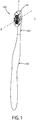
- FIG. 1 depicts one exemplary embodiment of a toothbrush 100 including a head 102 having a neck portion 101 and a handle 103 for grasping by a user.
- the handle 103 may be permanently or detachably coupled to the neck portion 101; the latter detachable handle example being suitable for a toothbrush having user-replaceable heads.
- the handle 103 is generally elongated in shape and may have any suitable ergonomic and aesthetically pleasing configuration dimensioned to gripped by a user.
- the handle 103 may be formed of one or more suitable materials conventionally used in the art for toothbrush handles including without limitation polymers, rubber, thermoplastic elastomers (TPE), and combinations thereof. Accordingly, the handle 103 may be formed with many different shapes, lengths, and varieties of constructions.
- the handle 103 may form part of a battery-operated toothbrush and include a power source and electric/electronic components.
- the handle 103 may have a reservoir containing an oral care material for dispensing into the oral cavity of a user. Accordingly, the toothbrush head 102 is not limited in its application to either manual or battery-operated toothbrushes alone.
- the toothbrush head 102 includes a front brushing side 104, an opposing rear side 105, two opposing lateral sides 106, 107, a distal end 108, and a proximal end 109 closest to the handle 103.
- a primary oral care region 110 is defined on the front brushing side 104 between the lateral sides 106 and 107, the distal end 108, and the proximal end 109.
- the rear side 105 may define a secondary oral care region 111 supporting a soft tissue cleaner and/or other ancillary tooth or soft tissue cleaning elements (not shown).
- the toothbrush head 102 may have an elongated elliptical or oval shape in one possible embodiment.
- the neck portion 101 may be tapered and narrower in width than the head 102 to smoothly transition into the handle 103.
- an imaginary X-Y-Z coordinate system is identified with respect to the toothbrush head 102 for ease of reference in describing the tooth cleaning elements 120.
- a horizontal plane and direction is defined by the X-Y axes (generally parallel to front brushing side 104 of toothbrush head 102) and vertical planes and directions are defined by the X-Z and Y-Z axes (generally perpendicular to the front brushing side 104 of the toothbrush head 102).
- the toothbrush head 102 has a longitudinal axis LA generally coinciding with the Y axis and a transverse axis TA perpendicular thereto coinciding with the X axis and positioned midway between the distal end 108 and the proximal end 109. This divides the oral care region 110 into a proximal treatment half P and distal treatment half D (shown in FIG. 3 ).
- the front side 104 of the oral care region 110 supports a plurality and variety of tooth cleaning elements 120 which extend from the toothbrush head 102.
- the tooth cleaning elements 120 may include a variety of bristle and elastomeric elements. It should be noted that the bristle tufts or elements in the drawings are illustrated in block form without the individual bristle strands being detailed for convenience and clarity so as to not obscure the structure of the bristle elements described herein. As shown in FIG.
- an imaginary nominal reference brushing plane BP is roughly defined by the tops/free ends of the tooth cleaning elements 120 which is offset from and approximately parallel to the longitudinal axis LA and the front brushing side 104 of the toothbrush head 102 (with variation allowing for varying heights of the cleaning elements 120).
- the tooth cleaning elements 120 will now each be described in greater detail.
- the tooth cleaning elements 120 include at least one tooth polishing unit 130.
- at least two polishing units 130 are provided as shown which may be considered a distal polishing unit and a proximal polishing unit located on either side of the transverse axis TA, as further described herein.
- the polishing unit 130 is shown schematically in dashed lines in FIG. 3 to show relative position with respect to other tooth cleaning elements to be described herein.
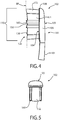
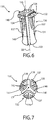
- FIGS. 6 and 7 show a perspective and top view of the polishing unit 130 disembodied from the toothbrush head 102 for clarity.
- the polishing unit 130 includes a resilient/flexible elastomeric tooth polishing element 136 and a bristle element 140 disposed at least partially therein.
- the polishing element 136 includes an elongated supporting shaft or base 131 and a relatively flattened polishing head 132 disposed on top of the base 131.
- the supporting base has a generally but not necessarily precisely columnar or cylindrical shape in configuration.
- the polishing head 132 is preferably horizontally broadened in the X-Y plane with respect to the supporting base 131.
- the polishing head 132 has a larger horizontal width or diameter than the adjoining supporting base 131 as measured in a plane generally parallel to the front side 104 of the toothbrush head 102.
- the supporting base 131 extends vertically downwards from the polishing head 132 to the toothbrush head 102 and includes a fixed anchoring end 133 which may be attached to front side 104 of toothbrush head 102 by any suitable means conventionally used in the art, including, but not limited to anchor-free tufting (AFT), in mold tufting (IFT), and stapled/anchored.
- AFT anchor-free tufting
- IFT in mold tufting
- the polishing element 136 may have a generally mushroom or umbrella like shape in side view (e.g. T-shaped side cross section) wherein the supporting base 131 is narrower in lateral width than the polishing head 132.
- this arrangement maximizes the area of polishing surface 135 while providing a flexible attachment to toothbrush head 102 with the narrow supporting base 131.
- the polishing head 132 extends horizontally and radially outwards from supporting base 131 and generally perpendicular to a vertical axis VA defined by the supporting base (see FIG. 6 ).
- the polishing head 132 forms a generally round or circular shape (in top view as best shown in FIGS. 3 and 7 ) and defines a polishing surface 135 for engaging and cleaning the teeth.
- the circular shape of the polishing head 132 and the polishing surface 135 advantageously provides multi-directional cleaning and polishing action on the teeth regardless of which brushing direction the user chooses to employ.
- the elastomeric polishing element 136 may be formed of any suitable flexible and resilient material having a shape memory that are conventionally used in the art for making elastomeric toothbrush elements.
- the polishing element 136 may be made of rubber or TPE.
- the polishing member 136 including supporting shaft or base 131 and polishing head 132 are formed as integral parts of a unitary elastomeric structure which may be molded such as by injection molding in a single step in a conventional manner.
- the polishing head 132 may be molded separately and attached to supporting base 131. Accordingly, the invention is not limited to either construction.
- the tooth polishing element 136 may be a single unitary elastomeric structure formed with slits or slots to accommodate a bristle element 140, or in a preferred embodiment may be comprised of two or more separate individual polishing members 137 that may be assembled and arranged in spaced but generally close proximity to collectively form the polishing element 136 and the polishing head 132, as best shown in FIGS. 2 , 3 , 6, and 7 .
- the polishing members 137 may each be formed of the same exemplary type of materials and constructed in a similar manner to the polishing element 136 described above.
- the polishing members 137 are spaced sufficiently to receive at least a portion of a bristle element such as element 140 described herein which may be interspersed between the polishing members.
- the polishing head 132 need not define a continuous circumferential edge in a preferred embodiment, but instead may be interrupted by gaps or slots in some embodiments when the polishing element 136 is comprised of two or more separate polishing members 137.
- a bristle element is disposed between at least one pair of polishing members 137.
- the tooth polishing element 136 may include three elastomeric tooth polishing members 137 as best shown in FIGS. 6 and 7 .
- the tooth polishing members 137 are arranged proximate to each other and concentrically around a central point CP in spaced relation to each other on the toothbrush head 102 to accommodate bristle elements therebetween as describe above.
- the polishing members 137 in one embodiment preferably have an inverted L-shape each with a supporting shaft or base 131 being anchored to toothbrush head 102 via anchoring end 133.
- the anchoring end 133 may be widened with respect to upper vertical portions of the supporting base 131 near the adjoining polishing head 132 to provide secure yet flexible fixation of the polishing member 137 to the head 102.
- the horizontally extending polishing head 132 (i.e. the shorter horizontal portion of the inverted "L" shape) of each polishing member 137 may have a wedge or fan-like shape in planar extent (i.e. when viewed in a horizontal plane from top).
- the wedge-shaped polishing heads 132 of each polishing member 137 define circumferentially spaced sectors of a circle in some embodiments with each head having an arcuate outer cleaning edge 138 and two converging lateral or side cleaning edges 139 disposed at an angle to each other which join at common point of origin O positioned circumferentially around and proximate to central point CP (best shown in FIG. 7 ).
- the wedge-shaped polishing heads 132 are preferably arranged to collectively form or approximate a generally circular but circumferentially discontinuous polishing surface 135 providing slots 141 for receiving the bristle element 140.
- the polishing heads 132 of polishing members 137 have a generally lateral or horizontal orientation (i.e. in the X-Y plane) extending generally parallel to brushing plan BP and front surface 104 of toothbrush head 102 in one embodiment. Accordingly, the polishing head 132 is angularly disposed on each polishing member 137 with respect to the adjoining vertically-oriented supporting base 131. Each polishing head 132 of the polishing members 137 is preferably further oriented to extend radially outwards and away from central point CP with the supporting base 131 of each polishing member being concentrically clustered around central point CP of the polishing unit 130.
- each polishing head 132 may be slightly angled upwards in a direction away from point CP in lieu of being parallel to the front surface 104 of the toothbrush head 102 with the arcuate outer cleaning edge 138 being located at a higher elevation than the portion of the polishing head 132 that transitions into the upper transition section T of the supporting base 131 (further described below).
- the resilient elastomeric polishing head 132 will tend to flatten. In that embodiment, therefore, the angle formed between the polishing head 132 and the adjoining supporting base 131 may be greater than 90 degrees. In other possible embodiments, the angle formed between the polishing head 132 and the adjoining supporting base 131 may be approximately 90 degrees or less than 90 degrees.
- FIGS. 9-10 show lateral horizontal cross sections taken from FIG. 8 respectively through the polishing head 132 and a transition section T of the supporting base 131 immediately below the polishing head 132.
- the transition section T may be shaped as an arcuate segment as shown in FIG. 10 .
- the supporting base 131 preferably has a smaller cross-sectional area than the polishing head 132 to enhance the flexibility of the supporting base and the polishing head 132 while maximizing the available polishing surface area of the polishing surface 135 to provide enhanced polishing and cleaning action.
- the polishing head 132 may include a plurality of elongated and spaced apart lamellas or ribs 134 to provide enhanced cleaning and polishing action.
- the ribs 134 are disposed on and extend upwards from the polishing surface 135 and in one exemplary embodiment may be arranged parallel to each other.
- the ribs 134 may be oriented as best shown in FIG. 7 to extend radially outwards from central point CP.
- the ribs 134 extend from the top polishing surface 135 over and onto the outward facing arcuate outer cleaning edge 138 of the polishing head 132 as best shown in FIGS. 8 and 9 .
- the supporting base 131 may also include ribs 134 configured and arranged similarly to the ribs 134 on the polishing head 132.
- the ribs 134 on supporting base 131 preferably are disposed on an outward facing surface of the base and extending in a direction generally away from the central point CP.
- the ribs 134 on the supporting base 131 need not extend downwards from the polishing head 132 all the way to the anchoring end 133 of the supporting base.
- the ribs 134 preferably extend at least partially downwards from the polishing head 132 along the height of the supporting base 131 far enough to cover the active cleaning and polishing zone of the polishing member 137 that engages the teeth which will generally be limited to the upper portions of the polishing member.
- the bristle element 140 is preferably disposed at least partially inside the polishing element 136.
- the bristle element 140 has a generally vertical orientation in an exemplary embodiment extending upwards from the front brushing side 104.
- the polishing head 132 and the polishing surface 135 defined thereon extend angularly and horizontally outwards from the bristle element 140 as best shown in FIGS. 6 and 7 .
- the polishing head 132 extends outwards at approximately 90 degrees to the bristle element 140.
- the polishing unit 130 defines a slot 141 which is configured and adapted to generally conform to the shape of the bristle element 140 received at least partially therein.
- the bristle element 140 in one exemplary embodiment may be Y-shaped (in lateral horizontal cross section); however, other suitable shapes of the bristle element 140 may be used.
- the bristle element 140 may have an X shape or five-point star shape and be constructed similarly to the polishing unit 130 already described herein having individual polishing members 137 interspersed between the legs of these shapes to form a generally circular polishing head 132 as described herein. Accordingly, it is well within the ambit of those skilled in the art to create these additional bristle element shapes using the principles and embodiments described herein without undue experimentation or description.
- the bristle element 140 crosses through and is located at the central point CP, and more preferably in one embodiment the intersection of all three legs 142 of the Y may coincide with the central point CP (see FIG. 7 ).
- all three legs 142 may be of equal length (measured in lateral horizontal cross section) and one of the legs is axially aligned with longitudinal axis LA. In other embodiments, legs 142 need not have the same length.
- each polishing member is preferably disposed between a pair of legs 142 of the bristle element 140 as shown. In one embodiment, the bristle element 140 extends vertically above the polishing element 136.
- polishing unit 130 may have more or less polishing members 137 and other shaped bristle elements 140. Accordingly, the invention is not limited to the exemplary embodiments shown herein.
- the polishing unit 130 is preferably centrally positioned in one embodiment between the lateral sides 106, 107 and along the longitudinal axis LA of the toothbrush head 102.
- the two axially aligned polishing units 130 may be provided with one unit being disposed between the transverse axis TA and the distal end 108 and another unit being disposed between the transverse axis TA and the proximal end 109.
- at least one of the legs 142 of the bristle element 140 is axially aligned with the longitudinal axis LA of the toothbrush head 102 with the remaining two legs 142 being angled with respect to the axis LA as best shown in FIG. 3 .
- the legs 142 may have other orientations.
- the polishing unit 130 essentially forms a disc-shaped polishing pad for cleaning and polishing the teeth which when accompanied by use of a dentifrice have whitening agents is intended to provide more effective stain removal and whitening action.
- the generally flattened polishing heads 132 of the polishing members 137 further serve to provide a platform for supporting dentifrice during brushing and reducing migration of dentifrice downwards between the bristles towards the front surface 104 of the toothbrush head 102 for more effective polishing, cleaning, and whitening action.
- the polishing unit 130 is preferably at least partially surrounded by additional bristle elements that flank the circumferential sides of the polishing unit.
- additional bristle elements that flank the circumferential sides of the polishing unit.
- at least two and more preferably three arcuate tooth cleaning bristle elements 170 are provided each having a concave inner side that faces and partially surrounds polishing unit 130.
- Each arcuate bristle element 170 is formed of a tuft of bristles made of any suitable bristle material conventionally used in the art.
- the arcuate bristle elements 170 may include a pair of transversely spaced apart lateral side arcuate elements 171 with one each located adjacent polishing unit 130 near the peripheral edges and the lateral sides 106 and 107 of the toothbrush head 102, and further a third single arcuate axial distal or proximal element 172 positioned along the longitudinal axis LA of the head 102. As best shown in FIG.
- one axial distal element 172 is preferably located near the distal end 108 of the toothbrush head 102 (forward of the distal tooth polishing unit 130) and another axial proximal element 172 is preferably located near the proximal end 109 of the toothbrush head 102 (rearward of the proximal tooth polishing unit 130 towards the handle 103).
- the lateral and axial bristle elements 171, 172 are positioned symmetrically with respect to the longitudinal axis LA as shown in FIG. 3 . In other possible arrangements, asymmetrical positioning of the bristle elements 171, 172 may be used.
- the proximal and/or distal axial bristle elements 172 may be angled or slants such that the height of bristles preferably slopes in a longitudinal upwards direction away from transverse axis TA and towards the distal end 108 and the proximal end 109 of the toothbrush head 102, respectively, as best shown in FIG. 4 .
- the angled arrangement of the axial bristle elements 172 enhances the reach and cleaning of these bristle tufts.
- the lateral side arcuate elements 171 may also be slanted or angled upwards in a longitudinal direction away from transverse axis TA and the proximal or distal ends 108, 109 of the toothbrush head 102.
- the polishing units 130 may have a vertical height with respect to the arcuate bristle elements 170 such that that tops of the Y-shaped bristle element 140 is approximately even with the lowest portions of the lateral side arcuate elements 170 and the polishing head 132 of the polishing element 136 is positioned vertically to be slightly below the bristle element 140 and the lowest portions of the lateral side arcuate elements 170. It will be appreciated that other arrangements are possible with respect to the height of the polishing unit 130 and the lateral side arcuate elements 170.
- the toothbrush head 102 further includes a pair of intermediate tooth cleaning bristle elements 150 which are laterally spaced apart along the transverse axis TA in one preferred embodiment.
- Each intermediate bristle element is preferably positioned between the longitudinal axis LA and the lateral sides 106 and 107 respectively, and more preferably is positioned between the longitudinal axis LA and the deep cleaning elements 160 as further described herein.
- intermediate bristle elements 150 may be located each side of the longitudinal axis LA with one element each being positioned approximately at or near the midpoint between the axis LA and the lateral sides 106 and 107, respectively, as shown.
- the intermediate bristle elements 150 may be formed as arcuately-shaped elements (in lateral horizontal cross section) with a concave portion facing inwards toward the longitudinal axis LA.
- the bristle elements 150 are configured to complement and fit the shape of the gap created between vdeep cleaning bristle elements 160 and the bristle elements 170 as best shown in FIG. 3 .
- These intermediate bristle elements 150 may be comprised of a tuft of bristles formed of any suitable material conventionally used in the art.
- a plurality of combination side cleaning elements such as deep cleaning bristle elements 160 in one embodiment are provided on toothbrush head 102.
- the deep cleaning bristle elements 160 efficiently combine vertically higher/taller deep cleaning bristle structures with lower regular height conventional cleaning bristles in a single bristle tuft to conserve the limited space available on front surface 104 of the toothbrush head 102 as further explained.
- the deep cleaning bristle elements 160 may be formed in part by a tuft of conventional cleaning bristles 167 having a tear drop or cam shape (in lateral horizontal cross section) as best shown in FIG. 12 , with a relatively stiffer and broad end portion 161 and an opposite narrow more flexible end portion 162.
- the conventional bristles 167 have a relatively uniform vertical height and form a top bristle surface 163 defined by the tips of the bristles.
- the broad end portion 161 of the deep cleaning bristle elements 160 preferably includes a cylindrically-shaped deep cleaning projection 164 which rises and extends vertically above adjacent portions of top bristle surface 163 formed by the cleaning bristles 167 (best shown in FIG. 11 ).
- the cleaning projection 164 may be comprised of one or more concentrically aligned cylindrical deep cleaning bristle tufts 165 and 166 as shown which are intended to cleanse the tooth area adjacent the gums and gaps between teeth.
- the bristle tufts 165 and 166 form a tiered or stepped cleaning structure as best shown in FIG. 11 with the central tuft 166 being vertically higher/taller than the outer bristle tuft 165.
- At least one and preferably two deep cleaning bristle elements 160 are disposed proximate to the lateral sides 106 and 107 of the toothbrush head 102 and the transverse axis TA towards the longitudinal center of the toothbrush head.
- a pair of deep cleaning bristle elements 160 are disposed near each lateral side 106, 107 with a deep cleaning bristle element positioned on either side of axis TA and outboard of the intermediate tooth cleaning bristle elements 150. It will be appreciated that additional deep cleaning bristle elements 160 and/or other arrangements are possible.
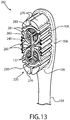
- FIGS. 13 and 14 show an alternative embodiment of a toothbrush head 202 whose structure may be configured similarly to toothbrush head 102 as shown.
- the toothbrush head 202 incorporates some of the same tooth cleaning elements 120 described herein with a modified arrangement of some of the cleaning elements and adds other new elements.
- the toothbrush head 202 includes two polishing units 230 comprised of individual polishing members 137 similar to those described herein and a bristle element 240 having a similar, but slightly modified configuration and orientation than bristle element 140.
- the bristle element 140 which preferably has three legs 142 of even length in the embodiment shown in FIG. 7 (measured in a horizontal plane parallel to front surface 104 of toothbrush head 102), one leg 242 of the bristle element 240 is longer than the remaining two shorter legs 243.
- the longer leg 242 is preferably axially aligned with the longitudinal axis LA and extends out of the Y-shaped slot 241 and laterally beyond the polishing members 137 as best shown in FIG. 14 .
- the two shorter legs are disposed at an angle to both the longitudinal axis LA and the transverse axis TA as shown.
- the two longer legs 242 of each bristle element 240 are arranged in confronting relationship to each other along the longitudinal axis LA as shown but do not meet or touch leaving a small gap therebetween the ends of the legs.
- the longer legs 242 of each bristle element 240 may meet to interconnect both bristle elements 240.
- the toothbrush head 202 further includes two distal arcuate tooth cleaning bristle elements 270 and two proximal arcuate tooth cleaning bristle elements 270 configured and structured similarly to arcuate tooth cleaning bristle elements 170 described herein elsewhere.
- a plurality of deep cleaning bristle elements 260 similar in configuration and structure to the deep cleaning bristle elements 160 described are also provided on the toothbrush head 202.
- a cluster of deep cleaning elements 260 are disposed proximate to lateral sides 106 and 107 of toothbrush head 202 and transverse axis TA towards the center of the toothbrush head.
- each cam-shaped bristle element 260 preferably faces inwards towards longitudinal axis LA whereas in the toothbrush head 102 by comparison the narrow portion is preferably oriented towards transverse axis TA (see, e.g. FIG. 3 ).
- each polishing unit 230 is at least partially surrounded by three circumferentially-oriented and segmented arcuate tooth cleaning bristle elements 280 (in lateral horizontal cross section).
- the arcuate bristle elements 280 are circumferentially spaced apart as shown and form a ring-shaped bristle element around polishing unit 230.
- Each bristle element 280 segment may include one or more flanged portions 281 (also formed of bristles preferably) that extend radially and laterally outwards from the polishing units 230.
- some or all of the arcuate bristle elements 280 may not be provided with any flanged portions 281 similar to some elements shown.
- FIGS. 13 and 14 show two exemplary possible flanged portion 281 variations and therefore each bristle element 280 in these two figures may be similar but not necessarily identical in configuration.
- the tooth cleaning elements described herein may be attached to the toothbrush head by any suitable conventional method used in the art such as, without limitation for example, anchor free tufting (AFT), in mold tufting, anchor/staple, injection molding, ultrasonic welding, and combinations thereof.
- AFT anchor free tufting
- features of the exemplary embodiments described herein may be practiced and incorporated in manual or powered toothbrushes.
Landscapes
- Brushes (AREA)
Applications Claiming Priority (1)
| Application Number | Priority Date | Filing Date | Title |
|---|---|---|---|
| PCT/US2010/022557 WO2011093874A1 (en) | 2010-01-29 | 2010-01-29 | Oral care implement |
Publications (2)
| Publication Number | Publication Date |
|---|---|
| EP2528470A1 EP2528470A1 (en) | 2012-12-05 |
| EP2528470B1 true EP2528470B1 (en) | 2017-08-02 |
Family
ID=42735348
Family Applications (1)
| Application Number | Title | Priority Date | Filing Date |
|---|---|---|---|
| EP10702216.2A Active EP2528470B1 (en) | 2010-01-29 | 2010-01-29 | Oral care implement |
Country Status (12)
| Country | Link |
|---|---|
| US (2) | US8732889B2 (pt) |
| EP (1) | EP2528470B1 (pt) |
| KR (1) | KR101356822B1 (pt) |
| CN (1) | CN103025199B (pt) |
| AU (1) | AU2010344205B2 (pt) |
| BR (1) | BR112012017607A2 (pt) |
| CA (1) | CA2787023C (pt) |
| IN (1) | IN2012DN05917A (pt) |
| MX (1) | MX2012008228A (pt) |
| RU (1) | RU2523986C2 (pt) |
| TW (1) | TWI458451B (pt) |
| WO (1) | WO2011093874A1 (pt) |
Families Citing this family (11)
| Publication number | Priority date | Publication date | Assignee | Title |
|---|---|---|---|---|
| WO2012040146A2 (en) | 2010-09-20 | 2012-03-29 | The Gillette Company | Force sensing oral care instrument |
| US8769758B2 (en) | 2010-09-20 | 2014-07-08 | The Gillette Company | Force sensing oral care instrument |
| KR200470751Y1 (ko) * | 2012-11-13 | 2014-01-09 | (주)아모레퍼시픽 | 구강 관리 칫솔 |
| KR200470752Y1 (ko) * | 2012-11-13 | 2014-01-09 | (주)아모레퍼시픽 | 구강 관리 칫솔 |
| KR200470753Y1 (ko) * | 2012-11-13 | 2014-01-09 | (주)아모레퍼시픽 | 구강 관리 칫솔 |
| ES2874477T3 (es) * | 2014-07-11 | 2021-11-05 | Procter & Gamble | Cabezal para un utensilio de cuidado bucal |
| CN204812617U (zh) | 2015-03-27 | 2015-12-02 | 高露洁-棕榄公司 | 牙刷 |
| AU364694S (en) | 2015-03-27 | 2015-10-14 | Colgate Palmolive Co | Oral care implement |
| WO2018134270A1 (en) | 2017-01-23 | 2018-07-26 | Unilever Plc | A toothbrush |
| US10674808B2 (en) * | 2018-03-23 | 2020-06-09 | Colgate-Palmolive Company | Oral care implement and method of forming the same |
| CN116456866A (zh) * | 2020-11-17 | 2023-07-18 | 高露洁-棕榄公司 | 具有流体分配系统的口腔护理器具 |
Family Cites Families (11)
| Publication number | Priority date | Publication date | Assignee | Title |
|---|---|---|---|---|
| US1268544A (en) * | 1918-04-12 | 1918-06-04 | Lorwin N Cates | Tooth-brush. |
| DE10164336A1 (de) * | 2001-12-28 | 2003-07-17 | Trisa Holding Ag Triengen | Zahnbürste und Verfahren zur Herstellung einer solchen Zahnbürste |
| US7975343B2 (en) | 2002-09-20 | 2011-07-12 | Colgate-Palmolive Company | Toothbrush |
| EP1555908A4 (en) * | 2002-09-27 | 2008-08-06 | Colgate Palmolive Co | TOOTHBRUSH FOR BETTER CLEANING |
| ATE508659T1 (de) | 2002-09-27 | 2011-05-15 | Colgate Palmolive Co | Zahnbürste |
| US6966093B2 (en) * | 2002-09-27 | 2005-11-22 | Colgate-Polmolive Company | Toothbrush having a movable upstanding cleaning element |
| US20040200016A1 (en) * | 2003-04-09 | 2004-10-14 | The Procter & Gamble Company | Electric toothbrushes |
| US20060080799A1 (en) * | 2004-10-18 | 2006-04-20 | Frank Lucente | Toothbrush featuring bristles with raised annular portions |
| MX2008003175A (es) * | 2005-09-09 | 2008-03-18 | Colgate Palmolive Co | Cepillo de dientes. |
| DE102006016939A1 (de) * | 2005-11-08 | 2007-05-24 | Synpart Ag | Zahnbürste |
| US8056176B2 (en) | 2007-01-25 | 2011-11-15 | The Procter & Gamble Company | Toothbrushes |
-
2010
- 2010-01-29 US US13/130,191 patent/US8732889B2/en not_active Expired - Fee Related
- 2010-01-29 WO PCT/US2010/022557 patent/WO2011093874A1/en active Application Filing
- 2010-01-29 RU RU2012136818/12A patent/RU2523986C2/ru not_active IP Right Cessation
- 2010-01-29 AU AU2010344205A patent/AU2010344205B2/en not_active Ceased
- 2010-01-29 MX MX2012008228A patent/MX2012008228A/es active IP Right Grant
- 2010-01-29 KR KR1020127022627A patent/KR101356822B1/ko not_active IP Right Cessation
- 2010-01-29 CN CN201080062569.0A patent/CN103025199B/zh not_active Expired - Fee Related
- 2010-01-29 EP EP10702216.2A patent/EP2528470B1/en active Active
- 2010-01-29 IN IN5917DEN2012 patent/IN2012DN05917A/en unknown
- 2010-01-29 CA CA2787023A patent/CA2787023C/en not_active Expired - Fee Related
- 2010-01-29 BR BR112012017607A patent/BR112012017607A2/pt not_active Application Discontinuation
-
2011
- 2011-01-28 TW TW100103226A patent/TWI458451B/zh not_active IP Right Cessation
-
2014
- 2014-05-27 US US14/288,357 patent/US9131766B2/en active Active
Non-Patent Citations (1)
| Title |
|---|
| None * |
Also Published As
| Publication number | Publication date |
|---|---|
| MX2012008228A (es) | 2012-08-03 |
| US20110289708A1 (en) | 2011-12-01 |
| WO2011093874A1 (en) | 2011-08-04 |
| KR101356822B1 (ko) | 2014-01-28 |
| CN103025199B (zh) | 2015-10-21 |
| CN103025199A (zh) | 2013-04-03 |
| US20140259485A1 (en) | 2014-09-18 |
| BR112012017607A2 (pt) | 2016-04-12 |
| US9131766B2 (en) | 2015-09-15 |
| AU2010344205B2 (en) | 2014-02-27 |
| CA2787023A1 (en) | 2011-08-04 |
| KR20120112844A (ko) | 2012-10-11 |
| AU2010344205A1 (en) | 2012-07-19 |
| EP2528470A1 (en) | 2012-12-05 |
| TWI458451B (zh) | 2014-11-01 |
| TW201141418A (en) | 2011-12-01 |
| US8732889B2 (en) | 2014-05-27 |
| CA2787023C (en) | 2015-04-07 |
| RU2012136818A (ru) | 2014-03-10 |
| RU2523986C2 (ru) | 2014-07-27 |
| IN2012DN05917A (pt) | 2015-09-18 |
Similar Documents
| Publication | Publication Date | Title |
|---|---|---|
| EP2528470B1 (en) | Oral care implement | |
| EP2710919B1 (en) | Oral care implement | |
| EP2515698B1 (en) | Oral care implement | |
| KR101441773B1 (ko) | 폐쇄된-루프 배치된 세척요소를 가진 칫솔 | |
| AU2014277704B2 (en) | Oral care implement | |
| CN105249670B (zh) | 口腔护理器具 |
Legal Events
| Date | Code | Title | Description |
|---|---|---|---|
| PUAI | Public reference made under article 153(3) epc to a published international application that has entered the european phase |
Free format text: ORIGINAL CODE: 0009012 |
|
| 17P | Request for examination filed |
Effective date: 20120716 |
|
| AK | Designated contracting states |
Kind code of ref document: A1 Designated state(s): AT BE BG CH CY CZ DE DK EE ES FI FR GB GR HR HU IE IS IT LI LT LU LV MC MK MT NL NO PL PT RO SE SI SK SM TR |
|
| DAX | Request for extension of the european patent (deleted) | ||
| REG | Reference to a national code |
Ref country code: HK Ref legal event code: DE Ref document number: 1178403 Country of ref document: HK |
|
| GRAP | Despatch of communication of intention to grant a patent |
Free format text: ORIGINAL CODE: EPIDOSNIGR1 |
|
| STAA | Information on the status of an ep patent application or granted ep patent |
Free format text: STATUS: GRANT OF PATENT IS INTENDED |
|
| INTG | Intention to grant announced |
Effective date: 20170227 |
|
| GRAS | Grant fee paid |
Free format text: ORIGINAL CODE: EPIDOSNIGR3 |
|
| GRAA | (expected) grant |
Free format text: ORIGINAL CODE: 0009210 |
|
| STAA | Information on the status of an ep patent application or granted ep patent |
Free format text: STATUS: THE PATENT HAS BEEN GRANTED |
|
| AK | Designated contracting states |
Kind code of ref document: B1 Designated state(s): AT BE BG CH CY CZ DE DK EE ES FI FR GB GR HR HU IE IS IT LI LT LU LV MC MK MT NL NO PL PT RO SE SI SK SM TR |
|
| REG | Reference to a national code |
Ref country code: GB Ref legal event code: FG4D |
|
| RIN1 | Information on inventor provided before grant (corrected) |
Inventor name: ROONEY, MICHAEL Inventor name: GATZEMEYER, JOHN Inventor name: KLAUSEGGER, RAIMUND Inventor name: JIMENEZ, EDUARDO Inventor name: MOSKOVICH, ROBERT Inventor name: STORZ, JOACHIM Inventor name: KENNEDY, SHARON |
|
| REG | Reference to a national code |
Ref country code: CH Ref legal event code: EP Ref country code: AT Ref legal event code: REF Ref document number: 913484 Country of ref document: AT Kind code of ref document: T Effective date: 20170815 |
|
| REG | Reference to a national code |
Ref country code: IE Ref legal event code: FG4D |
|
| REG | Reference to a national code |
Ref country code: DE Ref legal event code: R096 Ref document number: 602010044027 Country of ref document: DE |
|
| REG | Reference to a national code |
Ref country code: NL Ref legal event code: MP Effective date: 20170802 |
|
| REG | Reference to a national code |
Ref country code: AT Ref legal event code: MK05 Ref document number: 913484 Country of ref document: AT Kind code of ref document: T Effective date: 20170802 |
|
| REG | Reference to a national code |
Ref country code: LT Ref legal event code: MG4D |
|
| REG | Reference to a national code |
Ref country code: FR Ref legal event code: PLFP Year of fee payment: 9 |
|
| PG25 | Lapsed in a contracting state [announced via postgrant information from national office to epo] |
Ref country code: NO Free format text: LAPSE BECAUSE OF FAILURE TO SUBMIT A TRANSLATION OF THE DESCRIPTION OR TO PAY THE FEE WITHIN THE PRESCRIBED TIME-LIMIT Effective date: 20171102 Ref country code: HR Free format text: LAPSE BECAUSE OF FAILURE TO SUBMIT A TRANSLATION OF THE DESCRIPTION OR TO PAY THE FEE WITHIN THE PRESCRIBED TIME-LIMIT Effective date: 20170802 Ref country code: SE Free format text: LAPSE BECAUSE OF FAILURE TO SUBMIT A TRANSLATION OF THE DESCRIPTION OR TO PAY THE FEE WITHIN THE PRESCRIBED TIME-LIMIT Effective date: 20170802 Ref country code: FI Free format text: LAPSE BECAUSE OF FAILURE TO SUBMIT A TRANSLATION OF THE DESCRIPTION OR TO PAY THE FEE WITHIN THE PRESCRIBED TIME-LIMIT Effective date: 20170802 Ref country code: AT Free format text: LAPSE BECAUSE OF FAILURE TO SUBMIT A TRANSLATION OF THE DESCRIPTION OR TO PAY THE FEE WITHIN THE PRESCRIBED TIME-LIMIT Effective date: 20170802 Ref country code: LT Free format text: LAPSE BECAUSE OF FAILURE TO SUBMIT A TRANSLATION OF THE DESCRIPTION OR TO PAY THE FEE WITHIN THE PRESCRIBED TIME-LIMIT Effective date: 20170802 Ref country code: NL Free format text: LAPSE BECAUSE OF FAILURE TO SUBMIT A TRANSLATION OF THE DESCRIPTION OR TO PAY THE FEE WITHIN THE PRESCRIBED TIME-LIMIT Effective date: 20170802 |
|
| PG25 | Lapsed in a contracting state [announced via postgrant information from national office to epo] |
Ref country code: GR Free format text: LAPSE BECAUSE OF FAILURE TO SUBMIT A TRANSLATION OF THE DESCRIPTION OR TO PAY THE FEE WITHIN THE PRESCRIBED TIME-LIMIT Effective date: 20171103 Ref country code: ES Free format text: LAPSE BECAUSE OF FAILURE TO SUBMIT A TRANSLATION OF THE DESCRIPTION OR TO PAY THE FEE WITHIN THE PRESCRIBED TIME-LIMIT Effective date: 20170802 Ref country code: BG Free format text: LAPSE BECAUSE OF FAILURE TO SUBMIT A TRANSLATION OF THE DESCRIPTION OR TO PAY THE FEE WITHIN THE PRESCRIBED TIME-LIMIT Effective date: 20171102 Ref country code: IS Free format text: LAPSE BECAUSE OF FAILURE TO SUBMIT A TRANSLATION OF THE DESCRIPTION OR TO PAY THE FEE WITHIN THE PRESCRIBED TIME-LIMIT Effective date: 20171202 Ref country code: PL Free format text: LAPSE BECAUSE OF FAILURE TO SUBMIT A TRANSLATION OF THE DESCRIPTION OR TO PAY THE FEE WITHIN THE PRESCRIBED TIME-LIMIT Effective date: 20170802 Ref country code: LV Free format text: LAPSE BECAUSE OF FAILURE TO SUBMIT A TRANSLATION OF THE DESCRIPTION OR TO PAY THE FEE WITHIN THE PRESCRIBED TIME-LIMIT Effective date: 20170802 |
|
| PG25 | Lapsed in a contracting state [announced via postgrant information from national office to epo] |
Ref country code: RO Free format text: LAPSE BECAUSE OF FAILURE TO SUBMIT A TRANSLATION OF THE DESCRIPTION OR TO PAY THE FEE WITHIN THE PRESCRIBED TIME-LIMIT Effective date: 20170802 Ref country code: CZ Free format text: LAPSE BECAUSE OF FAILURE TO SUBMIT A TRANSLATION OF THE DESCRIPTION OR TO PAY THE FEE WITHIN THE PRESCRIBED TIME-LIMIT Effective date: 20170802 Ref country code: DK Free format text: LAPSE BECAUSE OF FAILURE TO SUBMIT A TRANSLATION OF THE DESCRIPTION OR TO PAY THE FEE WITHIN THE PRESCRIBED TIME-LIMIT Effective date: 20170802 |
|
| REG | Reference to a national code |
Ref country code: DE Ref legal event code: R097 Ref document number: 602010044027 Country of ref document: DE |
|
| PG25 | Lapsed in a contracting state [announced via postgrant information from national office to epo] |
Ref country code: EE Free format text: LAPSE BECAUSE OF FAILURE TO SUBMIT A TRANSLATION OF THE DESCRIPTION OR TO PAY THE FEE WITHIN THE PRESCRIBED TIME-LIMIT Effective date: 20170802 Ref country code: SM Free format text: LAPSE BECAUSE OF FAILURE TO SUBMIT A TRANSLATION OF THE DESCRIPTION OR TO PAY THE FEE WITHIN THE PRESCRIBED TIME-LIMIT Effective date: 20170802 Ref country code: IT Free format text: LAPSE BECAUSE OF FAILURE TO SUBMIT A TRANSLATION OF THE DESCRIPTION OR TO PAY THE FEE WITHIN THE PRESCRIBED TIME-LIMIT Effective date: 20170802 Ref country code: SK Free format text: LAPSE BECAUSE OF FAILURE TO SUBMIT A TRANSLATION OF THE DESCRIPTION OR TO PAY THE FEE WITHIN THE PRESCRIBED TIME-LIMIT Effective date: 20170802 |
|
| PLBE | No opposition filed within time limit |
Free format text: ORIGINAL CODE: 0009261 |
|
| STAA | Information on the status of an ep patent application or granted ep patent |
Free format text: STATUS: NO OPPOSITION FILED WITHIN TIME LIMIT |
|
| 26N | No opposition filed |
Effective date: 20180503 |
|
| PG25 | Lapsed in a contracting state [announced via postgrant information from national office to epo] |
Ref country code: SI Free format text: LAPSE BECAUSE OF FAILURE TO SUBMIT A TRANSLATION OF THE DESCRIPTION OR TO PAY THE FEE WITHIN THE PRESCRIBED TIME-LIMIT Effective date: 20170802 |
|
| PG25 | Lapsed in a contracting state [announced via postgrant information from national office to epo] |
Ref country code: LU Free format text: LAPSE BECAUSE OF NON-PAYMENT OF DUE FEES Effective date: 20180129 |
|
| REG | Reference to a national code |
Ref country code: IE Ref legal event code: MM4A |
|
| REG | Reference to a national code |
Ref country code: BE Ref legal event code: MM Effective date: 20180131 |
|
| PG25 | Lapsed in a contracting state [announced via postgrant information from national office to epo] |
Ref country code: BE Free format text: LAPSE BECAUSE OF NON-PAYMENT OF DUE FEES Effective date: 20180131 |
|
| PG25 | Lapsed in a contracting state [announced via postgrant information from national office to epo] |
Ref country code: IE Free format text: LAPSE BECAUSE OF NON-PAYMENT OF DUE FEES Effective date: 20180129 |
|
| PG25 | Lapsed in a contracting state [announced via postgrant information from national office to epo] |
Ref country code: MC Free format text: LAPSE BECAUSE OF FAILURE TO SUBMIT A TRANSLATION OF THE DESCRIPTION OR TO PAY THE FEE WITHIN THE PRESCRIBED TIME-LIMIT Effective date: 20170802 |
|
| PG25 | Lapsed in a contracting state [announced via postgrant information from national office to epo] |
Ref country code: MT Free format text: LAPSE BECAUSE OF NON-PAYMENT OF DUE FEES Effective date: 20180129 |
|
| PG25 | Lapsed in a contracting state [announced via postgrant information from national office to epo] |
Ref country code: TR Free format text: LAPSE BECAUSE OF FAILURE TO SUBMIT A TRANSLATION OF THE DESCRIPTION OR TO PAY THE FEE WITHIN THE PRESCRIBED TIME-LIMIT Effective date: 20170802 |
|
| PG25 | Lapsed in a contracting state [announced via postgrant information from national office to epo] |
Ref country code: HU Free format text: LAPSE BECAUSE OF FAILURE TO SUBMIT A TRANSLATION OF THE DESCRIPTION OR TO PAY THE FEE WITHIN THE PRESCRIBED TIME-LIMIT; INVALID AB INITIO Effective date: 20100129 Ref country code: PT Free format text: LAPSE BECAUSE OF FAILURE TO SUBMIT A TRANSLATION OF THE DESCRIPTION OR TO PAY THE FEE WITHIN THE PRESCRIBED TIME-LIMIT Effective date: 20170802 |
|
| PG25 | Lapsed in a contracting state [announced via postgrant information from national office to epo] |
Ref country code: CY Free format text: LAPSE BECAUSE OF FAILURE TO SUBMIT A TRANSLATION OF THE DESCRIPTION OR TO PAY THE FEE WITHIN THE PRESCRIBED TIME-LIMIT Effective date: 20170802 Ref country code: MK Free format text: LAPSE BECAUSE OF NON-PAYMENT OF DUE FEES Effective date: 20170802 |
|
| PGFP | Annual fee paid to national office [announced via postgrant information from national office to epo] |
Ref country code: FR Payment date: 20230125 Year of fee payment: 14 Ref country code: CH Payment date: 20230130 Year of fee payment: 14 |
|
| PGFP | Annual fee paid to national office [announced via postgrant information from national office to epo] |
Ref country code: GB Payment date: 20230127 Year of fee payment: 14 Ref country code: DE Payment date: 20230127 Year of fee payment: 14 |
|
| P01 | Opt-out of the competence of the unified patent court (upc) registered |
Effective date: 20230530 |