EP2528155A1 - Battery pack - Google Patents
Battery pack Download PDFInfo
- Publication number
- EP2528155A1 EP2528155A1 EP12169530A EP12169530A EP2528155A1 EP 2528155 A1 EP2528155 A1 EP 2528155A1 EP 12169530 A EP12169530 A EP 12169530A EP 12169530 A EP12169530 A EP 12169530A EP 2528155 A1 EP2528155 A1 EP 2528155A1
- Authority
- EP
- European Patent Office
- Prior art keywords
- terminal
- discharge
- charge
- unit
- battery
- Prior art date
- Legal status (The legal status is an assumption and is not a legal conclusion. Google has not performed a legal analysis and makes no representation as to the accuracy of the status listed.)
- Granted
Links
Images




Classifications
-
- H—ELECTRICITY
- H01—ELECTRIC ELEMENTS
- H01M—PROCESSES OR MEANS, e.g. BATTERIES, FOR THE DIRECT CONVERSION OF CHEMICAL ENERGY INTO ELECTRICAL ENERGY
- H01M10/00—Secondary cells; Manufacture thereof
- H01M10/04—Construction or manufacture in general
- H01M10/0445—Multimode batteries, e.g. containing auxiliary cells or electrodes switchable in parallel or series connections
-
- H—ELECTRICITY
- H01—ELECTRIC ELEMENTS
- H01M—PROCESSES OR MEANS, e.g. BATTERIES, FOR THE DIRECT CONVERSION OF CHEMICAL ENERGY INTO ELECTRICAL ENERGY
- H01M10/00—Secondary cells; Manufacture thereof
- H01M10/42—Methods or arrangements for servicing or maintenance of secondary cells or secondary half-cells
- H01M10/44—Methods for charging or discharging
-
- H—ELECTRICITY
- H01—ELECTRIC ELEMENTS
- H01M—PROCESSES OR MEANS, e.g. BATTERIES, FOR THE DIRECT CONVERSION OF CHEMICAL ENERGY INTO ELECTRICAL ENERGY
- H01M10/00—Secondary cells; Manufacture thereof
- H01M10/42—Methods or arrangements for servicing or maintenance of secondary cells or secondary half-cells
- H01M10/44—Methods for charging or discharging
- H01M10/441—Methods for charging or discharging for several batteries or cells simultaneously or sequentially
-
- H—ELECTRICITY
- H02—GENERATION; CONVERSION OR DISTRIBUTION OF ELECTRIC POWER
- H02J—ELECTRIC POWER NETWORKS; CIRCUIT ARRANGEMENTS OR SYSTEMS FOR SUPPLYING OR DISTRIBUTING ELECTRIC POWER; SYSTEMS FOR STORING ELECTRIC ENERGY
- H02J7/00—Circuit arrangements for charging or discharging batteries or for supplying loads from batteries
- H02J7/50—Circuit arrangements for charging or discharging batteries or for supplying loads from batteries acting upon multiple batteries simultaneously or sequentially
- H02J7/575—Parallel/serial switching of connection of batteries to charge or load circuit
-
- H—ELECTRICITY
- H01—ELECTRIC ELEMENTS
- H01M—PROCESSES OR MEANS, e.g. BATTERIES, FOR THE DIRECT CONVERSION OF CHEMICAL ENERGY INTO ELECTRICAL ENERGY
- H01M10/00—Secondary cells; Manufacture thereof
- H01M10/42—Methods or arrangements for servicing or maintenance of secondary cells or secondary half-cells
- H01M10/48—Accumulators combined with arrangements for measuring, testing or indicating the condition of cells, e.g. the level or density of the electrolyte
- H01M10/482—Accumulators combined with arrangements for measuring, testing or indicating the condition of cells, e.g. the level or density of the electrolyte for several batteries or cells simultaneously or sequentially
-
- H—ELECTRICITY
- H01—ELECTRIC ELEMENTS
- H01M—PROCESSES OR MEANS, e.g. BATTERIES, FOR THE DIRECT CONVERSION OF CHEMICAL ENERGY INTO ELECTRICAL ENERGY
- H01M10/00—Secondary cells; Manufacture thereof
- H01M10/42—Methods or arrangements for servicing or maintenance of secondary cells or secondary half-cells
- H01M10/425—Structural combination with electronic components, e.g. electronic circuits integrated to the outside of the casing
- H01M2010/4271—Battery management systems including electronic circuits, e.g. control of current or voltage to keep battery in healthy state, cell balancing
-
- Y—GENERAL TAGGING OF NEW TECHNOLOGICAL DEVELOPMENTS; GENERAL TAGGING OF CROSS-SECTIONAL TECHNOLOGIES SPANNING OVER SEVERAL SECTIONS OF THE IPC; TECHNICAL SUBJECTS COVERED BY FORMER USPC CROSS-REFERENCE ART COLLECTIONS [XRACs] AND DIGESTS
- Y02—TECHNOLOGIES OR APPLICATIONS FOR MITIGATION OR ADAPTATION AGAINST CLIMATE CHANGE
- Y02E—REDUCTION OF GREENHOUSE GAS [GHG] EMISSIONS, RELATED TO ENERGY GENERATION, TRANSMISSION OR DISTRIBUTION
- Y02E60/00—Enabling technologies; Technologies with a potential or indirect contribution to GHG emissions mitigation
- Y02E60/10—Energy storage using batteries
-
- Y—GENERAL TAGGING OF NEW TECHNOLOGICAL DEVELOPMENTS; GENERAL TAGGING OF CROSS-SECTIONAL TECHNOLOGIES SPANNING OVER SEVERAL SECTIONS OF THE IPC; TECHNICAL SUBJECTS COVERED BY FORMER USPC CROSS-REFERENCE ART COLLECTIONS [XRACs] AND DIGESTS
- Y02—TECHNOLOGIES OR APPLICATIONS FOR MITIGATION OR ADAPTATION AGAINST CLIMATE CHANGE
- Y02P—CLIMATE CHANGE MITIGATION TECHNOLOGIES IN THE PRODUCTION OR PROCESSING OF GOODS
- Y02P70/00—Climate change mitigation technologies in the production process for final industrial or consumer products
- Y02P70/50—Manufacturing or production processes characterised by the final manufactured product
Definitions
- the present invention relates to a battery pack.
- Rechargeable secondary batteries are used as portable power sources for portable electronic equipment such as cellular phones, notebook computers, camcorders, personal digital assistants (PDA), and home appliances such as a vacuum cleaner.
- portable electronic equipment such as cellular phones, notebook computers, camcorders, personal digital assistants (PDA), and home appliances
- PDA personal digital assistants
- a vacuum cleaner In a general home vacuum cleaner, a motor of the vacuum cleaner is driven using AC power in the home.
- a separate power source is necessary.
- the secondary battery used as a portable power source has different capacities according to the specification and high capacity power of approximately 100 V or higher is generally required to be used as the separate power source.
- Embodiments of the invention seek to provide a battery pack for achieving high-efficiency charging and high-power discharging.
- a battery pack comprising: a battery module comprising a plurality of battery units, each battery unit being provided with respective electrode terminals; and a control unit for providing a first configuration in which the plurality of battery units are connected in series for discharging the battery module, and a second configuration in which the plurality of battery units are connected in parallel for charging the battery module.
- the battery pack includes a battery management device comprising a plurality of charge/discharge terminal units, each charge/discharge terminal unit comprising at least one charge terminal connected to an electrode terminal of a respective battery unit for charging the battery module; and at least one discharge terminal connected to an electrode terminal of the respective battery unit for discharging the battery module.
- control unit comprises a plurality of discharge control terminals, each connected to a discharge terminal of a respective charge/discharge terminal unit of the battery management device; a charge recognition unit for detecting a level of an electrical charging parameter, and a discharge control switch arrangement connected to the discharge control terminals for switching, according to the level of the electrical charging parameter, between the first configuration and the second configuration.
- the electrical charging parameter may include any measurable electrical parameter related to the charging of a battery device such as a voltage level, a charge level or an intensity of current, for example.
- the charge recognition unit is operable to distinguish between a discharge mode and a charge mode, wherein the battery units are connected in series when the electrical charging parameter indicates a discharge mode of the battery module, and the battery units are connected in parallel when the electrical charging parameter indicates a charge mode of the battery module.
- a discharge mode may include a discharge mode or a discharge standby mode.
- a charge mode may include a charge mode and a charge standby mode.
- the electrical charging parameter comprises a charging voltage level from a charging device connected to the charge terminals of the battery management device and wherein when the charge recognition unit detects the charging voltage level shifting from high to low or remaining at a first level the control unit is operated to connect the battery units in series, and when the charge recognition unit detects the charging voltage level shifting from low to high or remaining at a second level, the control unit is operated to connect the battery units in parallel.
- the first level of voltage may correspond to a level of voltage when the battery pack is disconnected from a charging device and the second level of voltage may correspond to a level of voltage when the battery pack is connected to the charging device for charging of the battery pack.
- At least two of the discharge control terminals are connectable to an external load for discharging the battery module.
- the discharge control switch arrangement comprises one or more switches, the or each switch being arranged between respective discharge control terminals.
- each switch is arranged between respective discharge control terminals of opposing polarities.
- each charge/discharge terminal unit is arranged between the electrode terminals of the respective battery unit and a respective charge terminal unit, connectable to a charging device, or the respective discharge control terminal.
- each charge/discharge terminal unit comprises: a positive charge terminal, and a positive discharge terminal connected to the positive charge terminal; and a negative charge terminal, and a negative discharge terminal connected to the negative charge terminal.
- the positive charge terminal and the positive discharge terminal are connected to a positive electrode terminal of the electrode terminals and the negative charge terminal and the negative discharge terminal are connected to a negative electrode terminal of the electrode terminals.
- the positive charge terminal and the negative charge terminal are connected to the charge terminal unit.
- the positive discharge terminal and the negative discharge terminal are connected to the respective discharge control terminal.
- the discharge control switch arrangement further comprises one or more diodes arranged between respective discharge control terminals.
- a battery module including a plurality of single battery units, a battery management unit including a plurality of charge terminals and a plurality of discharge terminals electrically connected to electrode terminals of the plurality of single battery units, and controlling charging/discharging of the battery module, and a control unit including a plurality of discharge control terminals electrically connected to the plurality of discharge terminals, a discharge control switch installed between each of the plurality of discharge control terminals, and a charge recognizing unit, and controlling the operation of the discharge control switch according to the level of voltage detected by the charge recognizing unit.
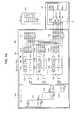
- FIG. 1A is a schematic circuit diagram illustrating a battery pack (100) and a charger (200) in a discharge standby mode according to an embodiment of the present invention
- FIG. 1B is a more detailed circuit diagram of FIG. 1A .
- the battery pack 100 includes a battery module 110, a battery management unit 120, and a control unit 130, such as a microcomputer.
- the battery module 110 includes a plurality of single battery units.
- the battery module 110 may include first to third single battery units 111, 112 and 113.
- the battery module 110 will be described in detail with regard to the battery module 110 including three single battery units, but it will be appreciated that the invention does not limit the battery module thereto.
- Each of the first to third single battery units 111, 112 and 113 includes a plurality of battery cells.
- the plurality of battery cells included in each of the first to third single battery units 111, 112 and 113 are connected to each other in series/parallel.
- first to third single battery units 111, 112 and 113 include electrode terminals, respectively.
- the first single battery unit 111 includes a first positive electrode terminal B1+ and a first negative electrode terminal B1-.
- the second single battery unit 112 includes a second positive electrode terminal B2+ and a second negative electrode terminal B2-.
- the third single battery unit 113 includes a third positive electrode terminal B3+ and a third negative electrode terminal B3-.
- the battery management unit 120 includes first to third single battery management units 121, 122 and 123, a charge terminal unit 124, and a discharge terminal unit 125.
- the first single battery management unit 121 includes a first charge/discharge switch 121 a, a first fuse unit 121b, a first control unit 121c, and a first charge/discharge terminal unit 121d.
- the first charge/discharge switch 121a may consist of a charge switch and a discharge switch.
- the charge switch and the discharge switch may be electrically connected between the first positive electrode terminal B1+ of the first single battery unit 111 and the first fuse unit 121 b.
- the first charge/discharge switch 121a allows the first single battery unit 111 to be charged/discharged and serves as a primary protective circuit device when over-charge or over-discharge occurs.
- the first fuse unit 121b may consist of a first fuse, a first heat resistor, and a first fuse switch.
- the first fuse unit 121b may serve as a secondary protective circuit device when the first charge/discharge switch 121a is damaged or malfunctions.
- the first fuse switch may be controlled by the first control unit 121c.
- the first control unit 121c controls a switching operation of the first charge/discharge switch 121a according to charge/discharge mode, thereby controlling charging/discharging of the first single battery unit 111.
- the first control unit 121c detects a voltage of the first single battery unit 111 and performs over-charge/over-discharge protection and voltage balancing of the first single battery unit 111 based on the detected voltage.
- the first charge/discharge terminal unit 121d includes a first positive electrode charge terminal CP1+ connected to the first fuse unit 121 b, a first positive electrode discharge terminal DP1+; as well as a first negative electrode charge terminal CP1- and a first negative electrode discharge terminal DP1- connected to the first negative electrode terminal B1- of the first single battery unit 111.
- the first positive electrode terminal B1+ of the first single battery unit 111 may be connected to the first positive electrode charge terminal CP1+ and the first positive electrode discharge terminal DP1+ through the first charge/discharge switch 121a and the first fuse unit 121b, respectively.
- first negative electrode terminal B1- of the first single battery unit 111 may be directly connected to the first negative electrode charge terminal CP1- and the first negative electrode discharge terminal DP1-.
- a current sensor 121e for sensing the current of the first single battery unit 111 may be provided between the first negative electrode terminal B1- and each of the first negative electrode charge terminal CP1- and the first negative electrode discharge terminal DP1-.
- the second single battery management unit 122 includes a second charge/discharge switch 122a, a fuse 122b, a second control unit 122c, and a second charge/discharge terminal unit 122d.
- the second charge/discharge switch 122a may consist of a charge switch and a discharge switch.
- the charge switch and the discharge switch may be electrically connected between the second positive electrode terminal B2+ of the second single battery unit 112 and the second fuse unit 122b.
- the second charge/discharge switch 122a allows the second single battery unit 112 to be charged/discharged and serves as a primary protective circuit device when over-charge or over-discharge occurs.
- the second fuse unit 122b may consist of a second fuse, a second heat resistor, and a second fuse switch.
- the second fuse unit 122b may serve as a secondary protective circuit device when the second charge/discharge switch 122a is damaged or malfunctions.
- the second fuse switch may be controlled by the second control unit 122c.
- the second control unit 122c controls a switching operation of the second charge/discharge switch 122a according to charge/discharge mode, thereby controlling charging/discharging of the second single battery unit 112.
- the second control unit 122c detects a voltage of the second single battery unit 112 and performs over-charge/over-discharge protection and voltage balancing of the second single battery unit 112 based on the detected voltage.
- the second charge/discharge terminal unit 122d includes a second positive electrode charge terminal CP2+ connected to the second fuse unit 121b, a second positive electrode discharge terminal DP2+, as well as a second negative electrode charge terminal CP2- and a second negative electrode discharge terminal DP2-connected to the second negative electrode terminal B2- of the second single battery unit 112.
- the second positive electrode terminal B2+ of the second single battery unit 112 may be connected to the second positive electrode charge terminal CP2+ and the second positive electrode discharge terminal DP2+ through the second charge/discharge switch 122a and the second fuse unit 122b, respectively.
- the second negative electrode terminal B2- of the second single battery unit 112 may be directly connected to the second negative electrode charge terminal CP2- and the second negative electrode discharge terminal DP2-.
- a current sensor 122e for sensing the current of the second single battery unit 111 may be provided between the second negative electrode terminal B1- and each of the second negative electrode charge terminal CP2- and the second negative electrode discharge terminal DP2-.
- the third single battery management unit 123 includes a third charge/discharge switch 123a, a fuse 123b, a third control unit 123c, and a third charge/discharge terminal unit 123d.
- the third charge/discharge switch 123a may consist of a charge switch and a discharge switch.
- the charge switch and the discharge switch may be electrically connected between the third positive electrode terminal B3+ of the third single battery unit 113 and the third fuse unit 122b.
- the third charge/discharge switch 123a allows the third single battery unit 113 to be charged/discharged and serves as a primary protective circuit device when over-charge or over-discharge occurs.
- the third fuse unit 123b may consist of a third fuse, a third heat resistor, and a third fuse switch.
- the third fuse unit 123b may serve as a secondary protective circuit device when the third charge/discharge switch 123a is damaged or malfunctions.
- the third fuse switch may be controlled by the third control unit 123c.
- the third control unit 123c controls a switching operation of the third charge/discharge switch 123a according to charge/discharge mode, thereby controlling charging/discharging of the third single battery unit 113.
- the third control unit 123c detects a voltage of the third single battery unit 113 and performs over-charge/over-discharge protection and voltage balancing of the third single battery unit 113 based on the detected voltage.
- the third charge/discharge terminal unit 123d includes a third positive electrode charge terminal CP3+ connected to the third fuse unit 123b, a third positive electrode discharge terminal DP3+, as well as a third negative electrode charge terminal CP3- and a third negative electrode discharge terminal DP3- connected to the third negative electrode terminal B3- of third single battery unit 113.
- the third positive electrode terminal B3+ of the third single battery unit 113 may be connected to the third positive electrode charge terminal CP3+ and the third positive electrode discharge terminal DP3+ through the third charge/discharge switch 123a and the third fuse unit 123b, respectively.
- the third negative electrode terminal B3- of the third single battery unit 113 may be directly connected to the third negative electrode charge terminal CP3- and the third negative electrode discharge terminal DP3-.
- a current sensor 123e for sensing the current of the third single battery unit 113 may be provided between the third negative electrode terminal B1- and each of the third negative electrode charge terminal CP3- and the third negative electrode discharge terminal DP3-.
- the charge terminal unit 124 includes first to third positive electrode charge terminals CP1+, CP2+ and CP3+ and first to third negative electrode charge terminals CP1-, CP2- and CP3-.
- the charge terminal unit 124 is used to gather charge terminals distributed in the first to third charge/discharge terminal units 121d, 122d, 123d into a single physical unit.
- the first positive electrode charge terminal CP1+, the second positive electrode charge terminal CP2+ and the third positive electrode charge terminal CP3+ of the charge terminal unit 124 are electrically connected in one-to-one correspondence to the first positive electrode charge terminal CP1+, the second positive electrode charge terminal CP2+ and the third positive electrode charge terminal CP3+ respectively included in the first to third charge/discharge terminal units 121d, 122d, 123d.
- first negative electrode charge terminal CP1-, the second negative electrode charge terminal CP2- and the third negative electrode charge terminal CP3- of the charge terminal unit 124 are electrically connected in one-to-one correspondence to the first negative electrode charge terminal CP1-, the second negative electrode charge terminal CP2- and the third negative electrode charge terminal CP3- respectively included in the first to third charge/discharge terminal unit 121d, 122d, 123d.
- the discharge terminal unit 125 includes first to third positive electrode discharge terminals DP1+, DP2+ and DP3+ and first to third negative electrode discharge terminals DP1-, DP2- and DP3-.
- the discharge terminal unit 125 is used to gather discharge terminals distributed in the first to third charge/discharge terminal unit 121d, 122d, 123d into a single physical unit.
- the first positive electrode discharge terminal DP1+, the second positive electrode discharge terminal DP2+ and the third positive electrode discharge terminal DP3+ of the discharge terminal unit 125 are electrically connected in one-to-one correspondence to the first positive electrode discharge terminal DP1+, the second positive electrode discharge terminal DP2+ and the third positive electrode discharge terminal DP3+ respectively included in the first to third charge/discharge terminal unit 121d, 122d, 123d.
- first negative electrode discharge terminal DP1-, the second negative electrode discharge terminal DP2- and the third negative electrode discharge terminal DP3- of the discharge terminal unit 125 are electrically connected in one-to-one correspondence to the first negative electrode discharge terminal DP1-, the second negative electrode discharge terminal DP2- and the third negative electrode discharge terminal DP3- respectively included in the first to third charge/discharge terminal unit 121d, 122d, 123d.
- the control unit 130 discriminates whether or not the charger 200 and an external power supply are connected to each other when the battery pack 100 and the charger 200 are connected to each other, and determines whether or not to cancel a series connection of the first to third single battery units 111, 112 and 113. An operation of the control unit 130 will later be described and configurations of the control unit 130 will further be described below.
- the control unit 130 includes charge recognizing units TB1 and TB2, discharge control terminal unit 131, and first and second discharge control switches SW1 and SW2.
- the charge recognizing units TB1 and TB2 of the control unit 130 are connected to charge recognizing units TB1 and TB2 of the charger 200.
- the charge recognizing units TB1 and TB2 of the control unit 130 consist of a positive electrode charge recognizing unit TB1 and a negative electrode charge recognizing unit TB2.
- the charge recognizing units TB1 and TB2 of the charger 200 consist of a positive electrode charge recognizing unit TB1 and a negative electrode charge recognizing unit TB2.
- the positive electrode charge recognizing unit TB1 of the control unit 130 is connected to the positive electrode charge recognizing unit TB1 of the charger 200
- the negative electrode charge recognizing unit TB2 of the control unit 130 is connected to the negative electrode charge recognizing unit TB2 of the charger 200.
- the control unit 130 detects a voltage of the charger 200 through the charge recognizing units TB1 and TB2 of the control unit 130 and controls switching operations of the first and second discharge control switches SW1 and SW2 according to whether a level of the detected voltage is shifted from 'high' to 'low' or vice versa, or whether a low level is maintained.
- the low level may be a first voltage level indicative that the battery pack is not connected to the charger 200 or that the charger 200 is disconnected from an external power supply for charging.
- the high level may be a second voltage level indicative that the battery pack is connected to the charger 200 and the charger 200 is connected to an external power supply for charging.
- the discharge control terminal unit 131 may consist of first and second positive electrode discharge control terminals and first and second negative electrode discharge control terminals.
- the first negative electrode discharge control terminal of the discharge control terminal unit 131 is electrically connected to the first negative discharge terminal DP1- of the discharge terminal unit 125
- the second negative electrode discharge control terminal of the discharge control terminal unit 131 is electrically connected to the second negative discharge terminal DP2- of the discharge terminal unit 125
- the first positive electrode discharge control terminal of the discharge control terminal unit 131 is electrically connected to the second positive discharge terminal DP2+ of the discharge terminal unit 125
- the second positive electrode discharge control terminal of the discharge control terminal unit 131 is electrically connected to the third positive discharge terminal DP3+ of the discharge terminal unit 125.
- the first positive electrode discharge terminal DP1+ of the discharge terminal unit 125 is electrically connected to a pack positive electrode terminal P1+
- the third negative electrode discharge terminal DP3- of the discharge terminal unit 125 is electrically connected to a pack negative electrode terminal P3-.
- the pack positive electrode terminal P1+ and the pack negative electrode terminal P3- are terminals which are connected to an external load when the battery pack 100 is discharged and through which current is output.
- the first discharge control switch SW1 is electrically connected between the first negative electrode discharge control terminal and the first positive electrode discharge control terminal of the discharge control unit 131.
- the second discharge control switch SW2 is electrically connected between the second negative electrode discharge control terminal and the second positive electrode discharge control terminal of the discharge control unit 131.
- diodes may be connected between the first negative electrode discharge control terminal and the first discharge control switch SW1 and between the second negative electrode discharge control terminal and the second discharge control switch SW2.
- the diodes allow the first to third single battery units to be connected in series so as to output a discharge current when a battery pack is discharged.
- the diodes D 1 and D2 allow series connections between each of the first to third single battery units to be cancelled in a secured manner.
- the control unit 130 turns on the first and second discharge control switches SW1 and SW2 to electrically connect a region between the first negative electrode discharge control terminal and the first positive electrode discharge control terminal and a region between the second negative electrode discharge control terminal and the second positive electrode discharge control terminal when the battery pack 100 is in a discharge standby mode, that is, in a natural discharge state.
- the first negative electrode terminal B1- of the first single battery unit 111 and the second positive electrode terminal B2+ of the second single battery unit 112 are connected to each other. If the regions between the second negative electrode discharge control terminal and the second positive electrode discharge control terminal are connected to each other, the second negative electrode terminal B2- of the second single battery unit 112 and the third positive electrode terminal B3+ of the third single battery unit 113 are connected, thereby establishing series connections between each of the first to third single battery units 111, 112 and 113.
- control unit 130 turns on the first and second discharge control switches SW1 and SW2 not only in a discharge standby mode but also in a discharge mode, thereby establishing series connections between each of the first to third single battery units 111, 112 and 113.
- the charger 200 includes a plurality of output terminals and the charge recognizing units TB1 and TB2.
- the output terminals of the charger 200 are configured to correspond to the first to third positive electrode charge terminal CP1+, CP2+, CP3+ and the first to third negative electrode charge terminal CP1-, CP2-, CP3-of the charge terminal unit 124 in one-to-one relationship.
- the plurality of output terminals consist of first to third positive electrode output terminals and first to third negative electrode output terminals.
- the charge recognizing units TB 1 and TB2 of the control unit 130 When the charge recognizing units TB 1 and TB2 of the control unit 130 are not connected to the charger 200, the charge recognizing units TB 1 and TB2 may be kept at low-level voltages. And, when the charge recognizing units TB1 and TB2 of the control unit 130 are connected to the charger 200, high-level voltages may be formed in the charge recognizing units TB1 and TB2 of the control unit 130, when for example the charger 200 is connected to an external power supply for charging..
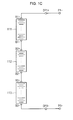
- FIG. 1C is an equivalent circuit diagram of a battery pack for the battery pack discharge standby mode of FIG. 1A
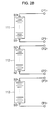
- FIG. 2A is a circuit diagram illustrating a battery pack and a charger in a charge standby mode according to an embodiment of the present invention
- FIG. 2B is an equivalent circuit diagram of a battery pack for the battery pack charge standby mode of FIG. 2A
- FIG. 3A is a circuit diagram illustrating a battery pack and a charger in a discharge mode according to an embodiment of the present invention
- FIG. 3B is an equivalent circuit diagram of a battery pack for the battery pack discharge mode of FIG. 3A
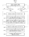
- FIG. 4 is a flowchart illustrating charge/discharge operation algorithm of a battery pack according to an embodiment of the present invention.
- control unit 130 In order to recognize a mode of the battery pack 100, the control unit 130 continuously detects voltages of the battery pack 100 through the charge recognizing units TB1 and TB2(S410).
- control unit 130 discriminates whether a level of the detected voltage is high (S420A) or low (S420B). As a discrimination result, when the level of the detected voltage is low (S420B), the control unit 130 recognizes that the battery pack 100 is in a discharge standby mode.
- control unit 130 turns on the first and second discharge control switches SW1 and SW2 to connect the first to third single battery units 111, 112 and 113 in series.
- control unit 130 turns on the first and second discharge control switches SW1 and SW2 to connected the first to third single battery units 111, 112 and 113 to each other in series when the battery pack 100 is not charged by the charger 200 or is not discharged by being connected to an external load, that is, is in a natural discharge state, which may be represented by an equivalent circuit shown in FIG. 1B .
- control unit 130 recognizes a mode of the battery pack 100 as a charge mode (S430). Accordingly, the control unit 130 turns off the first and second discharge control switches SW1 and SW2.
- the discharge terminals of the discharge terminal unit 125 are electrically disconnected from each other, thereby cancelling series connections between each of the first to third single battery units 111, 112 and 113.
- the output terminals of the charger 200 are connected to the charge terminal unit 124 of the battery pack 100.
- the respective charge terminals of the charge terminal unit 124 are connected to the electrode terminals of the first to third single battery units 111, 112 and 113, respectively, the first to third single battery units 111, 112 and 113 are connected in parallel with respect to the charger 200 (S440). Therefore, the first to third single battery units 111, 112 and 113 are charged in a state in which they are connected in parallel (S450).
- the control unit 130 maintains the first to third single battery units 111, 112 and 113 to be connected to each other in series.
- the discharge mode recognition and operation algorithms of the battery pack 100 are similar to the discharge standby mode recognition and operation algorithms. As a result of discrimination by the control unit 130, if the voltage level is low (S420B), the control unit 130 recognizes a discharge mode (S460).
- the control unit 130 turns on the first and second discharge control switches SW1 and SW2 to connect the first to third single battery units 111, 112 and 113 to each other in series (S470).
- the pack discharge terminals P1+ and P3- are connected to an external load, the first to third single battery units 111, 112 and 113 are discharged in a state in which they are connected in series through the pack discharge terminals P1+ and P3- (S480).
- the control unit 130 performs similar switch control operations depending on whether to recognize a discharge standby mode or a discharge mode is recognized. That is to say, since the control unit 130 turns on the first and second discharge control switches SW1 and SW2 in both the discharge standby mode and the discharge mode, the first to third single battery units 111, 112 and 113 are connected to each other in series in both cases.
- single battery units are charged by connecting the single battery units to each other in parallel during charging, thereby reducing a total charging time of the battery pack, and the single battery units are discharged by connecting the single battery units to each other in series during discharging, thereby achieving a higher output battery pack.
- a high-capacity battery pack can be charged using a low-capacity charger.
- a battery pack having a DC output voltage of 300 V can be charged using a charger having a DC output voltage of 100 V. That is to say, while the first to third single battery units are connected in series during discharging, providing for a DC output voltage of 300 V, the first to third single battery units are connected in parallel with respect to the charger during charging, thereby charging the first to third single battery units having a DC output of 100 V.
Landscapes
- Engineering & Computer Science (AREA)
- Manufacturing & Machinery (AREA)
- Chemical & Material Sciences (AREA)
- Chemical Kinetics & Catalysis (AREA)
- Electrochemistry (AREA)
- General Chemical & Material Sciences (AREA)
- Power Engineering (AREA)
- Charge And Discharge Circuits For Batteries Or The Like (AREA)
- Secondary Cells (AREA)
- Battery Mounting, Suspending (AREA)
Abstract
Description
- The present invention relates to a battery pack.
- Rechargeable secondary batteries are used as portable power sources for portable electronic equipment such as cellular phones, notebook computers, camcorders, personal digital assistants (PDA), and home appliances such as a vacuum cleaner. In a general home vacuum cleaner, a motor of the vacuum cleaner is driven using AC power in the home. However, in order to use the home vacuum cleaner in a space without AC power connected, a separate power source is necessary. The secondary battery used as a portable power source has different capacities according to the specification and high capacity power of approximately 100 V or higher is generally required to be used as the separate power source.
- Embodiments of the invention seek to provide a battery pack for achieving high-efficiency charging and high-power discharging.
- According to a first aspect of the invention there is provided a battery pack comprising: a battery module comprising a plurality of battery units, each battery unit being provided with respective electrode terminals; and a control unit for providing a first configuration in which the plurality of battery units are connected in series for discharging the battery module, and a second configuration in which the plurality of battery units are connected in parallel for charging the battery module.
- In an embodiment of the invention the battery pack includes a battery management device comprising a plurality of charge/discharge terminal units, each charge/discharge terminal unit comprising at least one charge terminal connected to an electrode terminal of a respective battery unit for charging the battery module; and at least one discharge terminal connected to an electrode terminal of the respective battery unit for discharging the battery module.
- In an embodiment of the invention the control unit comprises a plurality of discharge control terminals, each connected to a discharge terminal of a respective charge/discharge terminal unit of the battery management device; a charge recognition unit for detecting a level of an electrical charging parameter, and a discharge control switch arrangement connected to the discharge control terminals for switching, according to the level of the electrical charging parameter, between the first configuration and the second configuration.
- The electrical charging parameter may include any measurable electrical parameter related to the charging of a battery device such as a voltage level, a charge level or an intensity of current, for example.
- According to an embodiment of the invention in the first configuration at least two respective discharge control terminals are interconnected and in the second configuration the respective discharge control terminals are disconnected from one another.
- In an embodiment of the invention the charge recognition unit is operable to distinguish between a discharge mode and a charge mode, wherein the battery units are connected in series when the electrical charging parameter indicates a discharge mode of the battery module, and the battery units are connected in parallel when the electrical charging parameter indicates a charge mode of the battery module.
- A discharge mode may include a discharge mode or a discharge standby mode. A charge mode may include a charge mode and a charge standby mode.
- In an embodiment of the invention the electrical charging parameter comprises a charging voltage level from a charging device connected to the charge terminals of the battery management device and wherein when the charge recognition unit detects the charging voltage level shifting from high to low or remaining at a first level the control unit is operated to connect the battery units in series, and when the charge recognition unit detects the charging voltage level shifting from low to high or remaining at a second level, the control unit is operated to connect the battery units in parallel.
- For example the first level of voltage may correspond to a level of voltage when the battery pack is disconnected from a charging device and the second level of voltage may correspond to a level of voltage when the battery pack is connected to the charging device for charging of the battery pack.
- In an embodiment of the invention at least two of the discharge control terminals are connectable to an external load for discharging the battery module.
- In an embodiment of the invention the discharge control switch arrangement comprises one or more switches, the or each switch being arranged between respective discharge control terminals.
- In an embodiment of the invention each switch is arranged between respective discharge control terminals of opposing polarities.
- In an embodiment of the invention each charge/discharge terminal unit is arranged between the electrode terminals of the respective battery unit and a respective charge terminal unit, connectable to a charging device, or the respective discharge control terminal.
- In an embodiment of the invention each charge/discharge terminal unit comprises: a positive charge terminal, and a positive discharge terminal connected to the positive charge terminal; and a negative charge terminal, and a negative discharge terminal connected to the negative charge terminal.
- In an embodiment of the invention the positive charge terminal and the positive discharge terminal are connected to a positive electrode terminal of the electrode terminals and the negative charge terminal and the negative discharge terminal are connected to a negative electrode terminal of the electrode terminals.
- In an embodiment of the invention the positive charge terminal and the negative charge terminal are connected to the charge terminal unit.
- In an embodiment of the invention the positive discharge terminal and the negative discharge terminal are connected to the respective discharge control terminal.
- In an embodiment of the invention the discharge control switch arrangement further comprises one or more diodes arranged between respective discharge control terminals.
- In one embodiment of the invention there is provided a battery module including a plurality of single battery units, a battery management unit including a plurality of charge terminals and a plurality of discharge terminals electrically connected to electrode terminals of the plurality of single battery units, and controlling charging/discharging of the battery module, and a control unit including a plurality of discharge control terminals electrically connected to the plurality of discharge terminals, a discharge control switch installed between each of the plurality of discharge control terminals, and a charge recognizing unit, and controlling the operation of the discharge control switch according to the level of voltage detected by the charge recognizing unit.
-
-
FIG. 1A is a schematic circuit diagram illustrating a battery pack and a charger in a discharge standby mode according to an embodiment of the present invention; -
FIG. 1B is a more detailed circuit diagram ofFIG. 1A ; -
FIG. 1C is an equivalent circuit diagram of a battery pack for the battery pack discharge standby mode ofFIG. 1A ; -
FIG. 2A is a schematic circuit diagram illustrating a battery pack and a charger in a charge standby mode according to an embodiment of the present invention; -
FIG. 2B is an equivalent circuit diagram of a battery pack for the battery pack charge standby mode ofFIG. 2A ; -
FIG. 3A is a schematic circuit diagram illustrating a battery pack and a charger in a discharge mode according to an embodiment of the present invention; -
FIG. 3B is an equivalent circuit diagram of a battery pack for the battery pack discharge mode ofFIG. 3A ; and -
FIG. 4 is a flowchart illustrating steps of a charge/discharge operation algorithm of a battery pack according to an embodiment of the present invention. - Examplary embodiments will now be described more fully hereinafter with reference to the accompanying drawings; however, it will be appreciated that the invention may be embodied in different forms and should not be construed as limited to the embodiments set forth herein. Rather, these embodiments are provided so that this disclosure will be thorough and complete, and will fully convey the scope of the invention to those skilled in the art.
-
FIG. 1A is a schematic circuit diagram illustrating a battery pack (100) and a charger (200) in a discharge standby mode according to an embodiment of the present invention, andFIG. 1B is a more detailed circuit diagram ofFIG. 1A . - Referring to
FIGS. 1A and1B , thebattery pack 100 according to the embodiment of the present invention includes abattery module 110, abattery management unit 120, and acontrol unit 130, such as a microcomputer. - The
battery module 110 includes a plurality of single battery units. For example, as shown inFIG. 1A , thebattery module 110 may include first to thirdsingle battery units battery module 110 will be described in detail with regard to thebattery module 110 including three single battery units, but it will be appreciated that the invention does not limit the battery module thereto. - Each of the first to third
single battery units single battery units - In addition, the first to third
single battery units FIG. 1A , the firstsingle battery unit 111 includes a first positive electrode terminal B1+ and a first negative electrode terminal B1-. In addition, the secondsingle battery unit 112 includes a second positive electrode terminal B2+ and a second negative electrode terminal B2-. In addition, the thirdsingle battery unit 113 includes a third positive electrode terminal B3+ and a third negative electrode terminal B3-. - The
battery management unit 120 includes first to third singlebattery management units charge terminal unit 124, and adischarge terminal unit 125. - The first single
battery management unit 121 includes a first charge/discharge switch 121 a, afirst fuse unit 121b, afirst control unit 121c, and a first charge/discharge terminal unit 121d. - The first charge/
discharge switch 121a may consist of a charge switch and a discharge switch. The charge switch and the discharge switch may be electrically connected between the first positive electrode terminal B1+ of the firstsingle battery unit 111 and thefirst fuse unit 121 b. The first charge/discharge switch 121a allows the firstsingle battery unit 111 to be charged/discharged and serves as a primary protective circuit device when over-charge or over-discharge occurs. - The
first fuse unit 121b may consist of a first fuse, a first heat resistor, and a first fuse switch. In such a case, thefirst fuse unit 121b may serve as a secondary protective circuit device when the first charge/discharge switch 121a is damaged or malfunctions. Here, the first fuse switch may be controlled by thefirst control unit 121c. - The
first control unit 121c controls a switching operation of the first charge/discharge switch 121a according to charge/discharge mode, thereby controlling charging/discharging of the firstsingle battery unit 111. - In addition, the
first control unit 121c detects a voltage of the firstsingle battery unit 111 and performs over-charge/over-discharge protection and voltage balancing of the firstsingle battery unit 111 based on the detected voltage. - The first charge/
discharge terminal unit 121d includes a first positive electrode charge terminal CP1+ connected to thefirst fuse unit 121 b, a first positive electrode discharge terminal DP1+; as well as a first negative electrode charge terminal CP1- and a first negative electrode discharge terminal DP1- connected to the first negative electrode terminal B1- of the firstsingle battery unit 111. - For example, the first positive electrode terminal B1+ of the first
single battery unit 111 may be connected to the first positive electrode charge terminal CP1+ and the first positive electrode discharge terminal DP1+ through the first charge/discharge switch 121a and thefirst fuse unit 121b, respectively. - In addition, the first negative electrode terminal B1- of the first
single battery unit 111 may be directly connected to the first negative electrode charge terminal CP1- and the first negative electrode discharge terminal DP1-. Of course, acurrent sensor 121e for sensing the current of the firstsingle battery unit 111 may be provided between the first negative electrode terminal B1- and each of the first negative electrode charge terminal CP1- and the first negative electrode discharge terminal DP1-. - The second single
battery management unit 122 includes a second charge/discharge switch 122a, afuse 122b, asecond control unit 122c, and a second charge/discharge terminal unit 122d. - The second charge/
discharge switch 122a may consist of a charge switch and a discharge switch. The charge switch and the discharge switch may be electrically connected between the second positive electrode terminal B2+ of the secondsingle battery unit 112 and thesecond fuse unit 122b. The second charge/discharge switch 122a allows the secondsingle battery unit 112 to be charged/discharged and serves as a primary protective circuit device when over-charge or over-discharge occurs. - The
second fuse unit 122b may consist of a second fuse, a second heat resistor, and a second fuse switch. In such a case, thesecond fuse unit 122b may serve as a secondary protective circuit device when the second charge/discharge switch 122a is damaged or malfunctions. Here, the second fuse switch may be controlled by thesecond control unit 122c. - The
second control unit 122c controls a switching operation of the second charge/discharge switch 122a according to charge/discharge mode, thereby controlling charging/discharging of the secondsingle battery unit 112. - In addition, the
second control unit 122c detects a voltage of the secondsingle battery unit 112 and performs over-charge/over-discharge protection and voltage balancing of the secondsingle battery unit 112 based on the detected voltage. - The second charge/
discharge terminal unit 122d includes a second positive electrode charge terminal CP2+ connected to thesecond fuse unit 121b, a second positive electrode discharge terminal DP2+, as well as a second negative electrode charge terminal CP2- and a second negative electrode discharge terminal DP2-connected to the second negative electrode terminal B2- of the secondsingle battery unit 112. - The second positive electrode terminal B2+ of the second
single battery unit 112 may be connected to the second positive electrode charge terminal CP2+ and the second positive electrode discharge terminal DP2+ through the second charge/discharge switch 122a and thesecond fuse unit 122b, respectively. - In addition, the second negative electrode terminal B2- of the second
single battery unit 112 may be directly connected to the second negative electrode charge terminal CP2- and the second negative electrode discharge terminal DP2-. Of course, acurrent sensor 122e for sensing the current of the secondsingle battery unit 111 may be provided between the second negative electrode terminal B1- and each of the second negative electrode charge terminal CP2- and the second negative electrode discharge terminal DP2-. - The third single
battery management unit 123 includes a third charge/discharge switch 123a, afuse 123b, a third control unit 123c, and a third charge/discharge terminal unit 123d. - The third charge/
discharge switch 123a may consist of a charge switch and a discharge switch. The charge switch and the discharge switch may be electrically connected between the third positive electrode terminal B3+ of the thirdsingle battery unit 113 and thethird fuse unit 122b. The third charge/discharge switch 123a allows the thirdsingle battery unit 113 to be charged/discharged and serves as a primary protective circuit device when over-charge or over-discharge occurs. - The
third fuse unit 123b may consist of a third fuse, a third heat resistor, and a third fuse switch. In such a case, thethird fuse unit 123b may serve as a secondary protective circuit device when the third charge/discharge switch 123a is damaged or malfunctions. Here, the third fuse switch may be controlled by the third control unit 123c. - The third control unit 123c controls a switching operation of the third charge/
discharge switch 123a according to charge/discharge mode, thereby controlling charging/discharging of the thirdsingle battery unit 113. - In addition, the third control unit 123c detects a voltage of the third
single battery unit 113 and performs over-charge/over-discharge protection and voltage balancing of the thirdsingle battery unit 113 based on the detected voltage. - The third charge/
discharge terminal unit 123d includes a third positive electrode charge terminal CP3+ connected to thethird fuse unit 123b, a third positive electrode discharge terminal DP3+, as well as a third negative electrode charge terminal CP3- and a third negative electrode discharge terminal DP3- connected to the third negative electrode terminal B3- of thirdsingle battery unit 113. - The third positive electrode terminal B3+ of the third
single battery unit 113 may be connected to the third positive electrode charge terminal CP3+ and the third positive electrode discharge terminal DP3+ through the third charge/discharge switch 123a and thethird fuse unit 123b, respectively. - In addition, the third negative electrode terminal B3- of the third
single battery unit 113 may be directly connected to the third negative electrode charge terminal CP3- and the third negative electrode discharge terminal DP3-. Of course, acurrent sensor 123e for sensing the current of the thirdsingle battery unit 113 may be provided between the third negative electrode terminal B1- and each of the third negative electrode charge terminal CP3- and the third negative electrode discharge terminal DP3-. - The
charge terminal unit 124 includes first to third positive electrode charge terminals CP1+, CP2+ and CP3+ and first to third negative electrode charge terminals CP1-, CP2- and CP3-. Thecharge terminal unit 124 is used to gather charge terminals distributed in the first to third charge/discharge terminal units - Accordingly, the first positive electrode charge terminal CP1+, the second positive electrode charge terminal CP2+ and the third positive electrode charge terminal CP3+ of the
charge terminal unit 124 are electrically connected in one-to-one correspondence to the first positive electrode charge terminal CP1+, the second positive electrode charge terminal CP2+ and the third positive electrode charge terminal CP3+ respectively included in the first to third charge/discharge terminal units - In addition, the first negative electrode charge terminal CP1-, the second negative electrode charge terminal CP2- and the third negative electrode charge terminal CP3- of the
charge terminal unit 124 are electrically connected in one-to-one correspondence to the first negative electrode charge terminal CP1-, the second negative electrode charge terminal CP2- and the third negative electrode charge terminal CP3- respectively included in the first to third charge/discharge terminal unit - The
discharge terminal unit 125 includes first to third positive electrode discharge terminals DP1+, DP2+ and DP3+ and first to third negative electrode discharge terminals DP1-, DP2- and DP3-. Thedischarge terminal unit 125 is used to gather discharge terminals distributed in the first to third charge/discharge terminal unit - Accordingly, the first positive electrode discharge terminal DP1+, the second positive electrode discharge terminal DP2+ and the third positive electrode discharge terminal DP3+ of the
discharge terminal unit 125 are electrically connected in one-to-one correspondence to the first positive electrode discharge terminal DP1+, the second positive electrode discharge terminal DP2+ and the third positive electrode discharge terminal DP3+ respectively included in the first to third charge/discharge terminal unit - In addition, the first negative electrode discharge terminal DP1-, the second negative electrode discharge terminal DP2- and the third negative electrode discharge terminal DP3- of the
discharge terminal unit 125 are electrically connected in one-to-one correspondence to the first negative electrode discharge terminal DP1-, the second negative electrode discharge terminal DP2- and the third negative electrode discharge terminal DP3- respectively included in the first to third charge/discharge terminal unit - The
control unit 130 discriminates whether or not thecharger 200 and an external power supply are connected to each other when thebattery pack 100 and thecharger 200 are connected to each other, and determines whether or not to cancel a series connection of the first to thirdsingle battery units control unit 130 will later be described and configurations of thecontrol unit 130 will further be described below. - The
control unit 130 includes charge recognizing units TB1 and TB2, discharge controlterminal unit 131, and first and second discharge control switches SW1 and SW2. - When the
battery pack 100 is connected to thecharger 200, the charge recognizing units TB1 and TB2 of thecontrol unit 130 are connected to charge recognizing units TB1 and TB2 of thecharger 200. Here, the charge recognizing units TB1 and TB2 of thecontrol unit 130 consist of a positive electrode charge recognizing unit TB1 and a negative electrode charge recognizing unit TB2. Likewise, the charge recognizing units TB1 and TB2 of thecharger 200 consist of a positive electrode charge recognizing unit TB1 and a negative electrode charge recognizing unit TB2. Therefore, when thebattery pack 100 is connected to thecharger 200, the positive electrode charge recognizing unit TB1 of thecontrol unit 130 is connected to the positive electrode charge recognizing unit TB1 of thecharger 200, and the negative electrode charge recognizing unit TB2 of thecontrol unit 130 is connected to the negative electrode charge recognizing unit TB2 of thecharger 200. - The
control unit 130 detects a voltage of thecharger 200 through the charge recognizing units TB1 and TB2 of thecontrol unit 130 and controls switching operations of the first and second discharge control switches SW1 and SW2 according to whether a level of the detected voltage is shifted from 'high' to 'low' or vice versa, or whether a low level is maintained. For example, the low level may be a first voltage level indicative that the battery pack is not connected to thecharger 200 or that thecharger 200 is disconnected from an external power supply for charging. The high level may be a second voltage level indicative that the battery pack is connected to thecharger 200 and thecharger 200 is connected to an external power supply for charging. - The discharge
control terminal unit 131 may consist of first and second positive electrode discharge control terminals and first and second negative electrode discharge control terminals. - For example, the first negative electrode discharge control terminal of the discharge
control terminal unit 131 is electrically connected to the first negative discharge terminal DP1- of thedischarge terminal unit 125, and the second negative electrode discharge control terminal of the dischargecontrol terminal unit 131 is electrically connected to the second negative discharge terminal DP2- of thedischarge terminal unit 125. In addition, the first positive electrode discharge control terminal of the dischargecontrol terminal unit 131 is electrically connected to the second positive discharge terminal DP2+ of thedischarge terminal unit 125, and the second positive electrode discharge control terminal of the dischargecontrol terminal unit 131 is electrically connected to the third positive discharge terminal DP3+ of thedischarge terminal unit 125. - Meanwhile, the first positive electrode discharge terminal DP1+ of the
discharge terminal unit 125 is electrically connected to a pack positive electrode terminal P1+, and the third negative electrode discharge terminal DP3- of thedischarge terminal unit 125 is electrically connected to a pack negative electrode terminal P3-. The pack positive electrode terminal P1+ and the pack negative electrode terminal P3- are terminals which are connected to an external load when thebattery pack 100 is discharged and through which current is output. - The first discharge control switch SW1 is electrically connected between the first negative electrode discharge control terminal and the first positive electrode discharge control terminal of the
discharge control unit 131. In addition, the second discharge control switch SW2 is electrically connected between the second negative electrode discharge control terminal and the second positive electrode discharge control terminal of thedischarge control unit 131. Further, diodes may be connected between the first negative electrode discharge control terminal and the first discharge control switch SW1 and between the second negative electrode discharge control terminal and the second discharge control switch SW2. - The diodes allow the first to third single battery units to be connected in series so as to output a discharge current when a battery pack is discharged. When a battery pack is charged, the
diodes D 1 and D2 allow series connections between each of the first to third single battery units to be cancelled in a secured manner. As shown inFIG. 1A , thecontrol unit 130 turns on the first and second discharge control switches SW1 and SW2 to electrically connect a region between the first negative electrode discharge control terminal and the first positive electrode discharge control terminal and a region between the second negative electrode discharge control terminal and the second positive electrode discharge control terminal when thebattery pack 100 is in a discharge standby mode, that is, in a natural discharge state. Here, if the regions between the first negative electrode discharge control terminal and the first positive electrode discharge control terminal are connected to each other, the first negative electrode terminal B1- of the firstsingle battery unit 111 and the second positive electrode terminal B2+ of the secondsingle battery unit 112 are connected to each other. If the regions between the second negative electrode discharge control terminal and the second positive electrode discharge control terminal are connected to each other, the second negative electrode terminal B2- of the secondsingle battery unit 112 and the third positive electrode terminal B3+ of the thirdsingle battery unit 113 are connected, thereby establishing series connections between each of the first to thirdsingle battery units - Meanwhile, the
control unit 130 turns on the first and second discharge control switches SW1 and SW2 not only in a discharge standby mode but also in a discharge mode, thereby establishing series connections between each of the first to thirdsingle battery units - The
charger 200 includes a plurality of output terminals and the charge recognizing units TB1 and TB2. - The output terminals of the
charger 200 are configured to correspond to the first to third positive electrode charge terminal CP1+, CP2+, CP3+ and the first to third negative electrode charge terminal CP1-, CP2-, CP3-of thecharge terminal unit 124 in one-to-one relationship. For example, the plurality of output terminals consist of first to third positive electrode output terminals and first to third negative electrode output terminals. When thebattery pack 100 is connected to thecharger 200, the first to third positive electrode output terminals are connected to the positive electrode charge recognizing unit TB1 of thecharger 200, and the first to third negative electrode output terminals are connected to the negative electrode charge recognizing unit TB2 of thecharger 200. When the charge recognizingunits TB 1 and TB2 of thecontrol unit 130 are not connected to thecharger 200, the charge recognizingunits TB 1 and TB2 may be kept at low-level voltages. And, when the charge recognizing units TB1 and TB2 of thecontrol unit 130 are connected to thecharger 200, high-level voltages may be formed in the charge recognizing units TB1 and TB2 of thecontrol unit 130, when for example thecharger 200 is connected to an external power supply for charging.. - An operation of the
battery pack 100 according to an embodiment of the present invention will now be described in detail with reference to the accompanying drawings. -
FIG. 1C is an equivalent circuit diagram of a battery pack for the battery pack discharge standby mode ofFIG. 1A ,FIG. 2A is a circuit diagram illustrating a battery pack and a charger in a charge standby mode according to an embodiment of the present invention,FIG. 2B is an equivalent circuit diagram of a battery pack for the battery pack charge standby mode ofFIG. 2A ,FIG. 3A is a circuit diagram illustrating a battery pack and a charger in a discharge mode according to an embodiment of the present invention,FIG. 3B is an equivalent circuit diagram of a battery pack for the battery pack discharge mode ofFIG. 3A , andFIG. 4 is a flowchart illustrating charge/discharge operation algorithm of a battery pack according to an embodiment of the present invention. - In order to recognize a mode of the
battery pack 100, thecontrol unit 130 continuously detects voltages of thebattery pack 100 through the charge recognizing units TB1 and TB2(S410). - Thereafter, the
control unit 130 discriminates whether a level of the detected voltage is high (S420A) or low (S420B). As a discrimination result, when the level of the detected voltage is low (S420B), thecontrol unit 130 recognizes that thebattery pack 100 is in a discharge standby mode. - In this case, the
control unit 130 turns on the first and second discharge control switches SW1 and SW2 to connect the first to thirdsingle battery units control unit 130 turns on the first and second discharge control switches SW1 and SW2 to connected the first to thirdsingle battery units battery pack 100 is not charged by thecharger 200 or is not discharged by being connected to an external load, that is, is in a natural discharge state, which may be represented by an equivalent circuit shown inFIG. 1B . - When output terminals of the
charger 200 connected to an external power supply are physically, electrically connected to thecharge terminal unit 124 of thebattery pack 100, the level of the voltage detected through the charge recognizing units TB1 and TB2 of thecontrol unit 130 is shifted from 'low' to 'high' (S420A). - Here, the
control unit 130 recognizes a mode of thebattery pack 100 as a charge mode (S430). Accordingly, thecontrol unit 130 turns off the first and second discharge control switches SW1 and SW2. - In such a case, the discharge terminals of the
discharge terminal unit 125 are electrically disconnected from each other, thereby cancelling series connections between each of the first to thirdsingle battery units - At this time, the output terminals of the
charger 200 are connected to thecharge terminal unit 124 of thebattery pack 100. Here, since the respective charge terminals of thecharge terminal unit 124 are connected to the electrode terminals of the first to thirdsingle battery units single battery units single battery units - However, if the output terminals of the
charger 200 are connected to thecharge terminal unit 124 of thebattery pack 100 but thecharger 200 is not connected to an external power supply, the level of the voltage detected through the charge recognizing units TB1 and TB2 of thecontrol unit 130 is low. Therefore, thecontrol unit 130 maintains the first to thirdsingle battery units - The discharge mode recognition and operation algorithms of the
battery pack 100 are similar to the discharge standby mode recognition and operation algorithms. As a result of discrimination by thecontrol unit 130, if the voltage level is low (S420B), thecontrol unit 130 recognizes a discharge mode (S460). - In such a case, the
control unit 130 turns on the first and second discharge control switches SW1 and SW2 to connect the first to thirdsingle battery units single battery units - The
control unit 130 performs similar switch control operations depending on whether to recognize a discharge standby mode or a discharge mode is recognized. That is to say, since thecontrol unit 130 turns on the first and second discharge control switches SW1 and SW2 in both the discharge standby mode and the discharge mode, the first to thirdsingle battery units - Although automatic switching operation control of the
battery pack 100 according to the embodiment of the present invention has been described hereinabove, manual switching operation control may also be made without departing from the features of the present invention. - According to the present invention, single battery units are charged by connecting the single battery units to each other in parallel during charging, thereby reducing a total charging time of the battery pack, and the single battery units are discharged by connecting the single battery units to each other in series during discharging, thereby achieving a higher output battery pack.
- In addition, according to the present invention, a high-capacity battery pack can be charged using a low-capacity charger. For example, a battery pack having a DC output voltage of 300 V can be charged using a charger having a DC output voltage of 100 V. That is to say, while the first to third single battery units are connected in series during discharging, providing for a DC output voltage of 300 V, the first to third single battery units are connected in parallel with respect to the charger during charging, thereby charging the first to third single battery units having a DC output of 100 V.
- Exemplary embodiments have been disclosed herein, and although specific terms are employed, they are used and are to be interpreted in a generic and descriptive sense only and not for purpose of limitation. Accordingly, it will be understood by those of ordinary skill in the art that various changes in form and details may be made without departing from the spirit and scope of the present invention as set forth in the following claims.
Claims (15)
- A battery pack comprising:a battery module comprising a plurality of battery units, each battery unit being provided with respective electrode terminals; anda control unit for providing a first configuration in which the plurality of battery units are connected in series for discharging the battery module, and a second configuration in which the plurality of battery units are connected in parallel for charging the battery module.
- A battery pack according to claim 1 further comprising:a battery management device comprising:a plurality of charge/discharge terminal units, each charge/discharge terminal unit comprising at least one charge terminal connected to an electrode terminal of a respective battery unit for charging the battery module; and at least one discharge terminal connected to an electrode terminal of the respective battery unit for discharging the battery module.
- A battery pack according to claim 2 wherein the control unit comprises
a plurality of discharge control terminals, each connected to a discharge terminal of a respective charge/discharge terminal unit of the battery management device;
a charge recognition unit for detecting a level of an electrical charging parameter, and
a discharge control switch arrangement connected to the discharge control terminals for switching, according to the level of the electrical charging parameter, between the first configuration and the second configuration. - A battery pack according to claim 3 wherein in the first configuration at least two respective discharge control terminals are interconnected and in the second configuration the respective discharge control terminals are disconnected from one another.
- A battery pack according to claim 3 or 4 wherein the charge recognition unit is operable to distinguish between a discharge mode and a charge mode, wherein the battery units are connected in series when the electrical charging parameter indicates a discharge mode of the battery module, and the battery units are connected in parallel when the electrical charging parameter indicates a charge mode of the battery module.
- A battery pack according to claim 5 wherein the electrical charging parameter is the charging voltage level from a charging device connected to the charge terminals of the battery management device and wherein when the charge recognition unit detects the charging voltage level shifting from high to low or remaining at a first level the control unit is operated to connect the battery units in series, and when the charge recognition unit detects the charging voltage level shifting from low to high or remaining at a second level, the control unit is operated to connect the battery units in parallel.
- A battery pack according to any one of claims 2 to 6 wherein at least two of the discharge control terminals are connectable to an external load for discharging the battery module.
- A battery pack according to any one of claims 2 to 7 wherein the discharge control switch arrangement comprises one or more switches, the or each switch being arranged between respective discharge control terminals.
- A battery pack according to claim 8 wherein each switch is arranged between respective discharge control terminals of opposing polarities.
- A battery pack according to any one of claims 2 to 9 wherein each charge/discharge terminal unit is arranged between the electrode terminals of the respective battery unit and a respective charge terminal unit, connectable to a charging device, or the respective discharge control terminal.
- A battery pack according to any one of claims 2 to 10 wherein the each charge/discharge terminal unit comprises:a positive charge terminal, and a positive discharge terminal connected to the positive charge terminal; anda negative charge terminal, and a negative discharge terminal connected to the negative charge terminal.
- A battery pack according to claim 11 wherein the positive charge terminal and the positive discharge terminal are connected to a positive electrode terminal of the electrode terminals and the negative charge terminal and the negative discharge terminal are connected to a negative electrode terminal of the electrode terminals.
- A battery pack according to claim 11 or 12 wherein the positive charge terminal and the negative charge terminal are connected to the charge terminal unit.
- A battery pack according to any one of claims 11 to 13 wherein the positive discharge terminal and the negative discharge terminal are connected to the respective discharge control terminal.
- A battery pack according to any one of claims 8 to 14 wherein the discharge control switch arrangement further comprises one or more diodes arranged between respective discharge control terminals.
Applications Claiming Priority (2)
| Application Number | Priority Date | Filing Date | Title |
|---|---|---|---|
| US201161490542P | 2011-05-26 | 2011-05-26 | |
| US13/451,363 US9444118B2 (en) | 2011-05-26 | 2012-04-19 | Battery pack |
Publications (2)
| Publication Number | Publication Date |
|---|---|
| EP2528155A1 true EP2528155A1 (en) | 2012-11-28 |
| EP2528155B1 EP2528155B1 (en) | 2019-07-10 |
Family
ID=46148715
Family Applications (1)
| Application Number | Title | Priority Date | Filing Date |
|---|---|---|---|
| EP12169530.8A Active EP2528155B1 (en) | 2011-05-26 | 2012-05-25 | Battery pack |
Country Status (5)
| Country | Link |
|---|---|
| US (1) | US9444118B2 (en) |
| EP (1) | EP2528155B1 (en) |
| JP (1) | JP6293404B2 (en) |
| KR (1) | KR101419113B1 (en) |
| CN (2) | CN102800903A (en) |
Cited By (4)
| Publication number | Priority date | Publication date | Assignee | Title |
|---|---|---|---|---|
| CN104362374A (en) * | 2014-10-15 | 2015-02-18 | 东莞锂威能源科技有限公司 | Method for formation and capacity grading of small-capacity battery cells |
| EP3506451A4 (en) * | 2016-09-14 | 2019-08-14 | Huawei Technologies Co., Ltd. | FAST CHARGING METHOD FOR SERIAL BATTERY PACK AND DEVICE THEREOF |
| EP3556596A4 (en) * | 2016-12-13 | 2020-07-15 | Wonseok Jang | BATTERY CHARGING SYSTEM AND METHOD FOR AN ELECTRIC VEHICLE USING A MULTI-LAYER DIVIDING SCHEME |
| EP3764863A4 (en) * | 2018-03-13 | 2021-12-29 | LG Electronics Inc. | Cleaner |
Families Citing this family (24)
| Publication number | Priority date | Publication date | Assignee | Title |
|---|---|---|---|---|
| US9444118B2 (en) * | 2011-05-26 | 2016-09-13 | Samsung Sdi Co., Ltd. | Battery pack |
| JP6737709B2 (en) * | 2014-05-18 | 2020-08-12 | ブラック アンド デッカー インクBlack & Decker Inc. | Power tool system |
| CN107210698A (en) | 2014-06-19 | 2017-09-26 | 李平 | Motor, generator and direct current switch system, apparatus and method |
| US20150372279A1 (en) * | 2014-06-24 | 2015-12-24 | Turboroto Inc. | Active battery stack system and method |
| TWI614964B (en) * | 2014-08-01 | 2018-02-11 | 技嘉科技股份有限公司 | Fast low voltage rechargeable battery |
| KR101768316B1 (en) * | 2015-07-29 | 2017-08-14 | 엘지전자 주식회사 | Vacuum cleaner and battery assembly |
| TWI618523B (en) * | 2015-07-29 | 2018-03-21 | Lg電子股份有限公司 | Vacuum cleaner |
| US9692244B2 (en) * | 2015-09-08 | 2017-06-27 | Yung Ju Lee | Charging means and apparatus for secondary battery |
| CN105552461B (en) * | 2016-02-16 | 2018-02-06 | 深圳安博检测股份有限公司 | Portable vehicle rechargable battery electric discharge device |
| JP6883396B2 (en) * | 2016-08-25 | 2021-06-09 | 矢崎総業株式会社 | Quick charging device |
| GB2556914A (en) | 2016-11-25 | 2018-06-13 | Dyson Technology Ltd | Battery system |
| KR102204983B1 (en) * | 2017-09-25 | 2021-01-18 | 주식회사 엘지화학 | Apparatus for managing battery, battery pack including the same and vehicle including the same |
| KR102056876B1 (en) * | 2017-09-25 | 2019-12-17 | 주식회사 엘지화학 | Apparatus for managing battery, battery pack including the same and vehicle including the same |
| KR102202012B1 (en) * | 2017-10-18 | 2021-01-11 | 주식회사 엘지화학 | Battery back and power system including the same |
| DE102017222192A1 (en) * | 2017-12-07 | 2019-06-13 | Audi Ag | HV battery assembly for a motor vehicle, electrical system, motor vehicle and method for controlling a HV battery assembly |
| KR102390394B1 (en) * | 2018-05-15 | 2022-04-22 | 주식회사 엘지에너지솔루션 | Apparatus and method for controlling main battery and sub battery |
| CN109671971A (en) * | 2018-12-24 | 2019-04-23 | 深圳市中天和自动化设备有限公司 | A kind of device of full automatic packaging |
| US11117483B2 (en) * | 2019-10-02 | 2021-09-14 | Ford Global Technologies, Llc | Traction battery charging method and charging system |
| CN212726500U (en) | 2020-06-09 | 2021-03-16 | 中兴通讯股份有限公司 | Series-parallel battery system |
| GB202106907D0 (en) * | 2021-05-14 | 2021-06-30 | Intelligent Clean Energy Ltd | Battery charging and voltage supply system |
| US11777334B2 (en) * | 2021-11-11 | 2023-10-03 | Beta Air, Llc | System for charging multiple power sources and monitoring diode currents for faults |
| KR102617698B1 (en) * | 2023-03-29 | 2023-12-27 | 유호전기공업주식회사 | Gas Insulated Switchgear with embedded rechargeable DC power supply |
| KR20250085522A (en) | 2023-12-05 | 2025-06-12 | 주식회사 엘지에너지솔루션 | Easy-to-remove Battery Pack |
| US20260128423A1 (en) * | 2024-11-01 | 2026-05-07 | E-Zinc Inc. | Charge and discharge control system for a zinc-air battery |
Citations (3)
| Publication number | Priority date | Publication date | Assignee | Title |
|---|---|---|---|---|
| JPH08340641A (en) * | 1995-06-12 | 1996-12-24 | Tokyo R & D:Kk | Battery power circuit |
| US5811959A (en) * | 1996-12-27 | 1998-09-22 | Kejha; Joseph B. | Smart circuit board for multicell battery protection |
| US20100121511A1 (en) * | 2008-10-07 | 2010-05-13 | Boston-Power, Inc. | Li-ion battery array for vehicle and other large capacity applications |
Family Cites Families (20)
| Publication number | Priority date | Publication date | Assignee | Title |
|---|---|---|---|---|
| JPS58107032A (en) | 1981-12-18 | 1983-06-25 | 日本電気株式会社 | Charging circuit |
| JPH0684546A (en) | 1992-09-01 | 1994-03-25 | Japan Storage Battery Co Ltd | Storage battery device for electric automobile |
| JP4075260B2 (en) | 1999-12-27 | 2008-04-16 | ソニー株式会社 | Battery pack, power supply device, and charging and discharging method |
| KR100478832B1 (en) | 2002-06-18 | 2005-03-24 | 오우석 | A Management System for The Rechargerble Battery |
| JP4097582B2 (en) | 2003-09-12 | 2008-06-11 | 三洋電機株式会社 | Pack battery, electric device connectable to pack battery, and pack battery type determination method |
| US20060092583A1 (en) * | 2004-10-01 | 2006-05-04 | Alahmad Mahmoud A | Switch array and power management system for batteries and other energy storage elements |
| JP4874632B2 (en) * | 2005-11-15 | 2012-02-15 | プライムアースEvエナジー株式会社 | Battery pack |
| JP2008043009A (en) | 2006-08-03 | 2008-02-21 | Sony Corp | Battery pack and control method |
| JP4501080B2 (en) * | 2006-10-23 | 2010-07-14 | トヨタ自動車株式会社 | Battery pack and manufacturing method thereof |
| JP2008148387A (en) | 2006-12-06 | 2008-06-26 | Matsushita Electric Ind Co Ltd | Battery pack |
| KR100867803B1 (en) | 2006-12-11 | 2008-11-10 | 현대자동차주식회사 | Charge equalization circuit device of battery pack |
| KR101254687B1 (en) | 2006-12-20 | 2013-04-15 | 주식회사 엘지화학 | Protective circuit of secondary cell and method for controlling thereof |
| TWI337412B (en) | 2007-04-13 | 2011-02-11 | Cheng Uei Prec Ind Co Ltd | Charge and discharge system |
| KR20100032961A (en) | 2008-09-19 | 2010-03-29 | 주식회사 엘지화학 | System for charging battery of notebook computer by controlling fet |
| JP5289037B2 (en) | 2008-12-26 | 2013-09-11 | 三洋電機株式会社 | Secondary battery device |
| US8945735B2 (en) | 2009-02-23 | 2015-02-03 | Samsung Sdi Co., Ltd. | Built-in charge circuit for secondary battery and secondary battery with the built-in charge circuit |
| ATE557432T1 (en) * | 2009-11-19 | 2012-05-15 | Sb Limotive Co Ltd | BATTERY PACK |
| KR101211756B1 (en) | 2010-02-11 | 2012-12-12 | 삼성에스디아이 주식회사 | Battery Pack |
| CN201732841U (en) | 2010-05-04 | 2011-02-02 | 郑州德朗能电池有限公司 | Rechargeable power battery module |
| US9444118B2 (en) * | 2011-05-26 | 2016-09-13 | Samsung Sdi Co., Ltd. | Battery pack |
-
2012
- 2012-04-19 US US13/451,363 patent/US9444118B2/en active Active
- 2012-05-03 KR KR1020120046875A patent/KR101419113B1/en active Active
- 2012-05-25 EP EP12169530.8A patent/EP2528155B1/en active Active
- 2012-05-25 CN CN2012101668571A patent/CN102800903A/en active Pending
- 2012-05-25 JP JP2012119458A patent/JP6293404B2/en active Active
- 2012-05-25 CN CN201710946232.XA patent/CN107611469A/en active Pending
Patent Citations (3)
| Publication number | Priority date | Publication date | Assignee | Title |
|---|---|---|---|---|
| JPH08340641A (en) * | 1995-06-12 | 1996-12-24 | Tokyo R & D:Kk | Battery power circuit |
| US5811959A (en) * | 1996-12-27 | 1998-09-22 | Kejha; Joseph B. | Smart circuit board for multicell battery protection |
| US20100121511A1 (en) * | 2008-10-07 | 2010-05-13 | Boston-Power, Inc. | Li-ion battery array for vehicle and other large capacity applications |
Cited By (7)
| Publication number | Priority date | Publication date | Assignee | Title |
|---|---|---|---|---|
| CN104362374A (en) * | 2014-10-15 | 2015-02-18 | 东莞锂威能源科技有限公司 | Method for formation and capacity grading of small-capacity battery cells |
| EP3506451A4 (en) * | 2016-09-14 | 2019-08-14 | Huawei Technologies Co., Ltd. | FAST CHARGING METHOD FOR SERIAL BATTERY PACK AND DEVICE THEREOF |
| US10819124B2 (en) | 2016-09-14 | 2020-10-27 | Huawei Technologies Co., Ltd. | Fast charging method and related device for series battery pack |
| EP3556596A4 (en) * | 2016-12-13 | 2020-07-15 | Wonseok Jang | BATTERY CHARGING SYSTEM AND METHOD FOR AN ELECTRIC VEHICLE USING A MULTI-LAYER DIVIDING SCHEME |
| EP3764863A4 (en) * | 2018-03-13 | 2021-12-29 | LG Electronics Inc. | Cleaner |
| AU2019233998B2 (en) * | 2018-03-13 | 2022-02-17 | Lg Electronics Inc. | Cleaner |
| US11297991B2 (en) | 2018-03-13 | 2022-04-12 | Lg Electronics Inc. | Cleaner |
Also Published As
| Publication number | Publication date |
|---|---|
| US9444118B2 (en) | 2016-09-13 |
| CN107611469A (en) | 2018-01-19 |
| JP6293404B2 (en) | 2018-03-14 |
| KR101419113B1 (en) | 2014-07-11 |
| US20120299549A1 (en) | 2012-11-29 |
| EP2528155B1 (en) | 2019-07-10 |
| KR20120132336A (en) | 2012-12-05 |
| CN102800903A (en) | 2012-11-28 |
| JP2012249516A (en) | 2012-12-13 |
Similar Documents
| Publication | Publication Date | Title |
|---|---|---|
| EP2528155B1 (en) | Battery pack | |
| US9537331B2 (en) | Battery pack | |
| US10277064B2 (en) | Power tool and control method thereof | |
| US8994331B2 (en) | Method and apparatus for adapting a battery voltage | |
| EP2568526B1 (en) | Battery pack | |
| CN101350532B (en) | Over-voltage protected battery charger with bypass | |
| KR101975393B1 (en) | External battery | |
| CN103683373A (en) | Cell balancing circuit and cell balancing method using the same | |
| KR101811062B1 (en) | Balancing apparatus of secondary battery | |
| CN105048006A (en) | Battery system and method for operting battery system | |
| CN103329338A (en) | Battery packs and power consumers | |
| US10367358B2 (en) | Active equalizing charging device | |
| CN103001288B (en) | Battery set charge/discharge equalization methods, balancer and attending device | |
| CN101325342A (en) | Charger for storage battery | |
| WO2015017896A1 (en) | Battery balancing system and method | |
| KR20150107032A (en) | Battery pack | |
| JP4108339B2 (en) | Lithium ion secondary battery charging method and apparatus | |
| JP5187040B2 (en) | Rechargeable battery charger | |
| KR101639885B1 (en) | Constant voltage source battery assist device and battery pack comrising the same | |
| KR102161289B1 (en) | External battery | |
| KR20150107031A (en) | External battery | |
| EP4568056A1 (en) | Battery pack group and driving method thereof | |
| KR20150017881A (en) | External battery and driving method thereof | |
| KR101973049B1 (en) | External battery | |
| JPH0765868A (en) | Battery device |
Legal Events
| Date | Code | Title | Description |
|---|---|---|---|
| PUAI | Public reference made under article 153(3) epc to a published international application that has entered the european phase |
Free format text: ORIGINAL CODE: 0009012 |
|
| AK | Designated contracting states |
Kind code of ref document: A1 Designated state(s): AL AT BE BG CH CY CZ DE DK EE ES FI FR GB GR HR HU IE IS IT LI LT LU LV MC MK MT NL NO PL PT RO RS SE SI SK SM TR |
|
| AX | Request for extension of the european patent |
Extension state: BA ME |
|
| 17P | Request for examination filed |
Effective date: 20130430 |
|
| 17Q | First examination report despatched |
Effective date: 20150127 |
|
| STAA | Information on the status of an ep patent application or granted ep patent |
Free format text: STATUS: EXAMINATION IS IN PROGRESS |
|
| RIC1 | Information provided on ipc code assigned before grant |
Ipc: H01M 10/42 20060101ALN20181109BHEP Ipc: H01M 10/44 20060101AFI20181109BHEP Ipc: H01M 10/48 20060101ALN20181109BHEP Ipc: H01M 10/04 20060101ALI20181109BHEP Ipc: H02J 7/00 20060101ALI20181109BHEP |
|
| GRAP | Despatch of communication of intention to grant a patent |
Free format text: ORIGINAL CODE: EPIDOSNIGR1 |
|
| STAA | Information on the status of an ep patent application or granted ep patent |
Free format text: STATUS: GRANT OF PATENT IS INTENDED |
|
| INTG | Intention to grant announced |
Effective date: 20190102 |
|
| GRAS | Grant fee paid |
Free format text: ORIGINAL CODE: EPIDOSNIGR3 |
|
| GRAA | (expected) grant |
Free format text: ORIGINAL CODE: 0009210 |
|
| STAA | Information on the status of an ep patent application or granted ep patent |
Free format text: STATUS: THE PATENT HAS BEEN GRANTED |
|
| AK | Designated contracting states |
Kind code of ref document: B1 Designated state(s): AL AT BE BG CH CY CZ DE DK EE ES FI FR GB GR HR HU IE IS IT LI LT LU LV MC MK MT NL NO PL PT RO RS SE SI SK SM TR |
|
| REG | Reference to a national code |
Ref country code: GB Ref legal event code: FG4D |
|
| REG | Reference to a national code |
Ref country code: CH Ref legal event code: EP Ref country code: AT Ref legal event code: REF Ref document number: 1154484 Country of ref document: AT Kind code of ref document: T Effective date: 20190715 |
|
| REG | Reference to a national code |
Ref country code: DE Ref legal event code: R096 Ref document number: 602012061838 Country of ref document: DE |
|
| REG | Reference to a national code |
Ref country code: IE Ref legal event code: FG4D |
|
| REG | Reference to a national code |
Ref country code: NL Ref legal event code: MP Effective date: 20190710 |
|
| REG | Reference to a national code |
Ref country code: LT Ref legal event code: MG4D |
|
| REG | Reference to a national code |
Ref country code: AT Ref legal event code: MK05 Ref document number: 1154484 Country of ref document: AT Kind code of ref document: T Effective date: 20190710 |
|
| PG25 | Lapsed in a contracting state [announced via postgrant information from national office to epo] |
Ref country code: HR Free format text: LAPSE BECAUSE OF FAILURE TO SUBMIT A TRANSLATION OF THE DESCRIPTION OR TO PAY THE FEE WITHIN THE PRESCRIBED TIME-LIMIT Effective date: 20190710 Ref country code: NL Free format text: LAPSE BECAUSE OF FAILURE TO SUBMIT A TRANSLATION OF THE DESCRIPTION OR TO PAY THE FEE WITHIN THE PRESCRIBED TIME-LIMIT Effective date: 20190710 Ref country code: BG Free format text: LAPSE BECAUSE OF FAILURE TO SUBMIT A TRANSLATION OF THE DESCRIPTION OR TO PAY THE FEE WITHIN THE PRESCRIBED TIME-LIMIT Effective date: 20191010 Ref country code: PT Free format text: LAPSE BECAUSE OF FAILURE TO SUBMIT A TRANSLATION OF THE DESCRIPTION OR TO PAY THE FEE WITHIN THE PRESCRIBED TIME-LIMIT Effective date: 20191111 Ref country code: LT Free format text: LAPSE BECAUSE OF FAILURE TO SUBMIT A TRANSLATION OF THE DESCRIPTION OR TO PAY THE FEE WITHIN THE PRESCRIBED TIME-LIMIT Effective date: 20190710 Ref country code: SE Free format text: LAPSE BECAUSE OF FAILURE TO SUBMIT A TRANSLATION OF THE DESCRIPTION OR TO PAY THE FEE WITHIN THE PRESCRIBED TIME-LIMIT Effective date: 20190710 Ref country code: AT Free format text: LAPSE BECAUSE OF FAILURE TO SUBMIT A TRANSLATION OF THE DESCRIPTION OR TO PAY THE FEE WITHIN THE PRESCRIBED TIME-LIMIT Effective date: 20190710 Ref country code: NO Free format text: LAPSE BECAUSE OF FAILURE TO SUBMIT A TRANSLATION OF THE DESCRIPTION OR TO PAY THE FEE WITHIN THE PRESCRIBED TIME-LIMIT Effective date: 20191010 Ref country code: FI Free format text: LAPSE BECAUSE OF FAILURE TO SUBMIT A TRANSLATION OF THE DESCRIPTION OR TO PAY THE FEE WITHIN THE PRESCRIBED TIME-LIMIT Effective date: 20190710 |
|
| PG25 | Lapsed in a contracting state [announced via postgrant information from national office to epo] |
Ref country code: RS Free format text: LAPSE BECAUSE OF FAILURE TO SUBMIT A TRANSLATION OF THE DESCRIPTION OR TO PAY THE FEE WITHIN THE PRESCRIBED TIME-LIMIT Effective date: 20190710 Ref country code: IS Free format text: LAPSE BECAUSE OF FAILURE TO SUBMIT A TRANSLATION OF THE DESCRIPTION OR TO PAY THE FEE WITHIN THE PRESCRIBED TIME-LIMIT Effective date: 20191110 Ref country code: AL Free format text: LAPSE BECAUSE OF FAILURE TO SUBMIT A TRANSLATION OF THE DESCRIPTION OR TO PAY THE FEE WITHIN THE PRESCRIBED TIME-LIMIT Effective date: 20190710 Ref country code: ES Free format text: LAPSE BECAUSE OF FAILURE TO SUBMIT A TRANSLATION OF THE DESCRIPTION OR TO PAY THE FEE WITHIN THE PRESCRIBED TIME-LIMIT Effective date: 20190710 Ref country code: GR Free format text: LAPSE BECAUSE OF FAILURE TO SUBMIT A TRANSLATION OF THE DESCRIPTION OR TO PAY THE FEE WITHIN THE PRESCRIBED TIME-LIMIT Effective date: 20191011 Ref country code: LV Free format text: LAPSE BECAUSE OF FAILURE TO SUBMIT A TRANSLATION OF THE DESCRIPTION OR TO PAY THE FEE WITHIN THE PRESCRIBED TIME-LIMIT Effective date: 20190710 |
|
| PG25 | Lapsed in a contracting state [announced via postgrant information from national office to epo] |
Ref country code: TR Free format text: LAPSE BECAUSE OF FAILURE TO SUBMIT A TRANSLATION OF THE DESCRIPTION OR TO PAY THE FEE WITHIN THE PRESCRIBED TIME-LIMIT Effective date: 20190710 |
|
| PG25 | Lapsed in a contracting state [announced via postgrant information from national office to epo] |
Ref country code: PL Free format text: LAPSE BECAUSE OF FAILURE TO SUBMIT A TRANSLATION OF THE DESCRIPTION OR TO PAY THE FEE WITHIN THE PRESCRIBED TIME-LIMIT Effective date: 20190710 Ref country code: DK Free format text: LAPSE BECAUSE OF FAILURE TO SUBMIT A TRANSLATION OF THE DESCRIPTION OR TO PAY THE FEE WITHIN THE PRESCRIBED TIME-LIMIT Effective date: 20190710 Ref country code: IT Free format text: LAPSE BECAUSE OF FAILURE TO SUBMIT A TRANSLATION OF THE DESCRIPTION OR TO PAY THE FEE WITHIN THE PRESCRIBED TIME-LIMIT Effective date: 20190710 Ref country code: EE Free format text: LAPSE BECAUSE OF FAILURE TO SUBMIT A TRANSLATION OF THE DESCRIPTION OR TO PAY THE FEE WITHIN THE PRESCRIBED TIME-LIMIT Effective date: 20190710 Ref country code: RO Free format text: LAPSE BECAUSE OF FAILURE TO SUBMIT A TRANSLATION OF THE DESCRIPTION OR TO PAY THE FEE WITHIN THE PRESCRIBED TIME-LIMIT Effective date: 20190710 |
|
| PG25 | Lapsed in a contracting state [announced via postgrant information from national office to epo] |
Ref country code: SM Free format text: LAPSE BECAUSE OF FAILURE TO SUBMIT A TRANSLATION OF THE DESCRIPTION OR TO PAY THE FEE WITHIN THE PRESCRIBED TIME-LIMIT Effective date: 20190710 Ref country code: IS Free format text: LAPSE BECAUSE OF FAILURE TO SUBMIT A TRANSLATION OF THE DESCRIPTION OR TO PAY THE FEE WITHIN THE PRESCRIBED TIME-LIMIT Effective date: 20200224 Ref country code: SK Free format text: LAPSE BECAUSE OF FAILURE TO SUBMIT A TRANSLATION OF THE DESCRIPTION OR TO PAY THE FEE WITHIN THE PRESCRIBED TIME-LIMIT Effective date: 20190710 Ref country code: CZ Free format text: LAPSE BECAUSE OF FAILURE TO SUBMIT A TRANSLATION OF THE DESCRIPTION OR TO PAY THE FEE WITHIN THE PRESCRIBED TIME-LIMIT Effective date: 20190710 |
|
| REG | Reference to a national code |
Ref country code: DE Ref legal event code: R097 Ref document number: 602012061838 Country of ref document: DE |
|
| PLBE | No opposition filed within time limit |
Free format text: ORIGINAL CODE: 0009261 |
|
| STAA | Information on the status of an ep patent application or granted ep patent |
Free format text: STATUS: NO OPPOSITION FILED WITHIN TIME LIMIT |
|
| PG2D | Information on lapse in contracting state deleted |
Ref country code: IS |
|
| 26N | No opposition filed |
Effective date: 20200603 |
|
| PG25 | Lapsed in a contracting state [announced via postgrant information from national office to epo] |
Ref country code: SI Free format text: LAPSE BECAUSE OF FAILURE TO SUBMIT A TRANSLATION OF THE DESCRIPTION OR TO PAY THE FEE WITHIN THE PRESCRIBED TIME-LIMIT Effective date: 20190710 |
|
| PG25 | Lapsed in a contracting state [announced via postgrant information from national office to epo] |
Ref country code: LI Free format text: LAPSE BECAUSE OF NON-PAYMENT OF DUE FEES Effective date: 20200531 Ref country code: CH Free format text: LAPSE BECAUSE OF NON-PAYMENT OF DUE FEES Effective date: 20200531 Ref country code: MC Free format text: LAPSE BECAUSE OF FAILURE TO SUBMIT A TRANSLATION OF THE DESCRIPTION OR TO PAY THE FEE WITHIN THE PRESCRIBED TIME-LIMIT Effective date: 20190710 |
|
| REG | Reference to a national code |
Ref country code: BE Ref legal event code: MM Effective date: 20200531 |
|
| PG25 | Lapsed in a contracting state [announced via postgrant information from national office to epo] |
Ref country code: LU Free format text: LAPSE BECAUSE OF NON-PAYMENT OF DUE FEES Effective date: 20200525 |
|
| PG25 | Lapsed in a contracting state [announced via postgrant information from national office to epo] |
Ref country code: IE Free format text: LAPSE BECAUSE OF NON-PAYMENT OF DUE FEES Effective date: 20200525 |
|
| PG25 | Lapsed in a contracting state [announced via postgrant information from national office to epo] |
Ref country code: BE Free format text: LAPSE BECAUSE OF NON-PAYMENT OF DUE FEES Effective date: 20200531 |
|
| PG25 | Lapsed in a contracting state [announced via postgrant information from national office to epo] |
Ref country code: MT Free format text: LAPSE BECAUSE OF FAILURE TO SUBMIT A TRANSLATION OF THE DESCRIPTION OR TO PAY THE FEE WITHIN THE PRESCRIBED TIME-LIMIT Effective date: 20190710 Ref country code: CY Free format text: LAPSE BECAUSE OF FAILURE TO SUBMIT A TRANSLATION OF THE DESCRIPTION OR TO PAY THE FEE WITHIN THE PRESCRIBED TIME-LIMIT Effective date: 20190710 |
|
| PG25 | Lapsed in a contracting state [announced via postgrant information from national office to epo] |
Ref country code: MK Free format text: LAPSE BECAUSE OF FAILURE TO SUBMIT A TRANSLATION OF THE DESCRIPTION OR TO PAY THE FEE WITHIN THE PRESCRIBED TIME-LIMIT Effective date: 20190710 |
|
| P01 | Opt-out of the competence of the unified patent court (upc) registered |
Effective date: 20230528 |
|
| PGFP | Annual fee paid to national office [announced via postgrant information from national office to epo] |
Ref country code: DE Payment date: 20250429 Year of fee payment: 14 |
|
| PGFP | Annual fee paid to national office [announced via postgrant information from national office to epo] |
Ref country code: GB Payment date: 20250501 Year of fee payment: 14 |
|
| PGFP | Annual fee paid to national office [announced via postgrant information from national office to epo] |
Ref country code: FR Payment date: 20250508 Year of fee payment: 14 |