EP2528143A1 - Power storage element provided with a current collector, and method of manufacturing current collector - Google Patents
Power storage element provided with a current collector, and method of manufacturing current collector Download PDFInfo
- Publication number
- EP2528143A1 EP2528143A1 EP11818035A EP11818035A EP2528143A1 EP 2528143 A1 EP2528143 A1 EP 2528143A1 EP 11818035 A EP11818035 A EP 11818035A EP 11818035 A EP11818035 A EP 11818035A EP 2528143 A1 EP2528143 A1 EP 2528143A1
- Authority
- EP
- European Patent Office
- Prior art keywords
- twisted
- current collecting
- end portion
- collecting member
- positive
- Prior art date
- Legal status (The legal status is an assumption and is not a legal conclusion. Google has not performed a legal analysis and makes no representation as to the accuracy of the status listed.)
- Granted
Links
- 238000003860 storage Methods 0.000 title claims abstract description 33
- 238000004519 manufacturing process Methods 0.000 title claims abstract description 6
- 238000003780 insertion Methods 0.000 claims abstract description 102
- 230000037431 insertion Effects 0.000 claims abstract description 102
- 238000000034 method Methods 0.000 claims abstract description 11
- 239000002184 metal Substances 0.000 claims description 40
- 238000012545 processing Methods 0.000 claims description 6
- 238000013459 approach Methods 0.000 claims description 4
- 239000003990 capacitor Substances 0.000 description 8
- 239000011888 foil Substances 0.000 description 7
- 238000003466 welding Methods 0.000 description 7
- 230000035882 stress Effects 0.000 description 5
- 238000005452 bending Methods 0.000 description 3
- 230000008878 coupling Effects 0.000 description 3
- 238000010168 coupling process Methods 0.000 description 3
- 238000005859 coupling reaction Methods 0.000 description 3
- 239000007773 negative electrode material Substances 0.000 description 3
- 239000007774 positive electrode material Substances 0.000 description 3
- 238000004804 winding Methods 0.000 description 3
- 239000011248 coating agent Substances 0.000 description 2
- 238000000576 coating method Methods 0.000 description 2
- 230000000694 effects Effects 0.000 description 2
- 230000006355 external stress Effects 0.000 description 2
- HBBGRARXTFLTSG-UHFFFAOYSA-N Lithium ion Chemical compound [Li+] HBBGRARXTFLTSG-UHFFFAOYSA-N 0.000 description 1
- 239000012141 concentrate Substances 0.000 description 1
- 230000008602 contraction Effects 0.000 description 1
- 238000007714 electro crystallization reaction Methods 0.000 description 1
- 239000008151 electrolyte solution Substances 0.000 description 1
- 229910001416 lithium ion Inorganic materials 0.000 description 1
- 229910052987 metal hydride Inorganic materials 0.000 description 1
- 239000007769 metal material Substances 0.000 description 1
- 230000000149 penetrating effect Effects 0.000 description 1
- 238000007790 scraping Methods 0.000 description 1
- 238000007789 sealing Methods 0.000 description 1
- 210000002105 tongue Anatomy 0.000 description 1
- 238000012546 transfer Methods 0.000 description 1
Images


Classifications
-
- H—ELECTRICITY
- H01—ELECTRIC ELEMENTS
- H01M—PROCESSES OR MEANS, e.g. BATTERIES, FOR THE DIRECT CONVERSION OF CHEMICAL ENERGY INTO ELECTRICAL ENERGY
- H01M50/00—Constructional details or processes of manufacture of the non-active parts of electrochemical cells other than fuel cells, e.g. hybrid cells
- H01M50/50—Current conducting connections for cells or batteries
- H01M50/531—Electrode connections inside a battery casing
-
- H—ELECTRICITY
- H01—ELECTRIC ELEMENTS
- H01G—CAPACITORS; CAPACITORS, RECTIFIERS, DETECTORS, SWITCHING DEVICES OR LIGHT-SENSITIVE DEVICES, OF THE ELECTROLYTIC TYPE
- H01G11/00—Hybrid capacitors, i.e. capacitors having different positive and negative electrodes; Electric double-layer [EDL] capacitors; Processes for the manufacture thereof or of parts thereof
- H01G11/66—Current collectors
-
- H—ELECTRICITY
- H01—ELECTRIC ELEMENTS
- H01G—CAPACITORS; CAPACITORS, RECTIFIERS, DETECTORS, SWITCHING DEVICES OR LIGHT-SENSITIVE DEVICES, OF THE ELECTROLYTIC TYPE
- H01G11/00—Hybrid capacitors, i.e. capacitors having different positive and negative electrodes; Electric double-layer [EDL] capacitors; Processes for the manufacture thereof or of parts thereof
- H01G11/04—Hybrid capacitors
- H01G11/06—Hybrid capacitors with one of the electrodes allowing ions to be reversibly doped thereinto, e.g. lithium ion capacitors [LIC]
-
- H—ELECTRICITY
- H01—ELECTRIC ELEMENTS
- H01G—CAPACITORS; CAPACITORS, RECTIFIERS, DETECTORS, SWITCHING DEVICES OR LIGHT-SENSITIVE DEVICES, OF THE ELECTROLYTIC TYPE
- H01G11/00—Hybrid capacitors, i.e. capacitors having different positive and negative electrodes; Electric double-layer [EDL] capacitors; Processes for the manufacture thereof or of parts thereof
- H01G11/22—Electrodes
- H01G11/24—Electrodes characterised by structural features of the materials making up or comprised in the electrodes, e.g. form, surface area or porosity; characterised by the structural features of powders or particles used therefor
-
- H—ELECTRICITY
- H01—ELECTRIC ELEMENTS
- H01G—CAPACITORS; CAPACITORS, RECTIFIERS, DETECTORS, SWITCHING DEVICES OR LIGHT-SENSITIVE DEVICES, OF THE ELECTROLYTIC TYPE
- H01G11/00—Hybrid capacitors, i.e. capacitors having different positive and negative electrodes; Electric double-layer [EDL] capacitors; Processes for the manufacture thereof or of parts thereof
- H01G11/66—Current collectors
- H01G11/70—Current collectors characterised by their structure
-
- H—ELECTRICITY
- H01—ELECTRIC ELEMENTS
- H01G—CAPACITORS; CAPACITORS, RECTIFIERS, DETECTORS, SWITCHING DEVICES OR LIGHT-SENSITIVE DEVICES, OF THE ELECTROLYTIC TYPE
- H01G11/00—Hybrid capacitors, i.e. capacitors having different positive and negative electrodes; Electric double-layer [EDL] capacitors; Processes for the manufacture thereof or of parts thereof
- H01G11/74—Terminals, e.g. extensions of current collectors
-
- H—ELECTRICITY
- H01—ELECTRIC ELEMENTS
- H01G—CAPACITORS; CAPACITORS, RECTIFIERS, DETECTORS, SWITCHING DEVICES OR LIGHT-SENSITIVE DEVICES, OF THE ELECTROLYTIC TYPE
- H01G11/00—Hybrid capacitors, i.e. capacitors having different positive and negative electrodes; Electric double-layer [EDL] capacitors; Processes for the manufacture thereof or of parts thereof
- H01G11/84—Processes for the manufacture of hybrid or EDL capacitors, or components thereof
-
- H—ELECTRICITY
- H01—ELECTRIC ELEMENTS
- H01M—PROCESSES OR MEANS, e.g. BATTERIES, FOR THE DIRECT CONVERSION OF CHEMICAL ENERGY INTO ELECTRICAL ENERGY
- H01M10/00—Secondary cells; Manufacture thereof
- H01M10/04—Construction or manufacture in general
- H01M10/0431—Cells with wound or folded electrodes
-
- H—ELECTRICITY
- H01—ELECTRIC ELEMENTS
- H01M—PROCESSES OR MEANS, e.g. BATTERIES, FOR THE DIRECT CONVERSION OF CHEMICAL ENERGY INTO ELECTRICAL ENERGY
- H01M10/00—Secondary cells; Manufacture thereof
- H01M10/05—Accumulators with non-aqueous electrolyte
- H01M10/052—Li-accumulators
- H01M10/0525—Rocking-chair batteries, i.e. batteries with lithium insertion or intercalation in both electrodes; Lithium-ion batteries
-
- H—ELECTRICITY
- H01—ELECTRIC ELEMENTS
- H01M—PROCESSES OR MEANS, e.g. BATTERIES, FOR THE DIRECT CONVERSION OF CHEMICAL ENERGY INTO ELECTRICAL ENERGY
- H01M10/00—Secondary cells; Manufacture thereof
- H01M10/05—Accumulators with non-aqueous electrolyte
- H01M10/058—Construction or manufacture
-
- H—ELECTRICITY
- H01—ELECTRIC ELEMENTS
- H01M—PROCESSES OR MEANS, e.g. BATTERIES, FOR THE DIRECT CONVERSION OF CHEMICAL ENERGY INTO ELECTRICAL ENERGY
- H01M50/00—Constructional details or processes of manufacture of the non-active parts of electrochemical cells other than fuel cells, e.g. hybrid cells
- H01M50/50—Current conducting connections for cells or batteries
- H01M50/531—Electrode connections inside a battery casing
- H01M50/533—Electrode connections inside a battery casing characterised by the shape of the leads or tabs
-
- H—ELECTRICITY
- H01—ELECTRIC ELEMENTS
- H01M—PROCESSES OR MEANS, e.g. BATTERIES, FOR THE DIRECT CONVERSION OF CHEMICAL ENERGY INTO ELECTRICAL ENERGY
- H01M50/00—Constructional details or processes of manufacture of the non-active parts of electrochemical cells other than fuel cells, e.g. hybrid cells
- H01M50/50—Current conducting connections for cells or batteries
- H01M50/531—Electrode connections inside a battery casing
- H01M50/534—Electrode connections inside a battery casing characterised by the material of the leads or tabs
-
- H—ELECTRICITY
- H01—ELECTRIC ELEMENTS
- H01M—PROCESSES OR MEANS, e.g. BATTERIES, FOR THE DIRECT CONVERSION OF CHEMICAL ENERGY INTO ELECTRICAL ENERGY
- H01M50/00—Constructional details or processes of manufacture of the non-active parts of electrochemical cells other than fuel cells, e.g. hybrid cells
- H01M50/50—Current conducting connections for cells or batteries
- H01M50/531—Electrode connections inside a battery casing
- H01M50/538—Connection of several leads or tabs of wound or folded electrode stacks
-
- H—ELECTRICITY
- H01—ELECTRIC ELEMENTS
- H01M—PROCESSES OR MEANS, e.g. BATTERIES, FOR THE DIRECT CONVERSION OF CHEMICAL ENERGY INTO ELECTRICAL ENERGY
- H01M50/00—Constructional details or processes of manufacture of the non-active parts of electrochemical cells other than fuel cells, e.g. hybrid cells
- H01M50/50—Current conducting connections for cells or batteries
- H01M50/543—Terminals
-
- Y—GENERAL TAGGING OF NEW TECHNOLOGICAL DEVELOPMENTS; GENERAL TAGGING OF CROSS-SECTIONAL TECHNOLOGIES SPANNING OVER SEVERAL SECTIONS OF THE IPC; TECHNICAL SUBJECTS COVERED BY FORMER USPC CROSS-REFERENCE ART COLLECTIONS [XRACs] AND DIGESTS
- Y02—TECHNOLOGIES OR APPLICATIONS FOR MITIGATION OR ADAPTATION AGAINST CLIMATE CHANGE
- Y02E—REDUCTION OF GREENHOUSE GAS [GHG] EMISSIONS, RELATED TO ENERGY GENERATION, TRANSMISSION OR DISTRIBUTION
- Y02E60/00—Enabling technologies; Technologies with a potential or indirect contribution to GHG emissions mitigation
- Y02E60/10—Energy storage using batteries
-
- Y—GENERAL TAGGING OF NEW TECHNOLOGICAL DEVELOPMENTS; GENERAL TAGGING OF CROSS-SECTIONAL TECHNOLOGIES SPANNING OVER SEVERAL SECTIONS OF THE IPC; TECHNICAL SUBJECTS COVERED BY FORMER USPC CROSS-REFERENCE ART COLLECTIONS [XRACs] AND DIGESTS
- Y02—TECHNOLOGIES OR APPLICATIONS FOR MITIGATION OR ADAPTATION AGAINST CLIMATE CHANGE
- Y02E—REDUCTION OF GREENHOUSE GAS [GHG] EMISSIONS, RELATED TO ENERGY GENERATION, TRANSMISSION OR DISTRIBUTION
- Y02E60/00—Enabling technologies; Technologies with a potential or indirect contribution to GHG emissions mitigation
- Y02E60/13—Energy storage using capacitors
-
- Y—GENERAL TAGGING OF NEW TECHNOLOGICAL DEVELOPMENTS; GENERAL TAGGING OF CROSS-SECTIONAL TECHNOLOGIES SPANNING OVER SEVERAL SECTIONS OF THE IPC; TECHNICAL SUBJECTS COVERED BY FORMER USPC CROSS-REFERENCE ART COLLECTIONS [XRACs] AND DIGESTS
- Y02—TECHNOLOGIES OR APPLICATIONS FOR MITIGATION OR ADAPTATION AGAINST CLIMATE CHANGE
- Y02P—CLIMATE CHANGE MITIGATION TECHNOLOGIES IN THE PRODUCTION OR PROCESSING OF GOODS
- Y02P70/00—Climate change mitigation technologies in the production process for final industrial or consumer products
- Y02P70/50—Manufacturing or production processes characterised by the final manufactured product
-
- Y—GENERAL TAGGING OF NEW TECHNOLOGICAL DEVELOPMENTS; GENERAL TAGGING OF CROSS-SECTIONAL TECHNOLOGIES SPANNING OVER SEVERAL SECTIONS OF THE IPC; TECHNICAL SUBJECTS COVERED BY FORMER USPC CROSS-REFERENCE ART COLLECTIONS [XRACs] AND DIGESTS
- Y10—TECHNICAL SUBJECTS COVERED BY FORMER USPC
- Y10T—TECHNICAL SUBJECTS COVERED BY FORMER US CLASSIFICATION
- Y10T29/00—Metal working
- Y10T29/49—Method of mechanical manufacture
- Y10T29/49002—Electrical device making
- Y10T29/49108—Electric battery cell making
-
- Y—GENERAL TAGGING OF NEW TECHNOLOGICAL DEVELOPMENTS; GENERAL TAGGING OF CROSS-SECTIONAL TECHNOLOGIES SPANNING OVER SEVERAL SECTIONS OF THE IPC; TECHNICAL SUBJECTS COVERED BY FORMER USPC CROSS-REFERENCE ART COLLECTIONS [XRACs] AND DIGESTS
- Y10—TECHNICAL SUBJECTS COVERED BY FORMER USPC
- Y10T—TECHNICAL SUBJECTS COVERED BY FORMER US CLASSIFICATION
- Y10T29/00—Metal working
- Y10T29/49—Method of mechanical manufacture
- Y10T29/49002—Electrical device making
- Y10T29/49117—Conductor or circuit manufacturing
Definitions
- the present invention relates to an electric storage device provided with a current collecting member. More particularly, the present invention relates to a current collecting member for connecting an electrode assembly and an external terminal to each other in the electric storage device. The present invention also relates to a method for manufacturing the current collecting member.
- electric storage device is a conceptual wording that encompasses both cells (lithium-ion battery cell, nickel-metal hydride battery cell, and the like) and capacitors (electric double layer capacitor, and the like).
- a cell is generally configured by electrically connecting a power generating element 2' housed in a cell case 3' and an external terminal 4' provided for external connection through a current collecting member 6', and electrically connecting the power generating element 2' and an external terminal 5' through a current collecting member 7', thereby enabling an electric current to be turned on between the power generating element 2' and a pair of the external terminals 4' and 5'.
- a cell 1' is provided with a cell case 3', a power generating element 2' in which a positive electrode plate 20a' and a negative electrode plate 20b' holding a separator 20c' therebetween are flatly wound and housed in the cell case 3', a pair of external terminals 4' and 5' provided for external connection, a pair of current collecting members 6' and 7' arranged along an inner surface of the cell case 3' to connect the power generating element 2' with each of the pair of external terminals 4' and 5', and a pair of clip members 8' and 9' for coupling each of the laminated portions (positive-electrode laminated portion 21a' and negative-electrode laminated portion 21b') of the positive electrode plate 20a' and the negative electrode plate 20b' of the power generating element 2' with each of the pair of current collecting members 6' and 7'.
- One current collecting member 6' is provided with an external terminal connecting portion 600' electrically connected to the external terminal 4', and a pair of power generating element connecting portions 601' and 601' extending out of one end of the external terminal connecting portion 600' and connected to a positive-electrode laminated portion 21a' of the positive electrode plate 20a' of the power generating element 2'.
- the one current collecting member 6' is an integrally-molded member including the external terminal connecting portion 600' and the pair of power generating element connecting portions 601' and 601' by processing a metal plate.
- the other current collecting member 7' has the same configuration as that of the one current collecting member 6',
- the one current collecting member 6' is connected to the one external terminal 4' at the external terminal connecting portion 600' of the current collecting member 6'.
- the other current collecting member 7' is connected to the other external terminal 5' at the external terminal connecting portion 700' of the current collecting member 7'.
- each of the pair of power generating element connecting portions 601' and 601' of the one current collecting member 6' while being fitted along an outer surface of the positive-electrode laminated portion 21a' of the power generating element 2', is connected to the positive-electrode laminated portion 21a' through the clip member 8'.
- each of the pair of power generating element connecting portions 701' and 701' of the other current collecting member 7' while being fitted along an outer surface of the negative-electrode laminated portion 21b' of the power generating element 2', is connected to the negative-electrode laminated portion 21b' through the clip member 9'. Consequently, in the cell 1' described above, it is possible to take out the generated power of the power generating element 2' from the external terminals 4' and 5' through the current collecting members 6' and 7' (see, for example, Patent Document 1).
- the positive-electrode laminated portion 21a' and the power generating element connecting portion 601' are clamped with the clip member 8', a horn (not illustrated) fitted on an oscillator is inserted into an inner portion (hereinafter referred to as "winding center") 22a' of the power generating element 2' close to the positive electrode plate 20a', an anvil (not illustrated) is arranged outside the power generating element 2', the positive-electrode laminated portion 21a' and the power generating element connecting portion 601' are sandwiched by the horn and the anvil, and ultrasonic waves are applied to the horn (ultrasonic welding), thereby connecting together the power generating element 2' and the power generating element connecting portion 601' (current collecting member 6'), as illustrated in Fig. 12 .
- the other current collecting member 7' is the same in this regard as the one current collecting member 6'.
- the positive electrode plate 20a', the negative electrode plate 20b' and the clip members 8' and 9' are formed of a thin metal foil and are, therefore, excellent in energy transfer efficiency. Consequently, ultrasonic waves oscillated from the horn inserted in the inner portion (winding center 22a' or winding center 22b') of the power generating element 2' are transferred from the clip member 8' to the positive electrode plate 20a' and from the clip member 9' to the negative electrode plate 20b', thus fusing the positive electrode plate 20a', the negative electrode plate 20b' and the clip members 8' and 9' from inside the power generating element 2'. Accordingly, it is possible to efficiently weld the positive electrode plate 20a' and the clip member 8' to each other, and the negative electrode plate 20b' and the clip member 9' to each other.
- the power generating element 2' is configured such that the positive electrode plate 20a' and the negative electrode plate 20b' holding the separator 20c' therebetween are wound flatly and closely, and therefore, the inner portions (winding centers 22a' and 22b') of the power generating element 2' are narrow.
- horns which can be inserted into the winding centers 22a' and 22b' are limited in size and shape. Accordingly, it is difficult to insert horns into the winding centers 22a' and 22b' at a correct angle.
- an object of the present invention to provide an electric storage device provided with a current collecting member capable of increasing the strength of connection with an electrode assembly. It is another object of the present invention to provide a method for manufacturing such a current collecting member.
- an electric storage device which includes:
- the electric storage device may have a configuration in which:
- the electric storage device may have a configuration in which:
- the electric storage device according to the present invention may have a configuration in which:
- the electric storage device may have a configuration in which:
- the electric storage device may have a configuration in which:
- the electric storage device may have a configuration in which:
- the electric storage device may have a configuration in which:
- the electric storage device may have a configuration in which:
- an electric storage device which includes
- a method for manufacturing a current collecting member which includes the steps of providing a metal plate having a length in a first direction orthogonal to a second direction longer than a length in the second direction; forming a score along the first direction in the metal plate, excluding at least both end portions thereof in the first direction, thereby forming a pair of divided portions lining up in the second direction; and twisting each of the divided portions in the second direction, so that the rest of each of the divided portions excluding both end portions in the first direction intersects with a surface of the metal plate in each of the divided portions.
- the electric storage device in accordance with the present invention it is possible to increase the connection strength of the electrode assembly and the current collecting member.
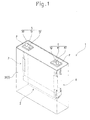
- a cell 1 includes a cell case (case) 3, a power generating element 2 serving as an electrode assembly in which a positive electrode plate 20a and a negative electrode plate 20b holding a separator 20c therebetween are flatly wound and housed in the cell case 3, a pair of external terminals 4 and 5 (hereinafter referred to as the positive-electrode external terminal 4 and the negative-electrode external terminal 5) provided for external connection, a pair of current collecting members 6 and 7 (hereinafter referred to as the positive-electrode current collecting member 6 and the negative-electrode current collecting member 7) arranged along an inner surface of the cell case 3 to connect the power generating element 2 with each of the pair of external terminals 4 and 5, and a pair of clip members 8 and 9 for coupling each of the laminated portions 21a and 21b (hereinafter referred to as the positive-electrode laminated portion 21a and the negative-electrode laminated portion 21b
- the power generating element 2 is formed by the positive electrode plate 20a and the negative electrode plate 20b flatly wound with the separator 20c held therebetween. That is, the positive electrode plate 20a, the negative electrode plate 20b and the separator 20c are all formed into a band shape and stacked to each other in the order of the positive electrode plate 20a, the separator 20c and the negative electrode plate 20b, while being aligned with one another in a longitudinal direction, thus being wound spirally.
- the length of the separator 20c in the longitudinal direction thereof is set longer than those of the positive electrode plate 20a and the negative electrode plate 20b. Accordingly, a terminal portion of the separator 20c envelops the outermost positive electrode plate 20a or negative electrode plate 20b (positive electrode plate 20a in the present embodiment). That is, the positive electrode plate 20a, the separator 20c and the negative electrode plate 20b, excluding the outermost circumference of the power generating element 2, are stacked on each other in keeping with the order thereof.
- the separator 20c extending out of the terminal portions (end portions on the opposite side ot leading end portions which are volute tongues) of the positive electrode plate 20a and the negative electrode plate 20b is wound larger in the number of turns than the positive electrode plate 20a and the negative electrode plate 20b, and therefore, arranged on the outermost circumference of the power generating element 2.
- the positive electrode plate 20a is formed by coating a positive-electrode active material on a metal foil.
- a positive-electrode lead portion L1 composed of a positive-electrode active material uncoated region (metal foil) is formed in one end portion of the positive electrode plate 20a in the width direction thereof, and a positive-electrode active material coated region (hereinafter referred to as the positive-electrode coated region) A is formed in the positive electrode plate 20a, excluding the one end portion thereof, so as to adjoin the positive-electrode lead portion L1.
- the negative electrode plate 20b is formed by coating a negative electrode active material on a metal foil.
- a negative-electrode lead portion L2 composed of a negative-electrode active material uncoated region is formed in the other end portion of the negative electrode plate 20b in the width direction thereof, and a negative-electrode active material coated region (hereinafter referred to as the negative-electrode coated region) B is formed in the negative electrode plate 20b, excluding the other end portion thereof, so as to adjoin the negative-electrode lead portion L2.
- the negative-electrode coated region a negative-electrode active material coated region
- the positive-electrode coated region A is formed, with the positive electrode plate 20a and the negative electrode plate 20b holding the separator 20c therebetween, so that both edges E1 and E1 of the positive-electrode coated region A in the width direction thereof overlap with the negative-electrode coated region B. That is, the negative-electrode coated region B is formed so as to protrude outward from both edges E1 and E1 of the positive-electrode coated region A in the width direction thereof.
- the positive electrode plate 20a and the negative electrode plate 20b are stacked on each other, while being displaced form each other in the width direction, so that one end portion (positive-electrode lead portion L1) of the positive electrode plate 20a and the other end portion (negative-electrode lead portion L2) of the negative electrode plate 20b do not overlap with a counterpart electrode plate (the negative electrode plate 20b for the positive electrode plate 20a and the positive electrode plate 20a for the negative electrode plate 20b), and wound spirally.
- the power generating element 2 is provided with a laminated part of only the positive electrode plate 20a (positive-electrode lead portion L1) in one end portion in the width direction, whereas the power generating element 2 is provided with a laminated part of only the negative electrode plate 20b (negative-electrode lead portion L2) in the other end portion in the width direction.
- the positive-electrode external terminal 4 is electrically connected to the laminated part of only the positive electrode plate 20a (positive-electrode lead portion L1)
- the negative-electrode external terminal 5 is electrically connected to the laminated part of only the negative electrode plate 20b (negative-electrode lead portion L2).
- the laminated part of the positive-electrode lead portion L1 takes the form of a flat annular shape when viewed from the winding center direction of the power generating element 2.
- the laminated part of the negative-electrode lead portion L2 also takes the form of a flat annular shape when viewed from the winding center direction.
- the power generating element 2 is housed in the cell case 3 with the long axis direction (cross-sectional long axis direction) of the power generating element 2 as viewed from the winding center direction facing up and down.
- the cell case 3 is provided, with a case body 30 having a rectangular box shape one surface of which is open, and a cover plate 31 for sealing the open portion of the case body 30.
- the positive-electrode current collecting member 6 and the negative-electrode current collecting member 7 are housed in the cell case 3.
- the cell case 3 is filled with an electrolyte solution.
- the positive-electrode external terminal 4 and the negative-electrode external terminal 5 share a common configuration and are disposed outside the cell case 3 (cover plate 31), so as to be symmetrical to each other with respect to the cell case 3 (cover plate 31).
- the positive-electrode external terminal 4 is connected to the positive-electrode current collecting member 6, and the negative-electrode external terminal 5 is connected to the negative-electrode current collecting member 7.
- the positive-electrode external terminal 4 is provided with a terminal part 40 for electrically connecting and fixing a connection object (not illustrated), such as a cable or a bus bar, a connecting fitting 41 arranged on an outer surface of the cell case 3 (cover plate 31) and made of a reed-shaped metal plate, and connecting means 42 for connecting the positive-electrode current collecting member 6 with the connecting fitting 41.
- the negative-electrode external terminal 5 has the same configuration as that of the positive-electrode external terminal 4.
- the terminal parts 40 and 50 are composed of male-threaded members, and each terminal part is outwardly inserted through one end portion of each of the connecting fittings 41 and 51 in the longitudinal direction thereof.
- the other end portion of each of the connecting fittings 41 and 51 in the longitudinal direction thereof is fixed to the cover plate 31 by each of connecting means (for example, rivets inserted through the cover plate 31) 42 and 52.
- the positive-electrode current collecting member 6 and the negative electrode current collecting member 7 are disposed so as to be symmetrical to each other with respect to the cell case 3 (case body 30) inside the cell case 3 (case body 30). Note that the positive-electrode current collecting member 6 and the negative-electrode current collecting member 7 are the same in configuration. Hence, hereinafter, the positive-electrode current collecting member 6 will be described as a representative of the positive-electrode current collecting member 6 and the negative-electrode current collecting member 7.
- the positive-electrode current collecting member 6 is provided with an external terminal connecting portion 600 that is electrically connected to the terminal part 40 arranged outside the cell case 3 and that serves as a first portion, and a power generating element connecting portion 601 that extends out of an end portion of the external terminal connecting portion 600 and is connected to the positive-electrode laminated portion 21a of the positive electrode plate 20a of the power generating element 2 and that serves as a second portion and an electrode assembly connecting portion.
- the positive-electrode current collecting member 6 is an integrally-molded member composed of the external terminal connecting portion 600 and the power generating element connecting portion 601 by processing a thin metal plate.
- the metal plate is of a band shape. Accordingly, the length of the metal plate in the longitudinal direction thereof as a first direction is longer than the length of the metal plate in the width direction thereof as a second direction orthogonal to the longitudinal direction.
- a central portion of the power generating element connecting portion 601 in the width direction thereof orthogonal to the extending direction thereof is divided at a halfway position of power generating element connecting portion 601 in the extending direction, thereby forming a pair of divided portions 601b and 601c. Accordingly, the power generating element connecting portion 601 is provided with the pair of divided portions 601b and 601c between the base portion 601a and the leading end portion 601h.
- One divided portion 601b is provided with a twisted portion 601d twisted in the width direction of the power generating element connecting portion 601, a reverse-twisted portion 601d' likewise twisted in the width direction of the power generating element connecting portion 601 but in a direction opposite to the twisting direction of the twisted portion 60d, and an insertion portion 601f provided in continuity with the twisted portion 601d and the reverse-twisted portion 601d'.
- the other divided portion 601c is provided with a twisted portion 601e twisted in the width direction of the power generating element connecting portion 601, a reverse-twisted portion 601e' likewise twisted in the width direction of the power generating element connecting portion 601 but in a direction opposite to the twisting direction of the twisted portion 601e, and an insertion portion 601g provided in continuity with the twisted portion 601e and the reverse-twisted portion 601e'.
- the insertion portions 601f and 601g are formed so that surfaces thereof face each other.
- the insertion portions 601f and 601g are formed so as to be insertable into the winding center 22a of the positive electrode plate 20a of the power generating element 2.
- each of the pair of divided portions 601b and 601c is twisted from the central portion side of the power generating element connecting portion 601 in the width direction thereof toward the end portion side of the power generating element connecting portion 601 in the width direction thereof. Accordingly, it is possible to more easily insert the insertion portions 601f and 601g of the pair of divided portions 601b and 601c into the winding center 22a of the positive electrode plate 20a and into the winding center 22b of the negative electrode plate 20b of the power generating element 2 than in a configuration in which both of the pair of divided portions 601b and 601c are twisted in the same direction, as illustrated in Fig.
- both of the pair of divided portions 601b and 601c are twisted in the same direction means that either one of the pair of divided portions 601b and 601c is twisted from the central portion side of the power generating element connecting portion 601 in the width direction thereof toward the end portion side of the power generating element connecting portion 601 in the width direction thereof, and the other one of the pair of divided portions 601b and 601c is twisted from the end portion side of the power generating element connecting portion 601 in the width direction thereof toward the central portion side of the power generating element connecting portion 601 in the width direction thereof.
- Fig. 6(a) illustrates a configuration in which the divided portion 601b is twisted from the end portion side of the power generating element connecting portion 601 in the width direction thereof toward the central portion side of the power generating element connecting portion 601 in the width direction thereof.
- the positive-electrode current collecting member 6 is provided with the external terminal connecting portion (first portion) 600 connected to the positive-electrode external terminal 4, and the power generating element connecting portion (second portion) 601 extending out of the other end portion of the external terminal connecting portion 600 and connected to the power generating element 2, as illustrated in Figs. 3 and 5 .
- the power generating element connecting portion 601 is bent with respect to the external terminal connecting portion 600. That is, the external terminal connecting portion 600 and the power generating element connecting portion 601 intersect with each other. In the present embodiment, the connecting portions intersect with each other at an angle of 90 or nearly 90 degrees.
- the power generating element connecting portion 601 is provided with a base portion 601a connected to the other end portion of the external terminal connecting portion 600, a pair of twisted portions 601d and 601e connected abreast to the other end portion of the base portion 601a, a pair of insertion portions 601f and 601g respectively connected to the other end portion of each of the pair of twisted portions 601d and 601e, a pair of reverse-twisted portions 601d' and 601e' respectively connected to the other end portion of each of the pair of insertion portions 601f and 601g, and a leading end portion 601h connected to the other end portion of each of the pair of reverse-twisted portions 601d' and 601e'.
- a combination of the twisted portion 601d, the insertion portion 601f and the reverse-twisted portion 601d' constitutes one divided portion 601b
- a combination of the twisted portion 601e, the insertion portion 601g and the reverse-twisted portion 601e' constitutes the other divided portion 601c
- one end portions of the pair of divided portions 601b and 601c are coupled with each other by the base portion 601a
- the other end portions of the pair of divided portions 601b and 601c are coupled with each other by the leading end portion 601h.
- the base portion 601a, the twisted portions 601d and 601e, the insertion portions 601f and 601g, the reverse-twisted portions 601d' and 601e', and the leading end portion 601h each are of a plate-like shape.
- the twisted portions 601d and 601e are twisted at an angle of 90 or nearly 90 degrees. That is, the twisted portions 601d and 601e are twisted so that one end portions and the other end portions thereof intersect with each other at an angle of 90 or nearly 90 degrees. Accordingly, the base portion 601a and the insertion portions 601f and 601g are orthogonal or nearly orthogonal to each other.
- Each of the reverse-twisted portions 601d' and 601e' is also twisted at an angle of 90 or nearly 90 degrees. That is, one end portions and the other end portions of the reverse-twisted portions 601d' and 601e' are also twisted so as to intersect with each other at an angle of 90 or nearly 90 degrees. Consequently, the insertion portions 601f and 601g and the leading end portion 60 is are orthogonal or nearly orthogonal to each other. In addition, the base portion 601a and the leading end portion 601h are flush or nearly flush with each other.
- the power generating element connecting portion 601 is arranged along a long axis direction (cross-sectional long axis direction) of the power generating element 2, and disposed so as to face an end face of the power generating element 2. Consequently, the base portion 601a and the leading end portion 601h of the power generating element connecting portion 601 face the end face of the power generating element 2. More specifically, the base portion 601a and the leading end portion 601h face the end face of the power generating element 2 in abutment or nearly in abutment with the end face or at a predetermined interval between each of the base portion 601a and the leading end portion 601h and the end face of the power generating element 2.
- Such a positive-electrode current collecting member 6 as described above is fabricated in the following manner. First, a score penetrating through both the front and rear sides of the above-described metal plate is formed therein along the longitudinal direction thereof, excluding at least both end portions of the metal plate in the longitudinal direction thereof. Consequently, a pair of divided portions 601b and 601c aligned in the width direction is formed. Next, each of the pair of divided portions 601b and 601c is twisted in the width direction, so that the rest of the divided portion excluding both end portions thereof in the longitudinal direction intersects with a surface of the metal plate in each of the pair of divided portions 601b and 601c.
- one end portion (one region in which the metal plate is not divided) of the metal plate in the longitudinal direction thereof serves as the external terminal connecting portion 600 and the base portion 601a.
- the other end portion (the other region in which the metal plate is not divided) of the metal plate in the longitudinal direction thereof serves as the leading end portion 601h.
- Both end portions of each of the divided portions 601b and 601c in the longitudinal direction thereof serve as the twisted portions 601d and 601e and the reverse-twisted portions 601d' and 601e'.
- Portions of the divided portions 601b and 601c excluding both end portions of each thereof in the longitudinal direction serve as the insertion portions 601f and 601g.
- the positive-electrode current collecting member 6 is fabricated in this manner.
- the clip member 8 for the positive-electrode current collecting member 6 is formed by performing double-bending work on a metal plate, and is provided according to places of connection (insertion portions 601f and 601g) with the power generating element 2.
- the clip member 8 is provided with a pair of opposed pieces 80a and 80b opposed to each other with the bending ridge line of the clip member 8 as a boundary.
- the length of the clip member 8 in a direction in which the bending ridge lines of the pair of opposed pieces 80a and 80b extend is set substantially the same as that of the power generating element connecting portion 601.
- the clip member 9 for the negative-electrode current collecting member 7 has the same configuration as that of the clip member 8 of the positive-electrode current collecting member 6.
- the external terminal connecting portion 600 of the positive-electrode current collecting member 6 is fixed to the positive-electrode external terminal 4.
- the external terminal connecting portion 600 is fixed to the cover plate 31 by connecting means 42 and electrically connected to the connecting fitting 41 of the positive-electrode external terminal 4.
- a rivet is adopted as the connecting means 42.
- the cell case 3 is formed of a conductive metal material. Accordingly, insulating gaskets P having electrical insulating properties are arranged between the external terminal connecting portion 600 of the positive-electrode current collecting member 6 and the cover plate 31 and between the connecting fitting 41 and the cover plate 31.
- the negative-electrode current collecting member 7 is the same in this regard as the positive-electrode current collecting member 6.
- the insertion portions 601f and 601g of the positive-electrode current collecting member 6 and the power generating element 2 are ultrasonic-welded to each other.
- the insertion portions 601f and 601g are inserted into the winding center 22a of the positive electrode plate 20a of the power generating element 2, the insertion portions 601f and 601g and the positive-electrode laminated portion 21a of the power generating element 2 are interposed between the pair of opposed pieces 80a and 80b of the clip member 8, and the two opposed pieces 80a and 80b are caulked so as to approach each other.
- a horn is arranged outside the power generating element 2, an anvil is arranged in the winding center 22a of the positive electrode plate 20a, and ultrasonic waves are applied to the horn. Consequently, the power generating element 2 and the insertion portions 601f and 601g are physically coupled with each other and electrically connected to each other.
- the negative-electrode current collecting member 7 is the same in this regard as the positive-electrode current collecting member 6.
- the power generating element 2 connected to the positive-electrode current collecting member 6 and the negative-electrode current collecting member 7 is then housed inside the cell case 3 with the long axis direction of the power generating element 2 as viewed from the winding center direction thereof facing up and down.
- the twisted portion 601d and the reverse-twisted portion 601d' are formed in both end portions of the insertion portion 601f in the extending direction of the power generating element connecting portion 601, and the twisted portion 601e and the reverse-twisted portion 601e' are formed in both end portions of the insertion portion 601g in the extending direction of the power generating element connecting portion 601 in the positive-electrode current collecting member 6. Accordingly, the insertion portions 601f and 601g are easy to be inserted into the winding center 22a of the positive electrode plate 20a.
- the twisted portion 601d and the reverse-twisted portion 601d' are formed in both end portions of the insertion portion 601f
- the twisted portion 601e and the reverse-twisted portion 601e' are formed in both end portions of the insertion portion 601g. Consequently, any corners and end faces (angular portions) are not present in two end portions each of the insertion portions 601f and 601g. Accordingly, when the insertion portions 601f and 601g are inserted into the winding center 22a of the positive electrode plate 20a of the power generating element 2, it is possible to suitably prevent such corners or end faces (angular portions) from scraping against an inner surface of the positive-electrode laminated portion 21a and causing damage to the inner surface.
- the negative-electrode current collecting member 7 is the same in this regard as the positive-electrode current collecting member 6.
- the cell 1 in accordance with the present embodiment it is possible to arrange the horn outside the power generating element 2, arrange the anvil in the winding center 22a of the power generating element 2, and ultrasonic-weld the power generating element 2 and the insertion portions 601f and 601g under the condition of the insertion portions 601f and 601g of the positive-electrode current collecting member 6 being inserted into the winding center 22a of the positive electrode plate 20a of the power generating element 2. Consequently, it is possible to increase the connection strength of the insertion portions 601f and 601g (positive-electrode current collecting member 6) and the power generating element 2.
- any portions (constrictions) narrower than the external terminal connecting portion 600 are not formed in a joint of the external terminal connecting portion 600 and the power generating element connecting portion 601. Consequently, the positive-electrode current collecting member 6 is free of cross sectional change throughout a path from the external terminal connecting portion 600 to the power generating element connecting portion 601, and therefore, does not vary in resistance.
- the negative-electrode current collecting member 7 is the same in this regard as the positive-electrode current collecting member 6.
- the positive-electrode current collecting member 6 is arranged so that the base portion 601a faces an end face (an end face of the power generating element 2 taking the form of a flat annular shape when viewed from the direction of the winding center 22a) of the power generating element 2 (positive-electrode laminated portion 21a). Accordingly, as the result of the base portion 601a abutting on the end face of the power generating element 2, it is possible to prevent the insertion portions 601f and 601g from getting too deep into the winding center 22a of the power generating element 2.
- the negative-electrode current collecting member 7 is the same in this regard as the positive-electrode current collecting member 6.
- the positive-electrode current collecting member 6 is arranged so that also the leading end portion 601h faces an end face (an end face of the power generating element 2 taking the form of a flat annular shape when viewed from the direction of the winding center 22a) of the power generating element 2 (positive-electrode laminated portion 21a). Accordingly, the above-described advantageous effect is made more prominent by this leading end portion 601h.
- one end portions of the pair of divided portions 601b and 601c are coupled with each other by the base portion 601a, and the other end portions thereof are coupled with each other by the leading end portion 601h. That is, in the positive-electrode current collecting member 6, the pair of divided portions 601b and 601c has a fixed-end structure. Accordingly, even if any external stress, such as vibration or impact, occurs in the cell 1 (in particular, even if vibration or the like occurs in the width direction of the positive-electrode current collecting member 6) with the cell 1 placed in a usage environment, a bifurcation of divided portions 601b and 601c does not become damaged.
- the pair of divided portions 601b' and 601c' has a free-end structure. Accordingly, each of the divided portions 601b' and 601c' freely vibrates. Consequently, a bifurcation of the divided portions 601b' and 601c' may become damaged, and therefore, the positive-electrode current collecting member 6' may break. In the present embodiment, however, such a problem is unlikely to occur.
- the negative-electrode current collecting member 7 is the same in this regard as the positive-electrode current collecting member 6.
- the twisted portion 601d and the reverse-twisted portion 601d' are formed in both end portions of the insertion portion 601f inserted into the winding center 22a of the power generating element 2, and the twisted portion 601e and the reverse-twisted portion 601e' are formed in both end portions of the insertion portion 601g.
- These twisted portions 601d and 601e and reverse-twisted portions 601d' and 601e' constitute extension portions extending out of both end portions of the insertion portions 601f and 601g, in such a manner as to set back from outer surfaces (surfaces of contact with an inner surface of the winding center 22a of the power generating element 2) of the insertion portions 601f and 601g.
- the insertion portions 601f and 601g do not cause any damage to the inner surface of the positive-electrode laminated portion 21a.
- the negative-electrode current collecting member 7 is the same in this regard as the positive-electrode current collecting member 6.
- the electric storage device is not limited to a cell.
- the electric storage device may be a capacitor, such as an electric double layer capacitor.
- the power generating element connecting portion (second portion) 601 of the positive-electrode current collecting member 6 is not limited to the above-described embodiment.
- the power generating element connecting portion 601 of the positive-electrode current collecting member 6 may be provided with a pair of divided portions 601b and 601c formed by dividing (decoupling) a central portion of the power generating element connecting portion 601 in the width direction orthogonal to the extending direction from a halfway position to a leading end of the power generating element connecting portion 601 in the extending direction thereof.
- the twisted portion 601d may be formed in one end portion of the insertion portion 601f in the extending direction of the power generating element connecting portion 601
- the twisted portion 601e may be formed in one end portion of the insertion portion 601g in the extending direction of the power generating element connecting portion 601.
- the positive-electrode current collecting member 6 illustrated in Fig. 7 is provided with an external terminal connecting portion (first portion) 600 connected to the positive-electrode external terminal 4, and a power generating element connecting portion (second portion) 601 extending out of the other end portion of the external terminal connecting portion 600 and connected to the power generating element 2.
- the power generating element connecting portion 601 is bent with respect to the external terminal connecting portion 600.
- the external terminal connecting portion 600 and the power generating element connecting portion 601 intersect with each other. In Fig. 7 , the connecting portions intersect with each other at an angle of 90 or nearly 90 degrees.
- the power generating element connecting portion 601 is provided with a base portion 601a connected to the other end portion of the external terminal connecting portion 600, a pair of twisted portions 601d and 601e connected abreast to the other end portion of the base portion 601a, and a pair of insertion portions 601f and 601g connected to the respective other end portions of the pair of twisted portions 601d and 601e.
- a combination of the twisted portion 601d and the insertion portion 601f constitutes one divided portion 601b
- a combination of the twisted portion 601e and the insertion portion 601g constitutes the other divided portion 601c
- the one end portions of the pair of divided portions 661b and 601c are coupled with each other by the base portion 601a.
- the base portion 601 a, the twisted portions 601d and 601e, and the insertion portions 601f and 601g each are of a plate-like shape.
- the twisted portions 601d and 601e are twisted at an angle of 90 or nearly 90 degrees. That is, the twisted portions 601d and 601e are twisted so that one end portion and the other end portion thereof intersect with each other at an angle of 90 or nearly 90 degrees. Accordingly, the base portion 601a and the insertion portions 601f and 601g are orthogonal or nearly orthogonal to each other.
- the power generating element connecting portion 601 is arranged along a long axis direction (cross-sectional long axis direction) of the power generating element 2, and disposed so as to face an end face of the power generating element 2. Consequently, the base portion 601a of the power generating element connecting portion 601 faces the end face of the power generating element 2. More specifically, the base portion 601a faces the end face of the power generating element 2 in abutment or nearly in abutment with the end face or at a predetermined interval between the base portion 601a and the end face.
- the insertion portions 601f and 601g of the positive-electrode current collecting member 6 are made easy to be inserted into the winding center 22a of the positive electrode plate 20a of the power generating element 2. Accordingly, it is possible to arrange a horn outside the power generating element 2, arrange an anvil in the winding center 22a of the power generating element 2, and ultrasonic-weld the power generating element 2 and the insertion portions 601f and 601g under the condition of the insertion portions 601f and 601g of the positive-electrode current collecting member 6 being inserted into the winding center 22a of the positive electrode plate 20a of the power generating element 2.
- any portions (constrictions) narrower than the external terminal connecting portion 600 are not formed in a joint of the external terminal connecting portion 600 and the power generating element connecting portion 601. Consequently, the positive-electrode current collecting member 6 is free of cross sectional change throughout a path from the external terminal connecting portion 600 to the power generating element connecting portion 601, and therefore, does not vary in resistance.
- the negative-electrode current collecting member 7 may be the same in configuration as such a positive-electrode current collecting member 6 as described above (as illustrated in Fig. 7 ).
- only one combination of the twisted portion 601d and the insertion portion 601f, rather than a pair of the combinations may be provided in the power generating element connecting portion (second portion) 601 of the positive-electrode current collecting member 6.
- the power generating element connecting portion (second portion) 601 of the positive-electrode current collecting member 6 need not necessarily be provided with a pair of the divided portions 601b and 601c.
- the negative-electrode current collecting member 7 may be the same in configuration as such a positive-electrode current collecting member 6 as described above.
- the external terminal connecting portion 600 and the power generating element connecting portion 601 of the positive-electrode current collecting member 6 may intersect with each other at an angle other than 90 or nearly 90 degrees.
- the negative-electrode current collecting member 7 may be the same in configuration as such a positive-electrode current collecting member 6 as described above.
- the twisted portions 601d and 601e and the reverse-twisted portions 601d' and 601e' of the positive-electrode current collecting member 6 may be twisted at an angle other than 90 or nearly 90 degrees.
- the insertion portions 601f and 601g are not orthogonal or nearly orthogonal to the base portion 601a but are inclined therefrom. If this pair of insertion portions 601f and 601g is inclined so that the distance therebetween becomes narrower toward the power generating element 2, the pair of insertion portions 601f and 601g provides the same advantageous effect as a later-described pair of inclined portions 601i and 601j.
- the negative-electrode current collecting member 7 may be the same in configuration as such a positive-electrode current collecting member 6 as described above.
- the twisted portions 601d and 601e and the reverse-twisted portions 601d' and 601e' of the positive-electrode current collecting member 6 are formed so as to be the same in length in the extending direction of the power generating element connecting portion 601 (in the longitudinal direction of a metal plate composing the positive-electrode current collecting member 6).
- the twisted portions 601d and 601e and the reverse-twisted portions 601d' and 601e' are not limited to this configuration, however. That is, the twisted portions 601d and 601e may be formed so as to be longer or shorter than the reverse-twisted portions 601d' and 601e' in the extending direction of the power generating element connecting portion 601.
- the negative-electrode current collecting member 7 may be the same in configuration as such a positive-electrode current collecting member 6 as described above.
- the pair of twisted portions 601d and 601e of the positive-electrode current collecting member 6 are formed so as to be the same in length in the extending direction of the power generating element connecting portion 601.
- the pair of reverse-twisted portions 601d' and 601e' of the positive-electrode current collecting member 6 is formed so as to be the same in length in the extending direction of the power generating element connecting portion 601.
- the pair of reverse-twisted portions 601d' and 601e' is not limited to this configuration, however. That is, one of the pair of twisted portions 601d and 601e may be formed longer or shorter than the other twisted portion.
- one of the pair of reverse-twisted portions 601d' and 601e' may be formed longer or shorter than the other reverse-twisted portion.
- the negative-electrode current collecting member 7 may be the same in configuration as such a positive-electrode current collecting member 6 as described above.
- the pair of divided portions 601b and 601c of the positive-electrode current collecting member 6 is formed so as to be the same in width in the width direction of the power generating element connecting portion 601 (in the width direction of a metal plate composing the positive-electrode current collecting member 6).
- the pair of divided portions 601b and 601c is not limited to this configuration, however.
- One of the pair of divided portions 601b and 601c may be formed larger or smaller in width than the other divided portion.
- the negative-electrode current collecting member 7 may be the same in configuration as such a positive-electrode current collecting member 6 as described above.
- the positive-electrode current collecting member 6 and the negative-electrode current collecting member 7 may be different in configuration from each other.
- the positive-electrode current collecting member 6 may be formed as illustrated in Fig. 5
- the negative-electrode current collecting member 7 may be formed as illustrated in Fig. 7 , thus making the positive-electrode current collecting member 6 and the negative-electrode current collecting member 7 different in configuration from each other.
- either one of the positive-electrode current collecting member 6 and the negative-electrode current collecting member 7 may be a current collecting member having a conventional configuration.
- the clip members 8 and 9 are not essential. In an ultrasonic welding process, it is possible to perform welding without using the clip members 8 and 9. However, use of the clip members 8 and 9 keeps a horn from coming into direct contact with the power generating element (metal foil) 2. Consequently, it is possible to prevent the metal foil portions (positive electrode plate 20a and negative electrode plate 20b) of the power generating element 2 from fracturing in the ultrasonic welding process. It is therefore preferable to use the clip members 8 and 9.
- the insertion portions 601f and 601g may be inserted into the winding center 22a of the positive electrode plate 20a of the power generating element 2, so as to have contact with an outer surface of the clip member 8, and the place of contact may be ultrasonic-welded.
- the negative-electrode laminated portion 21b side may be configured in the same as such a positive-electrode laminated portion 21a side as described above.
- metal plates 10 and 11 are tabular and arranged on a side of the positive-electrode laminated portion 21a or the negative-electrode laminated portion 21b with which a horn has contact (outside the power generating element 2 in Fig. 8 ). That is, the horn, the metal plate 10, the positive-electrode laminated portion 21a, the positive-electrode current collecting member 6, and an anvil are arranged in this order from outside the power generating element 2 on the positive electrode plate 20a side, and an ultrasonic welding process is carried out.
- the horn, the metal plate 11, the negative-electrode laminated portion 21b, the negative-electrode current collecting member 7, and the anvil are arranged in this order from outside the power generating element 2 on the negative electrode plate 20b side, and an ultrasonic welding process is carried out.
- the metal plates 10 and 11 may be of such a size as not to allow the horn to come into direct contact with the power generating element (metal foil) 2.
- the cell 1' described in the foregoing Background Art paragraph is designed, in consideration of dimensional tolerances, the expansion of the power generating element 2', and the like, so that a gap is formed between the power generating element 2' and the cell case 3' in the vertical and width directions of the power generating element 2'. Accordingly, even if extraneous stress, such as vibration or impact, occurs in the cell 1' in the vertical direction of the power generating element 2', the breakage of the power generating element 2' due to wobbling caused by vibration or impact or expansion/contraction stress is less likely to occur.
- the positive electrode plate 20a' and the negative electrode plate 20b' of the power generating element 2' may bend in the vicinity of the current collecting members 6' and 7' (electrode assembly connecting portions 601' and 701'), and the bent portion may undergo great stress when the positive electrode plate 20a' and the negative electrode plate 20b' of the power generating element 2' are bundled. Consequently, the positive electrode plate 20a' and the negative electrode plate 20b' of the power generating element 2' may fracture in some cases. Accordingly, there is a demand for a current collecting member adapted not to fracture the positive electrode plate and the negative electrode plate of a power generating element, as well as a current collecting member capable of increasing the strength of connection with a power generating element. This is also true for a current collecting member in a capacitor (electric double layer capacitor, or the like).
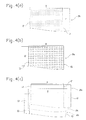
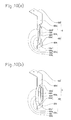
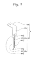
- each of the pair of insertion portions 601f and 601g of the positive-electrode current collecting member 6 may be provided with an inclined surface inclined so as to approach a counterpart insertion portion on the leading end side thereof in the insertion direction. More specifically, at least an end portion of the pair of insertion portions 601f and 601g on the power generating element 2 side is bent toward a counterpart insertion portion to be formed into inclined portions 601i and 601j.
- the other surfaces of at least end portions of the insertion portions 601f and 601g on the power generating element 2 side are inclined so as to be closer to counterpart insertion portions toward a side on which the power generating element 2 is arranged. Accordingly, the insertion portions 601f and 601g are easier to insert into the winding center 22a of the positive electrode plate 20a than the insertion portions 601f and 601g of the above-described embodiment.
- the inclined portion 601i is provided in one insertion portion 601f and the inclined portion 601j is provided in the other insertion portion 601g, an anvil is not inserted further inward beyond the positions of those inclined portions. Accordingly, the anvil is not inserted too deep into the winding center 22a of the positive electrode plate 20a of the power generating element 2. Thus, there is no possibility of the winding center 22a of the positive electrode plate 20a of the power generating element 2 becoming damaged and causing internal short-circuits. As described above, the inclined portions 601i and 601j can also be utilized in the positioning of an anvil in the winding center 22a of the positive electrode plate 20a.
- the negative-electrode current collecting member 7 may be configured in the same way as such a positive-electrode current collecting member 6 as described above (as illustrated in each of Figs. 9(a), 9(b) , 10(a) , web) and 11).
- the positive-electrode current collecting member 6 illustrated in Figs. 9(a) and 9(b) corresponds to the positive-electrode current collecting member 6 illustrated in Fig. 5 .
- the positive-electrode current collecting member 6 illustrated in Fig. 10(a) corresponds to the positive-electrode current collecting member 6 illustrated in Fig. 6(a) .
- the positive-electrode current collecting member 6 illustrated in Fig. 10(b) corresponds to the positive-electrode current collecting member 6 illustrated in Fig. 6(b) .
- the positive-electrode current collecting member 6 illustrated in Fig. 11 corresponds to the positive-electrode current collecting member 6 illustrated in Fig. 7 .
Abstract
Description
- The present invention relates to an electric storage device provided with a current collecting member. More particularly, the present invention relates to a current collecting member for connecting an electrode assembly and an external terminal to each other in the electric storage device. The present invention also relates to a method for manufacturing the current collecting member.
- In recent years, a rechargeable and dischargeable electric storage device has been employed as a power source of various types of equipment. Note that in the present specification, "electric storage device" is a conceptual wording that encompasses both cells (lithium-ion battery cell, nickel-metal hydride battery cell, and the like) and capacitors (electric double layer capacitor, and the like).
- As illustrated in
Figs. 12(a), 12(b) and13 , a cell is generally configured by electrically connecting a power generatingelement 2' housed in acell case 3' and an external terminal 4' provided for external connection through a current collecting member 6', and electrically connecting the power generatingelement 2' and an external terminal 5' through acurrent collecting member 7', thereby enabling an electric current to be turned on between the power generatingelement 2' and a pair of the external terminals 4' and 5'. - More specifically, a cell 1' is provided with a
cell case 3', a power generatingelement 2' in which apositive electrode plate 20a' and anegative electrode plate 20b' holding aseparator 20c' therebetween are flatly wound and housed in thecell case 3', a pair of external terminals 4' and 5' provided for external connection, a pair of current collectingmembers 6' and 7' arranged along an inner surface of thecell case 3' to connect the power generatingelement 2' with each of the pair of external terminals 4' and 5', and a pair ofclip members 8' and 9' for coupling each of the laminated portions (positive-electrode laminatedportion 21a' and negative-electrode laminatedportion 21b') of thepositive electrode plate 20a' and thenegative electrode plate 20b' of the power generatingelement 2' with each of the pair of current collectingmembers 6' and 7'. - One current collecting member 6' is provided with an external terminal connecting portion 600' electrically connected to the external terminal 4', and a pair of power generating element connecting portions 601' and 601' extending out of one end of the external terminal connecting portion 600' and connected to a positive-electrode laminated
portion 21a' of thepositive electrode plate 20a' of the power generatingelement 2'. The one current collecting member 6' is an integrally-molded member including the external terminal connecting portion 600' and the pair of power generating element connecting portions 601' and 601' by processing a metal plate. The othercurrent collecting member 7' has the same configuration as that of the one current collecting member 6', The one current collecting member 6' is connected to the one external terminal 4' at the external terminal connecting portion 600' of the current collecting member 6'. The othercurrent collecting member 7' is connected to the other external terminal 5' at the external terminal connecting portion 700' of thecurrent collecting member 7'. - In such a cell 1' as described above, each of the pair of power generating element connecting portions 601' and 601' of the one current collecting member 6', while being fitted along an outer surface of the positive-electrode laminated
portion 21a' of the power generatingelement 2', is connected to the positive-electrode laminatedportion 21a' through the clip member 8'. Likewise, each of the pair of power generating element connecting portions 701' and 701' of the othercurrent collecting member 7', while being fitted along an outer surface of the negative-electrode laminatedportion 21b' of the power generatingelement 2', is connected to the negative-electrode laminatedportion 21b' through theclip member 9'. Consequently, in the cell 1' described above, it is possible to take out the generated power of the power generatingelement 2' from the external terminals 4' and 5' through the current collectingmembers 6' and 7' (see, for example, Patent Document 1). - Incidentally, in such a cell 1' as described above, the positive-electrode laminated
portion 21a' and the power generating element connecting portion 601' are clamped with the clip member 8', a horn (not illustrated) fitted on an oscillator is inserted into an inner portion (hereinafter referred to as "winding center") 22a' of the power generatingelement 2' close to thepositive electrode plate 20a', an anvil (not illustrated) is arranged outside the power generatingelement 2', the positive-electrode laminatedportion 21a' and the power generating element connecting portion 601' are sandwiched by the horn and the anvil, and ultrasonic waves are applied to the horn (ultrasonic welding), thereby connecting together the power generatingelement 2' and the power generating element connecting portion 601' (current collecting member 6'), as illustrated inFig. 12 . The othercurrent collecting member 7' is the same in this regard as the one current collecting member 6'. - Here, the
positive electrode plate 20a', thenegative electrode plate 20b' and theclip members 8' and 9' are formed of a thin metal foil and are, therefore, excellent in energy transfer efficiency. Consequently, ultrasonic waves oscillated from the horn inserted in the inner portion (winding center 22a' orwinding center 22b') of the power generatingelement 2' are transferred from the clip member 8' to thepositive electrode plate 20a' and from theclip member 9' to thenegative electrode plate 20b', thus fusing thepositive electrode plate 20a', thenegative electrode plate 20b' and theclip members 8' and 9' from inside the power generatingelement 2'. Accordingly, it is possible to efficiently weld thepositive electrode plate 20a' and the clip member 8' to each other, and thenegative electrode plate 20b' and theclip member 9' to each other. -
- Patent Document 1: Japanese Patent Application Laid-Open No.
2003-346770 - However, the power generating
element 2' is configured such that thepositive electrode plate 20a' and thenegative electrode plate 20b' holding theseparator 20c' therebetween are wound flatly and closely, and therefore, the inner portions (winding centers 22a' and 22b') of the power generatingelement 2' are narrow. Thus, horns which can be inserted into thewinding centers 22a' and 22b' are limited in size and shape. Accordingly, it is difficult to insert horns into thewinding centers 22a' and 22b' at a correct angle. Consequently, the strength of weld between the power generatingelement 2' and the current collecting member 6' (power generating element connecting portion 601') and between the power generatingelement 2' and thecurrent collecting member 7' (power generating element connecting portion 701') is liable to instability. Accordingly, there is a demand for a current collecting member capable of increasing the strength of connection with a power generating element. This is also true for a current collecting member in a capacitor (electric double layer capacitor, or the like). - Hence, in view of the above-described circumstances, it is an object of the present invention to provide an electric storage device provided with a current collecting member capable of increasing the strength of connection with an electrode assembly. It is another object of the present invention to provide a method for manufacturing such a current collecting member.
- According to the present invention, there is provided an electric storage device, which includes:
- a case;
- an electrode assembly housed in the case and including a positive electrode plate and a negative electrode plate which are wound together while being isolated from each other;
- an external terminal arranged outside the case; and
- a current collecting member arranged inside the case to electrically connect the electrode assembly with the external terminal,
- wherein the current collecting member includes:
- a first portion including a first end portion and a second end portion and electrically connected to the external terminal; and
- a second portion extending out of the second end portion of the first portion and electrically connected to the electrode assembly, and
- and the second portion includes:
- a base portion including a first end portion and a second end portion, the first end portion being connected to the second end portion of the first portion;
- a twisted portion including a first end portion and a second end portion, the first end portion being connected to the second end portion of the base portion; and
- an insertion portion including a first end portion and a second end portion, the first end portion being connected to the second end portion of the twisted portion, the insertion portion being inserted into a winding center of the electrode assembly and electrically connected to the electrode assembly.
- Here, the electric storage device according to the present invention may have a configuration in which:
- the second portion further includes:
- a reverse-twisted portion twisted in a direction opposite to the twisting direction of the twisted portion and including a first end portion and a second end portion, the first end portion being connected to the second end portion of the insertion portion; and
- a leading end portion including a first end portion, the first end portion being connected to the second end portion of the reverse-twisted portion.
- In addition, the electric storage device according to the present invention may have a configuration in which:
- a pair of combinations each including the twisted portion, the insertion portion and the reverse-twisted portion is provided at intervals in parallel to one another, and
- the leading end portion couples the second end portions of the pair of reverse-twisted portion with each other.
- Yet additionally, the electric storage device according to the present invention may have a configuration in which:
- a pair of combinations each including the twisted portion and the insertion portion is provided at intervals in parallel to each other.
- Still additionally, the electric storage device according to the present invention may have a configuration in which:
- the twisted portion is twisted at an angle of 90 or approximately 90 degrees, so that the base portion and the insertion portion are orthogonal or nearly orthogonal to each other.
- Still additionally, the electric storage device according to the present invention may have a configuration in which:
- the twisted portion is twisted at an angle of 90 or approximately 90 degrees, so that the base portion, and the insertion portion are orthogonal or nearly orthogonal to each other, and
- the reverse-twisted portion is twisted at an angle of 90 or approximately 90 degrees in a direction opposite to the twisting direction of the twisted portion, so that the insertion portion and the leading end portion are orthogonal or nearly orthogonal to each other and that the base portion and the leading end portion are flush or nearly flush with each other.
- Still additionally, the electric storage device according to the present invention may have a configuration in which:
- the current collecting member is arranged so that the base portion faces an end face of the electrode assembly.
- Still additionally, the electric storage device according to the present invention may have a configuration in which:
- the current collecting member is arranged so that the base portion and the leading end portion face an end face of the electrode assembly.
- Still additionally, the electric storage device according to the present invention may have a configuration in which:
- each of the pair of insertion portions is provided with, on the leading end side of the insertion portion in the insertion direction thereof, an inclined surface inclined so as to approach a counterpart insertion portion.
- In addition, according to the present invention, there is provided an electric storage device, which includes
- a case;
- an electrode assembly in which a positive electrode plate and a negative electrode plate are flatly wound, while being isolated from each other, and housed in the case;
- a pair of external terminals provided for external connection; and
- a pair of current collecting members arranged along an inner surface of the case to electrically connect the electrode assembly and each of the pair of external terminals,
- wherein at least one of the pair of current collecting members includes an external terminal connecting portion arranged along an inner surface of the case, and an electrode assembly connecting portion extending out of an end portion of the external terminal connecting portion and connected to a laminated portion of the positive electrode plate or a laminated portion of the negative electrode plate of the electrode assembly, and is a current collecting member in which the external terminal connecting portion and the electrode assembly connecting portion are integrally molded by processing a metal plate,
- a central portion of the electrode assembly connecting portion in the width direction thereof orthogonal to the extending direction thereof is divided, thereby forming in the electrode assembly connecting portion a pair of divided portions,
- each of the pair of divided portions includes:
- a twisted portion twisted in the width direction of the electrode assembly connecting portion; and
- an insertion portion provided in continuity with the twisted portion, the insertion portion is formed so that surfaces of the insertion portions face each other, and is inserted into a winding center of the positive electrode plate or the negative electrode plate of the electrode assembly, and the insertion portion is electrically connected to the laminated portion of the positive electrode plate or the laminated portion of the negative electrode plate of the electrode assembly.
- In addition, according to the present invention, there is provided a method for manufacturing a current collecting member, which includes the steps of
providing a metal plate having a length in a first direction orthogonal to a second direction longer than a length in the second direction;
forming a score along the first direction in the metal plate, excluding at least both end portions thereof in the first direction, thereby forming a pair of divided portions lining up in the second direction; and
twisting each of the divided portions in the second direction, so that the rest of each of the divided portions excluding both end portions in the first direction intersects with a surface of the metal plate in each of the divided portions. - As described above, according to the electric storage device in accordance with the present invention, it is possible to increase the connection strength of the electrode assembly and the current collecting member.
-
-
Fig. 1 is an overall perspective view of a cell according to one embodiment of the present invention. -
Fig. 2 is a partially exploded perspective view of the cell according to the embodiment. -
Fig. 3 is an exploded perspective view of the cell according to the embodiment. -
Figs. 4 are explanatory views of a power generating element according to the embodiment, whereinFig. 4(a) is a partial plan view used to describe respective regions formed on a positive electrode plate composing the power generating element,Fig. 4(b) is a partial plan view used to describe respective regions formed on a negative electrode plate composing the power generating element, andFig. 4(c) is an explanatory drawing used to describe the configurational relationship between the respective regions on the positive electrode plate and the respective regions on the negative electrode plate under the condition that the positive electrode plate illustrated inFig. 4(a) and the negative electrode plate illustrated inFig. 4(b) together hold a separator therebetween. -
Fig. 5 illustrates a current collecting member according to the embodiment. -
Figs. 6 illustrate modified examples of the current collecting member according to the embodiment, whereinFig. 6(a) is a figure illustrating that one of a pair of divided portions of the current collecting member is twisted from the central portion side of a power generating element connecting portion in the width direction thereof toward the end portion side of the power generating element connecting portion in the width direction thereof, and the other divided portion is twisted from the end portion side of the power generating element connecting portion in the width direction thereof toward the central portion side of the power generating element connecting portion in the width direction thereof, andFig. 6(b) is a figure illustrating that both of the pair of divided portions are twisted from the end portion side of the current collecting member in the width direction thereof toward the central portion side of the power generating element connecting portion in the width direction thereof. -
Fig. 7 illustrates a current collecting member according to another embodiment of the present invention. -
Fig. 8 is an exploded perspective view of a cell according to another embodiment of the present invention, wherein the cell uses a metal plate in place of a clip member. -
Figs. 9 illustrate a modified example of the current collecting member illustrated inFig. 5 , whereinFig. 9(a) is a perspective view of the current collecting member andFig. 9(b) is a partially enlarged view of an electrode assembly connecting portion taken from below the electrode assembly connecting portion. -
Figs. 10 illustrate a current collecting member according to yet another embodiment of the present invention, whereinFig. 10(a) illustrates a modified example of the current collecting member illustrated inFig. 6(a) , andFig. 10(b) illustrates a modified example of the current collecting member illustrated inFig. 6(b) . -
Fig. 11 illustrates a modified example of the current collecting member illustrated inFig. 7 . -
Figs. 12 illustrate a conventional cell, whereinFig. 12(a) is an overall perspective view andFig. 12(b) is a partially exploded perspective view. -
Fig. 13 is an exploded perspective view illustrating a coupling structure of a power generating element and a current collecting member according to the conventional cell. - Hereinafter, a cell which is one embodiment of an electric storage device according to the present invention will be described with reference to the accompanying drawings.
- As illustrated in
Figs. 1 and3 , acell 1 according to the present embodiment includes a cell case (case) 3, apower generating element 2 serving as an electrode assembly in which apositive electrode plate 20a and anegative electrode plate 20b holding aseparator 20c therebetween are flatly wound and housed in thecell case 3, a pair ofexternal terminals 4 and 5 (hereinafter referred to as the positive-electrodeexternal terminal 4 and the negative-electrode external terminal 5) provided for external connection, a pair ofcurrent collecting members 6 and 7 (hereinafter referred to as the positive-electrodecurrent collecting member 6 and the negative-electrode current collecting member 7) arranged along an inner surface of thecell case 3 to connect thepower generating element 2 with each of the pair ofexternal terminals clip members laminated portions laminated portion 21a and the negative-electrodelaminated portion 21b) of thepositive electrode plate 20a and thenegative electrode plate 20b of thepower generating element 2 with each of the pair ofcurrent collecting members - As illustrated in
Fig. 3 , thepower generating element 2 is formed by thepositive electrode plate 20a and thenegative electrode plate 20b flatly wound with theseparator 20c held therebetween. That is, thepositive electrode plate 20a, thenegative electrode plate 20b and theseparator 20c are all formed into a band shape and stacked to each other in the order of thepositive electrode plate 20a, theseparator 20c and thenegative electrode plate 20b, while being aligned with one another in a longitudinal direction, thus being wound spirally. - The length of the
separator 20c in the longitudinal direction thereof is set longer than those of thepositive electrode plate 20a and thenegative electrode plate 20b. Accordingly, a terminal portion of theseparator 20c envelops the outermostpositive electrode plate 20a ornegative electrode plate 20b (positive electrode plate 20a in the present embodiment). That is, thepositive electrode plate 20a, theseparator 20c and thenegative electrode plate 20b, excluding the outermost circumference of thepower generating element 2, are stacked on each other in keeping with the order thereof. However, theseparator 20c extending out of the terminal portions (end portions on the opposite side ot leading end portions which are volute tongues) of thepositive electrode plate 20a and thenegative electrode plate 20b is wound larger in the number of turns than thepositive electrode plate 20a and thenegative electrode plate 20b, and therefore, arranged on the outermost circumference of thepower generating element 2. - The
positive electrode plate 20a is formed by coating a positive-electrode active material on a metal foil. As illustrated inFig. 4(a) , a positive-electrode lead portion L1 composed of a positive-electrode active material uncoated region (metal foil) is formed in one end portion of thepositive electrode plate 20a in the width direction thereof, and a positive-electrode active material coated region (hereinafter referred to as the positive-electrode coated region) A is formed in thepositive electrode plate 20a, excluding the one end portion thereof, so as to adjoin the positive-electrode lead portion L1. - The
negative electrode plate 20b is formed by coating a negative electrode active material on a metal foil. As illustrated inFig. 4(b) , a negative-electrode lead portion L2 composed of a negative-electrode active material uncoated region is formed in the other end portion of thenegative electrode plate 20b in the width direction thereof, and a negative-electrode active material coated region (hereinafter referred to as the negative-electrode coated region) B is formed in thenegative electrode plate 20b, excluding the other end portion thereof, so as to adjoin the negative-electrode lead portion L2. In addition, as illustrated inFig. 4(c) , the positive-electrode coated region A is formed, with thepositive electrode plate 20a and thenegative electrode plate 20b holding theseparator 20c therebetween, so that both edges E1 and E1 of the positive-electrode coated region A in the width direction thereof overlap with the negative-electrode coated region B. That is, the negative-electrode coated region B is formed so as to protrude outward from both edges E1 and E1 of the positive-electrode coated region A in the width direction thereof. - In addition, the
positive electrode plate 20a and thenegative electrode plate 20b are stacked on each other, while being displaced form each other in the width direction, so that one end portion (positive-electrode lead portion L1) of thepositive electrode plate 20a and the other end portion (negative-electrode lead portion L2) of thenegative electrode plate 20b do not overlap with a counterpart electrode plate (thenegative electrode plate 20b for thepositive electrode plate 20a and thepositive electrode plate 20a for thenegative electrode plate 20b), and wound spirally. - Consequently, the
power generating element 2 is provided with a laminated part of only thepositive electrode plate 20a (positive-electrode lead portion L1) in one end portion in the width direction, whereas thepower generating element 2 is provided with a laminated part of only thenegative electrode plate 20b (negative-electrode lead portion L2) in the other end portion in the width direction. In addition, the positive-electrodeexternal terminal 4 is electrically connected to the laminated part of only thepositive electrode plate 20a (positive-electrode lead portion L1), and the negative-electrodeexternal terminal 5 is electrically connected to the laminated part of only thenegative electrode plate 20b (negative-electrode lead portion L2). - As the result of the positive-electrode coated region A being formed so that both edges E1 and E1 of the positive-electrode coated region A in the width direction thereof overlap with the negative-electrode coated region B, as described above, electrocrystallization is prevented from occurring in the vicinity of edges E2 and E2 of the negative-electrode coated region B in the width direction thereof.
- Since the
power generating element 2 is flatly formed as described above, the laminated part of the positive-electrode lead portion L1 takes the form of a flat annular shape when viewed from the winding center direction of thepower generating element 2. The laminated part of the negative-electrode lead portion L2 also takes the form of a flat annular shape when viewed from the winding center direction. In addition, thepower generating element 2 is housed in thecell case 3 with the long axis direction (cross-sectional long axis direction) of thepower generating element 2 as viewed from the winding center direction facing up and down. - As illustrated in
Fig. 3 , thecell case 3 is provided, with acase body 30 having a rectangular box shape one surface of which is open, and acover plate 31 for sealing the open portion of thecase body 30. In addition to thepower generating element 2, the positive-electrodecurrent collecting member 6 and the negative-electrodecurrent collecting member 7 are housed in thecell case 3. In addition, thecell case 3 is filled with an electrolyte solution. - As illustrated in
Figs. 1 to 3 , the positive-electrodeexternal terminal 4 and the negative-electrodeexternal terminal 5 share a common configuration and are disposed outside the cell case 3 (cover plate 31), so as to be symmetrical to each other with respect to the cell case 3 (cover plate 31). In addition, the positive-electrodeexternal terminal 4 is connected to the positive-electrodecurrent collecting member 6, and the negative-electrodeexternal terminal 5 is connected to the negative-electrodecurrent collecting member 7. As illustrated inFig. 3 , the positive-electrodeexternal terminal 4 is provided with aterminal part 40 for electrically connecting and fixing a connection object (not illustrated), such as a cable or a bus bar, a connecting fitting 41 arranged on an outer surface of the cell case 3 (cover plate 31) and made of a reed-shaped metal plate, and connectingmeans 42 for connecting the positive-electrodecurrent collecting member 6 with the connectingfitting 41. The negative-electrodeexternal terminal 5 has the same configuration as that of the positive-electrodeexternal terminal 4. - The
terminal parts fittings fittings cover plate 31 by each of connecting means (for example, rivets inserted through the cover plate 31) 42 and 52. - The positive-electrode
current collecting member 6 and the negative electrode current collectingmember 7 are disposed so as to be symmetrical to each other with respect to the cell case 3 (case body 30) inside the cell case 3 (case body 30). Note that the positive-electrodecurrent collecting member 6 and the negative-electrodecurrent collecting member 7 are the same in configuration. Hence, hereinafter, the positive-electrodecurrent collecting member 6 will be described as a representative of the positive-electrodecurrent collecting member 6 and the negative-electrodecurrent collecting member 7. - As illustrated in
Fig. 3 , the positive-electrodecurrent collecting member 6 is provided with an externalterminal connecting portion 600 that is electrically connected to theterminal part 40 arranged outside thecell case 3 and that serves as a first portion, and a power generatingelement connecting portion 601 that extends out of an end portion of the externalterminal connecting portion 600 and is connected to the positive-electrodelaminated portion 21a of thepositive electrode plate 20a of thepower generating element 2 and that serves as a second portion and an electrode assembly connecting portion. The positive-electrodecurrent collecting member 6 is an integrally-molded member composed of the externalterminal connecting portion 600 and the power generatingelement connecting portion 601 by processing a thin metal plate. The metal plate is of a band shape. Accordingly, the length of the metal plate in the longitudinal direction thereof as a first direction is longer than the length of the metal plate in the width direction thereof as a second direction orthogonal to the longitudinal direction. - As illustrated in
Figs. 3 and5 , a central portion of the power generatingelement connecting portion 601 in the width direction thereof orthogonal to the extending direction thereof is divided at a halfway position of power generatingelement connecting portion 601 in the extending direction, thereby forming a pair of dividedportions element connecting portion 601 is provided with the pair of dividedportions base portion 601a and theleading end portion 601h. One dividedportion 601b is provided with atwisted portion 601d twisted in the width direction of the power generatingelement connecting portion 601, a reverse-twistedportion 601d' likewise twisted in the width direction of the power generatingelement connecting portion 601 but in a direction opposite to the twisting direction of the twisted portion 60d, and aninsertion portion 601f provided in continuity with thetwisted portion 601d and the reverse-twistedportion 601d'. The other dividedportion 601c is provided with atwisted portion 601e twisted in the width direction of the power generatingelement connecting portion 601, a reverse-twistedportion 601e' likewise twisted in the width direction of the power generatingelement connecting portion 601 but in a direction opposite to the twisting direction of the twistedportion 601e, and aninsertion portion 601g provided in continuity with the twistedportion 601e and the reverse-twistedportion 601e'. Theinsertion portions insertion portions center 22a of thepositive electrode plate 20a of thepower generating element 2. - Here, in the present embodiment, each of the pair of divided
portions element connecting portion 601 in the width direction thereof toward the end portion side of the power generatingelement connecting portion 601 in the width direction thereof. Accordingly, it is possible to more easily insert theinsertion portions portions center 22a of thepositive electrode plate 20a and into the windingcenter 22b of thenegative electrode plate 20b of thepower generating element 2 than in a configuration in which both of the pair of dividedportions Fig. 6(a) and in a configuration in which both of the pair of dividedportions element connecting portion 601 in the width direction thereof toward the central portion side of the power generatingelement connecting portion 601 in the width direction thereof, as illustrated inFig. 6(b) . Consequently, according to thecell 1 in accordance with the present embodiment, it is possible to improve productivity and reliability. - Note that the expression "both of the pair of divided
portions portions element connecting portion 601 in the width direction thereof toward the end portion side of the power generatingelement connecting portion 601 in the width direction thereof, and the other one of the pair of dividedportions element connecting portion 601 in the width direction thereof toward the central portion side of the power generatingelement connecting portion 601 in the width direction thereof.Fig. 6(a) illustrates a configuration in which the dividedportion 601b is twisted from the end portion side of the power generatingelement connecting portion 601 in the width direction thereof toward the central portion side of the power generatingelement connecting portion 601 in the width direction thereof. - As described above, the positive-electrode
current collecting member 6 is provided with the external terminal connecting portion (first portion) 600 connected to the positive-electrodeexternal terminal 4, and the power generating element connecting portion (second portion) 601 extending out of the other end portion of the externalterminal connecting portion 600 and connected to thepower generating element 2, as illustrated inFigs. 3 and5 . The power generatingelement connecting portion 601 is bent with respect to the externalterminal connecting portion 600. That is, the externalterminal connecting portion 600 and the power generatingelement connecting portion 601 intersect with each other. In the present embodiment, the connecting portions intersect with each other at an angle of 90 or nearly 90 degrees. - The power generating
element connecting portion 601 is provided with abase portion 601a connected to the other end portion of the externalterminal connecting portion 600, a pair oftwisted portions base portion 601a, a pair ofinsertion portions twisted portions portions 601d' and 601e' respectively connected to the other end portion of each of the pair ofinsertion portions leading end portion 601h connected to the other end portion of each of the pair of reverse-twistedportions 601d' and 601e'. - Consequently, in the power generating element connecting portion, a combination of the twisted
portion 601d, theinsertion portion 601f and the reverse-twistedportion 601d' constitutes one dividedportion 601b, a combination of the twistedportion 601e, theinsertion portion 601g and the reverse-twistedportion 601e' constitutes the other dividedportion 601c, one end portions of the pair of dividedportions base portion 601a, and the other end portions of the pair of dividedportions leading end portion 601h. - Since the power generating
element connecting portion 601 is formed by processing a metal plate, thebase portion 601a, thetwisted portions insertion portions portions 601d' and 601e', and theleading end portion 601h each are of a plate-like shape. In addition, thetwisted portions twisted portions base portion 601a and theinsertion portions portions 601d' and 601e' is also twisted at an angle of 90 or nearly 90 degrees. That is, one end portions and the other end portions of the reverse-twistedportions 601d' and 601e' are also twisted so as to intersect with each other at an angle of 90 or nearly 90 degrees. Consequently, theinsertion portions base portion 601a and theleading end portion 601h are flush or nearly flush with each other. - The power generating
element connecting portion 601 is arranged along a long axis direction (cross-sectional long axis direction) of thepower generating element 2, and disposed so as to face an end face of thepower generating element 2. Consequently, thebase portion 601a and theleading end portion 601h of the power generatingelement connecting portion 601 face the end face of thepower generating element 2. More specifically, thebase portion 601a and theleading end portion 601h face the end face of thepower generating element 2 in abutment or nearly in abutment with the end face or at a predetermined interval between each of thebase portion 601a and theleading end portion 601h and the end face of thepower generating element 2. - Such a positive-electrode
current collecting member 6 as described above is fabricated in the following manner. First, a score penetrating through both the front and rear sides of the above-described metal plate is formed therein along the longitudinal direction thereof, excluding at least both end portions of the metal plate in the longitudinal direction thereof. Consequently, a pair of dividedportions portions portions terminal connecting portion 600 and thebase portion 601a. The other end portion (the other region in which the metal plate is not divided) of the metal plate in the longitudinal direction thereof serves as theleading end portion 601h. Both end portions of each of the dividedportions twisted portions portions 601d' and 601e'. Portions of the dividedportions insertion portions current collecting member 6 is fabricated in this manner. - The
clip member 8 for the positive-electrodecurrent collecting member 6 is formed by performing double-bending work on a metal plate, and is provided according to places of connection (insertion portions power generating element 2. Theclip member 8 is provided with a pair ofopposed pieces clip member 8 as a boundary. In addition, the length of theclip member 8 in a direction in which the bending ridge lines of the pair ofopposed pieces element connecting portion 601. Theclip member 9 for the negative-electrodecurrent collecting member 7 has the same configuration as that of theclip member 8 of the positive-electrodecurrent collecting member 6. - Assembling of a
cell 1 configured as described above will be described with reference toFig. 3 . First, the externalterminal connecting portion 600 of the positive-electrodecurrent collecting member 6 is fixed to the positive-electrodeexternal terminal 4. In the present embodiment, the externalterminal connecting portion 600 is fixed to thecover plate 31 by connectingmeans 42 and electrically connected to the connecting fitting 41 of the positive-electrodeexternal terminal 4. In the present embodiment, a rivet is adopted as the connectingmeans 42. Hence, by caulking-treating arivet 42 inserted through the externalterminal connecting portion 600 of the positive-electrodecurrent collecting member 6, thecover plate 31, and the connectingfitting 41, the positive-electrodecurrent collecting member 6 and the connectingfitting 41 are fixed to thecover plate 31 and electrically connected to each other. Note that in the present embodiment, thecell case 3 is formed of a conductive metal material. Accordingly, insulating gaskets P having electrical insulating properties are arranged between the externalterminal connecting portion 600 of the positive-electrodecurrent collecting member 6 and thecover plate 31 and between the connectingfitting 41 and thecover plate 31. The negative-electrodecurrent collecting member 7 is the same in this regard as the positive-electrodecurrent collecting member 6. - The
insertion portions current collecting member 6 and thepower generating element 2 are ultrasonic-welded to each other. Theinsertion portions center 22a of thepositive electrode plate 20a of thepower generating element 2, theinsertion portions laminated portion 21a of thepower generating element 2 are interposed between the pair ofopposed pieces clip member 8, and the twoopposed pieces power generating element 2, an anvil is arranged in the windingcenter 22a of thepositive electrode plate 20a, and ultrasonic waves are applied to the horn. Consequently, thepower generating element 2 and theinsertion portions current collecting member 7 is the same in this regard as the positive-electrodecurrent collecting member 6. - The
power generating element 2 connected to the positive-electrodecurrent collecting member 6 and the negative-electrodecurrent collecting member 7 is then housed inside thecell case 3 with the long axis direction of thepower generating element 2 as viewed from the winding center direction thereof facing up and down. - As described above, according to the
cell 1 in accordance with the present embodiment, thetwisted portion 601d and the reverse-twistedportion 601d' are formed in both end portions of theinsertion portion 601f in the extending direction of the power generatingelement connecting portion 601, and thetwisted portion 601e and the reverse-twistedportion 601e' are formed in both end portions of theinsertion portion 601g in the extending direction of the power generatingelement connecting portion 601 in the positive-electrodecurrent collecting member 6. Accordingly, theinsertion portions center 22a of thepositive electrode plate 20a. In addition, thetwisted portion 601d and the reverse-twistedportion 601d' are formed in both end portions of theinsertion portion 601f, and thetwisted portion 601e and the reverse-twistedportion 601e' are formed in both end portions of theinsertion portion 601g. Consequently, any corners and end faces (angular portions) are not present in two end portions each of theinsertion portions insertion portions center 22a of thepositive electrode plate 20a of thepower generating element 2, it is possible to suitably prevent such corners or end faces (angular portions) from scraping against an inner surface of the positive-electrodelaminated portion 21a and causing damage to the inner surface. The negative-electrodecurrent collecting member 7 is the same in this regard as the positive-electrodecurrent collecting member 6. - In addition, according to the
cell 1 in accordance with the present embodiment, it is possible to arrange the horn outside thepower generating element 2, arrange the anvil in the windingcenter 22a of thepower generating element 2, and ultrasonic-weld thepower generating element 2 and theinsertion portions insertion portions current collecting member 6 being inserted into the windingcenter 22a of thepositive electrode plate 20a of thepower generating element 2. Consequently, it is possible to increase the connection strength of theinsertion portions power generating element 2. In addition, any portions (constrictions) narrower than the externalterminal connecting portion 600 are not formed in a joint of the externalterminal connecting portion 600 and the power generatingelement connecting portion 601. Consequently, the positive-electrodecurrent collecting member 6 is free of cross sectional change throughout a path from the externalterminal connecting portion 600 to the power generatingelement connecting portion 601, and therefore, does not vary in resistance. The negative-electrodecurrent collecting member 7 is the same in this regard as the positive-electrodecurrent collecting member 6. - Yet additionally, according to the
cell 1 in accordance with the present embodiment, the positive-electrodecurrent collecting member 6 is arranged so that thebase portion 601a faces an end face (an end face of thepower generating element 2 taking the form of a flat annular shape when viewed from the direction of the windingcenter 22a) of the power generating element 2 (positive-electrodelaminated portion 21a). Accordingly, as the result of thebase portion 601a abutting on the end face of thepower generating element 2, it is possible to prevent theinsertion portions center 22a of thepower generating element 2. Thus, it is possible to prevent theinsertion portions center 22a of thepower generating element 2 and causing damage to the positive-electrodelaminated portion 21a when thecell 1 is fabricated. In addition, even if any external stress, such as vibration or impact, occurs in thecell 1 with thecell 1 placed in a usage environment, it is possible to prevent theinsertion portions center 22a of thepower generating element 2 and causing damage to the positive-electrodelaminated portion 21a. The negative-electrodecurrent collecting member 7 is the same in this regard as the positive-electrodecurrent collecting member 6. - Still additionally, according to the
cell 1 in accordance with the present embodiment, the positive-electrodecurrent collecting member 6 is arranged so that also theleading end portion 601h faces an end face (an end face of thepower generating element 2 taking the form of a flat annular shape when viewed from the direction of the windingcenter 22a) of the power generating element 2 (positive-electrodelaminated portion 21a). Accordingly, the above-described advantageous effect is made more prominent by thisleading end portion 601h. - Still additionally, according to the
cell 1 in accordance with the present embodiment, one end portions of the pair of dividedportions base portion 601a, and the other end portions thereof are coupled with each other by theleading end portion 601h. That is, in the positive-electrodecurrent collecting member 6, the pair of dividedportions cell 1 placed in a usage environment, a bifurcation of dividedportions portions 601b' and 601c' has a free-end structure. Accordingly, each of the dividedportions 601b' and 601c' freely vibrates. Consequently, a bifurcation of the dividedportions 601b' and 601c' may become damaged, and therefore, the positive-electrode current collecting member 6' may break. In the present embodiment, however, such a problem is unlikely to occur. The negative-electrodecurrent collecting member 7 is the same in this regard as the positive-electrodecurrent collecting member 6. - Still additionally, according to the
cell 1 in accordance with the present embodiment, thetwisted portion 601d and the reverse-twistedportion 601d' are formed in both end portions of theinsertion portion 601f inserted into the windingcenter 22a of thepower generating element 2, and thetwisted portion 601e and the reverse-twistedportion 601e' are formed in both end portions of theinsertion portion 601g. Thesetwisted portions portions 601d' and 601e' constitute extension portions extending out of both end portions of theinsertion portions center 22a of the power generating element 2) of theinsertion portions laminated portion 21a, which damage being caused by the strong contact of both end portions of theinsertion portions laminated portion 21a. That is, theinsertion portion 601f including the twistedportion 601d and the reverse-twistedportion 601d' in both end portions thereof and theinsertion portion 601g including the twistedportion 601e and the reverse-twistedportion 601e' in both end portions thereof smoothly come into contact the positive-electrodelaminated portion 21a, without applying stress to an inner surface thereof. Thus, theinsertion portions laminated portion 21a. The negative-electrodecurrent collecting member 7 is the same in this regard as the positive-electrodecurrent collecting member 6. - Note that the present invention is not limited to the above-described embodiment, and it is needless to say that the embodiment can be modified as appropriate, without departing from the gist of the invention.
- For example, the electric storage device is not limited to a cell. Alternatively, the electric storage device may be a capacitor, such as an electric double layer capacitor.
- In addition, the power generating element connecting portion (second portion) 601 of the positive-electrode
current collecting member 6 is not limited to the above-described embodiment. For example, as illustrated inFig. 7 , the power generatingelement connecting portion 601 of the positive-electrodecurrent collecting member 6 may be provided with a pair of dividedportions element connecting portion 601 in the width direction orthogonal to the extending direction from a halfway position to a leading end of the power generatingelement connecting portion 601 in the extending direction thereof. In addition, in the power generatingelement connecting portion 601, thetwisted portion 601d may be formed in one end portion of theinsertion portion 601f in the extending direction of the power generatingelement connecting portion 601, and thetwisted portion 601e may be formed in one end portion of theinsertion portion 601g in the extending direction of the power generatingelement connecting portion 601. - That is, the positive-electrode
current collecting member 6 illustrated inFig. 7 is provided with an external terminal connecting portion (first portion) 600 connected to the positive-electrodeexternal terminal 4, and a power generating element connecting portion (second portion) 601 extending out of the other end portion of the externalterminal connecting portion 600 and connected to thepower generating element 2. The power generatingelement connecting portion 601 is bent with respect to the externalterminal connecting portion 600. The externalterminal connecting portion 600 and the power generatingelement connecting portion 601 intersect with each other. InFig. 7 , the connecting portions intersect with each other at an angle of 90 or nearly 90 degrees. - The power generating
element connecting portion 601 is provided with abase portion 601a connected to the other end portion of the externalterminal connecting portion 600, a pair oftwisted portions base portion 601a, and a pair ofinsertion portions twisted portions - Consequently, in the power generating element connecting portion, a combination of the twisted
portion 601d and theinsertion portion 601f constitutes one dividedportion 601b, a combination of the twistedportion 601e and theinsertion portion 601g constitutes the other dividedportion 601c, and the one end portions of the pair of dividedportions 661b and 601c are coupled with each other by thebase portion 601a. - Since the power generating
element connecting portion 601 is formed by processing a metal plate, thebase portion 601 a, thetwisted portions insertion portions twisted portions twisted portions base portion 601a and theinsertion portions - The power generating
element connecting portion 601 is arranged along a long axis direction (cross-sectional long axis direction) of thepower generating element 2, and disposed so as to face an end face of thepower generating element 2. Consequently, thebase portion 601a of the power generatingelement connecting portion 601 faces the end face of thepower generating element 2. More specifically, thebase portion 601a faces the end face of thepower generating element 2 in abutment or nearly in abutment with the end face or at a predetermined interval between thebase portion 601a and the end face. - Also with such a configuration as described above, the
insertion portions current collecting member 6 are made easy to be inserted into the windingcenter 22a of thepositive electrode plate 20a of thepower generating element 2. Accordingly, it is possible to arrange a horn outside thepower generating element 2, arrange an anvil in the windingcenter 22a of thepower generating element 2, and ultrasonic-weld thepower generating element 2 and theinsertion portions insertion portions current collecting member 6 being inserted into the windingcenter 22a of thepositive electrode plate 20a of thepower generating element 2. Consequently, it is possible to increase the connection strength of theinsertion portions power generating element 2. In addition, any portions (constrictions) narrower than the externalterminal connecting portion 600 are not formed in a joint of the externalterminal connecting portion 600 and the power generatingelement connecting portion 601. Consequently, the positive-electrodecurrent collecting member 6 is free of cross sectional change throughout a path from the externalterminal connecting portion 600 to the power generatingelement connecting portion 601, and therefore, does not vary in resistance. The negative-electrodecurrent collecting member 7 may be the same in configuration as such a positive-electrodecurrent collecting member 6 as described above (as illustrated inFig. 7 ). - In addition, only one combination of the twisted
portion 601d, theinsertion portion 601f and the reverse-twistedportion 601d', rather than a pair of the combinations (embodiments illustrated inFigs. 5 ,6(a) and 6(b) ), may be provided in the power generating element connecting portion (second portion) 601 of the positive-electrodecurrent collecting member 6. Yet additionally, only one combination of the twistedportion 601d and theinsertion portion 601f, rather than a pair of the combinations (embodiment illustrated inFig. 7 ), may be provided in the power generating element connecting portion (second portion) 601 of the positive-electrodecurrent collecting member 6. In other words, the power generating element connecting portion (second portion) 601 of the positive-electrodecurrent collecting member 6 need not necessarily be provided with a pair of the dividedportions current collecting member 7 may be the same in configuration as such a positive-electrodecurrent collecting member 6 as described above. - Still additionally, the external
terminal connecting portion 600 and the power generatingelement connecting portion 601 of the positive-electrodecurrent collecting member 6 may intersect with each other at an angle other than 90 or nearly 90 degrees. The negative-electrodecurrent collecting member 7 may be the same in configuration as such a positive-electrodecurrent collecting member 6 as described above. - Still additionally, the
twisted portions portions 601d' and 601e' of the positive-electrodecurrent collecting member 6 may be twisted at an angle other than 90 or nearly 90 degrees. In this case, theinsertion portions base portion 601a but are inclined therefrom. If this pair ofinsertion portions power generating element 2, the pair ofinsertion portions inclined portions current collecting member 7 may be the same in configuration as such a positive-electrodecurrent collecting member 6 as described above. - Still additionally, in the above-described embodiment, the
twisted portions portions 601d' and 601e' of the positive-electrodecurrent collecting member 6 are formed so as to be the same in length in the extending direction of the power generating element connecting portion 601 (in the longitudinal direction of a metal plate composing the positive-electrode current collecting member 6). Thetwisted portions portions 601d' and 601e' are not limited to this configuration, however. That is, thetwisted portions portions 601d' and 601e' in the extending direction of the power generatingelement connecting portion 601. The negative-electrodecurrent collecting member 7 may be the same in configuration as such a positive-electrodecurrent collecting member 6 as described above. - Still additionally, in the above-described embodiment, the pair of
twisted portions current collecting member 6 are formed so as to be the same in length in the extending direction of the power generatingelement connecting portion 601. Likewise, in the above-described embodiment, the pair of reverse-twistedportions 601d' and 601e' of the positive-electrodecurrent collecting member 6 is formed so as to be the same in length in the extending direction of the power generatingelement connecting portion 601. The pair of reverse-twistedportions 601d' and 601e' is not limited to this configuration, however. That is, one of the pair oftwisted portions portions 601d' and 601e' may be formed longer or shorter than the other reverse-twisted portion. The negative-electrodecurrent collecting member 7 may be the same in configuration as such a positive-electrodecurrent collecting member 6 as described above. - Still additionally, in the above-described embodiment, the pair of divided
portions current collecting member 6 is formed so as to be the same in width in the width direction of the power generating element connecting portion 601 (in the width direction of a metal plate composing the positive-electrode current collecting member 6). The pair of dividedportions portions current collecting member 7 may be the same in configuration as such a positive-electrodecurrent collecting member 6 as described above. - Still additionally, the positive-electrode
current collecting member 6 and the negative-electrodecurrent collecting member 7 may be different in configuration from each other. For example, the positive-electrodecurrent collecting member 6 may be formed as illustrated inFig. 5 , and the negative-electrodecurrent collecting member 7 may be formed as illustrated inFig. 7 , thus making the positive-electrodecurrent collecting member 6 and the negative-electrodecurrent collecting member 7 different in configuration from each other. Alternatively, either one of the positive-electrodecurrent collecting member 6 and the negative-electrodecurrent collecting member 7 may be a current collecting member having a conventional configuration. - Still additionally, the
clip members clip members clip members positive electrode plate 20a andnegative electrode plate 20b) of thepower generating element 2 from fracturing in the ultrasonic welding process. It is therefore preferable to use theclip members - Still additionally, after the positive-electrode
laminated portion 21a is caulked by theclip member 8, theinsertion portions center 22a of thepositive electrode plate 20a of thepower generating element 2, so as to have contact with an outer surface of theclip member 8, and the place of contact may be ultrasonic-welded. The negative-electrodelaminated portion 21b side may be configured in the same as such a positive-electrodelaminated portion 21a side as described above. - Alternatively, as illustrated in
Fig. 8 , it is possible to usemetal plates 10 and 11 as pad plates in the ultrasonic welding process, instead of using theclip members metal plates 10 and 11 are tabular and arranged on a side of the positive-electrodelaminated portion 21a or the negative-electrodelaminated portion 21b with which a horn has contact (outside thepower generating element 2 inFig. 8 ). That is, the horn, themetal plate 10, the positive-electrodelaminated portion 21a, the positive-electrodecurrent collecting member 6, and an anvil are arranged in this order from outside thepower generating element 2 on thepositive electrode plate 20a side, and an ultrasonic welding process is carried out. Likewise, the horn, the metal plate 11, the negative-electrodelaminated portion 21b, the negative-electrodecurrent collecting member 7, and the anvil are arranged in this order from outside thepower generating element 2 on thenegative electrode plate 20b side, and an ultrasonic welding process is carried out. Themetal plates 10 and 11 may be of such a size as not to allow the horn to come into direct contact with the power generating element (metal foil) 2. - Incidentally, the cell 1' described in the foregoing Background Art paragraph is designed, in consideration of dimensional tolerances, the expansion of the
power generating element 2', and the like, so that a gap is formed between thepower generating element 2' and thecell case 3' in the vertical and width directions of thepower generating element 2'. Accordingly, even if extraneous stress, such as vibration or impact, occurs in the cell 1' in the vertical direction of thepower generating element 2', the breakage of thepower generating element 2' due to wobbling caused by vibration or impact or expansion/contraction stress is less likely to occur. However, if thepower generating element 2' and thecurrent collecting members 6' and 7' (electrode assembly connecting portions 601' and 701') are ultrasonic-welded as described above, there is formed a structure in which thecurrent collecting members 6' and 7' hang down from thepower generating element 2'. That means that extraneous stress, such as vibration or impact, concentrates on the vicinity of a welded part between thepower generating element 2' and the electrode assembly connecting portion 601', 701'. Accordingly, thepositive electrode plate 20a' and thenegative electrode plate 20b' of thepower generating element 2' may bend in the vicinity of thecurrent collecting members 6' and 7' (electrode assembly connecting portions 601' and 701'), and the bent portion may undergo great stress when thepositive electrode plate 20a' and thenegative electrode plate 20b' of thepower generating element 2' are bundled. Consequently, thepositive electrode plate 20a' and thenegative electrode plate 20b' of thepower generating element 2' may fracture in some cases. Accordingly, there is a demand for a current collecting member adapted not to fracture the positive electrode plate and the negative electrode plate of a power generating element, as well as a current collecting member capable of increasing the strength of connection with a power generating element. This is also true for a current collecting member in a capacitor (electric double layer capacitor, or the like). - Hence, as illustrated in
Figs. 9(a), 9(b) ,10(a), 10(b) and11 , each of the pair ofinsertion portions current collecting member 6 may be provided with an inclined surface inclined so as to approach a counterpart insertion portion on the leading end side thereof in the insertion direction. More specifically, at least an end portion of the pair ofinsertion portions power generating element 2 side is bent toward a counterpart insertion portion to be formed intoinclined portions insertion portions power generating element 2 side are inclined so as to be closer to counterpart insertion portions toward a side on which thepower generating element 2 is arranged. Accordingly, theinsertion portions center 22a of thepositive electrode plate 20a than theinsertion portions - In addition, if the
inclined portion 601i is provided in oneinsertion portion 601f and theinclined portion 601j is provided in theother insertion portion 601g, an anvil is not inserted further inward beyond the positions of those inclined portions. Accordingly, the anvil is not inserted too deep into the windingcenter 22a of thepositive electrode plate 20a of thepower generating element 2. Thus, there is no possibility of the windingcenter 22a of thepositive electrode plate 20a of thepower generating element 2 becoming damaged and causing internal short-circuits. As described above, theinclined portions center 22a of thepositive electrode plate 20a. The negative-electrodecurrent collecting member 7 may be configured in the same way as such a positive-electrodecurrent collecting member 6 as described above (as illustrated in each ofFigs. 9(a), 9(b) ,10(a) , web) and 11). - Note that the positive-electrode
current collecting member 6 illustrated inFigs. 9(a) and 9(b) corresponds to the positive-electrodecurrent collecting member 6 illustrated inFig. 5 . The positive-electrodecurrent collecting member 6 illustrated inFig. 10(a) corresponds to the positive-electrodecurrent collecting member 6 illustrated inFig. 6(a) . The positive-electrodecurrent collecting member 6 illustrated inFig. 10(b) corresponds to the positive-electrodecurrent collecting member 6 illustrated inFig. 6(b) . The positive-electrodecurrent collecting member 6 illustrated inFig. 11 corresponds to the positive-electrodecurrent collecting member 6 illustrated inFig. 7 . -
- 1: Cell (electric storage device), 2: Power generating element (electrode assembly), 3: Cell case (case), 4: Positive-electrode external terminal. (external terminal), 5: Negative-electrode external terminal (external terminal), 6: Positive-electrode current collecting member (current collecting member), 7: Negative-electrode current collecting member (current collecting member), 8, 9: Clip member, 10, 11: Metal plate, 20a: Positive electrode plate, 20b: Negative electrode plate, 20c: Separator, 21a: Laminated portion of positive electrode plate, 21b: Laminated portion of negative electrode plate, 22a: Winding center of positive electrode plate, 22b: Winding center of negative electrode plate, 31: Cover plate, 40, 50: Terminal part, 41, 51: Connecting fitting, 42, 52: Rivet (connecting means), 600, 700: External terminal connecting portion (first portion), 601, 701: Power generating element connecting portion (electrode assembly connecting portion, second portion), 601a, 701a: Base portion, 601b, 601c, 701b, 701c: Divided portion, 601d, 601e, 701d, 701e: Twisted portion, 601d', 601e', 701d', 701e': Reverse-twisted portion, 601f, 601g, 701f, 701g: Insertion portion, 601h, 701h: Leading end portion, 601i, 601j, 701i, 701j: Inclined portion (inclined surface), 80a, 80b: Opposed piece, A: Positive-electrode coated region, B: Negative-electrode coated region, L1: Positive-electrode lead portion, L2: Negative-electrode lead portion, P: Insulating gasket
Claims (11)
- An electric storage device comprising:a case;an electrode assembly housed in the case and including a positive electrode plate and a negative electrode plate which are wound together while being isolated from each other;an external terminal arranged outside the case; anda current collecting member arranged inside the case to electrically connect the electrode assembly with the external terminal,wherein the current collecting member comprises:a first portion including a first end portion and a second end portion and electrically connected to the external terminal; anda second portion extending out of the second end portion of the first portion and electrically connected to the electrode assembly, andthe second portion comprises:a base portion including a first end portion and a second end portion, the first end portion being connected to the second end portion of the first portion;a twisted portion including a first end portion and a second end portion, the first end portion being connected to the second end portion of the base portion; andan insertion portion including a first end portion and a second end portion, the first end portion being connected to the second end portion of the twisted portion, the insertion portion being inserted into a winding center of the electrode assembly and electrically connected to the electrode assembly.
- The electric storage device according to claim 1, wherein the second portion further comprises:a reverse-twisted portion twisted in a direction opposite to the twisting direction of the twisted portion and including a first end portion and a second end portion, the first end portion being connected to the second end portion of the insertion portion; anda leading end portion including a first end portion, the first end portion being connected to the second end portion of the reverse-twisted portion.
- The electric storage device according to claim 2, wherein
a pair of combinations each including the twisted portion, the insertion portion and the reverse-twisted portion is provided at intervals in parallel to one another, and
the leading end portion couples the second end portions of the pair of reverse-twisted portion with each other. - The electric storage device according to claim 1, wherein a pair of combinations each including the twisted portion and the insertion portion is provided at intervals in parallel to each other.
- The electric storage device according to any one of claims 1 to 4, wherein the twisted portion is twisted at an angle of 90 or approximately 90 degrees, so that the base portion and the insertion portion are orthogonal or nearly orthogonal to each other.
- The electric storage device according to claim 2 or 3, wherein
the twisted portion is twisted at an angle of 90 or approximately 90 degrees, so that the base portion and the insertion portion are orthogonal or nearly orthogonal to each other, and
the reverse-twisted portion is twisted at an angle of 90 or approximately 90 degrees in a direction opposite to the twisting direction of the twisted portion, so that the insertion portion and the leading end portion are orthogonal or nearly orthogonal to each other and that the base portion and the leading end portion are flush or nearly flush with each other. - The electric storage device according to any one of claims 1 to 6, wherein the current collecting member is arranged so that the base portion faces an end face of the electrode assembly.
- The electric storage device according to claim 2, 3 or 6, wherein the current collecting member is arranged so that the base portion and the leading end portion face an end face of the electrode assembly.
- The electric storage device according to claim 3 or 4, wherein each of the pair of insertion portions comprises, on the leading end side of the insertion portion in the insertion direction thereof, an inclined surface inclined so as to approach a counterpart insertion portion.
- An electric storage device comprising:a case;an electrode assembly in which a positive electrode plate and a negative electrode plate are flatly wound, while being isolated from each other, and housed in the case;a pair of external terminals provided for external connection; anda pair of current collecting members arranged along an inner surface of the case to electrically connect the electrode assembly with each of the pair of external terminals,wherein at least one of the pair of current collecting members includes an external terminal connecting portion arranged along an inner surface of the case, and an electrode assembly connecting portion extending out of an end portion of the external terminal connecting portion and connected to a laminated portion of the positive electrode plate or a laminated portion of the negative electrode plate of the electrode assembly, and is a current collecting member in which the external terminal connecting portion and the electrode assembly connecting portion are integrally molded by processing a metal plate,a central portion of the electrode assembly connecting portion in the width direction thereof orthogonal to the extending direction thereof is divided, thereby forming in the electrode assembly connecting portion a pair of divided portions,each of the pair of divided portions comprises:a twisted portion twisted in the width direction of the electrode assembly connecting portion; andan insertion portion provided in continuity with the twisted portion,the insertion portion is formed so that surfaces of the insertion portions face each other, and is inserted into a winding center of the positive electrode plate or the negative electrode plate of the electrode assembly, andthe insertion portion is electrically connected to the laminated portion of the positive electrode plate or the laminated portion of the negative electrode plate of the electrode assembly.
- A method for manufacturing a current collecting member for connecting an electrode assembly and an external terminal in an electric storage device, the method comprising the steps of:providing a metal plate having a length in a first direction orthogonal to a second direction longer than a length in the second direction;forming a score along the first direction in the metal plate, excluding at least both end portions thereof in the first direction, thereby forming a pair of divided portions lining up in the second direction; andtwisting each of the divided portions in the second direction, so that the rest of each of the divided portions excluding both end portions in the first direction intersects with a surface of the metal plate in each of the divided portions.
Applications Claiming Priority (3)
| Application Number | Priority Date | Filing Date | Title |
|---|---|---|---|
| JP2010184043 | 2010-08-19 | ||
| JP2010222660 | 2010-09-30 | ||
| PCT/JP2011/067103 WO2012023392A1 (en) | 2010-08-19 | 2011-07-27 | Power storage element provided with a current collector, and method of manufacturing current collector |
Publications (3)
| Publication Number | Publication Date |
|---|---|
| EP2528143A1 true EP2528143A1 (en) | 2012-11-28 |
| EP2528143A4 EP2528143A4 (en) | 2018-03-28 |
| EP2528143B1 EP2528143B1 (en) | 2020-11-04 |
Family
ID=45605053
Family Applications (1)
| Application Number | Title | Priority Date | Filing Date |
|---|---|---|---|
| EP11818035.5A Active EP2528143B1 (en) | 2010-08-19 | 2011-07-27 | Power storage element provided with a current collector, and method of manufacturing current collector |
Country Status (6)
| Country | Link |
|---|---|
| US (2) | US8828590B2 (en) |
| EP (1) | EP2528143B1 (en) |
| JP (2) | JP5717008B2 (en) |
| KR (1) | KR101858482B1 (en) |
| CN (1) | CN102668177B (en) |
| WO (1) | WO2012023392A1 (en) |
Families Citing this family (15)
| Publication number | Priority date | Publication date | Assignee | Title |
|---|---|---|---|---|
| KR101858482B1 (en) * | 2010-08-19 | 2018-05-16 | 가부시키가이샤 지에스 유아사 | A capacitor element having a current collecting member and a manufacturing method of the current collector |
| JP5663415B2 (en) * | 2011-06-24 | 2015-02-04 | 日立オートモティブシステムズ株式会社 | Secondary battery |
| JP5835575B2 (en) * | 2011-12-26 | 2015-12-24 | 三菱自動車工業株式会社 | battery |
| JP6009790B2 (en) * | 2012-03-22 | 2016-10-19 | 株式会社東芝 | Battery, battery pack, and conductive member |
| WO2013168466A1 (en) * | 2012-05-10 | 2013-11-14 | 株式会社Gsユアサ | Electric storage element |
| KR101775540B1 (en) | 2013-07-02 | 2017-09-06 | 삼성에스디아이 주식회사 | Rechargeable battery with electrode assemblies |
| KR102278449B1 (en) | 2014-04-07 | 2021-07-16 | 삼성에스디아이 주식회사 | Rechargeable battery |
| WO2016000474A1 (en) * | 2014-06-30 | 2016-01-07 | Byd Company Limited | Connector for battery and battery comprising the same |
| DE102014222261A1 (en) | 2014-10-31 | 2016-05-04 | Bayerische Motoren Werke Aktiengesellschaft | Current collector for an electrochemical energy storage device |
| JP2016103361A (en) * | 2014-11-27 | 2016-06-02 | 株式会社豊田自動織機 | Power storage device |
| JP2016103359A (en) * | 2014-11-27 | 2016-06-02 | 株式会社豊田自動織機 | Power storage device |
| JP2016103360A (en) * | 2014-11-27 | 2016-06-02 | 株式会社豊田自動織機 | Power storage device |
| JP6867746B2 (en) * | 2015-03-20 | 2021-05-12 | 株式会社Gsユアサ | Power storage element |
| CN204596866U (en) * | 2015-03-31 | 2015-08-26 | 比亚迪股份有限公司 | Electrical connector and the battery with it |
| JP7009884B2 (en) * | 2017-09-27 | 2022-01-26 | 株式会社Gsユアサ | Power storage element |
Family Cites Families (18)
| Publication number | Priority date | Publication date | Assignee | Title |
|---|---|---|---|---|
| US5158842A (en) * | 1992-03-27 | 1992-10-27 | Acme Electric Corporation | Battery terminal connector |
| JP5034135B2 (en) | 2000-09-22 | 2012-09-26 | 株式会社デンソー | Battery and manufacturing method thereof |
| US7129001B2 (en) * | 2001-12-18 | 2006-10-31 | Gs Yuasa Corporation | Cell comprising a power-generating element fastened by sheets |
| JP4061938B2 (en) | 2001-12-20 | 2008-03-19 | トヨタ自動車株式会社 | Storage element and method for manufacturing the same |
| US7718312B2 (en) | 2002-05-27 | 2010-05-18 | Gs Yuasa Corporation | Battery |
| JP4292365B2 (en) | 2002-05-27 | 2009-07-08 | 株式会社ジーエス・ユアサコーポレーション | battery |
| JP4843893B2 (en) * | 2002-05-29 | 2011-12-21 | 株式会社Gsユアサ | battery |
| CN100405656C (en) * | 2003-11-03 | 2008-07-23 | 凌沛铮 | Prismatic battery cell, battery having the same, and method of manufacturing the same |
| JP4588331B2 (en) | 2004-02-02 | 2010-12-01 | パナソニック株式会社 | Square battery and manufacturing method thereof |
| JP4661257B2 (en) | 2005-02-17 | 2011-03-30 | トヨタ自動車株式会社 | Current collecting terminal and power storage device including the terminal |
| JP4553751B2 (en) * | 2005-02-25 | 2010-09-29 | 三洋電機株式会社 | Square type secondary battery |
| KR100637443B1 (en) | 2005-07-05 | 2006-10-20 | 삼성에스디아이 주식회사 | Secondary battery and terminal assembly using the same |
| JP4491747B2 (en) | 2007-07-23 | 2010-06-30 | トヨタ自動車株式会社 | battery |
| JP5326125B2 (en) * | 2008-05-16 | 2013-10-30 | エリーパワー株式会社 | Nonaqueous electrolyte secondary battery |
| KR20170122304A (en) * | 2008-07-02 | 2017-11-03 | 가부시키가이샤 지에스 유아사 | Battery and method of manufacturing same |
| JP5402318B2 (en) * | 2009-06-30 | 2014-01-29 | 株式会社Gsユアサ | battery |
| JP5135368B2 (en) | 2010-03-15 | 2013-02-06 | 日立ビークルエナジー株式会社 | Square battery and method for manufacturing the same |
| KR101858482B1 (en) * | 2010-08-19 | 2018-05-16 | 가부시키가이샤 지에스 유아사 | A capacitor element having a current collecting member and a manufacturing method of the current collector |
-
2011
- 2011-07-27 KR KR1020127018947A patent/KR101858482B1/en not_active Application Discontinuation
- 2011-07-27 EP EP11818035.5A patent/EP2528143B1/en active Active
- 2011-07-27 US US13/515,849 patent/US8828590B2/en active Active
- 2011-07-27 WO PCT/JP2011/067103 patent/WO2012023392A1/en active Application Filing
- 2011-07-27 CN CN201180005062.6A patent/CN102668177B/en active Active
- 2011-07-27 JP JP2012529538A patent/JP5717008B2/en active Active
-
2014
- 2014-08-15 US US14/460,590 patent/US9123475B2/en active Active
-
2015
- 2015-03-17 JP JP2015053066A patent/JP5995155B2/en active Active
Non-Patent Citations (1)
| Title |
|---|
| See references of WO2012023392A1 * |
Also Published As
| Publication number | Publication date |
|---|---|
| JPWO2012023392A1 (en) | 2013-10-28 |
| US9123475B2 (en) | 2015-09-01 |
| CN102668177B (en) | 2015-06-03 |
| CN102668177A (en) | 2012-09-12 |
| WO2012023392A1 (en) | 2012-02-23 |
| EP2528143B1 (en) | 2020-11-04 |
| KR20130098135A (en) | 2013-09-04 |
| US20150024244A1 (en) | 2015-01-22 |
| JP5717008B2 (en) | 2015-05-13 |
| US8828590B2 (en) | 2014-09-09 |
| JP2015165499A (en) | 2015-09-17 |
| JP5995155B2 (en) | 2016-09-21 |
| KR101858482B1 (en) | 2018-05-16 |
| US20120258342A1 (en) | 2012-10-11 |
| EP2528143A4 (en) | 2018-03-28 |
Similar Documents
| Publication | Publication Date | Title |
|---|---|---|
| EP2528143B1 (en) | Power storage element provided with a current collector, and method of manufacturing current collector | |
| KR100637443B1 (en) | Secondary battery and terminal assembly using the same | |
| KR101818631B1 (en) | Battery and method of manufacturing same | |
| JP5297471B2 (en) | Secondary battery | |
| US10135040B2 (en) | Electric storage device, electric storage device assembly, and method for producing electric storage device | |
| US8906545B2 (en) | Prismatic secondary battery | |
| EP3852165B1 (en) | Secondary battery and manufacturing method for secondary battery | |
| US10629882B2 (en) | Battery module | |
| US10177363B2 (en) | Prismatic secondary battery | |
| US20190006717A1 (en) | Rectangular secondary battery and method of manufacturing the same | |
| EP2388844A1 (en) | Rechargeable battery | |
| US20130004824A1 (en) | Electric storage device and spacer | |
| US10256457B2 (en) | Secondary battery | |
| US20200235436A1 (en) | Composite electrode assembly and lithium-ion secondary battery including the same | |
| US11283140B2 (en) | Secondary battery including terminal having first region formed of material with different ionization tendency than material of second region of terminal | |
| KR20180061681A (en) | Battery Cell Having Double Welding Structure | |
| US11929510B2 (en) | Secondary battery and manufacturing method thereof, battery module, and apparatus | |
| US11081752B2 (en) | Square secondary battery and method of manufacturing same | |
| JP6760111B2 (en) | How to manufacture a secondary battery | |
| US11342637B2 (en) | Secondary battery including bent collector tabs between electrode body and sealing plate | |
| US20230015845A1 (en) | Terminal component and method for manufacturing the same | |
| US20220123446A1 (en) | Secondary battery | |
| JP6426467B2 (en) | Connecting member and electrochemical cell |
Legal Events
| Date | Code | Title | Description |
|---|---|---|---|
| PUAI | Public reference made under article 153(3) epc to a published international application that has entered the european phase |
Free format text: ORIGINAL CODE: 0009012 |
|
| 17P | Request for examination filed |
Effective date: 20120823 |
|
| AK | Designated contracting states |
Kind code of ref document: A1 Designated state(s): AL AT BE BG CH CY CZ DE DK EE ES FI FR GB GR HR HU IE IS IT LI LT LU LV MC MK MT NL NO PL PT RO RS SE SI SK SM TR |
|
| RAP1 | Party data changed (applicant data changed or rights of an application transferred) |
Owner name: GS YUASA INTERNATIONAL LTD. |
|
| DAX | Request for extension of the european patent (deleted) | ||
| RA4 | Supplementary search report drawn up and despatched (corrected) |
Effective date: 20180227 |
|
| RIC1 | Information provided on ipc code assigned before grant |
Ipc: H01G 11/84 20130101ALI20180221BHEP Ipc: H01G 11/06 20130101ALI20180221BHEP Ipc: H01M 2/26 20060101AFI20180221BHEP Ipc: H01G 11/70 20130101ALI20180221BHEP Ipc: H01M 10/0525 20100101ALI20180221BHEP Ipc: H01M 10/04 20060101ALI20180221BHEP Ipc: H01G 11/24 20130101ALI20180221BHEP Ipc: H01G 11/66 20130101ALI20180221BHEP Ipc: H01M 10/058 20100101ALI20180221BHEP Ipc: H01G 11/74 20130101ALI20180221BHEP |
|
| GRAP | Despatch of communication of intention to grant a patent |
Free format text: ORIGINAL CODE: EPIDOSNIGR1 |
|
| STAA | Information on the status of an ep patent application or granted ep patent |
Free format text: STATUS: GRANT OF PATENT IS INTENDED |
|
| INTG | Intention to grant announced |
Effective date: 20200504 |
|
| GRAJ | Information related to disapproval of communication of intention to grant by the applicant or resumption of examination proceedings by the epo deleted |
Free format text: ORIGINAL CODE: EPIDOSDIGR1 |
|
| STAA | Information on the status of an ep patent application or granted ep patent |
Free format text: STATUS: REQUEST FOR EXAMINATION WAS MADE |
|
| GRAR | Information related to intention to grant a patent recorded |
Free format text: ORIGINAL CODE: EPIDOSNIGR71 |
|
| GRAS | Grant fee paid |
Free format text: ORIGINAL CODE: EPIDOSNIGR3 |
|
| STAA | Information on the status of an ep patent application or granted ep patent |
Free format text: STATUS: GRANT OF PATENT IS INTENDED |
|
| GRAA | (expected) grant |
Free format text: ORIGINAL CODE: 0009210 |
|
| STAA | Information on the status of an ep patent application or granted ep patent |
Free format text: STATUS: THE PATENT HAS BEEN GRANTED |
|
| INTC | Intention to grant announced (deleted) | ||
| AK | Designated contracting states |
Kind code of ref document: B1 Designated state(s): AL AT BE BG CH CY CZ DE DK EE ES FI FR GB GR HR HU IE IS IT LI LT LU LV MC MK MT NL NO PL PT RO RS SE SI SK SM TR |
|
| INTG | Intention to grant announced |
Effective date: 20200928 |
|
| REG | Reference to a national code |
Ref country code: GB Ref legal event code: FG4D |
|
| REG | Reference to a national code |
Ref country code: CH Ref legal event code: EP |
|
| REG | Reference to a national code |
Ref country code: AT Ref legal event code: REF Ref document number: 1331987 Country of ref document: AT Kind code of ref document: T Effective date: 20201115 |
|
| REG | Reference to a national code |
Ref country code: DE Ref legal event code: R096 Ref document number: 602011069189 Country of ref document: DE |
|
| REG | Reference to a national code |
Ref country code: IE Ref legal event code: FG4D |
|
| REG | Reference to a national code |
Ref country code: DE Ref legal event code: R079 Ref document number: 602011069189 Country of ref document: DE Free format text: PREVIOUS MAIN CLASS: H01M0002260000 Ipc: H01M0050531000 |
|
| REG | Reference to a national code |
Ref country code: NL Ref legal event code: MP Effective date: 20201104 |
|
| REG | Reference to a national code |
Ref country code: AT Ref legal event code: MK05 Ref document number: 1331987 Country of ref document: AT Kind code of ref document: T Effective date: 20201104 |
|
| PG25 | Lapsed in a contracting state [announced via postgrant information from national office to epo] |
Ref country code: FI Free format text: LAPSE BECAUSE OF FAILURE TO SUBMIT A TRANSLATION OF THE DESCRIPTION OR TO PAY THE FEE WITHIN THE PRESCRIBED TIME-LIMIT Effective date: 20201104 Ref country code: RS Free format text: LAPSE BECAUSE OF FAILURE TO SUBMIT A TRANSLATION OF THE DESCRIPTION OR TO PAY THE FEE WITHIN THE PRESCRIBED TIME-LIMIT Effective date: 20201104 Ref country code: PT Free format text: LAPSE BECAUSE OF FAILURE TO SUBMIT A TRANSLATION OF THE DESCRIPTION OR TO PAY THE FEE WITHIN THE PRESCRIBED TIME-LIMIT Effective date: 20210304 Ref country code: NO Free format text: LAPSE BECAUSE OF FAILURE TO SUBMIT A TRANSLATION OF THE DESCRIPTION OR TO PAY THE FEE WITHIN THE PRESCRIBED TIME-LIMIT Effective date: 20210204 Ref country code: GR Free format text: LAPSE BECAUSE OF FAILURE TO SUBMIT A TRANSLATION OF THE DESCRIPTION OR TO PAY THE FEE WITHIN THE PRESCRIBED TIME-LIMIT Effective date: 20210205 |
|
| PG25 | Lapsed in a contracting state [announced via postgrant information from national office to epo] |
Ref country code: PL Free format text: LAPSE BECAUSE OF FAILURE TO SUBMIT A TRANSLATION OF THE DESCRIPTION OR TO PAY THE FEE WITHIN THE PRESCRIBED TIME-LIMIT Effective date: 20201104 Ref country code: SE Free format text: LAPSE BECAUSE OF FAILURE TO SUBMIT A TRANSLATION OF THE DESCRIPTION OR TO PAY THE FEE WITHIN THE PRESCRIBED TIME-LIMIT Effective date: 20201104 Ref country code: LV Free format text: LAPSE BECAUSE OF FAILURE TO SUBMIT A TRANSLATION OF THE DESCRIPTION OR TO PAY THE FEE WITHIN THE PRESCRIBED TIME-LIMIT Effective date: 20201104 Ref country code: IS Free format text: LAPSE BECAUSE OF FAILURE TO SUBMIT A TRANSLATION OF THE DESCRIPTION OR TO PAY THE FEE WITHIN THE PRESCRIBED TIME-LIMIT Effective date: 20210304 Ref country code: ES Free format text: LAPSE BECAUSE OF FAILURE TO SUBMIT A TRANSLATION OF THE DESCRIPTION OR TO PAY THE FEE WITHIN THE PRESCRIBED TIME-LIMIT Effective date: 20201104 Ref country code: AT Free format text: LAPSE BECAUSE OF FAILURE TO SUBMIT A TRANSLATION OF THE DESCRIPTION OR TO PAY THE FEE WITHIN THE PRESCRIBED TIME-LIMIT Effective date: 20201104 Ref country code: BG Free format text: LAPSE BECAUSE OF FAILURE TO SUBMIT A TRANSLATION OF THE DESCRIPTION OR TO PAY THE FEE WITHIN THE PRESCRIBED TIME-LIMIT Effective date: 20210204 |
|
| REG | Reference to a national code |
Ref country code: LT Ref legal event code: MG9D |
|
| PG25 | Lapsed in a contracting state [announced via postgrant information from national office to epo] |
Ref country code: HR Free format text: LAPSE BECAUSE OF FAILURE TO SUBMIT A TRANSLATION OF THE DESCRIPTION OR TO PAY THE FEE WITHIN THE PRESCRIBED TIME-LIMIT Effective date: 20201104 |
|
| PG25 | Lapsed in a contracting state [announced via postgrant information from national office to epo] |
Ref country code: LT Free format text: LAPSE BECAUSE OF FAILURE TO SUBMIT A TRANSLATION OF THE DESCRIPTION OR TO PAY THE FEE WITHIN THE PRESCRIBED TIME-LIMIT Effective date: 20201104 Ref country code: RO Free format text: LAPSE BECAUSE OF FAILURE TO SUBMIT A TRANSLATION OF THE DESCRIPTION OR TO PAY THE FEE WITHIN THE PRESCRIBED TIME-LIMIT Effective date: 20201104 Ref country code: SK Free format text: LAPSE BECAUSE OF FAILURE TO SUBMIT A TRANSLATION OF THE DESCRIPTION OR TO PAY THE FEE WITHIN THE PRESCRIBED TIME-LIMIT Effective date: 20201104 Ref country code: SM Free format text: LAPSE BECAUSE OF FAILURE TO SUBMIT A TRANSLATION OF THE DESCRIPTION OR TO PAY THE FEE WITHIN THE PRESCRIBED TIME-LIMIT Effective date: 20201104 Ref country code: EE Free format text: LAPSE BECAUSE OF FAILURE TO SUBMIT A TRANSLATION OF THE DESCRIPTION OR TO PAY THE FEE WITHIN THE PRESCRIBED TIME-LIMIT Effective date: 20201104 Ref country code: CZ Free format text: LAPSE BECAUSE OF FAILURE TO SUBMIT A TRANSLATION OF THE DESCRIPTION OR TO PAY THE FEE WITHIN THE PRESCRIBED TIME-LIMIT Effective date: 20201104 |
|
| REG | Reference to a national code |
Ref country code: DE Ref legal event code: R097 Ref document number: 602011069189 Country of ref document: DE |
|
| PG25 | Lapsed in a contracting state [announced via postgrant information from national office to epo] |
Ref country code: DK Free format text: LAPSE BECAUSE OF FAILURE TO SUBMIT A TRANSLATION OF THE DESCRIPTION OR TO PAY THE FEE WITHIN THE PRESCRIBED TIME-LIMIT Effective date: 20201104 |
|
| PLBE | No opposition filed within time limit |
Free format text: ORIGINAL CODE: 0009261 |
|
| STAA | Information on the status of an ep patent application or granted ep patent |
Free format text: STATUS: NO OPPOSITION FILED WITHIN TIME LIMIT |
|
| 26N | No opposition filed |
Effective date: 20210805 |
|
| PG25 | Lapsed in a contracting state [announced via postgrant information from national office to epo] |
Ref country code: IT Free format text: LAPSE BECAUSE OF FAILURE TO SUBMIT A TRANSLATION OF THE DESCRIPTION OR TO PAY THE FEE WITHIN THE PRESCRIBED TIME-LIMIT Effective date: 20201104 Ref country code: AL Free format text: LAPSE BECAUSE OF FAILURE TO SUBMIT A TRANSLATION OF THE DESCRIPTION OR TO PAY THE FEE WITHIN THE PRESCRIBED TIME-LIMIT Effective date: 20201104 Ref country code: NL Free format text: LAPSE BECAUSE OF FAILURE TO SUBMIT A TRANSLATION OF THE DESCRIPTION OR TO PAY THE FEE WITHIN THE PRESCRIBED TIME-LIMIT Effective date: 20201104 |
|
| PG25 | Lapsed in a contracting state [announced via postgrant information from national office to epo] |
Ref country code: SI Free format text: LAPSE BECAUSE OF FAILURE TO SUBMIT A TRANSLATION OF THE DESCRIPTION OR TO PAY THE FEE WITHIN THE PRESCRIBED TIME-LIMIT Effective date: 20201104 |
|
| REG | Reference to a national code |
Ref country code: CH Ref legal event code: PL |
|
| GBPC | Gb: european patent ceased through non-payment of renewal fee |
Effective date: 20210727 |
|
| PG25 | Lapsed in a contracting state [announced via postgrant information from national office to epo] |
Ref country code: MC Free format text: LAPSE BECAUSE OF FAILURE TO SUBMIT A TRANSLATION OF THE DESCRIPTION OR TO PAY THE FEE WITHIN THE PRESCRIBED TIME-LIMIT Effective date: 20201104 |
|
| REG | Reference to a national code |
Ref country code: BE Ref legal event code: MM Effective date: 20210731 |
|
| PG25 | Lapsed in a contracting state [announced via postgrant information from national office to epo] |
Ref country code: LI Free format text: LAPSE BECAUSE OF NON-PAYMENT OF DUE FEES Effective date: 20210731 Ref country code: GB Free format text: LAPSE BECAUSE OF NON-PAYMENT OF DUE FEES Effective date: 20210727 Ref country code: CH Free format text: LAPSE BECAUSE OF NON-PAYMENT OF DUE FEES Effective date: 20210731 |
|
| PG25 | Lapsed in a contracting state [announced via postgrant information from national office to epo] |
Ref country code: IS Free format text: LAPSE BECAUSE OF FAILURE TO SUBMIT A TRANSLATION OF THE DESCRIPTION OR TO PAY THE FEE WITHIN THE PRESCRIBED TIME-LIMIT Effective date: 20210304 Ref country code: LU Free format text: LAPSE BECAUSE OF NON-PAYMENT OF DUE FEES Effective date: 20210727 Ref country code: FR Free format text: LAPSE BECAUSE OF NON-PAYMENT OF DUE FEES Effective date: 20210731 |
|
| PG25 | Lapsed in a contracting state [announced via postgrant information from national office to epo] |
Ref country code: IE Free format text: LAPSE BECAUSE OF NON-PAYMENT OF DUE FEES Effective date: 20210727 Ref country code: BE Free format text: LAPSE BECAUSE OF NON-PAYMENT OF DUE FEES Effective date: 20210731 |
|
| PG25 | Lapsed in a contracting state [announced via postgrant information from national office to epo] |
Ref country code: HU Free format text: LAPSE BECAUSE OF FAILURE TO SUBMIT A TRANSLATION OF THE DESCRIPTION OR TO PAY THE FEE WITHIN THE PRESCRIBED TIME-LIMIT; INVALID AB INITIO Effective date: 20110727 Ref country code: CY Free format text: LAPSE BECAUSE OF FAILURE TO SUBMIT A TRANSLATION OF THE DESCRIPTION OR TO PAY THE FEE WITHIN THE PRESCRIBED TIME-LIMIT Effective date: 20201104 |
|
| P01 | Opt-out of the competence of the unified patent court (upc) registered |
Effective date: 20230522 |
|
| PGFP | Annual fee paid to national office [announced via postgrant information from national office to epo] |
Ref country code: DE Payment date: 20230531 Year of fee payment: 13 |