EP2528074A2 - Ignition coil for internal combustion engine - Google Patents
Ignition coil for internal combustion engine Download PDFInfo
- Publication number
- EP2528074A2 EP2528074A2 EP12169188A EP12169188A EP2528074A2 EP 2528074 A2 EP2528074 A2 EP 2528074A2 EP 12169188 A EP12169188 A EP 12169188A EP 12169188 A EP12169188 A EP 12169188A EP 2528074 A2 EP2528074 A2 EP 2528074A2
- Authority
- EP
- European Patent Office
- Prior art keywords
- core portion
- auxiliary
- core
- coil
- main
- Prior art date
- Legal status (The legal status is an assumption and is not a legal conclusion. Google has not performed a legal analysis and makes no representation as to the accuracy of the status listed.)
- Granted
Links
- 238000002485 combustion reaction Methods 0.000 title description 11
- XEEYBQQBJWHFJM-UHFFFAOYSA-N Iron Chemical group [Fe] XEEYBQQBJWHFJM-UHFFFAOYSA-N 0.000 claims description 43
- 229910000831 Steel Inorganic materials 0.000 claims description 8
- 239000010959 steel Substances 0.000 claims description 8
- 238000004080 punching Methods 0.000 claims description 3
- 229920005989 resin Polymers 0.000 abstract description 37
- 239000011347 resin Substances 0.000 abstract description 37
- 239000000806 elastomer Substances 0.000 abstract description 4
- 229920001971 elastomer Polymers 0.000 abstract description 3
- 239000010410 layer Substances 0.000 description 27
- 238000000465 moulding Methods 0.000 description 19
- 238000004804 winding Methods 0.000 description 10
- 239000000463 material Substances 0.000 description 7
- 229910000976 Electrical steel Inorganic materials 0.000 description 5
- 229920002725 thermoplastic elastomer Polymers 0.000 description 4
- 230000004907 flux Effects 0.000 description 3
- 238000004519 manufacturing process Methods 0.000 description 3
- 239000005060 rubber Substances 0.000 description 3
- 238000005336 cracking Methods 0.000 description 2
- 210000003298 dental enamel Anatomy 0.000 description 2
- 238000003780 insertion Methods 0.000 description 2
- 230000037431 insertion Effects 0.000 description 2
- 229910052742 iron Inorganic materials 0.000 description 2
- 229920003002 synthetic resin Polymers 0.000 description 2
- 239000000057 synthetic resin Substances 0.000 description 2
- 229920001169 thermoplastic Polymers 0.000 description 2
- 229920005992 thermoplastic resin Polymers 0.000 description 2
- 239000004416 thermosoftening plastic Substances 0.000 description 2
- 230000000593 degrading effect Effects 0.000 description 1
- 230000000694 effects Effects 0.000 description 1
- 239000013013 elastic material Substances 0.000 description 1
- 239000003822 epoxy resin Substances 0.000 description 1
- 230000005484 gravity Effects 0.000 description 1
- 230000008642 heat stress Effects 0.000 description 1
- 238000009434 installation Methods 0.000 description 1
- 230000005415 magnetization Effects 0.000 description 1
- 230000013011 mating Effects 0.000 description 1
- 238000000034 method Methods 0.000 description 1
- 238000012986 modification Methods 0.000 description 1
- 230000004048 modification Effects 0.000 description 1
- 239000012778 molding material Substances 0.000 description 1
- 229920000647 polyepoxide Polymers 0.000 description 1
- 239000000843 powder Substances 0.000 description 1
- 239000012260 resinous material Substances 0.000 description 1
- 239000004065 semiconductor Substances 0.000 description 1
- 230000035939 shock Effects 0.000 description 1
- 229920002379 silicone rubber Polymers 0.000 description 1
- 239000002356 single layer Substances 0.000 description 1
- 230000035882 stress Effects 0.000 description 1
Images


Classifications
-
- H—ELECTRICITY
- H01—ELECTRIC ELEMENTS
- H01F—MAGNETS; INDUCTANCES; TRANSFORMERS; SELECTION OF MATERIALS FOR THEIR MAGNETIC PROPERTIES
- H01F38/00—Adaptations of transformers or inductances for specific applications or functions
- H01F38/12—Ignition, e.g. for IC engines
-
- H—ELECTRICITY
- H01—ELECTRIC ELEMENTS
- H01F—MAGNETS; INDUCTANCES; TRANSFORMERS; SELECTION OF MATERIALS FOR THEIR MAGNETIC PROPERTIES
- H01F38/00—Adaptations of transformers or inductances for specific applications or functions
- H01F38/12—Ignition, e.g. for IC engines
- H01F2038/127—Ignition, e.g. for IC engines with magnetic circuit including permanent magnet
Landscapes
- Engineering & Computer Science (AREA)
- Power Engineering (AREA)
- Ignition Installations For Internal Combustion Engines (AREA)
Abstract
Description
- The present invention relates to an ignition coil for an internal combustion engine adapted to supply high voltage to an ignition plug of the engine for generating spark discharge. In particular, the invention relates to an ignition coil, for an internal combustion engine, of a type having a main core portion (also called a main yoke portion) to which a coil is attached, and an auxiliary core portion (also called an auxiliary yoke portion) or a side core portion (also called a side yoke portion), the auxiliary core portion or the side core portion being combined with the main core portion to form a closed magnetic path.
- The ignition coil for an internal combustion engine as described above is configured as below. A coil is attached to a main core portion (some are provided with an auxiliary core portion), and a side core portion is assembled to the main core portion (an auxiliary core portion and the side core portion are assembled to the main core portion not provided with the auxiliary core portion). The main core portion and the side core portion are set up inside a casing. The coil is connected at its winding-start-end to a terminal of an external-connection connector attached to the casing. In addition, the coil is connected at its winding-terminal-end to a terminal of the plug. Thereafter, an insulating resin is poured into the casing for resin molding.
- However, the divided core portions (or including a permanent magnet if the permanent magnet is attached) likely deviate from each other due to external force, molding pressure resulting from the flow of molding resin, or molding strain during hardening, until the resin molding will be finished. Thus, there is a problem in that variations in the performance of ignition coils are increased.
- To solve such a problem, an ignition coil disclosed in e.g.
JP-2007-194364-A -
JP-8-17657-A JP-8-17657-A - Since the core holder is provided in
JP-2007-194364-A - In the configuration of
JP-8-17657-A - It is an object of the present invention to provide an ignition coil in which a coil is hard to deviate until the finish of resin molding with a simple configuration. If a coil bobbin is simply directly sandwiched between core portions made of stacked steel plates, the coil bobbin may possibly be damaged. Thus, it is another object of the present invention to provide an ignition coil for an internal combustion engine that aims to prevent excessive force from being exerted on a coil bobbin when a coil attached to a main core portion is held between an auxiliary core portion and a side core portion and that is consequently suitable for automated assembly.
- To achieve the above object of the present invention, a covering layer made of an elastic body is formed at least on an inner circumferential surface of a main core portion or an auxiliary core portion facing an end face of a coil bobbin, when a coil being attached to the main core portion, and being sandwiched between and held by the auxiliary core portion and a side core portion.
- Preferably, the covering layer is formed on the full circumferences of the main core portion and the auxiliary core portion except a fitting-engaging portion of the auxiliary core portion with the side core portion.
- The covering layer may be formed also on an inner circumferential surface, of the side core portion, facing the coil bobbin.
- The inner and outer full circumferences of the iron core portion, except the engaging portion of the core portions, may be covered by the elastic body.
- A magnet member is sandwiched between the auxiliary core portion and the main core portion.
- The magnet member may be a magnetized or non-magnetized magnet member.
- The auxiliary core portion and the main core portion are formed as a continuous integral one by punching out a steel plate and stacking the steel plates.
- A fitting-engaging portion of the auxiliary core portion with the side core portion may be formed between an end portion outer circumferential surface of the auxiliary core portion and an end portion inner circumferential surface of the side core portion or between the end portion inner circumferential surface of the auxiliary core portion and an end portion outer circumferential surface of the side core portion.
- According to the present invention, the coil bobbin is put between and held by the auxiliary core portion and the side core portion. The clearance between the core portion and the end portion of the coil bobbin can be reduced by the elastic covering layer installed between the core portion and the end portion of the coil bobbin. Therefore, the positional deviation of the coil bobbin is small. In addition, the covering layer prevents the coil bobbin and the core portion from being brought into direct pressure contact with each other. Thus, the coil bobbin is unlikely to be damaged.
- Incidentally, if the core portion is divided into a plurality of portions, the auxiliary core portion and the main core portion (three members if the magnet member is sandwiched therebetween) are covered by the elastic covering layer. Consequently, they can be handled as one component. Thus, because of satisfactory assembly performance, the ignition coil for an internal combustion engine suitable for automated assembly can be provided.
-
-
Fig. 1 is a top view of an ignition coil for an internal combustion engine according to a first embodiment of the present invention. -
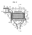
Fig. 2 is a cross-sectional view of the ignition coil taken along line A-A inFig. 1 . -
Fig. 3 is a cross-sectional view of the ignition coil taken along line B-B inFig. 2 . -
Fig. 4 is a perspective view showing the overview-shape of an iron core assembly according to the first embodiment. -
Fig. 5 is a perspective view of a core mold according to the first embodiment. -
Fig. 6 is a cross-sectional view of an ignition coil according to a second embodiment. -
Fig. 7 is a cross-sectional view of an ignition coil according to a third embodiment. -
Fig. 8 is a cross-sectional view of an ignition coil according to a fourth embodiment. -
Fig. 9 is a cross-sectional view of an ignition coil according to a fifth embodiment. -
Fig. 10 is a cross-sectional view of the ignition coil taken along line C-C inFigs. 2 and3 . -
Fig. 11 is an enlarged view of an upper-left portion ofFig. 3 . -
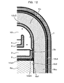
Fig. 12 is an enlarged view of an upper-right portion ofFig. 3 . -
Fig. 13 is an enlarged view of an upper-left portion ofFig. 6 . -
Fig. 14 is an enlarged view of a lower-right portion ofFig. 6 . - Preferred embodiments of the present invention will hereinafter be described with reference to the drawings.
- An ignition coil for an internal combustion engine according to a first embodiment of the present invention is shown in
Figs. 1 to 5 and10 to 12 .Fig. 1 is a top view of an ignition coil for an internal combustion engine according to the present embodiment.Fig. 2 is a cross-sectional view of the ignition coil taken along line A-A inFig. 1 .Fig. 3 is a cross-sectional view of the ignition coil taken along line B-B inFig. 2 .Fig. 4 is a perspective view showing an arrangement shape of iron cores.Fig. 5 is a perspective view showing the iron cores covered by elastic covers.Fig. 10 is a cross-sectional view of the ignition coil taken along line C-C inFigs. 2 and3 .Fig. 11 is an enlarged view of an upper-left portion ofFig. 3 .Fig. 12 is an enlarged view of an upper-right portion ofFig. 3 . - Referring to
Fig. 1 , an ignition coil 1 has acoil case 7 made of a resinous material. - The
coil case 7 is molded integrally with aconnector portion 8B and anattachment flange 1B. Theconnector portion 8B is used for connection with an external connector. - The
attachment flange 1B is used to attach the ignition coil 1 on a wall surface of an engine. Theattachment flange 1B is formed with ahole 1C adapted to receive an attachment screw inserted thereinto. A front surface of an insulatingresin 10 for insulating the inside of the coil case is seen on the upper surface of thecoil case 7. - Referring to
Figs. 2 and10 , the ignition coil 1 of the present embodiment is the so-called single ended ignition type ignition coil for an internal combustion engine. In the single ended ignition type, a plughole insertion portion 9A (described later) formed integrally with thecoil case 7 is inserted into a plug hole formed in each cylinder of the internal combustion engine. In addition, an output end of a secondary coil is directly connected to an ignition plug (not shown). - The ignition coil 1 according to the first embodiment has an iron core assembly 6 composed of a
main core portion 6a, aside core portion 6b and anauxiliary core portion 6c. Themain core portion 6a, theside core portion 6b and theauxiliary core portion 6c constitute a magnetic path indicated by an arrow Q inFig. 3 . - In the iron core assembly 6, the
main core portion 6a, theside core portion 6b and theauxiliary core portion 6c are each formed as a core portion by punching a silicon steel plate with a thickness of 0.2 to 0.7 mm into a respective shape, stacking a plurality of the silicon steel plates and press-forming the stacked silicon steel plates. - As shown in
Figs. 2 and10 , themain core portion 6a is inserted into the inside of aprimary coil bobbin 2 of rectangular cross-section. Theprimary coil bobbin 2 is formed of a thermoplastic synthetic resin. An enamel wire having a diameter of approximately 0.3 to 1.0 mm is wound around the outer circumference of theprimary coil bobbin 2 at several layers, several ten times per single layer, and approximately one hundred to three hundred times in total. - A
secondary coil bobbin 4 of rectangular cross-section is concentrically disposed around theprimary coil bobbin 2 with a clearance defined therebetween. Thesecondary coil bobbin 4 is formed of a thermoplastic synthetic resin similarly to theprimary coil bobbin 2. A plurality of winding grooves are formed on the outer circumference of thesecondary coil bobbin 4 in the longitudinal direction. An enamel wire having a diameter of approximately 0.03 to 0.1 mm is wound around the outer circumference of thesecondary coil bobbin 4 at several ten layers to several hundred layers per each groove, and five thousand to thirty thousand times in total. - The
primary coil bobbin 2 is inserted into the inside of thesecondary coil bobbin 4. Amagnet member 11 is mounted so as to be sandwiched between an auxiliary core portion side end of themain core portion 6a and theauxiliary core portion 6c. Themagnet member 11 is magnetized in the direction opposite to the direction of the magnetic flux generated in themain core portion 6a when theprimary coil 3 is energized. A primary coil portion C1, a secondary coil portion C2 and the iron core assembly 6 are housed in thecoil case 7. The primary coil portion C1 is composed of theprimary coil bobbin 2 and theprimary coil 3 wound around theprimary coil bobbin 2. The secondary coil portion C2 is composed of thesecondary coil bobbin 4 and thesecondary coil 5 wound around thesecondary coil bobbin 4. - The
coil case 7 is resin-molded integrally with aconnector portion 8B. Anelectric connection terminal 8A is insert-molded integrally with a resinous compact of thecoil case 7 in theconnector portion 8B. Theelectric connection terminal 8A is used to electrically connect theprimary coil 3 to the outside. A projectingportion 2C is formed at theauxiliary core portion 6c side end portion of theprimary coil bobbin 2 of theprimary coil 3 so as to extend to a stacking-directional upper surface of theauxiliary core portion 6c. Aninput terminal 8C is insert-molded in the projectingportion 2C. Theinput terminal 8C and theelectric connection terminal 8A of theconnector portion 8B are electrically interconnected inside thecoil case 7 via aline 8D. An electric current to be supplied to theprimary coil 3 is supplied thereto via theelectric connection terminal 8A. Although not shown, an external connector is inserted into theconnector portion 8B for connection and theelectric connection terminal 8A is connected to a power terminal of the external connector. - On the other hand, a high-
voltage terminal 9 is integrally insert-molded by a resin mold on a plughole insertion portion 9A side of thecoil case 7. Anoutput end 5A of a winding of thesecondary coil 5 is connected to the high-voltage terminal 9. An electric current applied to theprimary coil 3 is cut by a semiconductor switching element not shown to induce high voltage in thesecondary coil 5. The high voltage induced in thesecondary coil 5 is supplied to an ignition plug (not shown) via the high-voltage terminal 9 resin-molded integrally with thecoil case 7. Thus, the ignition plug generates spark discharge. - The
output terminal 5A of the winding of thesecondary coil 5 is connected to the high-voltage terminal 9 and theinput terminal 8C of the winding of the primary coil is connected to theelectric connection terminal 8A of theconnector portion 8B. In this state, the iron core assembly 6, the primary coil portion C1 and secondary coil portion C2 are housed and set up in thecoil case 7. A thermo-setting resin (specifically, an epoxy resin) as an insulatingresin 10 is filled in thecoil case 7. The insulatingresin 10 is filled in the entire inside of the coil case 7: clearances between the windings of theprimary coil 3 wound around theprimary coil bobbin 2 and between the windings of thesecondary coil 5 wound around thesecondary coil bobbin 4; the circumferences of the primary coil portion C1, the secondary coil portion C2 and the iron core assembly 6 and the clearances therebetween; the circumference of the connecting portion between theinput end 8C of theprimary coil 3 and the connecting terminal 8A of theconnector portion 8B; and the circumference of the connecting portion between the high-pressure terminal 9 and theoutput end 5A of thesecondary coil 5. In this way, these components are insulated from one another and united with one another in thecoil case 7. - As shown in
Figs. 3 and4 , the iron core assembly 6 of the present embodiment is composed of the three divided portions: themain core portion 6a, theside core portion 6b, and theauxiliary core portion 6c. Themagnet member 11 is shaped like a thin plate and assembled between themain core portion 6a and theauxiliary core portion 6c. Further, as shown inFig. 5 , the iron core assembly 6 and themagnet member 11 are covered on their outer surfaces by a mold material except joint surfaces 6a1, 6b2 between themain core portion 6a and theside core portion 6b, a joint surface 6c2 between themagnet member 11 and theauxiliary core portion 6c, joint surfaces 6c1, 6b1 between theside core portion 6b and theauxiliary core portion 6c, and a joint surface 6a2 between themagnet member 11 and themain core portion 6a. These covering layers are hereinafter called thecore molds core molds - In the present embodiment, the
non-magnetized magnet member 11 is sandwiched between flange portions 6a3 formed at end portions of themain core portion 6a and theauxiliary core portion 6c and is set up in a mold. A mold material (a thermoplastic resin, elastomer or rubber such as silicon rubber) is poured into the mold to cover the circumferential surfaces of themain core portion 6a, themagnet member 11 and theauxiliary core portion 6c. In this way, these three components are configured as a single molded assembly component. - In this case, the
main core portion 6a, themagnet member 11 and theauxiliary core portion 6c are tightly pressed so as to prevent the mold material from pouring in the joint surface between the main core portion and themagnet member 11 and the joint surface between themagnet member 11 and theauxiliary core portion 6c. The joint surface (both sides) 6c1 of theauxiliary core portion 6c with theside core portion 6b and the contact surface 6a1 of themain core portion 6a with theside core portion 6b are brought into tight contact with the front surface of the mold so as to prevent the molding material from extending over the joint surface and the contact surface mentioned above. Then, themain core portion 6a and theauxiliary core portion 6c are molded. A tape capable of being removed later may be applied to the joint surface (both sides) 6c1 of theauxiliary core portion 6c with theside core portion 6b and to the contact surface 6a1 of themain core portion 6a with theside core portion 6b. Then, themain core portion 6a and theauxiliary core portion 6c are molded. After the molding, the tape may be removed to expose the joint surface and the contact surface. - As shown in
Fig. 5 , a plurality of recessedportions 121 are formed in the front surface of the core mold 12 as an elastic covering portion. Theserecess portions 121 are formed after temporary pins which held themain core portion 6a and themagnet member 11 in the mold have been removed. The recessedportions 121 are used as holes to confirm whether or not the core mold 12 contains a magnet therein and of which type the core mold 12 is. - With this configuration, the respective assembly positions of the
auxiliary core portion 6c, themagnet member 11 and themain core portion 6a are determined in the mold. Therefore, their positions will not be misaligned after the molding of such components. The circumferential surface of anoutside portion 11E of themagnet member 11 sandwiched between themain core portion 6a and theauxiliary core portion 6c is covered and protected by the film of a core mold 12a4. Therefore, an edge portion of themagnet member 11 is hard to be damaged by shocks during the assembly. Even if the edge portion of themagnet member 11 is damaged, then broken pieces of the permanent magnet will not fly apart. Therefore, the broken pieces of the magnet member will not drop in a production line. - As shown in
Figs. 2 and5 , thecore mold 12a has a covering layer 12a1 covering an upper end portion (the upper end portion inFig. 2 ), in a stacking direction, of theauxiliary core portion 6c and a covering layer 12a2 covering a lower end portion (the lower end portion inFig. 2 ), in the stacking direction, of theauxiliary core portion 6c. The covering layers 12a1, 12a2 are formed thicker than the other portions of thecore mold 12a. The covering layer 12a1 formed thick faces the projectingportion 2C formed at an end portion of theprimary coil bobbin 2 of theprimary coil 3. The covering layer 12a2 covering the lower end surface (the lower end portion inFig. 2 ) of theauxiliary core portion 6c faces an end portion excluding the projectingportion 2C formed at the end portion of theprimary coil bobbin 2 of theprimary coil 3. - Further, the
core mold 12a has a covering layer 12a5 covering an longitudinal outer surface of themain core portion 6a, a covering layer 12a3 covering an outer surface portion of the flange portion 6a3, and a covering layer 12a4 covering the circumference of theouter side surface 11E of themagnet member 11. Theprimary coil bobbin 2 is inserted through above the covering layer of the core mold 12a5 of themain core portion 6a. Therefore, theprimary coil bobbin 2 is not rubbed by the edge of themain core portion 6a so that it will not chip off. - With this configuration, although the
magnet member 11 is assembled in the non-magnetized state, themain core portion 6a, themagnet member 11 and theauxiliary core portion 6c are positioned by being set up in the mold. Therefore, an assembly error for each product is small. After the molding, themain core portion 6a, themagnet member 11 and theauxiliary core portion 6c can be handled as one component; therefore, assembly performance is enhanced. This configuration is particularly advantageous to automated assembly. Incidentally, if thecore mold 12a is applied in the non-magnetized state, then magnetization is performed in a subsequent process. - As shown in
Figs. 2 ,3 and12 , similarly also theside core portion 6b is covered by the core mold 12 in the present embodiment. In this case, the contact surface 6b2 of theside core portion 6b with themain core portion 6a and the joint surface portion (both sides) of theside core portion 6b with theauxiliary core portion 6c are brought to tight contact with the mold to prevent the mold-covering member from pouring thereinto. Otherwise, a tape is applied to the contact surface and the joint surface portion and is removed therefrom to expose the contact surface and the joint surface portion. - In this way, the joint surfaces 6a1, 6b2 between the
main core portion 6a and theside core portion 6b and the joint surface portions 6b1, 6c1 between theside core portion 6b (both sides) and theside core portion 6c are in magnetically tight contact with each other to form an appropriate magnetic path. - As shown in
Figs. 3 ,11 and12 , theside core portion 6b has a linking core portion 6bc which is disposed parallel to theauxiliary core portion 6c with themain core portion 6a put therebetween. Theside core portion 6b has a pair of parallel core portions 6bs at both end portions of the linking core portion 6bc. The parallel core portions 6bs extend to theauxiliary core portion 6c in parallel to themain core portion 6a. The parallel core portions 6bs have leading end portions on both sides mating-engaged with corresponding end portions, on both sides, of theauxiliary core portion 6c at corresponding engaging portions 6bc. Specifically, projecting portions 6b2 formed at the leading end portions, on both sides, of the parallel core portions 6bs are brought into contact with the outside of corresponding end projecting portions 6c2 of theauxiliary core portion 6c. In addition, theauxiliary core portion 6c and theside core portion 6b are pressed to each other along themain core portion 6a. The projecting portion 6b2 is mating-engaged, in a pressure-contact state, with the projecting portion 6c2 of theauxiliary core portion 6c along the engaging surface 6c1 of theauxiliary core portion 6c. Similarly, the projecting portion 6c2 of theauxiliary core portion 6c is mating-engaged, in the pressure-contact state, with the projecting portion 6b2 along the inner engaging surface 6b1 of the end portion of the parallel core portion 6bs of theside core portion 6b. The projecting portions 6b2, 6c2 are fitted to each other in a state where the projecting portion 6b2 is expanded outwardly until the middle of the mating. In addition, the projecting portions 6b2, 6c2 are mating-engaged with each other at the engaging surface 6bc in a state where the projecting portion 6b2 is contracted inwardly when the projecting portion 6b2 overrides the engaging surface 6bc. The inner engaging surface 6b1 of the end portion of the parallel core portion 6bs of theside core portion 6b and the outer engaging surface 6c1 of theauxiliary core portion 6c are engaged with each other in an elastic state; therefore, they are brought into tight contact with each other with the engaging surface 6bc therebetween. In this case, the end portion 6a1 of themain core portion 6a is pressed against an exposed surface 6b2 of theside core portion 6b by elastic force occurring between the inner engaging surface 6b1 of the leading end portion of the parallel core portion 6bs of theside core portion 6b and the outer engaging surface 6c1 of theauxiliary core portion 6c. In this way, both themain core portion 6a and theside core portion 6b are brought into tight contact with each other at this portion. Thus, an appropriate magnetic path having small magnetic resistance is formed. - The configuration described above is useful to firmly hold the mutual positional relationship among the iron core assembly 6 and the coil portions C1, C2 until they are set up in the
coil case 7 and the molding is finished. - The
core mold 12b covering the circumference of theside core portion 6b has a covering layer 12b1 covering an upper end portion (the upper end portion inFig. 2 ), in a stacking direction, of theside core portion 6b and a covering layer 12b2 covering a lower end portion (the lower end portion inFig. 2 ), in the stacking direction, of theauxiliary core portion 6b. The covering layers 12b1, 12b2 are formed thicker than the other portions of thecore mold 12b. The covering layers 12b1, 12b2 formed thick face acylindrical end portion 2D formed at aside core portion 6b side end portion of theprimary coil bobbin 2 of theprimary coil 3. - As shown in
Fig. 3 , theprimary coil bobbin 2 of theprimary coil 3 hasflange portions portion 2C and thecylindrical end portion 2D. Theflange portion 2a has an end portion facing the covering layer 12a3 covering the inside of the flange portion 6a3 of themain core portion 6a. Theflange portion 2b has an end portion facing the covering layer 12b3 covering the inside of theside core portion 6b, particularly, facing the core mold 12b5 formed thin around the joint surface portion 6b2 between the end portion 6a1 of themain core portion 6a and theside core portion 6b. Clearances between both end portions of theprimary coil bobbin 2 and the covering layers 12a1, 12a2, 12a3 and 12b1, 12b2, 12b5 facing both the end portions thereof are set at 0 to 0.2 mm (millimeter) in the state where theauxiliary core portion 6c and theside core portion 6b are mating-engaged with each other. - Incidentally, the primary and secondary coil portions C1, C2 are temporarily mounted by engaging means not shown so as not to be relatively displaced in the longitudinal direction. Therefore, if the
side core portion 6b and theauxiliary core portion 6c are mating-engaged with each other in the state where the primary and secondary coil portions C1, C2 are attached to themain core portion 6a, theprimary coil bobbin 2 is held between theside core portion 6b and theauxiliary core portion 6c mostly without play. - The primary and secondary coil portions C1, C2, along with the iron core assembly 6, are set up in the
coil case 7 and the insulatingresin 10 is poured into the coil case. - In this case, the flow of the insulating
resin 10 reaches the clearance of 0 to 0.2 mm (millimeter) between both the end portions of theprimary coil bobbin 2 and the core molds 12a1, 12a2, 12a3; 12b1, 12b2, 12b5 facing both the end portions of theprimary bobbin 2. However, the clearance is originally small; therefore, theprimary coil bobbin 2 is not relatively displaced by the flow-pressure of the insulating resin. Theprimary coil bobbin 2 has both end faces firmly held between the core molds 12a1, 12a2, 12a3 and 12b1, 12b2, 12b5. Therefore, the winding is not disconnected and the joint portion between the winding and the connecting terminal does not come off. The molding resin becomes hardened which flows into the clearances of 0 to 0.2 mm (millimeter) between both the end faces of theprimary coil bobbin 2 and the core molds 12a1, 12a2, 12a3 and 12b1, 12b2, 12b5. Molding strain occurring due to this hardening is absorbed by thecore molds primary coil bobbin 2 and will not break themagnet member 11. - As described above, the
core molds core molds resin 10 covering the circumference of the core mold 12, as below. When the ignition coil 1 undergoes heat stress, the insulatingresin 10 may be subjected to stress concentration by the corner of the iron core and cracked. Specifically, if the corner portion of the core mold 12 is rounded, the insulatingresin 10 is hard to be cracked. However, the rounded portion having a larger radius is more effective. If the rounded portion is increased in radius, since the inner wall of the coil case is located in the outer circumferential direction of the iron core assembly, the core mold 12 is formed thick at the upper surface portion and lower surface portion, in the stacking direction, of the iron core assembly 6. If the core mold 12 is formed thick at a portion corresponding to the direction perpendicular to the stacking direction of the iron cores, i.e., to thecoil case 7 side, the ignition coil 1 grows in size. Because of this, the core mold 12 is formed thick in the stacking direction of iron cores; therefore, the corner portion of the core mold 12 can be made to have a large radius without the enlargement of the size of the ignition coil 1. Since the core mold 12 is provided with the thick portions, the flowing performance of resin is enhanced during the molding. Specifically, as shown inFigs. 2 ,5 and11 , the thick portions 12a1, 12a2 of the core mold is formed at the upper and lower end faces, in the stacking direction, of theauxiliary core portion 6c. As shown inFigs. 3 ,5 and12 , the thick portions 12b1, 12b2 of thecore mold 12b is formed at the upper and lower end faces of theside core portion 6b. - As shown in
Figs. 2 ,5 and11 , the core mold 12a5, the core mold 12a3 and a core mold 12a7 are each formed to have a thickness approximately 1/3 to 1/2 of the core mold 12a6 at the inside portion of both end portions of theauxiliary core portion 6c of theprimary coil bobbin 2. Incidentally, the core mold 12a5 is located at a surface portion of themain core portion 6a through which theprimary coil bobbin 2 is passed through. The core mold 12a3 is formed at the surface portion of the flange portion 6a3 of themain core portion 6a facing theflange portion 2a located at the end portion of theprimary coil bobbin 2. The core mold 12a7 is located at an external side surface portion of theauxiliary core portion 6c. Also a portion, close to themain core portion 6a, of the upper surface portion of theauxiliary core portion 6c is formed thin similarly to the core mold 12a5 at the surface portion of themain core portion 6a through which theprimary coil bobbin 2 is passed. - The iron core assembly 6 has a complicated shape and many edge portions on the inner circumferential surface side thereof. This inner circumferential surface side has enlarged clearances serving as mold-material flow passages formed between the iron core assembly 6 and the mold. This makes it easy for the mold material to flow. Consequently, the covering layers of the mold material are thick at large clearances (see the core molds 12a4, 12a6, 12b3).
- As shown in
Fig. 2 and5 , the core molds 12a1 and 12a5 of thecore mold 12a formed on the upper surface side, in the stacking direction inFig. 2 , of the iron core assembly 6 are formed thick and thin, respectively. Therefore, thecore mold 12a is formed in a concavo-convex shape in which the inside is concave and the outside is convex. The concavo-convex portion of thecore mold 12a is formed to surround the circumference of the projectingportion 2C, of theprimary coil bobbin 2, formed at theauxiliary core portion 6c side end. In addition, the concavo-convex portion of thecore mold 12a serves to position theprimary coil bobbin 2 at the time of assembling it to the outer circumference of the iron core assembly 6. On the lower end surface side of theauxiliary core portion 6c, the thick portion of thecore mold 12a extends to under the magnet member. In addition, the thin portion of thecore mold 12a extends from the joint surface between thecore mold 12a and themagnet member 11 to theside core portion 6b side end portion of the main core portion 12. As described above, thecore mold 12a is made different in thickness and shape between the upper surface and the lower surface; therefore, it is possible to prevent the core mold 12 from being assembled in an erroneous direction, i.e., to prevent the so-called erroneous assembly. - A second embodiment is hereinafter described with reference to
Figs. 6 ,13 and14 . - In the second embodiment, a
main core portion 6a and anauxiliary core portion 6c are punched out as an integral thin steel plate and the integral thin plates are stacked one on another. Therefore, a magnet member is not installed between themain core portion 6a and theauxiliary core portion 6c. - The
coil case 7 is shared by the first embodiment and the second embodiment; therefore, an iron core assembly 6 has the same external dimensions as those of the first embodiment. The second embodiment uses the same coil assembly as that of the first embodiment. - A core mold 12a8 between an end portion of a
primary coil bobbin 2 and theauxiliary core portion 6c is increased in thickness by the thickness of themagnet member 11. In addition, the core mold 12a8 has an outer shape formed to conform to the shape of a projecting portion of theprimary coil bobbin 2. - The
main core portion 6a has aside core portion 6b side end portion covered by a core mold 12a9. Consequently, a magnetic gap corresponding to the thickness of the core mold 12a9 is defined between theside core portion 6b and the end portion of themain core portion 6a. Thus, magnetic saturation of a magnetic path is suppressed at this portion. - In this way, the auxiliary core portion and main core portion covered by the core molds 12a7, 12a8, 12a3, 12a9 according to the second embodiment are formed to have the same external shape as that according to the first embodiment.
- Thus, the auxiliary core portion and the main core portion can be handled as one component during assembly regardless of the absence or presence of the magnet member. As described above, the auxiliary core portion and the main core portion are covered by the core molds; therefore, ignition coils can be assembled in the same production line regardless of the absence or presence of the magnet member. This leads to the reduced cost of installation.
- Incidentally, to prevent erroneous assembly in the same production line by distinguishing between the absence and presence of the magnet assembly, it is preferable to make it possible to visually confirm the absence and presence of the magnet member by forming a concavo-convex portion on the core mold on the iron-core-stacking-directional surfaces as shown in
Fig. 5 . - As shown in
Fig. 7 , an ignition coil according to a third embodiment is configured to have only one side of theside core portion 6b in the first embodiment. In this case, a fitting-recessed portion 6cb is located on a lateral surface of anauxiliary core portion 6c. In addition, a fitting-projection 6bc is located at an end portion of theside core portion 6b corresponding to the fitting-recessed portion 6cb. A fitting-recessed portion 6ab is located on an end lateral surface, of themain core portion 6a, on the side opposite the auxiliary core portion side. In addition, a fitting-projection 6ba is located at an end portion of theside core portion 6b corresponding to the fitting-recessed portion 6ab. The fitting-recessed portion 6cb is fitted to the fitting projection 6bc. The fitting-recessed portion 6ab is fitted to the fitting projection 6ba. Thus, an iron core assembly can be formed. - A fourth embodiment is described with reference to
Fig. 8 . Referring toFig. 8 , theauxiliary core portion 6c and themain core portion 6a in the second embodiment are each divided into twoparts main core portion 6a. In addition, theside core portion 6b inFig. 8 is divided into twoparts - Referring to
Fig. 9 , in a fifth embodiment, anauxiliary core portion 6c and amain core portion 6a are punched out as steel plates divided similarly to the first embodiment. The steel plates of theauxiliary core portion 6c and those of themain core portions 6a are separately stacked and united together. Thereafter, both are covered by a core mold 12 without a magnet member. - In the embodiments described above, the material of the iron core assembly 6 is the stacked silicon steel plates. However, also iron cores formed by compressing iron-based powder and covered by a resinous cover, an elastomer film or a rubber film can produce the same function and effect as above.
- Features, components and specific details of the structures of the above-described embodiments may be exchanged or combined to form further embodiments optimized for the respective application. As far as those modifications are apparent for an expert skilled in the art they shall be disclosed implicitly by the above description without specifying explicitly every possible combination.
-
- [1]. An ignition coil comprising:
- a coil;
- a main core portion to which the coil is attached;
- a side core portion surrounding the circumference of the coil;
- an auxiliary core portion connecting the main core portion with the side core portion; and
- a permanent magnet disposed between the auxiliary core portion and the main core portion;
the permanent magnet generating magnetic flux in a direction opposite to magnetic flux passing through the closed magnetic path,
a resin film or an elastic film covers the circumference of the side core portion except a joint surface of the side core portion to the auxiliary core portion and a joint surface of the side core portion to the main core portion, and
in a state where the auxiliary core portion and the main core portion are combined with each other with the permanent magnet sandwiched therebetween, a resin film or an elastic film covers respective circumferences of the auxiliary core portion, the permanent magnet, and the main core portion except a joint surface of the auxiliary core portion to the side core portion and a joint surface of the main core portion to the side core portion. - [2]. An ignition coil comprising:
- a coil;
- a main core portion to which the coil is attached;
- a side core portion surrounding the circumference of the coil; and
- an auxiliary core portion connecting the main core portion with the side core portion;
a resin film or an elastic film covers the circumference of the side core portion except a joint surface of the side core portion to the auxiliary core portion and a joint surface of the side core portion to the main core portion, and
in a state where the auxiliary core portion and the main core portion are combined with each other, the resin film or the elastic film covers respective circumferences of the auxiliary core portion and the main core portion except a joint surface of the auxiliary core portion to the side core portion and a joint surface of main core portion to the side core portion. - [3]. The ignition coil according to [1] or [2], wherein the resin film or elastic film covering the core portions has a thickness greater in an iron core stacking direction than in a direction perpendicular to the iron core stacking direction.
- [4]. The ignition coil according to [1] or [2], wherein the resin film or the elastic film covering both surfaces, in the iron core stacking direction, of the core portions is partially formed with a recessed portion reaching surfaces of the core portions or the permanent magnet.
- [5]. The ignition coil according to [1] or [2], wherein a primary coil portion is attached to an outer circumference of the resin film or the elastic film at a portion corresponding to the main core portion of an assembly of the main core portion and the auxiliary core portion, a secondary coil portion is attached to an outer circumference of the primary coil portion, the assembly of the main core portion and the auxiliary core portion, the primary coil portion, the secondary coil portion and the side core portion are housed in a coil case, and an insulating resin is filled in the coil case and the coil case is sealed.
- [6]. The ignition coil according to [1] or [2], wherein a division surface of the core portion is formed as a surface perpendicular to an iron core stacking direction.
- [7]. The ignition coil according to [1] or [2], wherein the resin film or the elastic film covering the outer circumference of the core portion is provided with convexity and concavity on one side or both sides, in an iron core stacking direction, of the auxiliary core portion and of the side core portion, and when a bobbin around which the coil is wound is attached to the outer circumference of the main core portion, the bobbin is positioned.
- [8]. The ignition coil according to [1],
wherein an engaging portion is formed between a side surface of the auxiliary core portion and one end portion of the side core portion and between an end portion side surface, of the main core portion, on a side opposite to the auxiliary core portion and the other end portion of the side core portion. - [9]. The ignition coil according to [1],
wherein the main core portion is divided into parts in a longitudinal direction, and in a state where the divided parts of the main core portion are joined together, the resin film or the elastic film covers the circumference of the main core portion except a joint surface of the main core portion to the side core portion. - [10]. The ignition coil according to [1],
wherein the side core portion is divided into parts symmetrically with respect to a longitudinal axis of the main core portion, and in a state where the divided parts of the side core portion are joined together, the resin film or the elastic film covers the circumference of the side core portion except a joint surface of the side core portion to the main core portion.
Claims (9)
- An ignition coil comprising:a coil being attached to a main core portion (6a), and being sandwiched between and held by an auxiliary core portion (6c)and a side core portion (6b); anda covering layer made of an elastic body, the covering layer being formed in a clearance at least between an end face of a coil bobbin and an inner circumferential surface of the main core portion (6a) or the auxiliary core portion (6c) facing the end face of the coil bobbin.
- The ignition coil according to claim 1,
wherein the covering layer is formed over the full circumferences of the main core portion (6a) and the auxiliary core portion (6c) except a fitting-engaging portion of the auxiliary core portion (6c) with the side core portion (6b). - The ignition coil according to claim 1,
wherein the covering layer is also formed on an inner circumferential surface, of the side core portion (6b), facing the coil bobbin. - The ignition coil according to claim 1,
wherein inner and outer full circumferences of an iron core assembly are covered by the covering layer except an fitting-engaging portion of the auxiliary core portion (6c) with the side core portion (6b) and a contact surface portion between the main core portion (6a) and the side core portion (6b). - The ignition coil according to claim 1,
wherein a magnet member (11) is sandwiched between the auxiliary core portion (6c) and the main core portion (6a). - The ignition coil according to claim 5,
wherein the magnet member (11) is a magnetized magnet member. - The ignition coil according to claim 5,
wherein the magnet member (11) is a non-magnetized magnet member. - The ignition coil according to claim 1,
wherein the auxiliary core portion (6c) and the main core portion (6a) are formed as a continuous integral one by punching out a steel plate and stacking the steel plates. - The ignition coil according to claim 1,
wherein a fitting-engaging portion of the auxiliary core portion (6c) with the side core portion (6b) is formed between an end portion outer circumferential surface of the auxiliary core portion (6c) and an end portion inner circumferential surface of the side core portion (6b) or between an end portion inner circumferential surface of the auxiliary core portion (6c) and an end portion outer circumferential surface of the side core portion (6b).
Applications Claiming Priority (1)
| Application Number | Priority Date | Filing Date | Title |
|---|---|---|---|
| JP2011118609A JP5478555B2 (en) | 2011-05-27 | 2011-05-27 | Ignition coil for internal combustion engine |
Publications (4)
| Publication Number | Publication Date |
|---|---|
| EP2528074A2 true EP2528074A2 (en) | 2012-11-28 |
| EP2528074A3 EP2528074A3 (en) | 2017-11-29 |
| EP2528074B1 EP2528074B1 (en) | 2021-08-25 |
| EP2528074B8 EP2528074B8 (en) | 2021-09-29 |
Family
ID=46419877
Family Applications (1)
| Application Number | Title | Priority Date | Filing Date |
|---|---|---|---|
| EP12169188.5A Active EP2528074B8 (en) | 2011-05-27 | 2012-05-24 | Ignition coil for internal combustion engine |
Country Status (4)
| Country | Link |
|---|---|
| US (1) | US8922314B2 (en) |
| EP (1) | EP2528074B8 (en) |
| JP (1) | JP5478555B2 (en) |
| CN (1) | CN102800470B (en) |
Families Citing this family (27)
| Publication number | Priority date | Publication date | Assignee | Title |
|---|---|---|---|---|
| JP5677247B2 (en) * | 2011-09-20 | 2015-02-25 | 日立オートモティブシステムズ株式会社 | Ignition coil for internal combustion engine |
| JP5919997B2 (en) * | 2012-04-26 | 2016-05-18 | 株式会社デンソー | Ignition coil for internal combustion engine |
| US9117585B2 (en) | 2013-07-16 | 2015-08-25 | Delphi Technologies, Inc. | Ignition coil |
| JP6383202B2 (en) * | 2014-07-24 | 2018-08-29 | 株式会社三井ハイテック | Manufacturing method of laminated iron core and laminated iron core |
| JP6428059B2 (en) * | 2014-08-29 | 2018-11-28 | 株式会社デンソー | Ignition coil for internal combustion engine |
| JP6350143B2 (en) * | 2014-09-08 | 2018-07-04 | 株式会社デンソー | Ignition coil for internal combustion engines |
| JP6409484B2 (en) * | 2014-10-10 | 2018-10-24 | 株式会社デンソー | Ignition coil for internal combustion engine |
| CN107430932B (en) * | 2015-04-15 | 2020-06-16 | 三菱电机株式会社 | Ignition coil for internal combustion engine |
| US10090099B2 (en) * | 2015-06-09 | 2018-10-02 | Delphi Technologies Ip Limited | Spark ignition transformer with a non-linear secondary current characteristic |
| JP6416045B2 (en) * | 2015-06-18 | 2018-10-31 | 日立オートモティブシステムズ阪神株式会社 | Ignition coil for internal combustion engine |
| JP6448010B2 (en) * | 2015-07-09 | 2019-01-09 | 日立オートモティブシステムズ阪神株式会社 | Ignition device for internal combustion engine |
| JP6468143B2 (en) * | 2015-09-16 | 2019-02-13 | 株式会社デンソー | Ignition coil for internal combustion engines |
| JP6613166B2 (en) * | 2016-02-19 | 2019-11-27 | 日立オートモティブシステムズ阪神株式会社 | Ignition coil for internal combustion engine and method for manufacturing ignition coil for internal combustion engine |
| CN108701537B (en) | 2016-02-26 | 2020-12-08 | 三菱电机株式会社 | Ignition coil device for internal combustion engine |
| WO2017179118A1 (en) * | 2016-04-12 | 2017-10-19 | 三菱電機株式会社 | Internal combustion engine ignition device |
| JP6680058B2 (en) * | 2016-04-13 | 2020-04-15 | 株式会社デンソー | Ignition coil for internal combustion engine |
| KR101724119B1 (en) * | 2016-10-28 | 2017-04-07 | (주)현대산업 | Magnetic core for automotive ignition coils and a method of manufacturing the same |
| CN109637775B (en) * | 2017-10-06 | 2023-11-07 | 株式会社电装 | Ignition coil for internal combustion engine |
| JP7099204B2 (en) * | 2017-10-06 | 2022-07-12 | 株式会社デンソー | Ignition coil for internal combustion engine |
| DE112017008285T5 (en) * | 2017-12-19 | 2020-08-27 | Mitsubishi Electric Corporation | Ignition coil device for internal combustion engine |
| JP7091215B2 (en) * | 2018-10-01 | 2022-06-27 | 日立Astemo阪神株式会社 | Ignition coil for internal combustion engine |
| US11551861B2 (en) * | 2018-10-25 | 2023-01-10 | Mitsubishi Electric Corporation | Ignition coil |
| DE102018130492B4 (en) * | 2018-11-30 | 2023-02-09 | Borgwarner Ludwigsburg Gmbh | ignition coil |
| JP7275825B2 (en) * | 2019-05-10 | 2023-05-18 | 株式会社デンソー | Ignition coil for internal combustion engine |
| JP7456096B2 (en) * | 2019-06-11 | 2024-03-27 | 株式会社デンソー | ignition coil |
| JP7358839B2 (en) * | 2019-08-22 | 2023-10-11 | 株式会社デンソー | ignition coil |
| JP7359015B2 (en) | 2020-02-10 | 2023-10-11 | 株式会社デンソー | ignition coil |
Citations (2)
| Publication number | Priority date | Publication date | Assignee | Title |
|---|---|---|---|---|
| JPH0817657A (en) | 1994-06-24 | 1996-01-19 | Nippondenso Co Ltd | Closed magnetic path iron core molten ignition coil |
| JP2007194364A (en) | 2006-01-18 | 2007-08-02 | Hitachi Ltd | Ignition coil for internal combustion engine |
Family Cites Families (13)
| Publication number | Priority date | Publication date | Assignee | Title |
|---|---|---|---|---|
| JPS5930501Y2 (en) * | 1980-08-29 | 1984-08-31 | 株式会社デンソー | Integrated core molded ignition coil |
| ES2040409T3 (en) * | 1988-07-28 | 1993-10-16 | Nippondenso Co., Ltd. | IGNITION COIL. |
| JPH0256910A (en) * | 1988-08-22 | 1990-02-26 | Nippon Denso Co Ltd | Core of ignition coil |
| US5225801A (en) * | 1990-04-28 | 1993-07-06 | Toyo Denso Kabushiki Kaisha | Ignition coil device for engine |
| JPH0845755A (en) * | 1994-08-02 | 1996-02-16 | Aisan Ind Co Ltd | Ignition coil for internal combustion engine |
| JP3228840B2 (en) * | 1994-10-07 | 2001-11-12 | 三菱電機株式会社 | Ignition coil device for internal combustion engine and method of manufacturing the same |
| JPH10199737A (en) * | 1996-11-18 | 1998-07-31 | Matsushita Electric Ind Co Ltd | Ignition coil device for internal combustion engine |
| JP3610054B2 (en) * | 2002-06-13 | 2005-01-12 | 三菱電機株式会社 | Ignition device for internal combustion engine |
| JP2006278379A (en) * | 2005-03-28 | 2006-10-12 | Hanshin Electric Co Ltd | Ignition coil for internal combustion engine |
| JP4209403B2 (en) * | 2005-04-12 | 2009-01-14 | 三菱電機株式会社 | Ignition device for internal combustion engine |
| JP4187005B2 (en) * | 2006-04-24 | 2008-11-26 | 国産電機株式会社 | Ignition coil and ignition device for internal combustion engine |
| JP2011066098A (en) * | 2009-09-16 | 2011-03-31 | Hitachi Automotive Systems Ltd | Transformer |
| US8289117B2 (en) * | 2010-06-15 | 2012-10-16 | Federal-Mogul Corporation | Ignition coil with energy storage and transformation |
-
2011
- 2011-05-27 JP JP2011118609A patent/JP5478555B2/en active Active
-
2012
- 2012-05-21 CN CN201210158910.3A patent/CN102800470B/en active Active
- 2012-05-24 US US13/479,351 patent/US8922314B2/en active Active
- 2012-05-24 EP EP12169188.5A patent/EP2528074B8/en active Active
Patent Citations (2)
| Publication number | Priority date | Publication date | Assignee | Title |
|---|---|---|---|---|
| JPH0817657A (en) | 1994-06-24 | 1996-01-19 | Nippondenso Co Ltd | Closed magnetic path iron core molten ignition coil |
| JP2007194364A (en) | 2006-01-18 | 2007-08-02 | Hitachi Ltd | Ignition coil for internal combustion engine |
Also Published As
| Publication number | Publication date |
|---|---|
| US8922314B2 (en) | 2014-12-30 |
| EP2528074A3 (en) | 2017-11-29 |
| JP2012248645A (en) | 2012-12-13 |
| EP2528074B8 (en) | 2021-09-29 |
| JP5478555B2 (en) | 2014-04-23 |
| US20120299679A1 (en) | 2012-11-29 |
| EP2528074B1 (en) | 2021-08-25 |
| CN102800470A (en) | 2012-11-28 |
| CN102800470B (en) | 2015-09-02 |
Similar Documents
| Publication | Publication Date | Title |
|---|---|---|
| EP2528074B1 (en) | Ignition coil for internal combustion engine | |
| JP4209403B2 (en) | Ignition device for internal combustion engine | |
| JP5365305B2 (en) | Resin mold core and reactor | |
| JP5614501B2 (en) | Rotating electric machine rotor, rotating electric machine, and method for manufacturing rotating electric machine rotor | |
| JP5997111B2 (en) | Resin mold core and reactor using it | |
| JP5459173B2 (en) | Induction equipment | |
| JP2007027204A (en) | Ignition coil and its manufacturing method | |
| JP7133295B2 (en) | Reactor | |
| JP3453792B2 (en) | Ignition coil for internal combustion engine | |
| US11551861B2 (en) | Ignition coil | |
| TW201801447A (en) | Stator for dynamo-electrical machine | |
| CN107408451B (en) | Resin case for inductance element and inductance element | |
| JP5664283B2 (en) | Ignition coil for internal combustion engine and method of manufacturing the same | |
| JP5941717B2 (en) | Resin mold coil device | |
| JP7255153B2 (en) | Reactor and manufacturing method thereof | |
| JP2018133499A (en) | Reactor and manufacturing method thereof | |
| JP2017147775A (en) | Magnet insertion method | |
| JP5344158B2 (en) | Reactor, reactor bobbin, and converter | |
| JP5460533B2 (en) | Closed magnetic circuit type transformer | |
| US11776740B2 (en) | Spark coil with the lead terminal between flanges | |
| JP2022170059A (en) | Reactor and method for manufacturing reactor | |
| JP2021068830A (en) | Busbar assembly | |
| JP5071279B2 (en) | Ignition coil | |
| JP2011082469A (en) | Ignition coil | |
| JP2020161632A (en) | Ignition coil |
Legal Events
| Date | Code | Title | Description |
|---|---|---|---|
| PUAI | Public reference made under article 153(3) epc to a published international application that has entered the european phase |
Free format text: ORIGINAL CODE: 0009012 |
|
| 17P | Request for examination filed |
Effective date: 20120914 |
|
| AK | Designated contracting states |
Kind code of ref document: A2 Designated state(s): AL AT BE BG CH CY CZ DE DK EE ES FI FR GB GR HR HU IE IS IT LI LT LU LV MC MK MT NL NO PL PT RO RS SE SI SK SM TR |
|
| AX | Request for extension of the european patent |
Extension state: BA ME |
|
| PUAL | Search report despatched |
Free format text: ORIGINAL CODE: 0009013 |
|
| AK | Designated contracting states |
Kind code of ref document: A3 Designated state(s): AL AT BE BG CH CY CZ DE DK EE ES FI FR GB GR HR HU IE IS IT LI LT LU LV MC MK MT NL NO PL PT RO RS SE SI SK SM TR |
|
| AX | Request for extension of the european patent |
Extension state: BA ME |
|
| RIC1 | Information provided on ipc code assigned before grant |
Ipc: H01F 38/12 20060101AFI20171020BHEP |
|
| TPAC | Observations filed by third parties |
Free format text: ORIGINAL CODE: EPIDOSNTIPA |
|
| STAA | Information on the status of an ep patent application or granted ep patent |
Free format text: STATUS: EXAMINATION IS IN PROGRESS |
|
| 17Q | First examination report despatched |
Effective date: 20200212 |
|
| STAA | Information on the status of an ep patent application or granted ep patent |
Free format text: STATUS: EXAMINATION IS IN PROGRESS |
|
| GRAP | Despatch of communication of intention to grant a patent |
Free format text: ORIGINAL CODE: EPIDOSNIGR1 |
|
| STAA | Information on the status of an ep patent application or granted ep patent |
Free format text: STATUS: GRANT OF PATENT IS INTENDED |
|
| INTG | Intention to grant announced |
Effective date: 20210316 |
|
| RIN1 | Information on inventor provided before grant (corrected) |
Inventor name: TAKAHASHI, MAKIO Inventor name: ANZO, YOICHI Inventor name: KOBAYASHI, TAKANOBU |
|
| GRAS | Grant fee paid |
Free format text: ORIGINAL CODE: EPIDOSNIGR3 |
|
| GRAA | (expected) grant |
Free format text: ORIGINAL CODE: 0009210 |
|
| STAA | Information on the status of an ep patent application or granted ep patent |
Free format text: STATUS: THE PATENT HAS BEEN GRANTED |
|
| AK | Designated contracting states |
Kind code of ref document: B1 Designated state(s): AL AT BE BG CH CY CZ DE DK EE ES FI FR GB GR HR HU IE IS IT LI LT LU LV MC MK MT NL NO PL PT RO RS SE SI SK SM TR |
|
| REG | Reference to a national code |
Ref country code: GB Ref legal event code: FG4D |
|
| REG | Reference to a national code |
Ref country code: CH Ref legal event code: EP |
|
| REG | Reference to a national code |
Ref country code: DE Ref legal event code: R081 Ref document number: 602012076500 Country of ref document: DE Owner name: HITACHI ASTEMO, LTD., HITACHINAKA-SHI, JP Free format text: FORMER OWNER: HITACHI AUTOMOTIVE SYSTEMS, LTD., HITACHINAKA-SHI, IBARAKI, JP |
|
| REG | Reference to a national code |
Ref country code: AT Ref legal event code: REF Ref document number: 1424650 Country of ref document: AT Kind code of ref document: T Effective date: 20210915 Ref country code: CH Ref legal event code: PK Free format text: BERICHTIGUNG B8 Ref country code: IE Ref legal event code: FG4D |
|
| REG | Reference to a national code |
Ref country code: DE Ref legal event code: R096 Ref document number: 602012076500 Country of ref document: DE |
|
| RAP4 | Party data changed (patent owner data changed or rights of a patent transferred) |
Owner name: HITACHI ASTEMO, LTD. |
|
| REG | Reference to a national code |
Ref country code: LT Ref legal event code: MG9D |
|
| REG | Reference to a national code |
Ref country code: NL Ref legal event code: MP Effective date: 20210825 |
|
| REG | Reference to a national code |
Ref country code: AT Ref legal event code: MK05 Ref document number: 1424650 Country of ref document: AT Kind code of ref document: T Effective date: 20210825 |
|
| PG25 | Lapsed in a contracting state [announced via postgrant information from national office to epo] |
Ref country code: SE Free format text: LAPSE BECAUSE OF FAILURE TO SUBMIT A TRANSLATION OF THE DESCRIPTION OR TO PAY THE FEE WITHIN THE PRESCRIBED TIME-LIMIT Effective date: 20210825 Ref country code: HR Free format text: LAPSE BECAUSE OF FAILURE TO SUBMIT A TRANSLATION OF THE DESCRIPTION OR TO PAY THE FEE WITHIN THE PRESCRIBED TIME-LIMIT Effective date: 20210825 Ref country code: FI Free format text: LAPSE BECAUSE OF FAILURE TO SUBMIT A TRANSLATION OF THE DESCRIPTION OR TO PAY THE FEE WITHIN THE PRESCRIBED TIME-LIMIT Effective date: 20210825 Ref country code: ES Free format text: LAPSE BECAUSE OF FAILURE TO SUBMIT A TRANSLATION OF THE DESCRIPTION OR TO PAY THE FEE WITHIN THE PRESCRIBED TIME-LIMIT Effective date: 20210825 Ref country code: NO Free format text: LAPSE BECAUSE OF FAILURE TO SUBMIT A TRANSLATION OF THE DESCRIPTION OR TO PAY THE FEE WITHIN THE PRESCRIBED TIME-LIMIT Effective date: 20211125 Ref country code: PT Free format text: LAPSE BECAUSE OF FAILURE TO SUBMIT A TRANSLATION OF THE DESCRIPTION OR TO PAY THE FEE WITHIN THE PRESCRIBED TIME-LIMIT Effective date: 20211227 Ref country code: RS Free format text: LAPSE BECAUSE OF FAILURE TO SUBMIT A TRANSLATION OF THE DESCRIPTION OR TO PAY THE FEE WITHIN THE PRESCRIBED TIME-LIMIT Effective date: 20210825 Ref country code: LT Free format text: LAPSE BECAUSE OF FAILURE TO SUBMIT A TRANSLATION OF THE DESCRIPTION OR TO PAY THE FEE WITHIN THE PRESCRIBED TIME-LIMIT Effective date: 20210825 Ref country code: AT Free format text: LAPSE BECAUSE OF FAILURE TO SUBMIT A TRANSLATION OF THE DESCRIPTION OR TO PAY THE FEE WITHIN THE PRESCRIBED TIME-LIMIT Effective date: 20210825 Ref country code: BG Free format text: LAPSE BECAUSE OF FAILURE TO SUBMIT A TRANSLATION OF THE DESCRIPTION OR TO PAY THE FEE WITHIN THE PRESCRIBED TIME-LIMIT Effective date: 20211125 |
|
| PG25 | Lapsed in a contracting state [announced via postgrant information from national office to epo] |
Ref country code: PL Free format text: LAPSE BECAUSE OF FAILURE TO SUBMIT A TRANSLATION OF THE DESCRIPTION OR TO PAY THE FEE WITHIN THE PRESCRIBED TIME-LIMIT Effective date: 20210825 Ref country code: LV Free format text: LAPSE BECAUSE OF FAILURE TO SUBMIT A TRANSLATION OF THE DESCRIPTION OR TO PAY THE FEE WITHIN THE PRESCRIBED TIME-LIMIT Effective date: 20210825 Ref country code: GR Free format text: LAPSE BECAUSE OF FAILURE TO SUBMIT A TRANSLATION OF THE DESCRIPTION OR TO PAY THE FEE WITHIN THE PRESCRIBED TIME-LIMIT Effective date: 20211126 |
|
| PG25 | Lapsed in a contracting state [announced via postgrant information from national office to epo] |
Ref country code: NL Free format text: LAPSE BECAUSE OF FAILURE TO SUBMIT A TRANSLATION OF THE DESCRIPTION OR TO PAY THE FEE WITHIN THE PRESCRIBED TIME-LIMIT Effective date: 20210825 |
|
| PG25 | Lapsed in a contracting state [announced via postgrant information from national office to epo] |
Ref country code: DK Free format text: LAPSE BECAUSE OF FAILURE TO SUBMIT A TRANSLATION OF THE DESCRIPTION OR TO PAY THE FEE WITHIN THE PRESCRIBED TIME-LIMIT Effective date: 20210825 |
|
| REG | Reference to a national code |
Ref country code: DE Ref legal event code: R097 Ref document number: 602012076500 Country of ref document: DE |
|
| PG25 | Lapsed in a contracting state [announced via postgrant information from national office to epo] |
Ref country code: SM Free format text: LAPSE BECAUSE OF FAILURE TO SUBMIT A TRANSLATION OF THE DESCRIPTION OR TO PAY THE FEE WITHIN THE PRESCRIBED TIME-LIMIT Effective date: 20210825 Ref country code: SK Free format text: LAPSE BECAUSE OF FAILURE TO SUBMIT A TRANSLATION OF THE DESCRIPTION OR TO PAY THE FEE WITHIN THE PRESCRIBED TIME-LIMIT Effective date: 20210825 Ref country code: RO Free format text: LAPSE BECAUSE OF FAILURE TO SUBMIT A TRANSLATION OF THE DESCRIPTION OR TO PAY THE FEE WITHIN THE PRESCRIBED TIME-LIMIT Effective date: 20210825 Ref country code: EE Free format text: LAPSE BECAUSE OF FAILURE TO SUBMIT A TRANSLATION OF THE DESCRIPTION OR TO PAY THE FEE WITHIN THE PRESCRIBED TIME-LIMIT Effective date: 20210825 Ref country code: CZ Free format text: LAPSE BECAUSE OF FAILURE TO SUBMIT A TRANSLATION OF THE DESCRIPTION OR TO PAY THE FEE WITHIN THE PRESCRIBED TIME-LIMIT Effective date: 20210825 Ref country code: AL Free format text: LAPSE BECAUSE OF FAILURE TO SUBMIT A TRANSLATION OF THE DESCRIPTION OR TO PAY THE FEE WITHIN THE PRESCRIBED TIME-LIMIT Effective date: 20210825 |
|
| PLBE | No opposition filed within time limit |
Free format text: ORIGINAL CODE: 0009261 |
|
| STAA | Information on the status of an ep patent application or granted ep patent |
Free format text: STATUS: NO OPPOSITION FILED WITHIN TIME LIMIT |
|
| PG25 | Lapsed in a contracting state [announced via postgrant information from national office to epo] |
Ref country code: IT Free format text: LAPSE BECAUSE OF FAILURE TO SUBMIT A TRANSLATION OF THE DESCRIPTION OR TO PAY THE FEE WITHIN THE PRESCRIBED TIME-LIMIT Effective date: 20210825 |
|
| 26N | No opposition filed |
Effective date: 20220527 |
|
| PG25 | Lapsed in a contracting state [announced via postgrant information from national office to epo] |
Ref country code: SI Free format text: LAPSE BECAUSE OF FAILURE TO SUBMIT A TRANSLATION OF THE DESCRIPTION OR TO PAY THE FEE WITHIN THE PRESCRIBED TIME-LIMIT Effective date: 20210825 |
|
| REG | Reference to a national code |
Ref country code: CH Ref legal event code: PL |
|
| REG | Reference to a national code |
Ref country code: BE Ref legal event code: MM Effective date: 20220531 |
|
| GBPC | Gb: european patent ceased through non-payment of renewal fee |
Effective date: 20220524 |
|
| PG25 | Lapsed in a contracting state [announced via postgrant information from national office to epo] |
Ref country code: MC Free format text: LAPSE BECAUSE OF FAILURE TO SUBMIT A TRANSLATION OF THE DESCRIPTION OR TO PAY THE FEE WITHIN THE PRESCRIBED TIME-LIMIT Effective date: 20210825 Ref country code: LU Free format text: LAPSE BECAUSE OF NON-PAYMENT OF DUE FEES Effective date: 20220524 Ref country code: LI Free format text: LAPSE BECAUSE OF NON-PAYMENT OF DUE FEES Effective date: 20220531 Ref country code: CH Free format text: LAPSE BECAUSE OF NON-PAYMENT OF DUE FEES Effective date: 20220531 |
|
| PG25 | Lapsed in a contracting state [announced via postgrant information from national office to epo] |
Ref country code: IE Free format text: LAPSE BECAUSE OF NON-PAYMENT OF DUE FEES Effective date: 20220524 Ref country code: FR Free format text: LAPSE BECAUSE OF NON-PAYMENT OF DUE FEES Effective date: 20220531 |
|
| PG25 | Lapsed in a contracting state [announced via postgrant information from national office to epo] |
Ref country code: GB Free format text: LAPSE BECAUSE OF NON-PAYMENT OF DUE FEES Effective date: 20220524 Ref country code: BE Free format text: LAPSE BECAUSE OF NON-PAYMENT OF DUE FEES Effective date: 20220531 |
|
| PGFP | Annual fee paid to national office [announced via postgrant information from national office to epo] |
Ref country code: DE Payment date: 20230331 Year of fee payment: 12 |
|
| PG25 | Lapsed in a contracting state [announced via postgrant information from national office to epo] |
Ref country code: HU Free format text: LAPSE BECAUSE OF FAILURE TO SUBMIT A TRANSLATION OF THE DESCRIPTION OR TO PAY THE FEE WITHIN THE PRESCRIBED TIME-LIMIT; INVALID AB INITIO Effective date: 20120524 |