EP2528047B1 - Überwachungssystem mit mehreren Sensoren und einem gemeinsamen Betriebsbild - Google Patents
Überwachungssystem mit mehreren Sensoren und einem gemeinsamen Betriebsbild Download PDFInfo
- Publication number
- EP2528047B1 EP2528047B1 EP12160213.0A EP12160213A EP2528047B1 EP 2528047 B1 EP2528047 B1 EP 2528047B1 EP 12160213 A EP12160213 A EP 12160213A EP 2528047 B1 EP2528047 B1 EP 2528047B1
- Authority
- EP
- European Patent Office
- Prior art keywords
- objects
- model
- area
- locations
- graphical representations
- Prior art date
- Legal status (The legal status is an assumption and is not a legal conclusion. Google has not performed a legal analysis and makes no representation as to the accuracy of the status listed.)
- Active
Links
Images





Classifications
-
- G—PHYSICS
- G06—COMPUTING OR CALCULATING; COUNTING
- G06F—ELECTRIC DIGITAL DATA PROCESSING
- G06F3/00—Input arrangements for transferring data to be processed into a form capable of being handled by the computer; Output arrangements for transferring data from processing unit to output unit, e.g. interface arrangements
- G06F3/01—Input arrangements or combined input and output arrangements for interaction between user and computer
- G06F3/048—Interaction techniques based on graphical user interfaces [GUI]
- G06F3/0481—Interaction techniques based on graphical user interfaces [GUI] based on specific properties of the displayed interaction object or a metaphor-based environment, e.g. interaction with desktop elements like windows or icons, or assisted by a cursor's changing behaviour or appearance
- G06F3/04815—Interaction with a metaphor-based environment or interaction object displayed as three-dimensional [3D], e.g. changing the user viewpoint with respect to the environment or object
-
- G—PHYSICS
- G08—SIGNALLING
- G08B—SIGNALLING SYSTEMS, e.g. PERSONAL CALLING SYSTEMS; ORDER TELEGRAPHS; ALARM SYSTEMS
- G08B13/00—Burglar, theft or intruder alarms
- G08B13/18—Actuation by interference with heat, light, or radiation of shorter wavelength; Actuation by intruding sources of heat, light, or radiation of shorter wavelength
- G08B13/189—Actuation by interference with heat, light, or radiation of shorter wavelength; Actuation by intruding sources of heat, light, or radiation of shorter wavelength using passive radiation detection systems
- G08B13/194—Actuation by interference with heat, light, or radiation of shorter wavelength; Actuation by intruding sources of heat, light, or radiation of shorter wavelength using passive radiation detection systems using image scanning and comparing systems
- G08B13/196—Actuation by interference with heat, light, or radiation of shorter wavelength; Actuation by intruding sources of heat, light, or radiation of shorter wavelength using passive radiation detection systems using image scanning and comparing systems using television cameras
- G08B13/19665—Details related to the storage of video surveillance data
- G08B13/19671—Addition of non-video data, i.e. metadata, to video stream
-
- G—PHYSICS
- G08—SIGNALLING
- G08B—SIGNALLING SYSTEMS, e.g. PERSONAL CALLING SYSTEMS; ORDER TELEGRAPHS; ALARM SYSTEMS
- G08B13/00—Burglar, theft or intruder alarms
- G08B13/18—Actuation by interference with heat, light, or radiation of shorter wavelength; Actuation by intruding sources of heat, light, or radiation of shorter wavelength
- G08B13/189—Actuation by interference with heat, light, or radiation of shorter wavelength; Actuation by intruding sources of heat, light, or radiation of shorter wavelength using passive radiation detection systems
- G08B13/194—Actuation by interference with heat, light, or radiation of shorter wavelength; Actuation by intruding sources of heat, light, or radiation of shorter wavelength using passive radiation detection systems using image scanning and comparing systems
- G08B13/196—Actuation by interference with heat, light, or radiation of shorter wavelength; Actuation by intruding sources of heat, light, or radiation of shorter wavelength using passive radiation detection systems using image scanning and comparing systems using television cameras
- G08B13/19639—Details of the system layout
- G08B13/19641—Multiple cameras having overlapping views on a single scene
-
- G—PHYSICS
- G08—SIGNALLING
- G08B—SIGNALLING SYSTEMS, e.g. PERSONAL CALLING SYSTEMS; ORDER TELEGRAPHS; ALARM SYSTEMS
- G08B13/00—Burglar, theft or intruder alarms
- G08B13/18—Actuation by interference with heat, light, or radiation of shorter wavelength; Actuation by intruding sources of heat, light, or radiation of shorter wavelength
- G08B13/189—Actuation by interference with heat, light, or radiation of shorter wavelength; Actuation by intruding sources of heat, light, or radiation of shorter wavelength using passive radiation detection systems
- G08B13/194—Actuation by interference with heat, light, or radiation of shorter wavelength; Actuation by intruding sources of heat, light, or radiation of shorter wavelength using passive radiation detection systems using image scanning and comparing systems
- G08B13/196—Actuation by interference with heat, light, or radiation of shorter wavelength; Actuation by intruding sources of heat, light, or radiation of shorter wavelength using passive radiation detection systems using image scanning and comparing systems using television cameras
- G08B13/19678—User interface
- G08B13/19682—Graphic User Interface [GUI] presenting system data to the user, e.g. information on a screen helping a user interacting with an alarm system
-
- H—ELECTRICITY
- H04—ELECTRIC COMMUNICATION TECHNIQUE
- H04N—PICTORIAL COMMUNICATION, e.g. TELEVISION
- H04N7/00—Television systems
- H04N7/18—Closed-circuit television [CCTV] systems, i.e. systems in which the video signal is not broadcast
- H04N7/181—Closed-circuit television [CCTV] systems, i.e. systems in which the video signal is not broadcast for receiving images from a plurality of remote sources
-
- H—ELECTRICITY
- H04—ELECTRIC COMMUNICATION TECHNIQUE
- H04N—PICTORIAL COMMUNICATION, e.g. TELEVISION
- H04N7/00—Television systems
- H04N7/18—Closed-circuit television [CCTV] systems, i.e. systems in which the video signal is not broadcast
- H04N7/183—Closed-circuit television [CCTV] systems, i.e. systems in which the video signal is not broadcast for receiving images from a single remote source
- H04N7/185—Closed-circuit television [CCTV] systems, i.e. systems in which the video signal is not broadcast for receiving images from a single remote source from a mobile camera, e.g. for remote control
-
- G—PHYSICS
- G06—COMPUTING OR CALCULATING; COUNTING
- G06T—IMAGE DATA PROCESSING OR GENERATION, IN GENERAL
- G06T2207/00—Indexing scheme for image analysis or image enhancement
- G06T2207/30—Subject of image; Context of image processing
- G06T2207/30196—Human being; Person
-
- G—PHYSICS
- G06—COMPUTING OR CALCULATING; COUNTING
- G06T—IMAGE DATA PROCESSING OR GENERATION, IN GENERAL
- G06T2207/00—Indexing scheme for image analysis or image enhancement
- G06T2207/30—Subject of image; Context of image processing
- G06T2207/30232—Surveillance
Definitions
- the present disclosure relates generally to surveillance systems and, in particular, to surveillance systems that generate multiple video streams. Still more particularly, the present disclosure relates to a method and apparatus for processing multiple video streams for an area.
- Aircraft are often used to perform surveillance of various locations. For example, an aircraft may be used to obtain information about the movement of people, pipelines, buildings, and/or other types of objects.
- unmanned aerial vehicles UAVs
- An unmanned aerial vehicle may carry a camera system and other types of sensors.
- the camera system may include one or more cameras.
- the unmanned aerial vehicle may be pre-programmed to move over particular areas or to follow selected moving objects.
- Other unmanned aerial vehicles may be controlled by an operator at another location. The operator may view the images from the camera system to provide further input to control movement of the unmanned aerial vehicle.
- One type of surveillance that is performed using an unmanned aerial vehicle is persistent surveillance.
- persistent surveillance multiple unmanned aerial vehicles may be used to cover a particular area or object.
- Unmanned aerial vehicles may monitor an area to detect, identify, track, and/or provide other information about objects that may be present in that area.
- This type of persistent surveillance also may include following an object that has been identified that moves out of the particular area that is being monitored.
- This type of surveillance may require more unmanned aerial vehicles than desired when the camera systems in these vehicles only include a single camera.
- unmanned aerial vehicles often include camera systems that may have 12, 30, 92, or some other number of cameras. In this manner, a single unmanned aerial vehicle may provide many video data streams for use in performing surveillance.
- the operator may concentrate on a single target and miss other information. Further, the rate at which data may be sent may be limited by the amount of bandwidth available for a communications link.
- a method for processing video data streams for an area is provided.
- a number of objects is identified in the area from images in the video data streams for the area.
- the video data streams are generated by cameras.
- a first number of locations is identified for the number of objects using the images in the video data streams.
- the first number of locations is defined using a coordinate system for the images.
- a number of graphical representations is formed for the number of objects using the images in the video data streams generated by the cameras.
- the number of graphical representations is displayed for the number of objects in a second number of locations in a model of the area on a display system with respect to a number of features in the area that is represented in the model.
- the second number of locations is defined using a geographic coordinate system for the model.
- a first location in the first number of locations for an object in the number of objects corresponds to a second location in the second number of locations for a corresponding graphical representation in the number of graphical representations.
- model is selected from at least one of a two-dimensional model of the area, a three-dimensional model of the area, a map, and a satellite image.
- the model is a common operating picture for the area.
- the object in the number of objects is selected from one of a vehicle, a person, a building, an aircraft, an automobile, a truck, a tank, a train, and a ship.
- an apparatus comprises a display system and a computer system.
- the computer system is configured to identify a number of objects in an area from images in video data streams for the area in which the video data streams are generated by cameras.
- the computer system is further configured to identify a first number of locations for the number of objects.
- the first number of locations is defined using a coordinate system for the images.
- the computer system is further configured to form a number of graphical representations for the number of objects using the images in the video data streams generated by the cameras.
- the computer system is further configured to display the number of graphical representations for the number of objects in a second number of locations in a model of the area on a display system with respect to a number of features in the area that is represented in the model.
- the second number of locations is defined using a geographic coordinate system for the model and a first location in the first number of locations for an object in the number of objects that corresponds to a second location in the second number of locations for a corresponding graphical representation in the number of graphical representations.
- a computer program product comprises a computer readable storage medium, first program code, second program code, third program code, and fourth program code.
- the first program code is for identifying a number of objects in an area from images in video data streams for the area. The video data streams are generated by cameras.
- the second program code is for identifying a first number of locations for the number of objects using the images in the video data streams. The first number of locations is defined using a coordinate system for the images.
- the third program code is for forming a number of graphical representations for the number of objects using the images in the video data streams generated by the cameras.
- the fourth program code is for displaying the number of graphical representations for the number of objects in a second number of locations in a model of the area on a display system with respect to a number of features in the area that is represented in the model.
- the second number of locations is defined using a geographic coordinate system for the model and a first location in the first number of locations for an object in the number of objects that corresponds to a second location in the second number of locations for a corresponding graphical representation in the number of graphical representations.
- the first program code, the second program code, the third program code, and the fourth program code are stored on the computer readable storage medium.
- the above computer program product further comprises; a fifth program code for identifying a number of orientations for the number of objects using the images in the video data streams, wherein the fifth program code is stored on the computer readable storage medium; and wherein the fourth program code for displaying the number of graphical representations for the number of objects in the second number of locations in the model of the area on the display system with respect to the number of features in the area that is represented in the model comprises: a program code for displaying the number of graphical representations for the number of objects in the second number of locations in the model of the area on the display system with the number of orientations with respect to the number of features in the area that is represented in the model.
- a number means one or more objects.
- a number of considerations is one or more considerations.
- the different illustrative embodiments recognize and take into account that one manner in which multiple video streams may be more efficiently reviewed by a human operator is by combining the video data streams.
- the different illustrative embodiments recognize and take into account that one manner in which the combination of video data streams may be combined is to project these video data streams onto a three-dimensional model.
- the different illustrative embodiments recognize and take into account that although this type of projection may provide a single view of a particular area, the information may not be as accurate as desired or may be difficult to view.
- the different illustrative embodiments recognize and take into account that although the projection is on a three-dimensional model, the video data streams contain two-dimensional images.
- an unmanned aerial vehicle may send a video data stream containing images of a car.
- This car may be projected onto a model in which the car is shown in three dimensions.
- the different illustrative embodiments recognize and take into account that when the object in the three-dimensional model for the car is seen at different angles, information may be missing that should be present. If you look at the object from a different angle from the perspective of the camera, distortions may be present or information may not be seen that is desired for the car.
- the different illustrative embodiments provide a method and apparatus for processing video data streams for an area.
- a number of objects are identified in the area from images in the video data streams for the area.
- the video data streams are generated by cameras.
- a first number of locations is identified for the number of objects using the images in the video data streams.
- the first number of locations is defined using a coordinate system for the images.
- a number of graphical representations is formed for the number of objects using the images in the video data streams generated by the cameras.
- the number of graphical representations is displayed for the number of objects in a second number of locations in a model of the area on a display system with respect to a number of features in the area that are represented in the model.
- the second number of locations is defined using a geographic coordinate system for the model.
- a first location in the first number of locations for an object in the number of objects corresponds to a second location in the second number of locations for a corresponding graphical representation in the number of graphical representations.
- video processing environment 100 includes number of platforms 102 and computer system 104.
- number of platforms 102 may include various types of platforms.
- a platform in number of platforms 102 may be selected from one of a mobile platform, a stationary platform, a land-based structure, an aquatic-based structure, a space-based structure, a vehicle, an aircraft, an unmanned aerial vehicle, an unmanned ground vehicle, a building, a manufacturing facility, a hospital, an object in a park, or some other suitable type of platform.
- number of platforms 102 has number of sensor systems 106.
- Number of sensor systems 106 comprises cameras 108. Cameras 108 may be located on a same platform or different platforms in number of platforms 102.
- Area 112 is an area in which one or more events occur. Area 112 may be, for example, a neighborhood, a city, a number of city blocks, a town, a geographic location, an area on land, an area over water, a park, and/or some other suitable type of area.
- each of video data streams 110 may be for at least a portion of area 112.
- a video data stream in video data streams 110 may be video of a portion of a street in the neighborhood and/or one or more houses on the portion of the street in the neighborhood.
- video data streams 110 contain images 114. These images may also be referred to as frames.
- Number of objects 115 may be present in images 114 of area 112.
- An object in number of objects 115 may be selected from one of, for example, without limitation, a vehicle, a person, a building, an aircraft, an automobile, a truck, a tank, a train, a ship, or some other suitable type of object.
- Number of objects 115 in area 112 may be present in one or more of images 114 in video data streams 110.
- number of platforms 102 sends video data streams 110 for area 112 to computer system 104 using number of communications links 116.
- Number of communications links 116 may include any number of wireless communications links, wired communications links, and/or other suitable types of communications links.
- cameras 108 may be configured to send video data streams 110 directly to computer system 104 using wireless communications links in number of communications links 116.
- cameras 108 may be wirelessly networked with computer system 104.
- Cameras 108 may send video data streams 110 to computer system 104 continuously, periodically, or in some other manner over time.
- computer system 104 comprises number of computers 118.
- Number of computers 118 may be located on one or more of number of platforms 102, at a control station, and/or in some other suitable location remote to number of platforms 102.
- Video processing module 120 runs on one or more of number of computers 118. Video processing module 120 may be implemented using software and/or program code in these illustrative examples.
- Video processing module 120 receives video data streams 110 for area 112. Video processing module 120 identifies number of objects 115 in images 114 in video data streams 110. Further, video processing module 120 identifies first number of locations 122 in images 114 for number of objects 115.
- First number of locations 122 may be defined using coordinate system 124 for images 114.
- Coordinate system 124 may take the form of, for example, without limitation, a Cartesian coordinate system, a polar coordinate system, a geographic coordinate system, or some other suitable type of coordinate system for identifying locations in images 114. Of course, any type of coordinate system 124 may be used to identify first number of locations 122.
- Video processing module 120 forms number of graphical representations 126 for number of objects 115 using images 114.
- a graphical representation is formed for each of number of objects 115.
- a graphical representation in number of graphical representations 126 may be selected from one of, for example, without limitation, an icon, a graphical element, a symbol, a label, a shape, a picture, a two-dimensional or three-dimensional image, a two-dimensional or three-dimensional model, or some other suitable type of graphical representation.
- graphical representations 128 may be stored in object database 130. Graphical representations 128 are for different types of objects. Video processing module 120 selects one or more of graphical representations 128 using images 114 to form number of graphical representations 126.
- video processing module 120 uses images 114 to match number of objects 115 to one or more of graphical representations 128 in object database 130. Based on a number of matches between number of objects 115 and graphical representations 128, video processing module 120 forms number of graphical representations 126.
- a graphical representation for an object in number of objects 115 may not be present in object database 130.
- Video processing module 120 may use images 114 to create the graphical representation for the object.
- video processing module 120 may modify a graphical representation in graphical representations 128 for an object in number of objects 115 using images 114.
- video processing module 120 may change a color, size, label, shape, and/or some other characteristic of the graphical representation for the object based on an appearance of the object in images 114.
- video processing module 120 identifies second number of locations 132 for number of graphical representations 126.
- Second number of locations 132 may correspond to first number of locations 122 for number of objects 115 in these illustrative examples.
- second number of locations 132 may be defined using geographic coordinate system 134 for model 135.
- model 135 may take the form of common operating picture (COP) 136 for area 112. As depicted in these examples, model 135 may be retrieved from model database 137. Model database 137 stores different types of models for different areas. For example, model 135 may be selected from at least one of a two-dimensional model of area 112, a three-dimensional model of area 112, a map of area 112, a number of satellite images of area 112, and other suitable visual representations of area 112 in model database 137.
- COP common operating picture
- the phrase "at least one of”, when used with reference to a list of items, means that different combinations of one or more of the listed items may be used and only one of each item in the list may be needed.
- “at least one of item A, item B, and item C” may include, for example, without limitation, item A, or item A and item B. This example also may include item A, item B, and item C, or item B and item C.
- Coordinate system 124 for images 114 may map to geographic coordinate system 134 for model 135.
- second number of locations 132 corresponds to first number of locations 122.
- coordinates for first number of locations 122 may map to coordinates for second number of locations 132.
- coordinates for second number of locations 132 may also be mapped to first number of locations 122.
- images 114 may be geo-registered to model 135 such that coordinates for first number of locations 122 may map to coordinates for second number of locations 132.
- geographic coordinate system 134 may use, for example, latitude, longitude, and/or altitude.
- model 135 may have a different coordinate system other than geographic coordinate system 134.
- video processing module 120 identifies number of orientations 138 for number of graphical representations 126 using images 114.
- an orientation is identified for each of number of graphical representations 126 that corresponds to an orientation of the corresponding object in number of objects 115.
- An orientation in number of orientations 138 may include, for example, a number of angles with respect to geographic coordinate system 134 for model 135 and/or a direction of movement.
- number of orientations 138 for graphical representations 128 may be identified with respect to number of features 140 in area 112 that is represented in model 135.
- Number of features 140 may include, for example, without limitation, roads, sidewalks, trees, buildings, structures, people, doors, doorways, windows, stairs, waterways, and/or other suitable features in area 112.
- a person located at the door of a building in area 112 may be identified in images 114.
- An icon for the person is selected from object database 130 as the graphical representation for the person.
- An orientation for the graphical representation may be identified with respect to the door as the door is represented in model 135.
- the orientation for the icon for the person may be selected as one facing away from or towards a representation of the door in model 135.
- coordinates for number of features 140 in area 112 may be the same as coordinates for number of features 140 represented in model 135.
- coordinates for number of features 140 represented in model 135 map to coordinates for number of features 140 in area 112.
- video processing module 120 displays number of graphical representations 126 on model 135 of area 112 in graphical user interface 142 on display system 144.
- number of graphical representations 126 may be displayed on model 135 with number of orientations 138 in second number of locations 132 with respect to number of features 140 in area 112 that are represented in model 135.
- display system 144 may comprise number of display devices 146 in these illustrative examples.
- Number of display devices 146 may include, for example, at least one of a touch screen, a liquid crystal display (LCD), a monitor, a projection screen, and some other suitable type of display device.
- display system 144 may be a holographic projection system.
- video processing module 120 may also display information 148 about number of objects 115 in association with number of graphical representations 126.
- Information 148 may include, for example, without limitation, at least one of a description of an object in number of objects 115, a location of the object defined by coordinate system 124, characteristics of the object identified using images 114, a number of images from images 114, and other suitable information.
- user input 150 may be received selecting graphical representation 129 in number of graphical representations 126 for object 153 in number of objects 115.
- information 148 is displayed in association with graphical representation 129 in graphical user interface 142.
- information 148 is displayed in association with graphical representation 129 such that a viewer knows that information 148 is for graphical representation 129.
- information 148 may be displayed in a balloon or bubble that extends from graphical representation 129.
- information 148 may be displayed using a color coding system such that colors for the display of information 148 match colors for graphical representation 129.
- images 114 in video data streams 110 are received by video processing module 120 over time.
- first portion 154 of images 114 may be received at first time 156
- second portion 158 of images 114 may be received at second time 160.
- Second time 160 is a later time than first time 156.
- Video processing module 120 uses second portion 158 of images 114 to update first number of locations 122 for number of objects 115. In this manner, video processing module 120 identifies updated first number of locations 162 for number of objects 115 using second portion 158 of images 114.
- video processing module 120 also identifies updated second number of locations 164 in model 135 for number of graphical representations 126 for number of objects 115 using updated first number of locations 162.
- Video processing module 120 may be configured to move number of graphical representations 126 from second number of locations 132 to updated second number of locations 164 in model 135 in graphical user interface 142. This movement represents movement of number of objects 115 from first number of locations 122 to updated first number of locations 162 in area 112.
- video processing module 120 may be configured to identify updated number of orientations 166 for number of graphical representations 126 in response to changes in the orientations for number of objects 115 in area 112. In this manner, the display of number of graphical representations 126 in model 135 in graphical user interface 142 may change with respect to number of features 140 represented in model 135.
- images 114 may be received continuously in substantially real-time by video processing module 120.
- Graphical representations 128 may be moved in model 135 in graphical user interface 142 in substantially real-time to represent any movement of number of objects 115 and/or changes in the orientations of number of objects 115.
- a selection of graphical representation 129 may cause information 148, in the form of number of videos 168, to be displayed in association with graphical representation 129.
- information 148 in the form of number of videos 168
- number of videos 168 may be substantially real-time videos.
- at least a portion of images 114 may be displayed in model 135 in association with graphical representation 129 as the images are received in substantially real-time.
- the different illustrative embodiments provide a system that allows multiple video data streams from multiple platforms to be processed at substantially the same time. With this type of processing, fewer operators may be needed to process these video data streams. Further, less time and/or effort may be required for an operator to make decisions about number of platforms 102 and/or area 112 using information 148 displayed in model 135 in graphical user interface 142.
- video processing environment 100 in Figure 1 is not meant to imply physical or architectural limitations to the manner in which an illustrative embodiment may be implemented.
- Other components in addition to and/or in place of the ones illustrated may be used. Some components may be unnecessary.
- the blocks are presented to illustrate some functional components. One or more of these blocks may be combined and/or divided into different blocks when implemented in an illustrative embodiment.
- video data streams 110 may be generated for more than one area.
- video processing module 120 may be configured to process video data streams 110 for other areas in addition to area 112 and display graphical representations for objects in these other areas in other models in addition to model 135.
- video processing environment 200 is an example of a physical implementation for video processing environment 100 in block diagram form in Figure 1 .
- video processing environment 200 includes number of platforms 202.
- Number of platforms 202 includes unmanned aerial vehicle 204, unmanned aerial vehicle 206, and building 208.
- unmanned aerial vehicle 204 has camera 210
- unmanned aerial vehicle 206 has camera 212
- building 208 has camera 214 and camera 216.
- Cameras 210, 212, 214, and 216 are configured to generate video data streams for an area.
- cameras 210, 212, 214, and 216 send these video data streams to computer 218 using wireless communications links 220, 222, 224, and 226, respectively.
- Computer 218 is an example of one implementation for one of number of computers 118 in computer system 104 in Figure 1 .
- Computer 218 processes the video data streams generated by the camera using information retrieved from server 227.
- Computer 218 is in communication with server 227 using wireless communications link 228.
- server 227 may store databases, such as object database 130 and model database 137 in Figure 1 .
- Model 234 is a visual representation of the area for which the video data streams are generated by cameras 210, 212, 214, and 216. In this illustrative example, model 234 is a common operating picture. Model 234 may be used by an operator to view information about a number of objects in the area identified from multiple video data streams from multiple platforms.
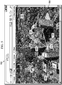
- model 234 displayed in graphical user interface 232 from Figure 2 is depicted in greater detail.
- model 234 is satellite image 300 of area 301.
- aircraft icon 302 and aircraft icon 304 are displayed in model 234.
- Aircraft icon 302 and aircraft icon 304 are graphical representations for unmanned aerial vehicle 204 and unmanned aerial vehicle 206, respectively, from Figure 2 .
- Aircraft icon 302 and aircraft icon 304 are displayed in model 234 in locations that correspond to the locations of unmanned aerial vehicle 204 and unmanned aerial vehicle 206, respectively, over area 301. Further, aircraft icon 302 and aircraft icon 304 are displayed having an orientation in model 234 that corresponds to an orientation of unmanned aerial vehicle 204 and unmanned aerial vehicle 206, respectively, over area 301.
- area 306 and area 308 are displayed in model 234.
- Area 306 represents a field of view for unmanned aerial vehicle 204 from Figure 2 .
- Area 308 represents a field of view for unmanned aerial vehicle 206 from Figure 2 .
- person icon 310 is present in area 306, and person icon 312 is present in area 308.
- Person icon 310 represents a person identified from a video data stream received from unmanned aerial vehicle 204 in Figure 2 .
- Person icon 312 represents a person identified from a video data stream received from unmanned aerial vehicle 206 in Figure 2 .
- path 314 is displayed in model 234 in association with person icon 310.
- Path 314 is a graphical representation of an expected path for person icon 310.
- path 314 has a direction that represents a direction of movement for the person represented by person icon 310.
- a viewer may select person icon 310 and/or person icon 312.
- a selection of person icon 310 causes image 316 to be displayed in association with person icon 310.
- Image 316 may be, for example, a portion of an image received in the video data stream from unmanned aerial vehicle 204 in Figure 2 .
- Image 316 is the portion of the image in the video data stream in which the person corresponding to person icon 310 was identified.
- Image 318 may be, for example, a portion of an image received in the video data stream from unmanned aerial vehicle 206 in Figure 2 .
- Image 318 is the portion of the image in the video data stream in which the person corresponding to person icon 312 was identified.
- a selection of person icon 310 causes window 320 to be displayed.
- Window 320 displays video 322.
- Video 322 is a presentation of the video data stream received from unmanned aerial vehicle 204 in Figure 2 .
- graphical indicator 324 is positioned over video 322 in window 320 to provide a location in video 322 for the person corresponding to person icon 310.
- Model 234 includes a representation of additional features in the area being monitored by unmanned aerial vehicle 204, unmanned aerial vehicle 206, and building 208 in Figure 2 .
- Portion 400 of model 234 may be selected for display in graphical user interface 232 in Figures 2-3 such that only a relevant portion of the area being monitored is displayed. Further, portion 400 may be selected for display such that an enlarged view of portion 400 of model 234 may be displayed.
- video processing environment 200 in Figure 2 and model 234 in Figures 2-4 are not meant to imply physical or architectural limitations to the manner in which an illustrative embodiment may be implemented.
- Other components in addition to and/or in place of the ones illustrated may be used. Some components may be unnecessary.
- the blocks are presented to illustrate some functional components. One or more of these blocks may be combined and/or divided into different blocks when implemented in an illustrative embodiment.
- additional platforms in addition to or in place of unmanned aerial vehicle 204, unmanned aerial vehicle 206, and/or building 208 may be present in number of platforms 202 in Figure 2 .
- additional computers in addition to computer 218 may be present in video processing environment 200 for processing the video data streams generated by the cameras for number of platforms 202.
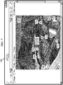
- model 500 displayed in graphical user interface 502 is an example of one implementation for model 135 displayed in graphical user interface 142 in Figure 1 .
- model 500 takes the form of common operating picture 504.
- Graphical representations 506, 508, 510, and 512 are displayed in model 500. These graphical representations represent objects identified in images of an area represented by model 500. The locations of these graphical representations may be updated in substantially real-time as the images of the area are received in substantially real-time.
- a selection of graphical representation 512 causes image 514 to be displayed. In this manner, a viewer may see the actual object represented by graphical representation 512.
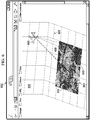
- model 600 displayed in graphical user interface 602 is another example of one implementation for model 135 displayed in graphical user interface 142 in Figure 1 .
- model 600 is a three-dimensional model.
- satellite image 604 of an area represented by model 600 is displayed with respect to grid 605 representing three-dimensional space in model 600.
- aircraft icon 606 is displayed with respect to grid 605 in a location relative to satellite image 604.
- Aircraft icon 606 represents an unmanned aerial vehicle that generates images for the area represented by model 600.
- the location and orientation for aircraft icon 606 in model 600 represents the location and orientation of the unmanned aerial vehicle with respect to the area represented by model 600.
- Area 608 represents different fields of view for the unmanned aerial vehicle over time.
- area 610 represents the field of view for the unmanned aerial vehicle at a first time at which an image was taken by the unmanned aerial vehicle.
- Area 612 represents the field of view for the unmanned aerial vehicle at a later time at which the image was taken by the unmanned aerial vehicle. In this manner, the unmanned aerial vehicle generates images over time as the unmanned aerial vehicle moves over the area represented by model 600.
- FIG. 7 an illustration of a graphical representation for an object displayed in a model displayed in a graphical user interface is depicted in accordance with an illustrative embodiment.
- a method is provided for geo-registering images taken by a plurality of stationary cameras to model 700.
- model 700, M is displayed in graphical user interface 702.
- Graphical representation 704 is for an object identified in an image generated by a stationary camera on, for example, a roof of a building or on the side of a tower.
- the plurality of stationary cameras generate a set of images, I 0 , I 1 , I 2 , ..., and I n , in which n is the total number of cameras.
- Geo-registering the images onto model 700 may be performed using homography. Homography is the mapping of one coordinate space to another coordinate space.
- H i,M denotes the homography mapping function that maps I i , an i th image in the sequence of images, to M, model 700.
- H i,M I i M i , where M i is the area in or portion of model 700 where I i projects to in model 700.
- H i,M I i may be referred to as a homography mapping.
- areas 706, 708, 710, 712, 714, and 716 are the areas in model 700 to which images may be projected using homography mappings H 1 , M I i through H 6 , M I 6 .
- Each area where the same homography mapping function is used is referred to as HI through H6, respectively, in Figure 7 .
- FIG. 8 an illustration of a three-dimensional space in a model is depicted in accordance with an illustrative embodiment.
- a method is provided for geo-registering images taken by cameras that can pan and/or tilt.
- a line of sight for camera 800 may be changed when camera 800 rotates.
- Camera 800 may rotate by panning and/or tilting.
- camera 800 rotates from position 802 to position 804. In position 802, camera 800 has line of sight 806.
- Camera 800 has line of sight 808 when in position 804.
- Model 810 represents a model of an area for which images are generated by camera 800.
- Three-dimensional surface 811 in model 810 represents an uneven ground surface for a ground for which images are taken by camera 800.
- Location 812 in model 810 represents an actual location of an object of interest.
- This object of interest is in different locations in image 814 generated by camera 800 in position 802 and in image 816 generated by camera 800 in position 804.
- the object of interest has location 818 in image 814 and location 820 in image 816.
- any coordinate for a location on the ground in an image generated by camera 800 may be mapped to a corresponding coordinate in model 810 using camera back projection.
- the coordinates for locations on the ground in the image may be calculated using extrinsic parameters and/or intrinsic parameters for camera 800, as well as information on where a line of sight from camera 800 intersects with the ground surface given the angle of rotation for camera 800. This information may be precalculated for all possible camera angles relative to the ground surface.
- Extrinsic parameters may include, for example, an amount of translation, an angle of rotation, and/or other suitable parameters for camera 800.
- Intrinsic parameters may include, for example, a focal length, a lens distortion, and/or other suitable parameters for camera 800.
- camera back projection maps a two-dimensional point in a camera image to a corresponding three-dimensional point in model 810.
- technique 900 includes steps 902, 904, 906, and 908. These steps are performed for each image generated by a camera that can rotate and/or move to different positions, such as, for example, a camera on an unmanned aerial vehicle.
- a current image in a sequence of images, I i may be registered with a previous image in the sequence of images, I i-1 , to obtain the homography mapping function, H i , i-1 .
- the current image and the previous image are consecutive images in a sequence of images generated by the camera.
- the homography mapping function may be obtained by matching features in the two images and then using a random sample consensus (RANSAC) algorithm to perform outlier filtering.
- the features matched are scale invariant feature transform (SIFT) features. These features do not vary when an image is scaled and/or rotated. The features may be matched using nearest neighbor matching techniques.
- SIFT scale invariant feature transform
- step 904 the homography mapping function, H i,M , for mapping the current image to the model is estimated using the homography mapping function identified for the previous image and the homography mapping function obtained in step 902.
- H' i,M H i-1,M H i,i-1 , where H' i,M is an estimation for H i,M , and H i-1,M is the homography mapping function for the previous image.
- the estimated homography mapping function warps current image, I i , to a partial local mosaic, M' i , in the model.
- M' i is the warped image of I i by H' I,m .
- M' i H' i , M I i .
- step 906 the area, M' i , is registered to the model at area, M i , to obtain H ⁇ , which is the homography mapping function needed to register M' i to the model at M i such that the current image is accurately registered to the model.
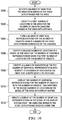
- FIG. 10 an illustration of a flowchart of a process for processing video data streams for an area is depicted in accordance with an illustrative embodiment.
- the process illustrated in Figure 10 may be implemented using video processing module 120 in video processing environment 100 in Figure 1 .
- the process begins by identifying a number of objects in the area from images in the video data streams for the area (operation 1000 ).
- the video data streams are generated by cameras.
- the cameras may be on a number of platforms, such as, for example, unmanned vehicles, manned vehicles, structures, and/or other suitable types of platforms.
- the number of objects is a number of objects of interest. In other words, the number of objects may include objects for which additional information and/or tracking is desired.
- the process then identifies a first number of locations in the area for the number of objects using the images in the video data streams (operation 1002 ).
- the first number of locations may be defined using a coordinate system for the images.
- the process forms a number of graphical representations for the number of objects using the images in the video data streams generated by the cameras (operation 1004 ).
- the number of graphical representations may be selected from, for example, object database 130 in Figure 1 .
- the process then identifies a second number of locations in a model of the area for the number of graphical representations using the first number of locations for the number of objects (operation 1006 ).
- the second number of locations may be defined by a geographic coordinate system for the model of the area.
- the geographic coordinate system may use, for example, latitude, longitude, and/or altitude.
- the coordinate system for the area in the images may map to the geographic coordinate system for the model. For example, a first location in the first number of locations for an object in the number of objects corresponds to a second location in the second number of locations for a corresponding graphical representation in the number of graphical representations.
- the process identifies a number of orientations for the number of graphical representations with respect to a number of features in the area that is represented in the model (operation 1008 ).
- an orientation for a graphical representation for an object corresponds to an actual orientation of the object in the area with respect to the number of features in the area.
- the process displays the number of graphical representations for the number of objects with the number of orientations identified in the second number of locations in the model of the area on a display system (operation 1010 ).
- the number of graphical representations may be displayed in the model with respect to the number of features in the area that is represented in the model.
- the process updates a display of the number of graphical representations in the model in the display system over time using the images in the video data streams received over time (operation 1012 ), with the process terminating thereafter.
- FIG. 11 an illustration of a flowchart of a process for identifying a number of objects in an area from images in video data streams for the area is depicted in accordance with an illustrative embodiment.
- the process illustrated in Figure 11 may be implemented using video processing module 120 in video processing environment 100 in Figure 1 . Further, this process may be used to implement operation 1000 in Figure 10 .
- the process begins by identifying objects present in the images in the video data streams (operation 1100 ). The process then selects an object from the identified objects for processing (operation 1102 ).
- the process determines whether additional information is desired for the object (operation 1104 ).
- the additional information may be, for example, data tracking movement of the object, a description of the object, and/or other suitable information about the object. If additional information is desired for the object, the process adds the object to a number of objects of interest (operation 1106 ).
- the process determines whether any additional objects that have been identified are present for processing (operation 1108 ). If additional objects are not present for processing, the process terminates. Otherwise, the process returns to operation 1102 as described above.
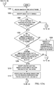
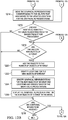
- FIGS 12A and 12B illustrations of a flowchart of a process for updating a display of graphical representations in a model is depicted in accordance with an illustrative embodiment.
- the process illustrated in Figure 11 may be implemented using video processing module 120 in video processing environment 100 in Figure 1 . Further, this process may be used to implement operation 1012 in Figure 10 .
- the process begins by receiving images in video data streams (operation 1200 ). These images may be received at a later time than the time at which initial images from which an initial number of objects of interest is identified.
- the process identifies objects in the images (operation 1202 ). Then, the process determines whether any of the objects identified have previously been identified as an object of interest (operation 1204 ).
- the process determines whether all of the objects previously identified as objects of interest are still objects of interest (operation 1206 ). If all of the objects previously identified are still objects of interest, the process determines whether any locations and/or orientations for the objects that are still objects of interest have changed from the locations and/or orientations previously identified for the objects (operation 1208 ).
- the process identifies updated locations and/or updated orientations for the objects that have moved (operation 1210 ). Thereafter, the process updates locations and/or orientations for the graphical representations for the objects that have moved (operation 1212 ) .
- the process moves the graphical representations corresponding to the objects that have moved to the updated locations for the graphical representations (operation 1214 ). Thereafter, the process determines whether any additional objects in the objects identified from the images are present for processing (operation 1215 ). If additional objects are present for processing, the process determines whether the objects are new objects of interest (operation 1216 ).
- the process determines whether any additional images are to be received (operation 1218 ). If additional images are not to be received, the process terminates. Otherwise, the process returns to operation 1200 as described above.
- the process adds these objects to the number of objects of interest (operation 1220 ).
- the process identifies locations for the new objects of interest (operation 1222 ).
- the process identifies graphical representations for the new objects of interest and locations and orientations for the graphical representations (operation 1224 ).
- the process displays the graphical representations for the new objects of interest in the model (operation 1226 ). The process then proceeds to operation 1218 as described above.
- the process removes the graphical representations corresponding to these objects from display in the model (operation 1228 ). The process then proceeds to operation 1215 as described above.
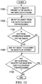
- FIG. 13 an illustration of a flowchart of a process for displaying information in association with a graphical representation in a model is depicted in accordance with an illustrative embodiment.
- the process illustrated in Figure 13 may be implemented using video processing module 120 in video processing environment 100 in Figure 1 .
- the process begins by waiting for user input selecting a graphical representation displayed in a model (operation 1300 ).
- user input may be received that selects a car icon in a model.
- the car icon may have a color indicating a color for the car it represents.
- the process then identifies information about an object represented by the graphical representation based on the user input (operation 1302 ).
- the information may be, for example, real-time video of the object, a description of the object, an identification of the object, a listing of features for the object, an image of the object, and/or other suitable types of information.
- the process may identify a make and/or model for the car represented by the car icon.
- the process displays the information about the object in association with the graphical representation representing the object in the model (operation 1304 ), with the process terminating thereafter.
- a balloon with text identifying the make and/or model of the car may be displayed extending from the car icon.
- each block in the flowcharts or block diagrams may represent a module, segment, or portion of computer usable or readable program code, which comprises one or more executable instructions for implementing the specified function or functions.
- the function or functions noted in the block may occur out of the order noted in the figures. For example, in some cases, two blocks shown in succession may be executed substantially concurrently, or the blocks may sometimes be executed in the reverse order, depending upon the functionality involved.
- data processing system 1400 includes communications fabric 1402, which provides communications between processor unit 1404, memory 1406, persistent storage 1408, communications unit 1410, input/output (I/O) unit 1412, and display 1414.
- communications fabric 1402 provides communications between processor unit 1404, memory 1406, persistent storage 1408, communications unit 1410, input/output (I/O) unit 1412, and display 1414.
- Processor unit 1404 serves to execute instructions for software that may be loaded into memory 1406.
- Processor unit 1404 may be a number of processors, a multi-processor core, or some other type of processor, depending on the particular implementation.
- a number, as used herein with reference to an item, means one or more items.
- processor unit 1404 may be implemented using a number of heterogeneous processor systems in which a main processor is present with secondary processors on a single chip.
- processor unit 1404 may be a symmetric multi-processor system containing multiple processors of the same type.
- Memory 1406 and persistent storage 1408 are examples of storage devices 1416.
- a storage device is any piece of hardware that is capable of storing information, such as, for example, without limitation, data, program code in functional form, and/or other suitable information either on a temporary basis and/or a permanent basis.
- Storage devices 1416 may also be referred to as computer readable storage devices in these examples.
- Memory 1406, in these examples, may be, for example, a random access memory or any other suitable volatile or non-volatile storage device.
- Persistent storage 1408 may take various forms, depending on the particular implementation.
- persistent storage 1408 may contain one or more components or devices.
- persistent storage 1408 may be a hard drive, a flash memory, a rewritable optical disk, a rewritable magnetic tape, or some combination of the above.
- the media used by persistent storage 1408 also may be removable.
- a removable hard drive may be used for persistent storage 1408.
- Communications unit 1410 in these examples, provides for communications with other data processing systems or devices.
- communications unit 1410 is a network interface card.
- Communications unit 1410 may provide communications through the use of either or both physical and wireless communications links.
- Input/output unit 1412 allows for input and output of data with other devices that may be connected to data processing system 1400.
- input/output unit 1412 may provide a connection for user input through a keyboard, a mouse, and/or some other suitable input device. Further, input/output unit 1412 may send output to a printer.
- Display 1414 provides a mechanism to display information to a user.
- Instructions for the operating system, applications, and/or programs may be located in storage devices 1416, which are in communication with processor unit 1404 through communications fabric 1402. In these illustrative examples, the instructions are in a functional form on persistent storage 1408. These instructions may be loaded into memory 1406 for execution by processor unit 1404. The processes of the different embodiments may be performed by processor unit 1404 using computer-implemented instructions, which may be located in a memory, such as memory 1406.
- program code computer usable program code
- computer readable program code that may be read and executed by a processor in processor unit 1404.
- the program code in the different embodiments may be embodied on different physical or computer readable storage media, such as memory 1406 or persistent storage 1408.
- Program code 1418 is located in a functional form on computer readable media 1420 that is selectively removable and may be loaded onto or transferred to data processing system 1400 for execution by processor unit 1404.
- Program code 1418 and computer readable media 1420 form computer program product 1422 in these examples.
- computer readable media 1420 may be computer readable storage media 1424 or computer readable signal media 1426.
- Computer readable storage media 1424 may include, for example, an optical or magnetic disk that is inserted or placed into a drive or other device that is part of persistent storage 1408 for transfer onto a storage device, such as a hard drive, that is part of persistent storage 1408.
- Computer readable storage media 1424 also may take the form of a persistent storage, such as a hard drive, a thumb drive, or a flash memory, that is connected to data processing system 1400. In some instances, computer readable storage media 1424 may not be removable from data processing system 1400.
- computer readable storage media 1424 is a physical or tangible storage device used to store program code 1418 rather than a medium that propagates or transmits program code 1418.
- Computer readable storage media 1424 is also referred to as a computer readable tangible storage device or a computer readable physical storage device. In other words, computer readable storage media 1424 is a media that can be touched by a person.
- program code 1418 may be transferred to data processing system 1400 using computer readable signal media 1426.
- Computer readable signal media 1426 may be, for example, a propagated data signal containing program code 1418.
- Computer readable signal media 1426 may be an electromagnetic signal, an optical signal, and/or any other suitable type of signal. These signals may be transmitted over communications links, such as wireless communications links, optical fiber cable, coaxial cable, a wire, and/or any other suitable type of communications link.
- the communications link and/or the connection may be physical or wireless in the illustrative examples.
- program code 1418 may be downloaded over a network to persistent storage 1408 from another device or data processing system through computer readable signal media 1426 for use within data processing system 1400.
- program code stored in a computer readable storage medium in a server data processing system may be downloaded over a network from the server to data processing system 1400.
- the data processing system providing program code 1418 may be a server computer, a client computer, or some other device capable of storing and transmitting program code 1418.
- the different components illustrated for data processing system 1400 are not meant to provide architectural limitations to the manner in which different embodiments may be implemented.
- the different illustrative embodiments may be implemented in a data processing system including components in addition to or in place of those illustrated for data processing system 1400.
- Other components shown in Figure 14 can be varied from the illustrative examples shown.
- the different embodiments may be implemented using any hardware device or system capable of running program code.
- the data processing system may include organic components integrated with inorganic components and/or may be comprised entirely of organic components excluding a human being.
- a storage device may be comprised of an organic semiconductor.
- processor unit 1404 may take the form of a hardware unit that has circuits that are manufactured or configured for a particular use. This type of hardware may perform operations without needing program code to be loaded into a memory from a storage device to be configured to perform the operations.
- processor unit 1404 when processor unit 1404 takes the form of a hardware unit, processor unit 1404 may be a circuit system, an application specific integrated circuit (ASIC), a programmable logic device, or some other suitable type of hardware configured to perform a number of operations.
- ASIC application specific integrated circuit
- a programmable logic device the device is configured to perform the number of operations. The device may be reconfigured at a later time or may be permanently configured to perform the number of operations.
- Examples of programmable logic devices include, for example, a programmable logic array, a programmable array logic, a field programmable logic array, a field programmable gate array, and other suitable hardware devices.
- program code 1418 may be omitted, because the processes for the different embodiments are implemented in a hardware unit.
- processor unit 1404 may be implemented using a combination of processors found in computers and hardware units.
- Processor unit 1404 may have a number of hardware units and a number of processors that are configured to run program code 1418. With this depicted example, some of the processes may be implemented in the number of hardware units, while other processes may be implemented in the number of processors.
- a bus system may be used to implement communications fabric 1402 and may be comprised of one or more buses, such as a system bus or an input/output bus.
- the bus system may be implemented using any suitable type of architecture that provides for a transfer of data between different components or devices attached to the bus system.
- a communications unit may include a number of devices that transmit data, receive data, or transmit and receive data.
- a communications unit may be, for example, a modem or a network adapter, two network adapters, or some combination thereof.
- a memory may be, for example, memory 1406, or a cache, such as found in an interface and memory controller hub that may be present in communications fabric 1402.
- the different illustrative embodiments provide a method and apparatus for processing video data streams for an area.
- a number of objects is identified in the area from images in the video data streams for the area.
- the video data streams are generated by cameras.
- a first number of locations is identified for the number of objects using the images in the video data streams.
- the first number of locations is defined using a coordinate system for the images.
- a number of graphical representations is formed for the number of objects using the images in the video data streams generated by the cameras.
- the number of graphical representations is displayed for the number of objects in a second number of locations in a model of the area on a display system with respect to a number of features in the area that is represented in the model.
- the second number of locations is defined using a geographic coordinate system for the model.
- a first location in the first number of locations for an object in the number of objects corresponds to a second location in the second number of locations for a corresponding graphical representation in the number of graphical representations.
Landscapes
- Engineering & Computer Science (AREA)
- Multimedia (AREA)
- Physics & Mathematics (AREA)
- General Physics & Mathematics (AREA)
- Human Computer Interaction (AREA)
- Signal Processing (AREA)
- General Engineering & Computer Science (AREA)
- Theoretical Computer Science (AREA)
- Library & Information Science (AREA)
- Processing Or Creating Images (AREA)
Claims (15)
- Verfahren zum Verarbeiten von Videodatenströmen (110) für einen Bereich (112), wobei das Verfahren Folgendes umfasst:Identifizieren einer Anzahl von Objekten (115) in dem Bereich (112) aus Bildern (114) in den Videodatenströmen (110) für den Bereich (112), wobei die Videodatenströme (110) durch Kameras (108) erzeugt werden;Identifizieren einer ersten Anzahl von Orten (122) für die Anzahl von Objekten (115) unter Verwendung der Bilder (114) in den Videodatenströmen (110), wobei die erste Anzahl von Orten (122) unter Verwendung eines Koordinatensystems (124) für die Bilder (114) definiert ist;Erzeugen einer Anzahl graphischer Darstellungen (126) für die Anzahl von Objekten (115) unter Verwendung der Bilder (114) in den Videodatenströmen (110), die durch die Kameras (108) erzeugt werden; undAnzeigen der Anzahl graphischer Darstellungen (126) für die Anzahl von Objekten (115) an einer zweiten Anzahl von Orten (132) in einem Modell (135) des Bereichs (112) auf einem Anzeigesystem (144) in Bezug auf eine Anzahl von Merkmalen (140) in dem Bereich (112), der in dem Modell (135) dargestellt wird, wobei die zweite Anzahl von Orten (132) unter Verwendung eines geographischen Koordinatensystems (134) für das Modell (135) definiert ist und ein erster Ort in der ersten Anzahl von Orten (122) für ein Objekt der Anzahl von Objekten (115) einem zweiten Ort in der zweiten Anzahl von Orten (132) für eine entsprechende graphische Darstellung (129) der Anzahl graphischer Darstellungen (126) entspricht, wobei jede graphische Darstellung der Anzahl graphischer Darstellungen ein Icon ist, wobei jedes Icon durch den Anwender auswählbar ist, um Informationen über das Objekt der Anzahl von Objekten, das durch das ausgewählte Icon dargestellt wird, anzuzeigen.
- Verfahren nach Anspruch 1, das ferner Folgendes umfasst:
Identifizieren der zweiten Anzahl von Orten (132) in dem Modell (135) des Bereichs (112), die der ersten Anzahl von Orten (122) für die Anzahl von Objekten (115) entspricht. - Verfahren nach Anspruch 1, das ferner Folgendes umfasst:
Identifizieren einer Anzahl von Orientierungen (138) für die Anzahl von Objekten (115) unter Verwendung der Bilder (114) in den Videodatenströmen (110); wobei der Schritt des Anzeigens der Anzahl graphischer Darstellungen (126) für die Anzahl von Objekten (115) an der zweiten Anzahl von Orten (132) in dem Modell (135) des Bereichs (112) auf dem Anzeigesystem (144) in Bezug auf die Anzahl von Merkmalen (140) in dem Bereich (112), der in dem Modell (135) dargestellt wird, Folgendes umfasst:
Anzeigen der Anzahl graphischer Darstellungen (126) für die Anzahl von Objekten (115) an der zweiten Anzahl von Orten (132) in dem Modell (135) des Bereichs (112) auf dem Anzeigesystem (144) zusammen mit der Anzahl von Orientierungen (138) in Bezug auf die Anzahl von Merkmalen (140) in dem Bereich (112), der in dem Modell (135) dargestellt wird. - Verfahren nach Anspruch 3, wobei der Schritt des Anzeigens der Anzahl graphischer Darstellungen (126) für die Anzahl von Objekten (115) an der zweiten Anzahl von Orten (132) in dem Modell (135) des Bereichs (112) auf dem Anzeigesystem (144) in Bezug auf die Anzahl von Merkmalen (140) in dem Bereich (112), der in dem Modell (135) dargestellt wird, ferner Folgendes umfasst:
Anzeigen von Informationen (148) über die Anzahl von Objekten (115) in Zuordnung zu der Anzahl graphischer Darstellungen (126) für die Anzahl von Objekten (115). - Verfahren nach Anspruch 1, wobei die erste Anzahl von Orten (122) ausgehend von einem ersten Anteil (154) der Bilder (114) in den Videodatenströmen (110), der zu einer ersten Zeit (156) erzeugt wird, identifiziert wird, das ferner Folgendes umfasst:Aktualisieren der ersten Anzahl von Orten (122) für die Anzahl von Objekten (115) unter Verwendung eines zweiten Anteils (158) der Bilder (114) in den Videodatenströmen (110), der zu einer zweiten Zeit (160), die später als die erste Zeit (156) ist, erzeugt wird, um eine aktualisierte erste Anzahl von Orten (162) zu erzeugen;Identifizieren einer aktualisierten zweiten Anzahl von Orten (164) in dem Modell (135) des Bereichs (112) unter Verwendung der aktualisierten ersten Anzahl von Orten (162); undAnzeigen der Anzahl graphischer Darstellungen (126) für die Anzahl von Objekten (115) an der aktualisierten zweiten Anzahl von Orten (164) in dem Modell (135) des Bereichs (112) auf dem Anzeigesystem (144) in Bezug auf die Anzahl von Merkmalen (140) in dem Bereich (112), der in dem Modell (135) dargestellt wird, wobei sich die Anzahl graphischer Darstellungen (126) für die Anzahl von Objekten (115) in dem Modell (135) auf eine Weise bewegt, die eine Bewegung der Anzahl von Objekten (115) in dem Bereich (112) darstellt.
- Verfahren nach Anspruch 1, das ferner folgendes umfasst:
Empfangen der Videodatenströme (110) für den Bereich (112) von einer Anzahl von Plattformen (102), wobei eine Plattform der Anzahl von Plattformen (102) aus einer mobilen Plattform oder einer stationären Plattform oder einer landbasierten Struktur oder einer wasserbasierten Struktur oder einer weltraumbasierten Struktur oder einem Fahrzeug oder einem Luftfahrzeug oder einem unbemannten Luftfahrzeug oder einem unbemannten Bodenfahrzeug gewählt ist. - Verfahren nach Anspruch 1, das ferner Folgendes umfasst:
Anzeigen einer Anzahl von Videos (168), die das Objekt der Anzahl von Objekten (115) enthalten, in Reaktion auf eine Anwendereingabe (150), die eine graphische Darstellung (129) der Anzahl graphischer Darstellungen (126) für das Objekt in dem Modell (135) auswählt. - Verfahren nach Anspruch 1, wobei das Modell (135) eine übliche Abbildung der Operationen für den Bereich (112) ist.
- Vorrichtung, die Folgendes umfasst:
ein Anzeigesystem (144); und ein Computersystem (104), das konfiguriert zum:Identifizieren einer Anzahl von Objekten (115) in einem Bereich (112) aus Bildern (114) in Videodatenströmen (110) für den Bereich (112), wobei die Videodatenströme (110) durch Kameras (108) erzeugt werden;Identifizieren einer ersten Anzahl von Orten (122) für die Anzahl von Objekten (115), wobei die erste Anzahl von Orten (122) unter Verwendung eines Koordinatensystems (124) für die Bilder (114) definiert ist;Erzeugen einer Anzahl graphischer Darstellungen (126) für die Anzahl von Objekten (115) unter Verwendung der Bilder (114) in den Videodatenströmen (110), die durch die Kameras (108) erzeugt werden; undAnzeigen der Anzahl graphischer Darstellungen (126) für die Anzahl von Objekten (115) an einer zweiten Anzahl von Orten (132) in einem Modell (135) des Bereichs (112) auf einem Anzeigesystem (144) in Bezug auf eine Anzahl von Merkmalen (140) in dem Bereich (112), die in dem Modell (135) dargestellt werden, wobei die zweite Anzahl von Orten (132) unter Verwendung eines geographischen Koordinatensystems (134) für das Modell (135) definiert ist und ein erster Ort der ersten Anzahl von Orten (122) für ein Objekt der Anzahl von Objekten (115) einem zweiten Ort der zweiten Anzahl von Orten (132) für eine entsprechende graphische Darstellung (129) der Anzahl graphischer Darstellungen (12t) entspricht, wobei jede graphische Darstellung der Anzahl graphischer Darstellungen ein Icon ist, wobei jedes Icon durch den Anwender auswählbar ist, um Informationen über das Objekt der Anzahl von Objekten, das durch das ausgewählte Icon dargestellt wird, anzuzeigen. - Vorrichtung nach Anspruch 9, wobei das Computersystem (104) ferner konfiguriert ist, die zweite Anzahl von Orten (132) in dem Modell (135) des Bereichs (112), die der ersten Anzahl von Orten (122) für die Anzahl von Objekten (115) entspricht, zu identifizieren.
- Vorrichtung nach Anspruch 9, wobei das Computersystem (104) ferner konfiguriert ist, eine Anzahl von Orientierungen (138) für die Anzahl von Objekten (115) unter Verwendung der Bilder (114) in den Videodatenströmen (110) zu identifizieren; und wobei das Computersystem (104), indem es konfiguriert ist zum Anzeigen der Anzahl graphischer Darstellungen (126) für die Anzahl von Objekten (115) an der zweiten Anzahl von Orten (132) in dem Modell (135) des Bereichs (112) auf dem Anzeigesystem (144) in Bezug auf die Anzahl von Merkmalen (140) in dem Bereich (112), der in dem Modell (135) dargestellt wird, konfiguriert ist zum Anzeigen der Anzahl graphischer Darstellungen (126) für die Anzahl von Objekten (115) an der zweiten Anzahl von Orten (132) in dem Modell (135) des Bereichs (112) auf dem Anzeigesystem (144) zusammen mit der Anzahl von Orientierungen (138) in Bezug auf die Anzahl von Merkmalen (140) in dem Bereich (112), der in dem Modell (135) dargestellt wird.
- Vorrichtung nach Anspruch 11, wobei das Computersystem (104), indem es konfiguriert ist zum Anzeigen der Anzahl graphischer Darstellungen (126) für die Anzahl von Objekten (115) an der zweiten Anzahl von Orten (132) in dem Modell (135) des Bereichs (112) auf dem Anzeigesystem (144) in Bezug auf die Anzahl von Merkmalen (140) in dem Bereich (112), der in dem Modell (135) dargestellt wird, konfiguriert ist zum Anzeigen von Informationen (148) über die Anzahl von Objekten (115) in Zuordnung zu der Anzahl graphischer Darstellungen (126) für die Anzahl von Objekten (115).
- Vorrichtung nach Anspruch 9, wobei die erste Anzahl von Orten (122) aus einem ersten Anteil (154) der Bilder (114) in den Videodatenströmen (110), der zu einer ersten Zeit (156) erzeugt wird, identifiziert wird und wobei das Computersystem (104) ferner konfiguriert zum Aktualisieren der ersten Anzahl von Orten (122) für die Anzahl von Objekten (115) unter Verwendung eines zweiten Anteils (158) der Bilder (114) in den Videodatenströmen (110), der zu einer zweiten Zeit (160), die später als die erste Zeit (156) ist, erzeugt wird, um eine aktualisierte erste Anzahl von Orten (162) zu erzeugen; Identifizieren einer aktualisierten zweiten Anzahl von Orten (164) in dem Modell (135) des Bereichs (112) unter Verwendung der aktualisierten ersten Anzahl von Orten (162); und Anzeigen der Anzahl graphischer Darstellungen (126) für die Anzahl von Objekten (115) an der aktualisierten zweiten Anzahl von Orten (164) in dem Modell (135) des Bereichs (112) auf dem Anzeigesystem (144) in Bezug auf die Anzahl von Merkmalen (140) in dem Bereich (112), der in dem Modell (135) dargestellt wird, wobei sich die Anzahl graphischer Darstellungen (126) für die Anzahl von Objekten (115) in dem Modell (135) auf eine Weise bewegt, die die Bewegung der Anzahl von Objekten (115) in dem Bereich (112) darstellt.
- Vorrichtung nach Anspruch 9, wobei das Computersystem (104) ferner konfiguriert ist zum Empfangen der Videodatenströme (110) für den Bereich (112) von einer Anzahl von Plattformen (102), wobei eine Plattform der Anzahl von Plattformen (102) aus einer mobilen Plattform oder einer stationären Plattform oder einer landbasierten Struktur oder einer wasserbasierten Struktur oder einer weltraumbasierten Struktur oder einem Fahrzeug oder einem Luftfahrzeug oder einem unbemannten Luftfahrzeug oder einem unbemannten Bodenfahrzeug ausgewählt ist.
- Vorrichtung nach Anspruch 9, wobei das Computersystem (104) ferner konfiguriert ist zum Anzeigen einer Anzahl von Videos (168), die das Objekt der Anzahl von Objekten (115) enthält, in Reaktion auf eine Anwendereingabe (150), die eine graphische Darstellung (129) der Anzahl graphischer Darstellungen (126) für das Objekt in dem Modell (135) auswählt.
Applications Claiming Priority (1)
| Application Number | Priority Date | Filing Date | Title |
|---|---|---|---|
| US13/113,295 US9746988B2 (en) | 2011-05-23 | 2011-05-23 | Multi-sensor surveillance system with a common operating picture |
Publications (2)
| Publication Number | Publication Date |
|---|---|
| EP2528047A1 EP2528047A1 (de) | 2012-11-28 |
| EP2528047B1 true EP2528047B1 (de) | 2018-08-08 |
Family
ID=45999567
Family Applications (1)
| Application Number | Title | Priority Date | Filing Date |
|---|---|---|---|
| EP12160213.0A Active EP2528047B1 (de) | 2011-05-23 | 2012-03-19 | Überwachungssystem mit mehreren Sensoren und einem gemeinsamen Betriebsbild |
Country Status (2)
| Country | Link |
|---|---|
| US (1) | US9746988B2 (de) |
| EP (1) | EP2528047B1 (de) |
Families Citing this family (23)
| Publication number | Priority date | Publication date | Assignee | Title |
|---|---|---|---|---|
| US8891820B2 (en) | 2011-09-29 | 2014-11-18 | The Boeing Company | Multi-modal sensor fusion |
| US9061102B2 (en) | 2012-07-17 | 2015-06-23 | Elwha Llc | Unmanned device interaction methods and systems |
| US20140024999A1 (en) | 2012-07-17 | 2014-01-23 | Elwha LLC, a limited liability company of the State of Delaware | Unmanned device utilization methods and systems |
| US9214021B2 (en) * | 2012-10-09 | 2015-12-15 | The Boeing Company | Distributed position identification |
| CN103020967A (zh) * | 2012-12-07 | 2013-04-03 | 青岛经纬蓝图信息技术有限公司 | 基于海岛边缘特征的无人机航拍图像精确匹配方法 |
| US9319641B2 (en) | 2013-07-24 | 2016-04-19 | The Boeing Company | Controlling movement of a camera to autonomously track a mobile object |
| US20150062339A1 (en) * | 2013-08-29 | 2015-03-05 | Brian Ostrom | Unmanned aircraft system for video and data communications |
| US9734399B2 (en) * | 2014-04-08 | 2017-08-15 | The Boeing Company | Context-aware object detection in aerial photographs/videos using travel path metadata |
| WO2016172262A1 (en) * | 2015-04-21 | 2016-10-27 | Placemeter, Inc. | Systems and methods for processing video data for activity monitoring |
| IL241200A0 (en) * | 2015-09-06 | 2015-11-30 | Unision Air Ltd | System and method for self-geo-location of an unmanned aerial vehicle |
| US10188580B2 (en) * | 2016-05-09 | 2019-01-29 | Toyota Motor Engineering & Manufacturing North America, Inc. | Systems and methods for providing environment information using an unmanned vehicle |
| TWI633786B (zh) * | 2016-12-15 | 2018-08-21 | 晶睿通訊股份有限公司 | 影像分析方法及攝影機 |
| US10572963B1 (en) * | 2017-07-14 | 2020-02-25 | Synapse Technology Corporation | Detection of items |
| US10546197B2 (en) | 2017-09-26 | 2020-01-28 | Ambient AI, Inc. | Systems and methods for intelligent and interpretive analysis of video image data using machine learning |
| JP6889274B2 (ja) * | 2017-10-17 | 2021-06-18 | 本田技研工業株式会社 | 走行モデル生成システム、走行モデル生成システムにおける車両、処理方法およびプログラム |
| US10628706B2 (en) * | 2018-05-11 | 2020-04-21 | Ambient AI, Inc. | Systems and methods for intelligent and interpretive analysis of sensor data and generating spatial intelligence using machine learning |
| US10452959B1 (en) | 2018-07-20 | 2019-10-22 | Synapse Tehnology Corporation | Multi-perspective detection of objects |
| US11195067B2 (en) | 2018-12-21 | 2021-12-07 | Ambient AI, Inc. | Systems and methods for machine learning-based site-specific threat modeling and threat detection |
| US11443515B2 (en) | 2018-12-21 | 2022-09-13 | Ambient AI, Inc. | Systems and methods for machine learning enhanced intelligent building access endpoint security monitoring and management |
| US11010605B2 (en) | 2019-07-30 | 2021-05-18 | Rapiscan Laboratories, Inc. | Multi-model detection of objects |
| US12149516B2 (en) * | 2020-06-02 | 2024-11-19 | Flex Integration, LLC | System and methods for tokenized hierarchical secured asset distribution |
| CN121420189A (zh) | 2023-06-01 | 2026-01-27 | 拉皮斯坎控股公司 | 用于在多个取向上自动生成对象的合成x射线扫描数据的系统和方法 |
| KR20250001725A (ko) * | 2023-06-29 | 2025-01-07 | 한화비전 주식회사 | 디지털 트윈을 이용한 스마트 관제 기술 |
Family Cites Families (54)
| Publication number | Priority date | Publication date | Assignee | Title |
|---|---|---|---|---|
| US4819169A (en) * | 1986-09-24 | 1989-04-04 | Nissan Motor Company, Limited | System and method for calculating movement direction and position of an unmanned vehicle |
| US5168530A (en) * | 1988-08-29 | 1992-12-01 | Raytheon Company | Confirmed boundary pattern matching |
| US5577181A (en) * | 1995-06-07 | 1996-11-19 | E-Systems, Inc. | Method for autonomous determination of tie points in imagery |
| US6985172B1 (en) * | 1995-12-01 | 2006-01-10 | Southwest Research Institute | Model-based incident detection system with motion classification |
| US6956573B1 (en) * | 1996-11-15 | 2005-10-18 | Sarnoff Corporation | Method and apparatus for efficiently representing storing and accessing video information |
| US6084510A (en) | 1997-04-18 | 2000-07-04 | Lemelson; Jerome H. | Danger warning and emergency response system and method |
| US6597818B2 (en) * | 1997-05-09 | 2003-07-22 | Sarnoff Corporation | Method and apparatus for performing geo-spatial registration of imagery |
| US6512857B1 (en) * | 1997-05-09 | 2003-01-28 | Sarnoff Corporation | Method and apparatus for performing geo-spatial registration |
| US6018349A (en) * | 1997-08-01 | 2000-01-25 | Microsoft Corporation | Patch-based alignment method and apparatus for construction of image mosaics |
| US6009190A (en) * | 1997-08-01 | 1999-12-28 | Microsoft Corporation | Texture map construction method and apparatus for displaying panoramic image mosaics |
| US6072496A (en) * | 1998-06-08 | 2000-06-06 | Microsoft Corporation | Method and system for capturing and representing 3D geometry, color and shading of facial expressions and other animated objects |
| US20020097322A1 (en) * | 2000-11-29 | 2002-07-25 | Monroe David A. | Multiple video display configurations and remote control of multiple video signals transmitted to a monitoring station over a network |
| US6985620B2 (en) * | 2000-03-07 | 2006-01-10 | Sarnoff Corporation | Method of pose estimation and model refinement for video representation of a three dimensional scene |
| US7522186B2 (en) * | 2000-03-07 | 2009-04-21 | L-3 Communications Corporation | Method and apparatus for providing immersive surveillance |
| IL136080A0 (en) * | 2000-05-11 | 2001-05-20 | Yeda Res & Dev | Sequence-to-sequence alignment |
| US6826292B1 (en) * | 2000-06-23 | 2004-11-30 | Sarnoff Corporation | Method and apparatus for tracking moving objects in a sequence of two-dimensional images using a dynamic layered representation |
| AU2002221023A1 (en) * | 2000-12-05 | 2002-06-18 | Yeda Research And Development Co..Ltd. | Apparatus and method for alignment of spatial or temporal non-overlapping image sequences |
| US7509241B2 (en) * | 2001-07-06 | 2009-03-24 | Sarnoff Corporation | Method and apparatus for automatically generating a site model |
| US20040179712A1 (en) | 2001-07-24 | 2004-09-16 | Gerrit Roelofsen | Method and sysem and data source for processing of image data |
| GB0119491D0 (en) * | 2001-08-10 | 2001-10-03 | Ibm | Improved orientation determination |
| US20030218674A1 (en) * | 2002-05-24 | 2003-11-27 | Sarnoff Corporation | Method and apparatus for video georegistration |
| WO2004004320A1 (en) * | 2002-07-01 | 2004-01-08 | The Regents Of The University Of California | Digital processing of video images |
| CA2505831C (en) * | 2002-11-12 | 2014-06-10 | Intellivid Corporation | Method and system for tracking and behavioral monitoring of multiple objects moving through multiple fields-of-view |
| US7826641B2 (en) * | 2004-01-30 | 2010-11-02 | Electronic Scripting Products, Inc. | Apparatus and method for determining an absolute pose of a manipulated object in a real three-dimensional environment with invariant features |
| US7187809B2 (en) * | 2004-06-10 | 2007-03-06 | Sarnoff Corporation | Method and apparatus for aligning video to three-dimensional point clouds |
| US8289390B2 (en) * | 2004-07-28 | 2012-10-16 | Sri International | Method and apparatus for total situational awareness and monitoring |
| US8102423B2 (en) | 2004-08-10 | 2012-01-24 | Sri International | Method and system for performing adaptive image acquisition |
| US6967612B1 (en) * | 2004-10-22 | 2005-11-22 | Gorman John D | System and method for standoff detection of human carried explosives |
| US8018489B2 (en) | 2005-02-04 | 2011-09-13 | Mccutchen David | Surveillance system |
| US7363157B1 (en) * | 2005-02-10 | 2008-04-22 | Sarnoff Corporation | Method and apparatus for performing wide area terrain mapping |
| WO2006105054A2 (en) * | 2005-03-25 | 2006-10-05 | Sarnoff Corporation | Method and system for improving video metadata through the use of frame-to-frame correspondences |
| US7353114B1 (en) * | 2005-06-27 | 2008-04-01 | Google Inc. | Markup language for an interactive geographic information system |
| US9363487B2 (en) * | 2005-09-08 | 2016-06-07 | Avigilon Fortress Corporation | Scanning camera-based video surveillance system |
| US9182228B2 (en) | 2006-02-13 | 2015-11-10 | Sony Corporation | Multi-lens array system and method |
| IL175835A0 (en) * | 2006-05-22 | 2007-07-04 | Rafael Armament Dev Authority | Methods and systems for communicating and displaying points-of-interest |
| WO2008044604A1 (en) * | 2006-10-04 | 2008-04-17 | Nikon Corporation | Electronic apparatus |
| WO2008044605A1 (en) * | 2006-10-04 | 2008-04-17 | Nikon Corporation | Electronic apparatus and electronic camera |
| JP4881766B2 (ja) * | 2007-03-06 | 2012-02-22 | パナソニック株式会社 | カメラ間連結関係情報生成装置 |
| US20100157056A1 (en) * | 2007-05-20 | 2010-06-24 | Rafael Advanced Defense Systems Ltd. | Tracking and imaging data fusion |
| JP5013961B2 (ja) * | 2007-05-21 | 2012-08-29 | キヤノン株式会社 | 位置姿勢計測装置及びその制御方法 |
| US8126260B2 (en) * | 2007-05-29 | 2012-02-28 | Cognex Corporation | System and method for locating a three-dimensional object using machine vision |
| EP2158576A1 (de) * | 2007-06-08 | 2010-03-03 | Tele Atlas B.V. | Verfahren und vorrichtung zum produzieren eines panoramas mit mehreren ansichtspunkten |
| US9251585B2 (en) * | 2007-07-12 | 2016-02-02 | Siemens Aktiengesellschaft | Coregistration and analysis of multi-modal images obtained in different geometries |
| US20090110267A1 (en) * | 2007-09-21 | 2009-04-30 | The Regents Of The University Of California | Automated texture mapping system for 3D models |
| US8264537B2 (en) * | 2007-09-28 | 2012-09-11 | The Mainz Group Llc | Photogrammetric networks for positional accuracy |
| EP2232463B1 (de) * | 2007-11-30 | 2018-04-11 | Searidge Technologies INC. | Flughafen-zielverfolgungssystem |
| US8098888B1 (en) * | 2008-01-28 | 2012-01-17 | Videomining Corporation | Method and system for automatic analysis of the trip of people in a retail space using multiple cameras |
| US7948502B2 (en) * | 2008-05-13 | 2011-05-24 | Mitac International Corp. | Method of displaying picture having location data and apparatus thereof |
| US8401276B1 (en) * | 2008-05-20 | 2013-03-19 | University Of Southern California | 3-D reconstruction and registration |
| US8284190B2 (en) * | 2008-06-25 | 2012-10-09 | Microsoft Corporation | Registration of street-level imagery to 3D building models |
| WO2010045271A1 (en) * | 2008-10-14 | 2010-04-22 | Joshua Victor Aller | Target and method of detecting, identifying, and determining 3-d pose of the target |
| US20100238161A1 (en) * | 2009-03-19 | 2010-09-23 | Kenneth Varga | Computer-aided system for 360º heads up display of safety/mission critical data |
| FR2953940B1 (fr) * | 2009-12-16 | 2012-02-03 | Thales Sa | Procede de geo-referencement d'une zone imagee |
| IL204089A (en) * | 2010-02-21 | 2014-06-30 | Elbit Systems Ltd | A method and system for detection and tracking based on frequency multiplicity and multiplicity |
-
2011
- 2011-05-23 US US13/113,295 patent/US9746988B2/en active Active
-
2012
- 2012-03-19 EP EP12160213.0A patent/EP2528047B1/de active Active
Non-Patent Citations (1)
| Title |
|---|
| None * |
Also Published As
| Publication number | Publication date |
|---|---|
| EP2528047A1 (de) | 2012-11-28 |
| US20120304085A1 (en) | 2012-11-29 |
| US9746988B2 (en) | 2017-08-29 |
Similar Documents
| Publication | Publication Date | Title |
|---|---|---|
| US9746988B2 (en) | Multi-sensor surveillance system with a common operating picture | |
| US20250013235A1 (en) | Systems and Methods for Simultaneous Localization and Mapping Using Asynchronous Multi-View Cameras | |
| US11415986B2 (en) | Geocoding data for an automated vehicle | |
| US10061486B2 (en) | Area monitoring system implementing a virtual environment | |
| US8624709B2 (en) | System and method for camera control in a surveillance system | |
| EP2575104B1 (de) | Videoverbesserung mit hoher Auflösung | |
| US12092479B2 (en) | Map feature identification using motion data and surfel data | |
| US8314816B2 (en) | System and method for displaying information on a display element | |
| CN112204343A (zh) | 高清晰地图数据的可视化 | |
| EP2830028B1 (de) | Steuerung der bewegung einer kamera zur autonomen verfolgung eines mobilen objekts | |
| US20140226024A1 (en) | Camera control in presence of latency | |
| CN109656319B (zh) | 一种用于呈现地面行动辅助信息方法与设备 | |
| US20240345577A1 (en) | Geocoding data for an automated vehicle | |
| US9534902B2 (en) | Time phased imagery for an artificial point of view | |
| EP2641395B1 (de) | System und verfahren zur kamerasteuerung in einem überwachungssystem | |
| US9565403B1 (en) | Video processing system | |
| JP7764784B2 (ja) | 情報処理装置、情報処理方法、プログラム及びシステム | |
| CN103380618B (zh) | 用于监视系统中的摄像机控制的系统和方法 | |
| WO2025080383A1 (en) | Systems and methods of remote dynamic visualization of situations to be navigated by autonomous vehicles |
Legal Events
| Date | Code | Title | Description |
|---|---|---|---|
| PUAI | Public reference made under article 153(3) epc to a published international application that has entered the european phase |
Free format text: ORIGINAL CODE: 0009012 |
|
| 17P | Request for examination filed |
Effective date: 20120319 |
|
| AK | Designated contracting states |
Kind code of ref document: A1 Designated state(s): AL AT BE BG CH CY CZ DE DK EE ES FI FR GB GR HR HU IE IS IT LI LT LU LV MC MK MT NL NO PL PT RO RS SE SI SK SM TR |
|
| AX | Request for extension of the european patent |
Extension state: BA ME |
|
| STAA | Information on the status of an ep patent application or granted ep patent |
Free format text: STATUS: EXAMINATION IS IN PROGRESS |
|
| 17Q | First examination report despatched |
Effective date: 20170620 |
|
| GRAP | Despatch of communication of intention to grant a patent |
Free format text: ORIGINAL CODE: EPIDOSNIGR1 |
|
| STAA | Information on the status of an ep patent application or granted ep patent |
Free format text: STATUS: GRANT OF PATENT IS INTENDED |
|
| INTG | Intention to grant announced |
Effective date: 20180226 |
|
| GRAS | Grant fee paid |
Free format text: ORIGINAL CODE: EPIDOSNIGR3 |
|
| GRAA | (expected) grant |
Free format text: ORIGINAL CODE: 0009210 |
|
| STAA | Information on the status of an ep patent application or granted ep patent |
Free format text: STATUS: THE PATENT HAS BEEN GRANTED |
|
| AK | Designated contracting states |
Kind code of ref document: B1 Designated state(s): AL AT BE BG CH CY CZ DE DK EE ES FI FR GB GR HR HU IE IS IT LI LT LU LV MC MK MT NL NO PL PT RO RS SE SI SK SM TR |
|
| REG | Reference to a national code |
Ref country code: GB Ref legal event code: FG4D |
|
| REG | Reference to a national code |
Ref country code: CH Ref legal event code: EP Ref country code: AT Ref legal event code: REF Ref document number: 1027904 Country of ref document: AT Kind code of ref document: T Effective date: 20180815 |
|
| REG | Reference to a national code |
Ref country code: IE Ref legal event code: FG4D |
|
| REG | Reference to a national code |
Ref country code: DE Ref legal event code: R096 Ref document number: 602012049346 Country of ref document: DE |
|
| REG | Reference to a national code |
Ref country code: NL Ref legal event code: MP Effective date: 20180808 |
|
| REG | Reference to a national code |
Ref country code: LT Ref legal event code: MG4D |
|
| REG | Reference to a national code |
Ref country code: AT Ref legal event code: MK05 Ref document number: 1027904 Country of ref document: AT Kind code of ref document: T Effective date: 20180808 |
|
| PG25 | Lapsed in a contracting state [announced via postgrant information from national office to epo] |
Ref country code: PL Free format text: LAPSE BECAUSE OF FAILURE TO SUBMIT A TRANSLATION OF THE DESCRIPTION OR TO PAY THE FEE WITHIN THE PRESCRIBED TIME-LIMIT Effective date: 20180808 Ref country code: AT Free format text: LAPSE BECAUSE OF FAILURE TO SUBMIT A TRANSLATION OF THE DESCRIPTION OR TO PAY THE FEE WITHIN THE PRESCRIBED TIME-LIMIT Effective date: 20180808 Ref country code: IS Free format text: LAPSE BECAUSE OF FAILURE TO SUBMIT A TRANSLATION OF THE DESCRIPTION OR TO PAY THE FEE WITHIN THE PRESCRIBED TIME-LIMIT Effective date: 20181208 Ref country code: SE Free format text: LAPSE BECAUSE OF FAILURE TO SUBMIT A TRANSLATION OF THE DESCRIPTION OR TO PAY THE FEE WITHIN THE PRESCRIBED TIME-LIMIT Effective date: 20180808 Ref country code: GR Free format text: LAPSE BECAUSE OF FAILURE TO SUBMIT A TRANSLATION OF THE DESCRIPTION OR TO PAY THE FEE WITHIN THE PRESCRIBED TIME-LIMIT Effective date: 20181109 Ref country code: RS Free format text: LAPSE BECAUSE OF FAILURE TO SUBMIT A TRANSLATION OF THE DESCRIPTION OR TO PAY THE FEE WITHIN THE PRESCRIBED TIME-LIMIT Effective date: 20180808 Ref country code: FI Free format text: LAPSE BECAUSE OF FAILURE TO SUBMIT A TRANSLATION OF THE DESCRIPTION OR TO PAY THE FEE WITHIN THE PRESCRIBED TIME-LIMIT Effective date: 20180808 Ref country code: NO Free format text: LAPSE BECAUSE OF FAILURE TO SUBMIT A TRANSLATION OF THE DESCRIPTION OR TO PAY THE FEE WITHIN THE PRESCRIBED TIME-LIMIT Effective date: 20181108 Ref country code: NL Free format text: LAPSE BECAUSE OF FAILURE TO SUBMIT A TRANSLATION OF THE DESCRIPTION OR TO PAY THE FEE WITHIN THE PRESCRIBED TIME-LIMIT Effective date: 20180808 Ref country code: BG Free format text: LAPSE BECAUSE OF FAILURE TO SUBMIT A TRANSLATION OF THE DESCRIPTION OR TO PAY THE FEE WITHIN THE PRESCRIBED TIME-LIMIT Effective date: 20181108 Ref country code: LT Free format text: LAPSE BECAUSE OF FAILURE TO SUBMIT A TRANSLATION OF THE DESCRIPTION OR TO PAY THE FEE WITHIN THE PRESCRIBED TIME-LIMIT Effective date: 20180808 |
|
| PG25 | Lapsed in a contracting state [announced via postgrant information from national office to epo] |
Ref country code: HR Free format text: LAPSE BECAUSE OF FAILURE TO SUBMIT A TRANSLATION OF THE DESCRIPTION OR TO PAY THE FEE WITHIN THE PRESCRIBED TIME-LIMIT Effective date: 20180808 Ref country code: LV Free format text: LAPSE BECAUSE OF FAILURE TO SUBMIT A TRANSLATION OF THE DESCRIPTION OR TO PAY THE FEE WITHIN THE PRESCRIBED TIME-LIMIT Effective date: 20180808 Ref country code: AL Free format text: LAPSE BECAUSE OF FAILURE TO SUBMIT A TRANSLATION OF THE DESCRIPTION OR TO PAY THE FEE WITHIN THE PRESCRIBED TIME-LIMIT Effective date: 20180808 |
|
| PG25 | Lapsed in a contracting state [announced via postgrant information from national office to epo] |
Ref country code: CZ Free format text: LAPSE BECAUSE OF FAILURE TO SUBMIT A TRANSLATION OF THE DESCRIPTION OR TO PAY THE FEE WITHIN THE PRESCRIBED TIME-LIMIT Effective date: 20180808 Ref country code: RO Free format text: LAPSE BECAUSE OF FAILURE TO SUBMIT A TRANSLATION OF THE DESCRIPTION OR TO PAY THE FEE WITHIN THE PRESCRIBED TIME-LIMIT Effective date: 20180808 Ref country code: ES Free format text: LAPSE BECAUSE OF FAILURE TO SUBMIT A TRANSLATION OF THE DESCRIPTION OR TO PAY THE FEE WITHIN THE PRESCRIBED TIME-LIMIT Effective date: 20180808 Ref country code: EE Free format text: LAPSE BECAUSE OF FAILURE TO SUBMIT A TRANSLATION OF THE DESCRIPTION OR TO PAY THE FEE WITHIN THE PRESCRIBED TIME-LIMIT Effective date: 20180808 Ref country code: IT Free format text: LAPSE BECAUSE OF FAILURE TO SUBMIT A TRANSLATION OF THE DESCRIPTION OR TO PAY THE FEE WITHIN THE PRESCRIBED TIME-LIMIT Effective date: 20180808 |
|
| REG | Reference to a national code |
Ref country code: DE Ref legal event code: R097 Ref document number: 602012049346 Country of ref document: DE |
|
| PG25 | Lapsed in a contracting state [announced via postgrant information from national office to epo] |
Ref country code: SM Free format text: LAPSE BECAUSE OF FAILURE TO SUBMIT A TRANSLATION OF THE DESCRIPTION OR TO PAY THE FEE WITHIN THE PRESCRIBED TIME-LIMIT Effective date: 20180808 Ref country code: DK Free format text: LAPSE BECAUSE OF FAILURE TO SUBMIT A TRANSLATION OF THE DESCRIPTION OR TO PAY THE FEE WITHIN THE PRESCRIBED TIME-LIMIT Effective date: 20180808 Ref country code: SK Free format text: LAPSE BECAUSE OF FAILURE TO SUBMIT A TRANSLATION OF THE DESCRIPTION OR TO PAY THE FEE WITHIN THE PRESCRIBED TIME-LIMIT Effective date: 20180808 |
|
| PLBE | No opposition filed within time limit |
Free format text: ORIGINAL CODE: 0009261 |
|
| STAA | Information on the status of an ep patent application or granted ep patent |
Free format text: STATUS: NO OPPOSITION FILED WITHIN TIME LIMIT |
|
| 26N | No opposition filed |
Effective date: 20190509 |
|
| PG25 | Lapsed in a contracting state [announced via postgrant information from national office to epo] |
Ref country code: SI Free format text: LAPSE BECAUSE OF FAILURE TO SUBMIT A TRANSLATION OF THE DESCRIPTION OR TO PAY THE FEE WITHIN THE PRESCRIBED TIME-LIMIT Effective date: 20180808 |
|
| PG25 | Lapsed in a contracting state [announced via postgrant information from national office to epo] |
Ref country code: MC Free format text: LAPSE BECAUSE OF FAILURE TO SUBMIT A TRANSLATION OF THE DESCRIPTION OR TO PAY THE FEE WITHIN THE PRESCRIBED TIME-LIMIT Effective date: 20180808 |
|
| REG | Reference to a national code |
Ref country code: CH Ref legal event code: PL |
|
| PG25 | Lapsed in a contracting state [announced via postgrant information from national office to epo] |
Ref country code: LU Free format text: LAPSE BECAUSE OF NON-PAYMENT OF DUE FEES Effective date: 20190319 |
|
| REG | Reference to a national code |
Ref country code: BE Ref legal event code: MM Effective date: 20190331 |
|
| REG | Reference to a national code |
Ref country code: DE Ref legal event code: R082 Ref document number: 602012049346 Country of ref document: DE Representative=s name: MAIER, LL.M., MICHAEL C., DE Ref country code: DE Ref legal event code: R082 Ref document number: 602012049346 Country of ref document: DE Representative=s name: BOULT WADE TENNANT LLP, DE |
|
| PG25 | Lapsed in a contracting state [announced via postgrant information from national office to epo] |
Ref country code: IE Free format text: LAPSE BECAUSE OF NON-PAYMENT OF DUE FEES Effective date: 20190319 Ref country code: CH Free format text: LAPSE BECAUSE OF NON-PAYMENT OF DUE FEES Effective date: 20190331 Ref country code: LI Free format text: LAPSE BECAUSE OF NON-PAYMENT OF DUE FEES Effective date: 20190331 |
|
| REG | Reference to a national code |
Ref country code: DE Ref legal event code: R082 Ref document number: 602012049346 Country of ref document: DE Representative=s name: BOULT WADE TENNANT LLP, DE |
|
| PG25 | Lapsed in a contracting state [announced via postgrant information from national office to epo] |
Ref country code: BE Free format text: LAPSE BECAUSE OF NON-PAYMENT OF DUE FEES Effective date: 20190331 |
|
| PG25 | Lapsed in a contracting state [announced via postgrant information from national office to epo] |
Ref country code: TR Free format text: LAPSE BECAUSE OF FAILURE TO SUBMIT A TRANSLATION OF THE DESCRIPTION OR TO PAY THE FEE WITHIN THE PRESCRIBED TIME-LIMIT Effective date: 20180808 |
|
| PG25 | Lapsed in a contracting state [announced via postgrant information from national office to epo] |
Ref country code: PT Free format text: LAPSE BECAUSE OF FAILURE TO SUBMIT A TRANSLATION OF THE DESCRIPTION OR TO PAY THE FEE WITHIN THE PRESCRIBED TIME-LIMIT Effective date: 20181208 Ref country code: MT Free format text: LAPSE BECAUSE OF NON-PAYMENT OF DUE FEES Effective date: 20190319 |
|
| PG25 | Lapsed in a contracting state [announced via postgrant information from national office to epo] |
Ref country code: CY Free format text: LAPSE BECAUSE OF FAILURE TO SUBMIT A TRANSLATION OF THE DESCRIPTION OR TO PAY THE FEE WITHIN THE PRESCRIBED TIME-LIMIT Effective date: 20180808 |
|
| PG25 | Lapsed in a contracting state [announced via postgrant information from national office to epo] |
Ref country code: HU Free format text: LAPSE BECAUSE OF FAILURE TO SUBMIT A TRANSLATION OF THE DESCRIPTION OR TO PAY THE FEE WITHIN THE PRESCRIBED TIME-LIMIT; INVALID AB INITIO Effective date: 20120319 |
|
| PG25 | Lapsed in a contracting state [announced via postgrant information from national office to epo] |
Ref country code: MK Free format text: LAPSE BECAUSE OF FAILURE TO SUBMIT A TRANSLATION OF THE DESCRIPTION OR TO PAY THE FEE WITHIN THE PRESCRIBED TIME-LIMIT Effective date: 20180808 |
|
| P01 | Opt-out of the competence of the unified patent court (upc) registered |
Effective date: 20230516 |
|
| PGFP | Annual fee paid to national office [announced via postgrant information from national office to epo] |
Ref country code: GB Payment date: 20260327 Year of fee payment: 15 |
|
| PGFP | Annual fee paid to national office [announced via postgrant information from national office to epo] |
Ref country code: DE Payment date: 20260327 Year of fee payment: 15 |
|
| PGFP | Annual fee paid to national office [announced via postgrant information from national office to epo] |
Ref country code: FR Payment date: 20260325 Year of fee payment: 15 |