EP2527684A2 - Seil mit Spiralenzähnen - Google Patents
Seil mit Spiralenzähnen Download PDFInfo
- Publication number
- EP2527684A2 EP2527684A2 EP12163386A EP12163386A EP2527684A2 EP 2527684 A2 EP2527684 A2 EP 2527684A2 EP 12163386 A EP12163386 A EP 12163386A EP 12163386 A EP12163386 A EP 12163386A EP 2527684 A2 EP2527684 A2 EP 2527684A2
- Authority
- EP
- European Patent Office
- Prior art keywords
- rope
- resin
- infrared reflectance
- spiral teeth
- adjusting material
- Prior art date
- Legal status (The legal status is an assumption and is not a legal conclusion. Google has not performed a legal analysis and makes no representation as to the accuracy of the status listed.)
- Withdrawn
Links
- 229920005989 resin Polymers 0.000 claims abstract description 195
- 239000011347 resin Substances 0.000 claims abstract description 195
- 239000000463 material Substances 0.000 claims abstract description 89
- 239000011162 core material Substances 0.000 claims abstract description 46
- 239000000049 pigment Substances 0.000 claims description 32
- 238000000034 method Methods 0.000 claims description 31
- 230000008569 process Effects 0.000 claims description 24
- 238000004519 manufacturing process Methods 0.000 claims description 14
- GWEVSGVZZGPLCZ-UHFFFAOYSA-N Titan oxide Chemical compound O=[Ti]=O GWEVSGVZZGPLCZ-UHFFFAOYSA-N 0.000 claims description 8
- OGIDPMRJRNCKJF-UHFFFAOYSA-N titanium oxide Inorganic materials [Ti]=O OGIDPMRJRNCKJF-UHFFFAOYSA-N 0.000 claims description 8
- 239000006229 carbon black Substances 0.000 claims description 7
- 239000002131 composite material Substances 0.000 claims description 7
- 238000004804 winding Methods 0.000 claims description 6
- 238000010438 heat treatment Methods 0.000 claims description 5
- 239000002243 precursor Substances 0.000 claims description 4
- 229920005992 thermoplastic resin Polymers 0.000 claims description 4
- 239000011248 coating agent Substances 0.000 abstract description 9
- 238000000576 coating method Methods 0.000 abstract description 9
- 239000000975 dye Substances 0.000 description 19
- 229920001971 elastomer Polymers 0.000 description 19
- 239000000806 elastomer Substances 0.000 description 19
- 229920000728 polyester Polymers 0.000 description 17
- 229910001220 stainless steel Inorganic materials 0.000 description 10
- 239000010935 stainless steel Substances 0.000 description 10
- 239000000853 adhesive Substances 0.000 description 8
- 230000001070 adhesive effect Effects 0.000 description 8
- 230000009191 jumping Effects 0.000 description 8
- 230000000052 comparative effect Effects 0.000 description 6
- 230000000694 effects Effects 0.000 description 6
- 230000006866 deterioration Effects 0.000 description 3
- 239000000843 powder Substances 0.000 description 3
- YCKRFDGAMUMZLT-UHFFFAOYSA-N Fluorine atom Chemical compound [F] YCKRFDGAMUMZLT-UHFFFAOYSA-N 0.000 description 2
- UQSXHKLRYXJYBZ-UHFFFAOYSA-N Iron oxide Chemical compound [Fe]=O UQSXHKLRYXJYBZ-UHFFFAOYSA-N 0.000 description 2
- 239000004952 Polyamide Substances 0.000 description 2
- 229920006362 Teflon® Polymers 0.000 description 2
- 229910045601 alloy Inorganic materials 0.000 description 2
- 239000000956 alloy Substances 0.000 description 2
- PYKYMHQGRFAEBM-UHFFFAOYSA-N anthraquinone Natural products CCC(=O)c1c(O)c2C(=O)C3C(C=CC=C3O)C(=O)c2cc1CC(=O)OC PYKYMHQGRFAEBM-UHFFFAOYSA-N 0.000 description 2
- 150000004056 anthraquinones Chemical class 0.000 description 2
- 229910001566 austenite Inorganic materials 0.000 description 2
- 239000011737 fluorine Substances 0.000 description 2
- 229910052731 fluorine Inorganic materials 0.000 description 2
- IEQIEDJGQAUEQZ-UHFFFAOYSA-N phthalocyanine Chemical compound N1C(N=C2C3=CC=CC=C3C(N=C3C4=CC=CC=C4C(=N4)N3)=N2)=C(C=CC=C2)C2=C1N=C1C2=CC=CC=C2C4=N1 IEQIEDJGQAUEQZ-UHFFFAOYSA-N 0.000 description 2
- 229920002647 polyamide Polymers 0.000 description 2
- 229920006122 polyamide resin Polymers 0.000 description 2
- 229920001225 polyester resin Polymers 0.000 description 2
- 239000004645 polyester resin Substances 0.000 description 2
- 229920005672 polyolefin resin Polymers 0.000 description 2
- 229920003225 polyurethane elastomer Polymers 0.000 description 2
- 229920005749 polyurethane resin Polymers 0.000 description 2
- 239000004606 Fillers/Extenders Substances 0.000 description 1
- NRCMAYZCPIVABH-UHFFFAOYSA-N Quinacridone Chemical compound N1C2=CC=CC=C2C(=O)C2=C1C=C1C(=O)C3=CC=CC=C3NC1=C2 NRCMAYZCPIVABH-UHFFFAOYSA-N 0.000 description 1
- 238000001354 calcination Methods 0.000 description 1
- 239000003086 colorant Substances 0.000 description 1
- PPSZHCXTGRHULJ-UHFFFAOYSA-N dioxazine Chemical compound O1ON=CC=C1 PPSZHCXTGRHULJ-UHFFFAOYSA-N 0.000 description 1
- 229910001039 duplex stainless steel Inorganic materials 0.000 description 1
- AEOCXXJPGCBFJA-UHFFFAOYSA-N ethionamide Chemical compound CCC1=CC(C(N)=S)=CC=N1 AEOCXXJPGCBFJA-UHFFFAOYSA-N 0.000 description 1
- 238000011156 evaluation Methods 0.000 description 1
- KHYBPSFKEHXSLX-UHFFFAOYSA-N iminotitanium Chemical compound [Ti]=N KHYBPSFKEHXSLX-UHFFFAOYSA-N 0.000 description 1
- 239000012948 isocyanate Substances 0.000 description 1
- 150000002513 isocyanates Chemical class 0.000 description 1
- PXZQEOJJUGGUIB-UHFFFAOYSA-N isoindolin-1-one Chemical compound C1=CC=C2C(=O)NCC2=C1 PXZQEOJJUGGUIB-UHFFFAOYSA-N 0.000 description 1
- 238000002844 melting Methods 0.000 description 1
- 230000008018 melting Effects 0.000 description 1
- 239000002184 metal Substances 0.000 description 1
- 229910052751 metal Inorganic materials 0.000 description 1
- 238000002156 mixing Methods 0.000 description 1
- 238000012986 modification Methods 0.000 description 1
- 230000004048 modification Effects 0.000 description 1
- 229910001000 nickel titanium Inorganic materials 0.000 description 1
- -1 polymethylene Polymers 0.000 description 1
- 230000009467 reduction Effects 0.000 description 1
- 239000000126 substance Substances 0.000 description 1
- OKYDCMQQLGECPI-UHFFFAOYSA-N thiopyrylium Chemical compound C1=CC=[S+]C=C1 OKYDCMQQLGECPI-UHFFFAOYSA-N 0.000 description 1
- WFKWXMTUELFFGS-UHFFFAOYSA-N tungsten Chemical compound [W] WFKWXMTUELFFGS-UHFFFAOYSA-N 0.000 description 1
- 229910052721 tungsten Inorganic materials 0.000 description 1
- 239000010937 tungsten Substances 0.000 description 1
- 229910000859 α-Fe Inorganic materials 0.000 description 1
Images
Classifications
-
- F—MECHANICAL ENGINEERING; LIGHTING; HEATING; WEAPONS; BLASTING
- F16—ENGINEERING ELEMENTS AND UNITS; GENERAL MEASURES FOR PRODUCING AND MAINTAINING EFFECTIVE FUNCTIONING OF MACHINES OR INSTALLATIONS; THERMAL INSULATION IN GENERAL
- F16G—BELTS, CABLES, OR ROPES, PREDOMINANTLY USED FOR DRIVING PURPOSES; CHAINS; FITTINGS PREDOMINANTLY USED THEREFOR
- F16G9/00—Ropes or cables specially adapted for driving, or for being driven by, pulleys or other gearing elements
-
- D—TEXTILES; PAPER
- D07—ROPES; CABLES OTHER THAN ELECTRIC
- D07B—ROPES OR CABLES IN GENERAL
- D07B2207/00—Rope or cable making machines
- D07B2207/40—Machine components
- D07B2207/404—Heat treating devices; Corresponding methods
- D07B2207/4059—Heat treating devices; Corresponding methods to soften the filler material
-
- D—TEXTILES; PAPER
- D07—ROPES; CABLES OTHER THAN ELECTRIC
- D07B—ROPES OR CABLES IN GENERAL
- D07B5/00—Making ropes or cables from special materials or of particular form
- D07B5/005—Making ropes or cables from special materials or of particular form characterised by their outer shape or surface properties
Definitions
- the present invention relates to a rope with spiral teeth.
- a rope with spiral teeth has been used to accurately and quietly move a carriage of a printer or a movable member such as a scanner.
- JP-A-2004-239347 and JP-A-2001-241514 disclose a rope with spiral teeth.
- the rope with spiral teeth includes a rope body and a wiring body wound around the outer circumferential surface of the rope body.
- the rope body includes a wire rope serving as a core material and a first resin covering the wire rope.
- the wiring body includes a core material and a second resin covering the core material.
- the rope body (first resin) and the wiring body (second resin) are bonded with an isocyanate-based adhesive. Therefore, the bonding strength may be reduced due to the adhesive being unevenly coated. The reduction in bonding strength may cause the wiring body to peel off the rope body while in use.
- the rope with spiral teeth also includes a spiral protrusion formed of the wiring body.
- the protrusion needs to have a predetermined shape that hardly changes. That is, the wiring body needs to be constantly and securely engaged with a groove of a gear. In the case where the protrusion is not kept in the predetermined shape, it is difficult for the wiring body to engage with the groove of the gear. As a result, so- called "tooth jumping" may occur.
- the first resin and the second resin need to have excellent durability.
- An object of the present invention is to provide a rope with spiral teeth in which the above problems of, for example, an adhesive being coated unevenly does not occur in production and the bonding strength between first and second ropes is high.
- This object is solved by a rope with spiral teeth according to claim 1 and a method for manufacturing such a rope with spiral teeth according to claim 7.
- the present inventor has completed the rope with spiral teeth of the present invention by conducting intensive studies to solve the above problems and by making the following findings. That is, an infrared reflectance adjusting material is blended into the first resin of the rope body and/or the second resin of the wiring body which are bonded together. The blending is performed such that temperature rise characteristics of the respective resins differ from each other.
- a rope with spiral teeth of the present invention includes: a first rope obtained by coating a first core material with a first resin; and a second rope obtained by coating a second core material with a second resin, the second rope being spirally wound around an outer circumferential surface of the first rope, wherein at least one of the first resin and the second resin contains an infrared reflectance adjusting material to make a temperature rise characteristic of the first resin and a temperature rise characteristic of the second resin different from each other, and the first rope and the second rope are bonded together.
- the first resin contains an infrared reflectance adjusting material A as the infrared reflectance adjusting material
- the second resin contains an infrared reflectance adjusting material B as the infrared reflectance adjusting material
- an infrared reflectance of the infrared reflectance adjusting material A and an infrared reflectance of the infrared reflectance adjusting material B differ from each other.
- the infrared reflectance of the infrared reflectance adjusting material B is preferably higher than the infrared reflectance of the infrared reflectance adjusting material A.
- the infrared reflectance adjusting material is preferably made of at least one pigment selected from the group consisting of a composite oxide pigment, a titanium oxide pigment, and a carbon black pigment.
- the first resin and the second resin are preferably made of the same kind of resin material.
- the first resin and the second resin are preferably made of a thermoplastic resin.
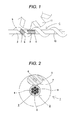
- Fig. 1 is a partial front view schematically illustrating the rope with spiral teeth according to the first embodiment of the present invention in use.
- Fig. 2 is a cross-sectional view of the rope with spiral teeth illustrated in Fig. 1 .
- notched (hatched) portions are illustrated to explain the configurations of a first rope 2 and a second rope 5.
- the second rope 5 has an elliptical cross section. This is because the second rope having a substantially circular cross section is spirally wound around the outer circumferential surface of the first rope.
- the rope with spiral teeth 1 of the first embodiment of the present invention illustrated in Figs. 1 and 2 includes the first rope 2 and the second rope 5.
- the first rope 2 includes a first core material 3 and a first resin 4 covering the first core material 3.
- the second rope 5 includes a second core material 6 and a second resin 7 covering the second core material 6.
- the second rope 5 is spirally wound around the outer circumferential surface of the first rope 2.
- At least one of the first resin 4 and the second resin 7 contains an infrared reflectance adjusting material to make their temperature rise characteristics different from each other.
- the first rope 2 and the second rope 5 are bonded together.
- the first rope 2 and the second rope 5 are bonded together without using any adhesive. In production, therefore, hardly any problem, such as uneven coating of an adhesive, will occur. This makes the bonding strength between the first rope 2 and the second rope 5 high.
- the infrared reflectance adjusting material is blended into at least one of the resins such that the temperature rise characteristics of the first resin 4 and the second resin 7 differ from each other. Therefore, the first resin 4 and the second resin 7 have different temperature rise characteristics, and in manufacturing process one resin having the higher temperature rise characteristic can be melted preferentially over the other resin having the lower temperature rise characteristic. As a result, the first rope 2 and the second rope 5 can be bonded together.
- the first resin 4 and the second resin 7 may be heated to a comparatively low temperature at which one resin having the higher temperature rise characteristic is melted in a large amount while the other resin having the lower temperature rise characteristic is only slightly melted. That is, both the first resin 4 and the second resin 7 do not need to be heated to the temperature at which both of the resins are melted in large amounts.
- the resin melted in a large amount fully bonds the first rope 2 and the second rope 5 together. Therefore, in the manufactured rope with spiral teeth 1, the thermal deformation of the first resin 4 and the second resin 7 in the bonding process is suppressed within an extent necessary for bonding. As illustrated in Figs.
- the outer shapes of the first rope 2 and the second rope 5 can be kept in predetermined shapes. That is, the protrusion having the predetermined shape is formed by the second rope 5 being spirally wound around the outer circumferential surface of the first rope 2. This protrusion can securely engage with a groove of a gear H. As a result, the driving force of a motor or the like can be reliably transmitted to the rope with spiral teeth 1 via the engaged portion. Therefore, the rope with spiral teeth 1 of the first embodiment of the present invention has less tooth jumping than the rope in the related art.
- the first resin 4 and the second resin 7 in the rope with spiral teeth 1 of the first embodiment of the present invention are thermally less deteriorated than in the rope in the related art. Therefore, the rope with spiral teeth 1 has excellent durability.
- the configuration of the first rope 2 will be described below in detail.
- the first rope 2 is in the shape of a rod with a circular cross section.
- the first core material 3 is a wire rope with a multiple-twist structure having 7 x 7 strands. That is, the first core material 3 includes a core strand 9 which is formed by twisting seven lines, and six side strands 8 which are each formed by twisting seven lines. More specifically, the first core material 3 is a wire rope in which the six side strands 8 are wound in a twisted manner around the outer circumferential surface of the single core strand 9.
- the number of lines constituting the core strand 9 or each of the side strands 8 is not limited to seven. For example, the number of lines may each be in the range of 2 to 12.
- the number of the side strands 8 around the single core strand 9 is not limited to six, and may be in the range of 2 to 12, for example.
- Examples of the material for the lines constituting the first core material 3 include, but are not limited to, stainless steel, super elastic alloy (e.g., Ni-Ti alloy), and tungsten.
- Examples of the stainless steel include, but are not limited to, maitensite-based stainless steel, ferrite-based stainless steel, austenite-based stainless steel, austenitic-ferritic duplex stainless steel, and precipitation-hardened stainless steel. Among these, the stainless steel is preferable, and austenite-based stainless steel is more preferable.
- the first resin 4 covers the outer circumferential surface of the first core material 3 with a substantially uniform thickness.
- the material forming the first resin 4 is preferably a thermoplastic resin.
- a more preferable material for the first resin 4 is at least one resin material selected from the group consisting of a polyester resin, a polyamide resin, a polyurethane resin, a fluorine resin such as a TEFLON® (registered trademark) resin, and a polyolefin resin.
- a further preferable material for the first resin 4 is at least one resin material selected from the group consisting of a polyester elastomer, a polyamide elastomer, and a polyurethane elastomer.
- the second rope 5 is in the shape of a rod with a circular cross section.
- the second rope 5 has substantially the same diameter as the first rope 2. Note that the diameters of the second rope and the first rope may be different from each other.
- the second core material 6 is formed of a single line. Note that, like the first core material, the second core material may be formed by twisting a plurality of single lines.
- the line or lines constituting the second core material 6 may be formed of the same material as the first core material 3 described above.
- the second resin 7 covers the outer circumferential surface of the second core material 6 with a substantially uniform thickness.
- the second resin 7 may be formed of the same material as the first resin 4.
- the first resin 4 and the second resin 7 are preferably formed of the same kind of resin material.
- different amounts of the infrared reflectance adjusting material are blended into the respective resins to be prepared.
- the first resin and the second resin have different temperature rise characteristics. In the bonding process, therefore, the resin having the higher temperature rise characteristic is melted first. That is, almost only one of the first resin and the second resin is melted at a time. Therefore, this type of melting causes the first rope and the second rope to be bonded together.
- the second rope 5 is spirally wound around the outer circumferential surface of the first rope 2 at a predetermined pitch.
- the pitch in this case is not particularly limited, as long as the second rope 5 engages with the gear H.
- the first resin 4 contains an infrared reflectance adjusting material A as the infrared reflectance adjusting material.
- the second resin 7 contains an infrared reflectance adjusting material B as the infrared reflectance adjusting material.
- the infrared reflectance of the infrared reflectance adjusting material A is different from that of the infrared reflectance adjusting material B. More specifically, the infrared reflectance of the infrared reflectance adjusting material B is higher than that of the infrared reflectance adjusting material A. Therefore, the temperature rise characteristic of the first resin 4 is higher than that of the second resin 7. In other words, when heat is externally applied uniformly, the first resin 4 is more easily heated and melted than the second resin 7.
- Examples of the infrared reflectance adjusting material described above include, but are not limited to, white or chromatic pigments such as a composite oxide pigment, a titanium oxide pigment, a carbon black pigment, an iron oxide-based pigment, a calcination pigment, a metal powder pigment, and an extender pigment; infrared absorbing dyes such as a polymethylene-based dye, an azulenium-based dye, a squarylium-based dye, a thiopyrylium-based dye, an anthraquinone-based dye, a phthalocyanine-based dye, an azo-based dye, and a thioamide-based dye; and infrared reflecting dyes such as a phthalocyanine-based dye, an azo-based dye, an azomethine-based dye, an anthraquinone-based dye, a perinone-perylene-based dye, an indigo-thioindigo-based dye, a dioxazin
- the infrared reflectance adjusting material may be used independently or in combination of two or more.
- the infrared reflectance adjusting material more preferably contains at least one pigment selected from the group consisting of the composite oxide pigment, the titanium oxide pigment, and the carbon black pigment.
- any infrared reflectance adjusting material A and any infrared reflectance adjusting material B may be selected from the infrared reflectance adjusting materials listed above as long as the infrared reflectance of the infrared reflectance adjusting material B is higher than that of the infrared reflectance adjusting material A.
- the carbon black pigment may be selected as the infrared reflectance adjusting material A and the titanium oxide pigment may be selected as the infrared reflectance adjusting material B.
- the titanium oxide pigment may be selected as the infrared reflectance adjusting material A
- the composite oxide pigment may be selected as the infrared reflectance adjusting material B.
- the direction of twisting the side strand 8 in the first rope 2 relative to a central axis 10 of the rope with spiral teeth 1 is preferably opposite to the direction of winding the second rope 5 around the first rope 2.
- a first rope and a second rope are prepared.
- the first rope includes a first core material and a first resin covering the first core material.
- the second rope includes a second core material and a second resin covering the second core material.
- the first resin is prepared from a resin material containing an infrared reflectance adjusting material A.
- the second resin is prepared from a resin material containing an infrared reflectance adjusting material B.
- the infrared reflectance of the infrared reflectance adjusting material A is lower than that of the infrared reflectance adjusting material B.
- the second rope is spirally wound around the outer circumferential surface of the first rope at a predetermined pitch.
- the bonding process is performed at a temperature at which the first resin or the second resin having the higher temperature rise characteristic is preferentially melted. More specifically, the bonding process can be performed at a temperature at which the first resin is easily heated and melted in a large amount.
- the bonding process is performed, for example, as follows. That is, the first rope and the second rope are passed through an atmosphere of a predetermined temperature (heating furnace). Alternatively, portions of contact between the first rope and the second rope may be irradiated with infrared rays. Through the above steps (1) and (2), the rope with spiral teeth of the present embodiment can be manufactured.
- the rope with spiral teeth of the present embodiment having the above configuration has, for example, at least the following functions and effects.
- a first rope having a circular cross section was prepared by coating a wire rope core material with a polyester elastomer (Hytrel (registered trademark) 5577 manufactured by DU PONT-TORAY CO., LTD.) as a first resin in a thickness of 0.075 mm.
- the core material is a stainless steel core material of 0.45 mm in diameter formed of a multiple-twist structure of 7 x 7 strands
- a second rope having a circular cross section was separately prepared by coating a stainless-steel core material of 0.17 mm in diameter with the polyester elastomer as a second resin in a thickness of 0.215 mm.
- infrared reflectance adjusting material A 1.5 wt% titanium oxide powders were blended in advance into the first resin (polyester elastomer) of the first rope.
- infrared reflectance adjusting material B 1.5 wt% composite oxide pigment (AG235 manufactured by KAWAMURA CHEMICAL CO., LTD.) was blended in advance into the second resin (polyester elastomer) of the second rope. That is, two different infrared reflectance adjusting materials were used, such that the infrared reflectance properties of the two resins were different.
- the second rope was spirally wound around the outer circumferential surface of the first rope at a pitch of 3.048 mm.
- a rope with spiral teeth was manufactured in the same manner as in Example 1 except that an infrared reflectance adjusting material was not blended into the polyester elastomers of the first rope and the second rope.
- a rope with spiral teeth was manufactured in the same manner as in Example 1 except that 1.5 wt% carbon black powders were blended into the respective polyester elastomers of the first rope and the second rope. That is, the same infrared reflectance adjusting material was used, such that the infrared reflectance properties of the two resins were the same.
- the rope with spiral teeth of Example 1 having resins with different reflectance properties was cut in the direction perpendicular to the longitudinal direction. The cut surface of the rope was then observed. As a result, it was confirmed that the polyester elastomer of the first rope and the polyester elastomer of the second rope were sufficiently mixed at the bonding portions. In other words, it was confirmed that the first rope and the second rope were securely bonded together. The second rope was hardly deformed, and the shape of the spiral protrusion formed of the second rope was well maintained. Therefore, when the rope with spiral teeth of Example 1 is engaged with a gear, it seems that the second rope securely may engage with a groove of the gear, and that the tooth jumping hardly may occur.
- first rope and the second rope were fully bonded together by the short-time bonding process performed at a relatively low bonding temperature.
- the thermal deterioration of the polyester elastomer was suppressed to a low level, and it seems that excellent durability may be imparted to the rope with spiral teeth of Example 1.
- the polyester elastomer of the first rope and the polyester elastomer of the second rope are not fully mixed at the bonding portions, compared to the rope with spiral teeth of Example 1 manufactured under the same conditions of the bonding process (410°C for 24 seconds). Therefore, the degree of bonding between the first rope and the second rope is low.
- an increase in the bonding temperature or time for the bonding process may be required. In that case, however, it is believed that the thermal deterioration of the polyester elastomer is more likely to occur and that the durability of the polyester elastomer is lowered.
- the bonding process is performed under the conditions that the second resin is easily heated originally.
- the infrared reflectance adjusting material is preferably blended into each of the first resin and the second resin such that the temperature rise characteristic of the first resin is higher than that of the second resin.
- the infrared reflectance adjusting material may be blended such that the temperature rise characteristic of the second resin is higher than that of the first resin when the bonding process is performed under the conditions that the first resin positioned inside is easily heated originally.
- the infrared reflectance adjusting material may be blended only into the first resin such that the temperature rise characteristic of the first resin and that of the second resin are different from each other. Further alternatively, the infrared reflectance adjusting material may be blended only into the second resin.
- the functions and effects of the present invention can advantageously be obtained.
- the rope with spiral teeth of the present invention may be manufactured by the following production method, for example. That is, a method for manufacturing a rope with spiral teeth of the present invention includes: a winding step of manufacturing a rope precursor by spirally winding a second rope around the outer circumferential surface of a first rope, the first rope being obtained by coating a first core material with a first resin, the second rope being obtained by coating a second core material with a second resin; and a bonding step of performing a bonding process by heating the rope precursor.
- an infrared reflectance adjusting material is blended into at least one of the first resin and the second resin such that the temperature rise characteristic of the first resin differs from that of the second resin.
- the temperature at the time of the bonding process in the bonding step is one at which the first resin or the second resin, whichever has the higher temperature rise characteristic, is melted.
Landscapes
- Engineering & Computer Science (AREA)
- General Engineering & Computer Science (AREA)
- Mechanical Engineering (AREA)
- Ropes Or Cables (AREA)
- Gears, Cams (AREA)
Applications Claiming Priority (1)
| Application Number | Priority Date | Filing Date | Title |
|---|---|---|---|
| JP2011115936A JP2012241881A (ja) | 2011-05-24 | 2011-05-24 | 螺旋状歯付きロープ |
Publications (2)
| Publication Number | Publication Date |
|---|---|
| EP2527684A2 true EP2527684A2 (de) | 2012-11-28 |
| EP2527684A3 EP2527684A3 (de) | 2013-11-20 |
Family
ID=45977231
Family Applications (1)
| Application Number | Title | Priority Date | Filing Date |
|---|---|---|---|
| EP12163386.1A Withdrawn EP2527684A3 (de) | 2011-05-24 | 2012-04-05 | Seil mit Spiralenzähnen |
Country Status (4)
| Country | Link |
|---|---|
| US (1) | US20120297747A1 (de) |
| EP (1) | EP2527684A3 (de) |
| JP (1) | JP2012241881A (de) |
| CN (1) | CN102797791A (de) |
Cited By (1)
| Publication number | Priority date | Publication date | Assignee | Title |
|---|---|---|---|---|
| EP2447567B1 (de) * | 2010-10-28 | 2016-10-12 | Asahi Intecc Co., Ltd. | Schraubenförmig gezahntes Seil |
Families Citing this family (1)
| Publication number | Priority date | Publication date | Assignee | Title |
|---|---|---|---|---|
| WO2024141999A1 (en) * | 2022-12-28 | 2024-07-04 | Harrigan Scott | Glow in the dark and infrared reflective article |
Citations (2)
| Publication number | Priority date | Publication date | Assignee | Title |
|---|---|---|---|---|
| JP2001241514A (ja) | 2000-02-25 | 2001-09-07 | Asahi Intecc Co Ltd | 螺旋状歯付きロープと、その成形方法 |
| JP2004239347A (ja) | 2003-02-06 | 2004-08-26 | Asahi Intecc Co Ltd | 螺旋状歯付きロープ |
Family Cites Families (4)
| Publication number | Priority date | Publication date | Assignee | Title |
|---|---|---|---|---|
| JPS4431312Y1 (de) * | 1965-09-14 | 1969-12-24 | ||
| JP3472213B2 (ja) * | 1999-11-10 | 2003-12-02 | ペンタックス株式会社 | 内視鏡の操作ワイヤ駆動機構 |
| CN101115683B (zh) * | 2005-02-10 | 2011-10-26 | 户田工业株式会社 | 红外线反射用黑色颜料、涂料和树脂组合物 |
| NZ592948A (en) * | 2008-11-20 | 2013-04-26 | Nexans | An electrical cable with infrared radiation reflection layer using metal oxides |
-
2011
- 2011-05-24 JP JP2011115936A patent/JP2012241881A/ja active Pending
-
2012
- 2012-04-05 EP EP12163386.1A patent/EP2527684A3/de not_active Withdrawn
- 2012-04-09 CN CN201210102424XA patent/CN102797791A/zh active Pending
- 2012-04-12 US US13/445,465 patent/US20120297747A1/en not_active Abandoned
Patent Citations (2)
| Publication number | Priority date | Publication date | Assignee | Title |
|---|---|---|---|---|
| JP2001241514A (ja) | 2000-02-25 | 2001-09-07 | Asahi Intecc Co Ltd | 螺旋状歯付きロープと、その成形方法 |
| JP2004239347A (ja) | 2003-02-06 | 2004-08-26 | Asahi Intecc Co Ltd | 螺旋状歯付きロープ |
Cited By (1)
| Publication number | Priority date | Publication date | Assignee | Title |
|---|---|---|---|---|
| EP2447567B1 (de) * | 2010-10-28 | 2016-10-12 | Asahi Intecc Co., Ltd. | Schraubenförmig gezahntes Seil |
Also Published As
| Publication number | Publication date |
|---|---|
| EP2527684A3 (de) | 2013-11-20 |
| US20120297747A1 (en) | 2012-11-29 |
| CN102797791A (zh) | 2012-11-28 |
| JP2012241881A (ja) | 2012-12-10 |
Similar Documents
| Publication | Publication Date | Title |
|---|---|---|
| EP2407592A2 (de) | Aufzugsdrahtseil | |
| KR101112502B1 (ko) | 피복 와이어 로프 | |
| KR100740493B1 (ko) | 피복형 와이어 로프 | |
| EP2527684A2 (de) | Seil mit Spiralenzähnen | |
| US20220379096A1 (en) | Guide wire | |
| KR20140019958A (ko) | 내굴곡성이 우수한 열선 케이블 | |
| JP5938163B2 (ja) | 高屈曲絶縁電線 | |
| US20170328000A1 (en) | Wire rope | |
| CN115933079B (zh) | 一种无扎纱自啮合层绞式光缆及其制造方法 | |
| JP5625604B2 (ja) | ゴム補強用スチールコード | |
| US20050160714A1 (en) | Synthetic cord for tennis racket | |
| DE102007041233B4 (de) | Steigungskabel mit Flockfaden | |
| EP2781771A1 (de) | Biegsame Welle mit Presspassungsfähigkeit | |
| KR20180065965A (ko) | 다층체, 다층 중공체 및 다층 중공체를 구비한 카테터 | |
| JP7574002B2 (ja) | コイル体 | |
| JP2011202321A (ja) | 環状金属コード、無端金属ベルト及び環状金属コードの製造方法 | |
| WO1995004357A1 (en) | Improved dielectric miniature electric cable | |
| JP7537911B2 (ja) | 難燃性に優れた高屈曲ヒータ線及び発熱体 | |
| EP1992723A1 (de) | Garn und herstellungsverfahren dafür | |
| CN101175879A (zh) | 三层的成束拉制金属纤维 | |
| CN112166027A (zh) | 正齿轮部件、正齿轮和正齿轮部件的制造方法 | |
| EP2500465A1 (de) | Drahtseil mit Füller | |
| JP5105644B2 (ja) | 螺旋状歯付きロープ | |
| JP7721497B2 (ja) | 操作用ロープ | |
| JP2010249310A (ja) | 伝動ベルト及びその製造方法 |
Legal Events
| Date | Code | Title | Description |
|---|---|---|---|
| PUAI | Public reference made under article 153(3) epc to a published international application that has entered the european phase |
Free format text: ORIGINAL CODE: 0009012 |
|
| AK | Designated contracting states |
Kind code of ref document: A2 Designated state(s): AL AT BE BG CH CY CZ DE DK EE ES FI FR GB GR HR HU IE IS IT LI LT LU LV MC MK MT NL NO PL PT RO RS SE SI SK SM TR |
|
| AX | Request for extension of the european patent |
Extension state: BA ME |
|
| PUAL | Search report despatched |
Free format text: ORIGINAL CODE: 0009013 |
|
| AK | Designated contracting states |
Kind code of ref document: A3 Designated state(s): AL AT BE BG CH CY CZ DE DK EE ES FI FR GB GR HR HU IE IS IT LI LT LU LV MC MK MT NL NO PL PT RO RS SE SI SK SM TR |
|
| AX | Request for extension of the european patent |
Extension state: BA ME |
|
| RIC1 | Information provided on ipc code assigned before grant |
Ipc: F16G 9/00 20060101AFI20131015BHEP Ipc: D07B 5/00 20060101ALN20131015BHEP |
|
| STAA | Information on the status of an ep patent application or granted ep patent |
Free format text: STATUS: THE APPLICATION IS DEEMED TO BE WITHDRAWN |
|
| 18D | Application deemed to be withdrawn |
Effective date: 20140521 |