EP2527166A1 - Bead breaking unit for tyre changing machines - Google Patents
Bead breaking unit for tyre changing machines Download PDFInfo
- Publication number
- EP2527166A1 EP2527166A1 EP12167805A EP12167805A EP2527166A1 EP 2527166 A1 EP2527166 A1 EP 2527166A1 EP 12167805 A EP12167805 A EP 12167805A EP 12167805 A EP12167805 A EP 12167805A EP 2527166 A1 EP2527166 A1 EP 2527166A1
- Authority
- EP
- European Patent Office
- Prior art keywords
- bead breaking
- arm
- breaking unit
- reference element
- movement
- Prior art date
- Legal status (The legal status is an assumption and is not a legal conclusion. Google has not performed a legal analysis and makes no representation as to the accuracy of the status listed.)
- Granted
Links
Images


Classifications
-
- B—PERFORMING OPERATIONS; TRANSPORTING
- B60—VEHICLES IN GENERAL
- B60C—VEHICLE TYRES; TYRE INFLATION; TYRE CHANGING; CONNECTING VALVES TO INFLATABLE ELASTIC BODIES IN GENERAL; DEVICES OR ARRANGEMENTS RELATED TO TYRES
- B60C25/00—Apparatus or tools adapted for mounting, removing or inspecting tyres
- B60C25/01—Apparatus or tools adapted for mounting, removing or inspecting tyres for removing tyres from or mounting tyres on wheels
- B60C25/05—Machines
- B60C25/125—Machines for only breaking the beads
- B60C25/13—Machines for only breaking the beads acting axially on a part of the bead or side wall only at localised regions of the bead or side wall
Definitions
- the present invention relates to an upgraded bead breaking unit for tyre changing machines or the like.
- Tyre changing machines are commonly used for fitting/removing vehicle wheel tyres to/from respective rims.
- This operation is performed by means of a suitable bead breaking unit, normally present on the tyre changing machine itself.
- Bead breaking units of known type comprise an arm with a first extremity hinged to the bed of the tyre changing machine according to a substantially vertical axis and a second extremity having a bead breaking tool, otherwise known as blade.
- This supporting element has a supporting surface, otherwise known as pad, which is made of suitable material, and usually knurled in such a way as to increase the friction coefficient with the wheel.
- the bead breaking units of known type generally comprise a linear actuator of the type, e.g., of a fluid actuator cylinder for moving the arm.
- the liner of the actuator cylinder is hinged to the bed and can be rotated around a vertical axis, while the stem is moving between an extracted position and a retracted position and is associated sliding with the arm.
- the stem has a driving element which, during movement from the extracted position to the retracted position, is suitable for engaging on the arm to drive it to the bed.
- the stem of the cylinder is normally extracted and the arm, which can be freely rotated around its hinging axis, is in a closer position with respect to the bed of the tyre changing machine due to the action of one return spring.
- the stem of the actuator cylinder is moved to extracted position and the operator manually extracts the blade inserted between tyre and rim.
- the arm is again moved to near position with respect to the bed of the tyre changing machine due to the action of the return spring.
- the known bead breaking units do however have a number of drawbacks.
- EP20100194050 describes a bead breaking unit able to overcome such drawbacks which is able to automatically remove the blade inserted between the tyre and the rim after bead breaking.
- the stem of the actuator has a thrust element which is suitable for engaging on a respective reference element on the arm during the movement of the stem itself from the retracted position to the extracted position so as to move the blade away from the wheel.
- this known bead breaking unit is susceptible to upgrading, aimed in particular at permitting greater operating versatility depending on the type of tyre to undergo bead breaking, the size of the tyre itself and/or the particular requirements of the operator using the unit.
- the main aim of the present invention is to provide an upgraded bead breaking unit for tyre changing machines or the like that allows minimizing manual jobs by the operators during the bead breaking operation, and, at the same time, permit a versatile use depending on the type of tyre to undergo bead breaking, the size of the tyre itself and/or the particular requirements of the operator using the unit.
- Another object of the present invention is to provide an upgraded bead breaking unit for tyre changing machines or the like which allows overcoming the mentioned drawbacks of the state of the art within the ambit of a simple, rational, easy and effective to use as well as low cost solution.
- the present upgraded bead breaking unit for tyre changing machines or the like, comprising an arm having a bead breaking tool and associated rotatable with a supporting structure between an away position, wherein said bead breaking tool is substantially spaced out from said supporting structure, and a work position, wherein said bead breaking tool is substantially placed near said supporting structure, actuator means having at least a mobile element associated sliding with said arm, dragging means for dragging said arm, associated with said mobile element and suitable for operating during the movement of said mobile element from an extracted position to a retracted position to bring said arm to said work position and temporary coupling means between said mobile element and said arm, suitable for operating during the movement of said mobile element from said retracted position to said extracted position to bring said arm from said work position to said away position, characterised in that it comprises selection means associated with said temporary coupling means and suitable for operating/disconnecting said temporary coupling means.
- a bead breaking unit which can be fitted on a tyre changing machine of known type and usable for the first detachment of the bead of the tyre from the respective rim of a wheel, before the fitting/removing operation of the tyre itself.
- the bead breaking unit 1 comprises an arm 2 with a first extremity 2a hinged to a supporting structure 3 and rotatable around a substantially vertical hinging axis, and a second extremity 2b having a bead breaking tool 4 of the type, e.g., of a conventional blade or the like.
- the supporting structure 3 can be made up, e.g., of the bed of a traditional tyre changing machine M.
- the arm 2 is suitable for swinging between an away position, wherein the bead breaking tool 4 is substantially spaced out from the supporting element 5, and a work position, wherein the bead breaking tool 4 is placed substantially near the supporting element 5 and is suitable for pressing on the tyre of a wheel R to undergo bead breaking.
- Elastic return means are placed between the supporting structure 3 and the arm 2 and operate to bring back the arm 2 from the away position to the work position.
- the bead breaking unit 1 also comprises actuator means 6 having a mobile element 7 associated sliding with the arm 2 and moving between an extracted position and a retracted position.
- the actuator means 6 are composed of a linear actuator, of the type of a fluid actuator cylinder or the like.
- the linear actuator 6 has a fixed portion 8, made up of the liner of the linear actuator itself, hinged to the supporting structure 3 and rotatable around a substantially vertical axis.
- the mobile element 7 is made up of the mobile stem of the linear actuator 6.
- the stem 7, in particular, is sustained axially sliding by sliding supporting means on the arm 2, schematically shown in the illustrations and indicated with the reference 9, and is moving between the retracted position, wherein it is partially housed inside the liner 8, and the extracted position, wherein it is completely extended from the liner 8.
- the stem 7 has dragging means 10 of the arm 2, suitable for operating during the movement of the stem itself from the extracted position to the retracted position to move the arm 2 to the work position.
- the dragging means 10 are made up of a head with a substantially widened shape fastened to the free extremity of the stem 7 and suitable for engaging onto the sliding supporting means 9 during the movement of the stem itself from the extracted position to the retracted position.
- the bead breaking unit 1 comprises temporary coupling means between the stem 7 and the arm 2, suitable for operating during the movement of the stem itself from the retracted position to the extracted position.
- the temporary coupling means allow using the stem 7, during the movement from the retracted position to the extracted position, to move the arm 2 from the work position to the away position.
- the bead breaking unit 1 comprises selection means, generally indicated in the illustrations by the reference 11, associated with the temporary coupling means suitable for operating ( figure 2 ) and disconnecting ( figure 3 ) the temporary coupling means themselves.
- the presence of the selection means 11, in particular, allows the versatile use of the bead breaking unit 1, permitting to operate or disconnect the above temporary coupling means depending on the type of tyre of the wheel R to undergo bead breaking, the size of the tyre itself and/or the particular requirements of the operator using the bead breaking unit 1.
- the temporary coupling means comprise a thrust element 10 associated integral with the stem 7 and a reference element 12 associated with the arm 2.
- the thrust element 10 is suitable for engaging on the reference element 12 during the movement of the stem 7 from the retracted position to the extracted position.
- the thrust element 10 is made up of the same head used to drive the arm 2 to the work position.
- the reference element 12 is moving between an operating position, wherein it is arranged along the trajectory of the head 10, and a disengagement position, wherein it is substantially away from the trajectory of the head 10.
- the above temporary coupling means also comprise contrast elastic means 13, of the type of a thrust spring or the like, suitable for contrasting the movement of the reference element 12 from the operating position to the disengagement position.
- the temporary coupling means comprise guide means for guiding the reference element 12 suitable for guiding the movement of the reference element itself between the operating position and the disengagement position.
- the guide means of the reference element 12 comprise a sliding element 14, supporting the reference element 12, associated sliding with a straight guide element 15 fixed to the arm 2.
- the sliding element 14 is made up of a pin having at one extremity the reference element 12.
- the straight guide element 15 is made up of a tubular support fastened to the arm 2 and having a seat that houses the pin 14 axially sliding.
- the thrust spring 13 is fitted inside the seat of the tubular support 15, around the pin 14, and operates to move the reference element 12 to the operating position.
- the reference element 12 has a first contact surface 12a which, when the arm 2 is in work position, is substantially at right angles with respect to the trajectory of the head 10.
- the first contact surface 12a is suitable for being engaged by the head 10 during the movement of the stem 7 from the retracted position to the extracted position, -to move the arm 2 from the work position to the away position.
- the reference element 12 also comprises a second contact surface 12b which, when the arm 2 is in work position, is substantially inclined with respect to the trajectory of the head 10.
- the second contact surface 12b is suitable for being engaged by the head 10 during the movement of the stem 7 from the extracted position to the retracted position, for the movement of the reference element 12 from the operating position to the disengagement position.
- the first contact surface 12a and the second contact surface 12b are defined on faces of the reference element 12 substantially opposite one another.
- the selection means 11 are made up of locking means for locking the reference element 12 in a disengagement position ( figure 3 ).
- the locking means 11 comprise a retention element 16 associated integral with the reference element 12 and moving between:
- the temporary coupling means between the stem 7 and the arm 2 operate during the movement of the stem itself from the retracted position to the extracted position, allowing the use of the stem 7 for the movement of the arm 2 from the work position to the away position.
- the locking means 11 also comprise guide means 17 for guiding the retention element 16 between the above operating and disconnection positions.
- the guide means 17 for guiding the retention element 16 are made up of a slot obtained on the arm 2 and having:
- the retention element 16 is retained in the disengagement position by the edge of the second section 17b of the slot 17.
- the slot 17 is obtained on a plate 2c of the arm 2.
- the plate 2c supports the tubular support 15 of the same temporary coupling means.
- the retention element 16 is made up of a control lever which is fitted sliding inside the slot 17 and which extends at least in part from the slot itself to the outside of the arm 2.
- the slot 17 is preferably shaped like an overturned L, with the first section 17a and the second section 17b straight and at right angles to one another.
- control lever 16 is fixed to the extremity of the sliding element 14 opposite the extremity which supports the reference element 12.
- the operator uses the selection means 11 to operate and disconnect the temporary coupling means between the arm 2 and the stem 7.
- the action of the thrust spring 13, therefore, returns the reference element 12 from the disengagement position to the work position ( figure 2 ).
- the stem of the linear actuator is in the extracted position and, in such configuration, the arm is free to rotate around its hinging axis ( figure 4 ).
- the head 10 moves into contact with the reference element 12 and engages on the second contact surface 12b, moving the reference element itself from the operating position to the disengagement position ( figure 6 ).
- the head 10 engages on the sliding supporting means 9, driving the arm 2 to the work position.
- the bead breaker tool 4 presses on the tyre of the wheel R, until the bead is moved away from the edge of the rim ( figure 7 ).
- the stem 7 is then moved from the retracted position to the extracted position and, during such movement, the head 10 engages on the first contact surface 12a of the reference element 12.
- the temporary coupling means between the stem of the linear actuator and the arm and the selection means suitable for operating/disconnecting such temporary coupling means allow minimizing manual jobs by the operators during bead breaking and, at the same time, permit a versatile use of the bead breaking unit depending on the type of tyre to undergo bead breaking, the size of the tyre itself and/or the particular requirements of the operator using the machine.
Landscapes
- Engineering & Computer Science (AREA)
- Mechanical Engineering (AREA)
- Tires In General (AREA)
- Tyre Moulding (AREA)
- Compositions Of Macromolecular Compounds (AREA)
- Graft Or Block Polymers (AREA)
- Organic Low-Molecular-Weight Compounds And Preparation Thereof (AREA)
Abstract
Description
- The present invention relates to an upgraded bead breaking unit for tyre changing machines or the like.
- Tyre changing machines are commonly used for fitting/removing vehicle wheel tyres to/from respective rims.
- As is known, before being able to completely remove a tyre from its housing on the respective rim, it is necessary to detach the beads thereof from the bead retention edges on the rim itself.
- This operation is performed by means of a suitable bead breaking unit, normally present on the tyre changing machine itself.
- Bead breaking units of known type comprise an arm with a first extremity hinged to the bed of the tyre changing machine according to a substantially vertical axis and a second extremity having a bead breaking tool, otherwise known as blade.
- On the bed is fastened a supporting element, usable to correctly fit the rim during the bead breaking operation.
- This supporting element has a supporting surface, otherwise known as pad, which is made of suitable material, and usually knurled in such a way as to increase the friction coefficient with the wheel.
- The bead breaking units of known type generally comprise a linear actuator of the type, e.g., of a fluid actuator cylinder for moving the arm.
- The liner of the actuator cylinder is hinged to the bed and can be rotated around a vertical axis, while the stem is moving between an extracted position and a retracted position and is associated sliding with the arm.
- The stem has a driving element which, during movement from the extracted position to the retracted position, is suitable for engaging on the arm to drive it to the bed.
- During use, in an idle position of the bead breaking unit, the stem of the cylinder is normally extracted and the arm, which can be freely rotated around its hinging axis, is in a closer position with respect to the bed of the tyre changing machine due to the action of one return spring.
- An operator, once the portion of the wheel to undergo bead breaking has been suitably positioned in correspondence to the pad, manually moves the arm until the blade is positioned in contact with a section of the tyre bead.
- Subsequently, the operator starts the actuator cylinder, moving the stem from the extracted position to the retracted position.
- This way, the arm is driven by the stem and the blade pushes the tyre bead, detaching it from the edge of the rim.
- Subsequently, the stem of the actuator cylinder is moved to extracted position and the operator manually extracts the blade inserted between tyre and rim. Once the wheel has been removed, the arm is again moved to near position with respect to the bed of the tyre changing machine due to the action of the return spring.
- The known bead breaking units do however have a number of drawbacks.
- In particular, after bead breaking, the extraction operation of the blade inserted between the tyre and the rim must be performed manually by the operator.
- This requires a far from negligible physical effort by the operator, particularly for large wheels, an effort which must often be repeated several times during the course of a day.
- Furthermore, in the frequent case of the blade remaining trapped between the tyre bead and the edge of the rim, the job becomes necessary of more than one operator, with the consequent and onerous use of time and personnel.
- The document no.
EP20100194050 - In this bead breaking unit, in particular, the stem of the actuator has a thrust element which is suitable for engaging on a respective reference element on the arm during the movement of the stem itself from the retracted position to the extracted position so as to move the blade away from the wheel.
- Also this known bead breaking unit, nevertheless, is susceptible to upgrading, aimed in particular at permitting greater operating versatility depending on the type of tyre to undergo bead breaking, the size of the tyre itself and/or the particular requirements of the operator using the unit.
- The main aim of the present invention is to provide an upgraded bead breaking unit for tyre changing machines or the like that allows minimizing manual jobs by the operators during the bead breaking operation, and, at the same time, permit a versatile use depending on the type of tyre to undergo bead breaking, the size of the tyre itself and/or the particular requirements of the operator using the unit.
- Another object of the present invention is to provide an upgraded bead breaking unit for tyre changing machines or the like which allows overcoming the mentioned drawbacks of the state of the art within the ambit of a simple, rational, easy and effective to use as well as low cost solution.
- The above objects are achieved by the present upgraded bead breaking unit for tyre changing machines or the like, comprising an arm having a bead breaking tool and associated rotatable with a supporting structure between an away position, wherein said bead breaking tool is substantially spaced out from said supporting structure, and a work position, wherein said bead breaking tool is substantially placed near said supporting structure, actuator means having at least a mobile element associated sliding with said arm, dragging means for dragging said arm, associated with said mobile element and suitable for operating during the movement of said mobile element from an extracted position to a retracted position to bring said arm to said work position and temporary coupling means between said mobile element and said arm, suitable for operating during the movement of said mobile element from said retracted position to said extracted position to bring said arm from said work position to said away position, characterised in that it comprises selection means associated with said temporary coupling means and suitable for operating/disconnecting said temporary coupling means.
- Other characteristics and advantages of the present invention will become more evident from the description of a preferred, but not sole, embodiment of an upgraded bead breaking unit for tyre changing machines or the like, illustrated purely as an example but not limited to the annexed drawings in which:
-
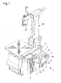
Figure 1 is an axonometric view of the bead breaking unit according to the invention fitted on a traditional tyre changing machine; -
Figure 2 shows a detail of the bead breaking unit according to the invention with the selection means arranged for operating the temporary coupling means; -
Figure 3 shows a detail of the bead breaking unit according to the invention with the selection means arranged for disconnecting the temporary coupling means; - Figures from 4 to 9 are plan views which show the operation of the bead breaking unit according to the invention with the temporary coupling means in the operating configuration.
- With particular reference to such figures, globally indicated by 1 is a bead breaking unit which can be fitted on a tyre changing machine of known type and usable for the first detachment of the bead of the tyre from the respective rim of a wheel, before the fitting/removing operation of the tyre itself.
- The bead breaking
unit 1 comprises anarm 2 with afirst extremity 2a hinged to a supportingstructure 3 and rotatable around a substantially vertical hinging axis, and asecond extremity 2b having a bead breakingtool 4 of the type, e.g., of a conventional blade or the like. - The supporting
structure 3 can be made up, e.g., of the bed of a traditional tyre changing machine M. - To the supporting
structure 3 is fixed a supportingelement 5, also called pad, usable for the correct positioning of a wheel R to undergo bead breaking. - The
arm 2 is suitable for swinging between an away position, wherein the bead breakingtool 4 is substantially spaced out from the supportingelement 5, and a work position, wherein the bead breakingtool 4 is placed substantially near the supportingelement 5 and is suitable for pressing on the tyre of a wheel R to undergo bead breaking. - Elastic return means, not shown in the figures inasmuch as of known type, are placed between the supporting
structure 3 and thearm 2 and operate to bring back thearm 2 from the away position to the work position. - The bead breaking
unit 1 also comprises actuator means 6 having amobile element 7 associated sliding with thearm 2 and moving between an extracted position and a retracted position. - In particular, with non-restricted reference to the embodiment of the
bead breaking unit 1 shown in the illustrations, the actuator means 6 are composed of a linear actuator, of the type of a fluid actuator cylinder or the like. - The
linear actuator 6 has afixed portion 8, made up of the liner of the linear actuator itself, hinged to the supportingstructure 3 and rotatable around a substantially vertical axis. Themobile element 7 is made up of the mobile stem of thelinear actuator 6. - The
stem 7, in particular, is sustained axially sliding by sliding supporting means on thearm 2, schematically shown in the illustrations and indicated with thereference 9, and is moving between the retracted position, wherein it is partially housed inside theliner 8, and the extracted position, wherein it is completely extended from theliner 8. - The
stem 7 has dragging means 10 of thearm 2, suitable for operating during the movement of the stem itself from the extracted position to the retracted position to move thearm 2 to the work position. - With particular but not exclusive reference to the embodiment of the
bead breaking unit 1 shown in the illustrations, thedragging means 10 are made up of a head with a substantially widened shape fastened to the free extremity of thestem 7 and suitable for engaging onto the sliding supportingmeans 9 during the movement of the stem itself from the extracted position to the retracted position. Different embodiments of the dragging means 10 cannot however be ruled out. Advantageously, thebead breaking unit 1 comprises temporary coupling means between thestem 7 and thearm 2, suitable for operating during the movement of the stem itself from the retracted position to the extracted position. - In particular, the temporary coupling means allow using the
stem 7, during the movement from the retracted position to the extracted position, to move thearm 2 from the work position to the away position. - This allows automatically extracting the bead breaking
tool 4 which, after the bead breaking operation, is inserted between the tyre and the rim of the wheel R. - Advantageously, the
bead breaking unit 1 comprises selection means, generally indicated in the illustrations by thereference 11, associated with the temporary coupling means suitable for operating (figure 2 ) and disconnecting (figure 3 ) the temporary coupling means themselves. - The presence of the selection means 11, in particular, allows the versatile use of the
bead breaking unit 1, permitting to operate or disconnect the above temporary coupling means depending on the type of tyre of the wheel R to undergo bead breaking, the size of the tyre itself and/or the particular requirements of the operator using thebead breaking unit 1. - With particular, but not sole reference to the embodiment of the
bead breaking unit 1 shown in the illustrations, the temporary coupling means comprise athrust element 10 associated integral with thestem 7 and areference element 12 associated with thearm 2. - The
thrust element 10 is suitable for engaging on thereference element 12 during the movement of thestem 7 from the retracted position to the extracted position. - Usefully, the
thrust element 10 is made up of the same head used to drive thearm 2 to the work position. - The
reference element 12 is moving between an operating position, wherein it is arranged along the trajectory of thehead 10, and a disengagement position, wherein it is substantially away from the trajectory of thehead 10. - The above temporary coupling means also comprise contrast elastic means 13, of the type of a thrust spring or the like, suitable for contrasting the movement of the
reference element 12 from the operating position to the disengagement position. - Usefully, the temporary coupling means comprise guide means for guiding the
reference element 12 suitable for guiding the movement of the reference element itself between the operating position and the disengagement position. In particular, the guide means of thereference element 12 comprise asliding element 14, supporting thereference element 12, associated sliding with astraight guide element 15 fixed to thearm 2. - With particular reference to the embodiment shown in the illustrations, the
sliding element 14 is made up of a pin having at one extremity thereference element 12. - The
straight guide element 15 is made up of a tubular support fastened to thearm 2 and having a seat that houses thepin 14 axially sliding. - The
thrust spring 13 is fitted inside the seat of thetubular support 15, around thepin 14, and operates to move thereference element 12 to the operating position. Usefully, thereference element 12 has afirst contact surface 12a which, when thearm 2 is in work position, is substantially at right angles with respect to the trajectory of thehead 10. - The
first contact surface 12a is suitable for being engaged by thehead 10 during the movement of thestem 7 from the retracted position to the extracted position, -to move thearm 2 from the work position to the away position. - The
reference element 12 also comprises asecond contact surface 12b which, when thearm 2 is in work position, is substantially inclined with respect to the trajectory of thehead 10. - The
second contact surface 12b is suitable for being engaged by thehead 10 during the movement of thestem 7 from the extracted position to the retracted position, for the movement of thereference element 12 from the operating position to the disengagement position. - In particular, the
first contact surface 12a and thesecond contact surface 12b are defined on faces of thereference element 12 substantially opposite one another. With particular, but not sole reference to the embodiment of thebead breaking unit 1 shown in the illustrations, the selection means 11 are made up of locking means for locking thereference element 12 in a disengagement position (figure 3 ). - Usefully, the locking means 11 comprise a
retention element 16 associated integral with thereference element 12 and moving between: - an operating position, shown in the
figure 2 , wherein thereference element 12 is free to move between the above work and disengagement positions; - a disconnection position, shown in the
figure 3 , wherein thereference element 12 is locked in a disengagement position. - Consequently, when the
retention element 16 is in the operating position, the temporary coupling means between thestem 7 and thearm 2 operate during the movement of the stem itself from the retracted position to the extracted position, allowing the use of thestem 7 for the movement of thearm 2 from the work position to the away position. - On the contrary, when the
retention element 16 is in the disconnection position, thethrust element 10 on thestem 7 does not engage on thereference element 12 during the movement of the stem itself from the retracted position to the extracted position. - In this case, therefore, the movement of the
arm 2 from the work position to the away position, and therefore the extraction of theblade 4 from the wheel R, can be done manually by the operator. - The locking means 11 also comprise guide means 17 for guiding the
retention element 16 between the above operating and disconnection positions. Preferably, the guide means 17 for guiding theretention element 16 are made up of a slot obtained on thearm 2 and having: - a
first section 17a extending along a direction substantially parallel to the direction of movement of thereference element 12; - a
second section 17b extending along a direction substantially transversal to the direction of movement of thereference element 12. - In actual facts, when the
retention element 16 is in the above operating position, then it is fitted sliding inside thefirst section 17a of theslot 17. - Instead, when the
retention element 16 is in the above disconnection position, then it is fitted inside thesecond section 17b of theslot 17. - In this latter case, therefore, the
retention element 16 is retained in the disengagement position by the edge of thesecond section 17b of theslot 17. - In particular, the
slot 17 is obtained on aplate 2c of thearm 2. Theplate 2c supports thetubular support 15 of the same temporary coupling means. - In a preferred embodiment, the
retention element 16 is made up of a control lever which is fitted sliding inside theslot 17 and which extends at least in part from the slot itself to the outside of thearm 2. - Furthermore, the
slot 17 is preferably shaped like an overturned L, with thefirst section 17a and thesecond section 17b straight and at right angles to one another. - Furthermore, the
control lever 16 is fixed to the extremity of the slidingelement 14 opposite the extremity which supports thereference element 12. - The operation of the
bead breaking unit 1 is described below. - First of all, the operator uses the selection means 11 to operate and disconnect the temporary coupling means between the
arm 2 and thestem 7. - In the event of the operator deciding to stop the temporary coupling means, then he/she makes the
control lever 16 slide inside thefirst section 17a of theslot 17 until thereference element 12 shifts from the work position to the disengagement position. - Subsequently, he/she moves the
control lever 16 inside thesection 17b of the slot 17 (figure 3 ). - In this position, the
reference element 12 is completely retracted and blocked in a disengagement position and is completely ineffective as regards the operation of thebead breaking unit 1. - In the event instead of the operator deciding to operate the temporary coupling means, then he/she makes the
control lever 16 slide inside thesecond section 17b of theslot 17 until this is in correspondence with the first section. - The action of the
thrust spring 13, therefore, returns thereference element 12 from the disengagement position to the work position (figure 2 ). - The use of the
bead breaking unit 1 with the temporary coupling means in the operating configuration is described in detail below. - When the bead breaking unit is not used, the stem of the linear actuator is in the extracted position and, in such configuration, the arm is free to rotate around its hinging axis (
figure 4 ). - During use, first of all an operator positions a wheel R to undergo bead breaking in correspondence to the supporting
element 5 and manually moves thearm 2 so as to position thebead breaking tool 4 in correspondence to a section of the tyre of the wheel R (figure 5 ). - Subsequently, the operator operates the
linear actuator 6 and thestem 7 moves from the extracted position to the retracted position. - During such movement, the
head 10 moves into contact with thereference element 12 and engages on thesecond contact surface 12b, moving the reference element itself from the operating position to the disengagement position (figure 6 ). - Once the
head 10 has passed beyond thereference element 12, this is returned to the operating position by means of thethrust spring 13. - Subsequently, the
head 10 engages on the sliding supportingmeans 9, driving thearm 2 to the work position. - Consequently, the
bead breaker tool 4 presses on the tyre of the wheel R, until the bead is moved away from the edge of the rim (figure 7 ). - The
stem 7 is then moved from the retracted position to the extracted position and, during such movement, thehead 10 engages on thefirst contact surface 12a of thereference element 12. - Consequently, the
arm 2 is pushed to the away position and thebead breaking tool 4 is extracted and moved away from the wheel R (figure 8 ). - Finally, when the
stem 7 reaches the extracted position, thehead 10 passes beyond the reference element (figure 9 ) and thearm 2 is returned to the work position by means of the return elastic means (figure 4 ). - It has in point of fact been ascertained how the described invention achieves the proposed objects.
- In particular, the fact is underlined that the temporary coupling means between the stem of the linear actuator and the arm and the selection means suitable for operating/disconnecting such temporary coupling means allow minimizing manual jobs by the operators during bead breaking and, at the same time, permit a versatile use of the bead breaking unit depending on the type of tyre to undergo bead breaking, the size of the tyre itself and/or the particular requirements of the operator using the machine.
Claims (15)
- Upgraded bead breaking unit (1) for tyre changing machines or the like, comprising an arm (2) having a bead breaking tool (4) and associated rotatable with a supporting structure (3) between an away position, wherein said bead breaking tool (4) is substantially spaced out from said supporting structure (3), and a work position, wherein said bead breaking tool (4) is substantially placed near said supporting structure (3), actuator means (6) having at least a mobile element (7) associated sliding with said arm (2), dragging means (10) for dragging said arm (2), associated with said mobile element (7) and suitable for operating during the movement of said mobile element (7) from an extracted position to a retracted position to bring said arm (2) to said work position and temporary coupling means (10, 12, 13, 14, 15) between said mobile element (7) and said arm (2), suitable for operating during the movement of said mobile element (7) from said retracted position to said extracted position to bring said arm (2) from said work position to said away position, characterised in that it comprises selection means (11) associated with said temporary coupling means (10, 12, 13, 14, 15) and suitable for operating/disconnecting said temporary coupling means (10, 12, 13, 14, 15).
- Bead breaking unit (1) as claimed in claim 1, characterised in that said temporary coupling means (10, 12, 13, 14, 15) comprise at least a thrust element (10) associated with said mobile element (7) and at least a reference element (12) associated with said arm (2), said thrust element (10) being suitable for engaging on said reference element (12) during the movement of said mobile element (7) from said retracted position to said extracted position to bring said arm (2) from said work position to said away position.
- Bead breaking unit (1) as claimed in claim 2, characterised in that said reference element (12) is moving between an operating position, wherein it is arranged along the trajectory of said thrust element (10), and at least a disengagement position, wherein it is substantially away from the trajectory of said thrust element (10).
- Bead breaking unit (1) as claimed in claim 3, characterised in that said selection means (11) comprise locking means (11) associated with said reference element (12) and suitable for locking said reference element (12) in said disengagement position.
- Bead breaking unit (1) as claimed in claim 4, characterised in that said locking means (11) comprise at least a retention element (16) associated integral with said reference element (12) and moving between an operating position, wherein said reference element (12) is free to move between said work position and said disengagement position, and a disconnection position, wherein said reference element (12) is locked in said disengagement position.
- Bead breaking unit (1) as claimed in claim 5, characterised in that said locking means (11) comprise guide means (17) of said retention element (16) suitable for guiding the movement of said retention element (16) between said operating position and said disconnection position.
- Bead breaking unit (1) as claimed in claim 6, characterised in that said guide means (17) of said retention element (16) comprise at least a slot (17) having at least a first section (17a) which extends along a direction substantially parallel to the direction of movement of said reference element (12) and at least a second section (17b) which extends along a direction substantially transversal to the direction of movement of said reference element (12), said retention element (16) being fitted sliding into said first section (17a) when it is arranged in said operating position and being fitted inside said second section (17b) when it is arranged in said disconnection position.
- Bead breaking unit (1) as claimed in claim 7, characterised in that at least one between said first section (17a) and said second section (17b) of said slot (17) is substantially straight.
- Bead breaking unit (1) as claimed in one or more of the claims from 5 to 8, characterised in that said retention element (16) comprises at least a control lever (16) or the like.
- Bead breaking unit (1) as claimed in one or more of the claims from 2 to 9, characterised in that said temporary coupling means (10, 12, 13, 14, 15) comprise elastic contrast means (13) suitable for contrasting the movement of said reference element (12) from said operating position to said disconnection position.
- Bead breaking unit (1) as claimed in one or more of the claims from 2 to 10, characterised in that said reference element (12) comprises at least a first contact surface (12a) substantially at right angles to the trajectory of said thrust element (10), when said arm (2) is in said work position, said first contact surface (12a) being suitable for being engaged by said thrust element (10) during the movement of said mobile element (7) from said retracted position to said extracted position, to move said arm (2) to said away position.
- Bead breaking unit (1) as claimed in one or more of the claims from 2 to 11, characterised in that said reference element (12) comprises at least a second contact surface (12b) substantially inclined with respect to the trajectory of said thrust element (10), said second contact surface (12b) being suitable for being engaged by said thrust element (10) during the movement of said mobile element (7) from said extracted position to said retracted position, to move said reference element (12) to said disengagement position.
- Bead breaking unit (1) as claimed in one or more of the claims from 2 to 12, characterised in that said temporary coupling means (10, 12, 13, 14, 15) comprise guide means (14, 15) of said reference element (12) suitable for guiding the movement of said reference element (12) between said operating position and said disconnection position.
- Bead breaking unit (1) as claimed in claim 13, characterised in that said guide means (14, 15) of said reference element (12) comprise at least a sliding element (14) for supporting said reference element (12) and at least a straight guide element (15) associated with said arm (2), said sliding element (14) being associated sliding with said guide element by placing in between said elastic contrast means (13).
- Bead breaking unit (1) as claimed in one or more of the preceding claims, characterised in that said retention element (16) is fixed to said sliding element (14).
Applications Claiming Priority (1)
| Application Number | Priority Date | Filing Date | Title |
|---|---|---|---|
| IT000132A ITMO20110132A1 (en) | 2011-05-24 | 2011-05-24 | BALLONER GROUP PERFECTED FOR TIRE DISMANTLING MACHINES OR SIMILAR |
Publications (2)
| Publication Number | Publication Date |
|---|---|
| EP2527166A1 true EP2527166A1 (en) | 2012-11-28 |
| EP2527166B1 EP2527166B1 (en) | 2014-08-27 |
Family
ID=44554804
Family Applications (1)
| Application Number | Title | Priority Date | Filing Date |
|---|---|---|---|
| EP20120167805 Active EP2527166B1 (en) | 2011-05-24 | 2012-05-14 | bead breaking unit for tyre changing machines |
Country Status (5)
| Country | Link |
|---|---|
| US (1) | US8826962B2 (en) |
| EP (1) | EP2527166B1 (en) |
| JP (1) | JP2012240672A (en) |
| CN (1) | CN102795064B (en) |
| IT (1) | ITMO20110132A1 (en) |
Cited By (1)
| Publication number | Priority date | Publication date | Assignee | Title |
|---|---|---|---|---|
| ITMO20130272A1 (en) * | 2013-09-30 | 2015-03-31 | Sicam Srl | BREAKER GROUP |
Families Citing this family (7)
| Publication number | Priority date | Publication date | Assignee | Title |
|---|---|---|---|---|
| ITMO20130110A1 (en) * | 2013-04-23 | 2014-10-24 | Giuliano Group Spa | BREAKER GROUP FOR REMOVAL OR SIMILAR MACHINES |
| ITVR20130252A1 (en) * | 2013-11-22 | 2015-05-23 | Butler Engineering And Marketing S P A | DISASSEMBLY DEVICE FOR A WHEELED WHEEL, AS WELL AS THE MACHINE INCLUDING THIS DEVICE. |
| RU2015102925A (en) * | 2014-02-07 | 2016-08-20 | СИКАМ С.р.л. | TIRE CHANGER |
| RU2670593C2 (en) * | 2014-03-14 | 2018-10-23 | СИКАМ С.р.л. | Inward flanging assembly |
| RU2670592C2 (en) * | 2014-03-25 | 2018-10-23 | СИКАМ С.р.л. | Machine for tire installation/removal |
| IT201600129591A1 (en) * | 2016-12-21 | 2018-06-21 | Butler Eng And Marketing S P A | TIGHTENING ASSEMBLY FOR A RIM OF OR FOR A WHEELED WHEEL |
| CN108773098B (en) * | 2018-05-30 | 2020-10-02 | 佛山市南海区广工大数控装备协同创新研究院 | A bead-based flexible automatic splitting machine |
Citations (4)
| Publication number | Priority date | Publication date | Assignee | Title |
|---|---|---|---|---|
| EP0557618A1 (en) * | 1992-02-28 | 1993-09-01 | CORGHI S.p.A. | Bead release device for tyre removal machines |
| EP1524134A1 (en) * | 2003-10-14 | 2005-04-20 | CORGHI S.p.A. | Bead release device for tire removal machines |
| EP1897707A1 (en) * | 2006-09-08 | 2008-03-12 | Giuliano S.P.A. | Bead breaking unit for tyre changing machines |
| EP2338705A1 (en) * | 2009-12-16 | 2011-06-29 | Giuliano Group S.p.A. | Bead breaking unit for tyre changing machines |
Family Cites Families (4)
| Publication number | Priority date | Publication date | Assignee | Title |
|---|---|---|---|---|
| US5226465A (en) * | 1991-02-19 | 1993-07-13 | Stahlgruber Otto Gruber Gmbh & Co. | Mounting device for motor vehicle tires |
| IT239331Y1 (en) * | 1995-05-23 | 2001-02-26 | Butler Eng & Marketing | TIRE CHANGER MACHINE EQUIPPED WITH Bead breaker device |
| ITMO20060236A1 (en) * | 2006-07-19 | 2008-01-20 | Giuliano Spa | BREAKER GROUP FOR TIRE CHANGER MACHINES. |
| ITRE20080037A1 (en) * | 2008-04-21 | 2009-10-22 | Corghi Spa | "MACHINE DISASSEMBLER AND RELATED STALLONATURE METHOD" |
-
2011
- 2011-05-24 IT IT000132A patent/ITMO20110132A1/en unknown
-
2012
- 2012-03-26 US US13/429,675 patent/US8826962B2/en not_active Expired - Fee Related
- 2012-04-09 JP JP2012088616A patent/JP2012240672A/en active Pending
- 2012-05-14 EP EP20120167805 patent/EP2527166B1/en active Active
- 2012-05-18 CN CN201210164608.9A patent/CN102795064B/en not_active Expired - Fee Related
Patent Citations (4)
| Publication number | Priority date | Publication date | Assignee | Title |
|---|---|---|---|---|
| EP0557618A1 (en) * | 1992-02-28 | 1993-09-01 | CORGHI S.p.A. | Bead release device for tyre removal machines |
| EP1524134A1 (en) * | 2003-10-14 | 2005-04-20 | CORGHI S.p.A. | Bead release device for tire removal machines |
| EP1897707A1 (en) * | 2006-09-08 | 2008-03-12 | Giuliano S.P.A. | Bead breaking unit for tyre changing machines |
| EP2338705A1 (en) * | 2009-12-16 | 2011-06-29 | Giuliano Group S.p.A. | Bead breaking unit for tyre changing machines |
Cited By (2)
| Publication number | Priority date | Publication date | Assignee | Title |
|---|---|---|---|---|
| ITMO20130272A1 (en) * | 2013-09-30 | 2015-03-31 | Sicam Srl | BREAKER GROUP |
| WO2015044917A1 (en) * | 2013-09-30 | 2015-04-02 | Sicam S.R.L. | Bead-breaking unit for tyre changing machines |
Also Published As
| Publication number | Publication date |
|---|---|
| ITMO20110132A1 (en) | 2012-11-25 |
| US20120298312A1 (en) | 2012-11-29 |
| CN102795064A (en) | 2012-11-28 |
| US8826962B2 (en) | 2014-09-09 |
| CN102795064B (en) | 2015-04-15 |
| JP2012240672A (en) | 2012-12-10 |
| EP2527166B1 (en) | 2014-08-27 |
Similar Documents
| Publication | Publication Date | Title |
|---|---|---|
| EP2527166A1 (en) | Bead breaking unit for tyre changing machines | |
| US8408273B2 (en) | Bead breaking unit for tire changing machines | |
| US8291958B2 (en) | Machine for fitting and removing the tires of vehicles | |
| US9114675B2 (en) | Bead breaking unit for tyre changing machines | |
| EP2599648B1 (en) | Operating head for removing and fitting tyres on rims for vehicles | |
| EP2995478B1 (en) | Machine for removing and fitting wheel tyres for vehicles | |
| JP5778955B2 (en) | How to remove the bead on the tire | |
| EP2875969A1 (en) | A device for demounting a tired wheel as well as a machine including such device | |
| EP1844959B1 (en) | Method and machine for removing a tyre fitted with a rigid inner run-flat ring | |
| EP4169744A1 (en) | Machine for mounting and demounting a tyre relative to a corresponding rim and wheel servicing method | |
| US10029519B2 (en) | Operating head for a tire changer machine | |
| EP2756969B1 (en) | Machine for removing/ fitting a tyre from/ on the rim of a vehicle vehicles | |
| US20150343863A1 (en) | Mounting/demounting tool unit with preloaded tool | |
| EP2281699A1 (en) | Unit for bead breaking in tyre changing machines | |
| EP1717064B1 (en) | Tool for fitting and removing vehicle wheel tyres | |
| CN117597244A (en) | Device for mounting/removing tires | |
| WO2014037771A1 (en) | Tyre-changing machine | |
| EP1717065A1 (en) | Tool for fitting and removing vehicle wheel tyres |
Legal Events
| Date | Code | Title | Description |
|---|---|---|---|
| PUAI | Public reference made under article 153(3) epc to a published international application that has entered the european phase |
Free format text: ORIGINAL CODE: 0009012 |
|
| AK | Designated contracting states |
Kind code of ref document: A1 Designated state(s): AL AT BE BG CH CY CZ DE DK EE ES FI FR GB GR HR HU IE IS IT LI LT LU LV MC MK MT NL NO PL PT RO RS SE SI SK SM TR |
|
| AX | Request for extension of the european patent |
Extension state: BA ME |
|
| 17P | Request for examination filed |
Effective date: 20130528 |
|
| RBV | Designated contracting states (corrected) |
Designated state(s): AL AT BE BG CH CY CZ DE DK EE ES FI FR GB GR HR HU IE IS IT LI LT LU LV MC MK MT NL NO PL PT RO RS SE SI SK SM TR |
|
| RIC1 | Information provided on ipc code assigned before grant |
Ipc: B60C 25/13 20060101AFI20131210BHEP |
|
| GRAP | Despatch of communication of intention to grant a patent |
Free format text: ORIGINAL CODE: EPIDOSNIGR1 |
|
| INTG | Intention to grant announced |
Effective date: 20140325 |
|
| GRAS | Grant fee paid |
Free format text: ORIGINAL CODE: EPIDOSNIGR3 |
|
| GRAA | (expected) grant |
Free format text: ORIGINAL CODE: 0009210 |
|
| AK | Designated contracting states |
Kind code of ref document: B1 Designated state(s): AL AT BE BG CH CY CZ DE DK EE ES FI FR GB GR HR HU IE IS IT LI LT LU LV MC MK MT NL NO PL PT RO RS SE SI SK SM TR |
|
| REG | Reference to a national code |
Ref country code: GB Ref legal event code: FG4D |
|
| REG | Reference to a national code |
Ref country code: CH Ref legal event code: EP |
|
| REG | Reference to a national code |
Ref country code: AT Ref legal event code: REF Ref document number: 684331 Country of ref document: AT Kind code of ref document: T Effective date: 20140915 |
|
| REG | Reference to a national code |
Ref country code: IE Ref legal event code: FG4D |
|
| REG | Reference to a national code |
Ref country code: DE Ref legal event code: R096 Ref document number: 602012002859 Country of ref document: DE Effective date: 20141009 |
|
| REG | Reference to a national code |
Ref country code: AT Ref legal event code: MK05 Ref document number: 684331 Country of ref document: AT Kind code of ref document: T Effective date: 20140827 |
|
| REG | Reference to a national code |
Ref country code: LT Ref legal event code: MG4D |
|
| REG | Reference to a national code |
Ref country code: NL Ref legal event code: VDEP Effective date: 20140827 |
|
| PG25 | Lapsed in a contracting state [announced via postgrant information from national office to epo] |
Ref country code: LT Free format text: LAPSE BECAUSE OF FAILURE TO SUBMIT A TRANSLATION OF THE DESCRIPTION OR TO PAY THE FEE WITHIN THE PRESCRIBED TIME-LIMIT Effective date: 20140827 Ref country code: PT Free format text: LAPSE BECAUSE OF FAILURE TO SUBMIT A TRANSLATION OF THE DESCRIPTION OR TO PAY THE FEE WITHIN THE PRESCRIBED TIME-LIMIT Effective date: 20141229 Ref country code: ES Free format text: LAPSE BECAUSE OF FAILURE TO SUBMIT A TRANSLATION OF THE DESCRIPTION OR TO PAY THE FEE WITHIN THE PRESCRIBED TIME-LIMIT Effective date: 20140827 Ref country code: FI Free format text: LAPSE BECAUSE OF FAILURE TO SUBMIT A TRANSLATION OF THE DESCRIPTION OR TO PAY THE FEE WITHIN THE PRESCRIBED TIME-LIMIT Effective date: 20140827 Ref country code: BG Free format text: LAPSE BECAUSE OF FAILURE TO SUBMIT A TRANSLATION OF THE DESCRIPTION OR TO PAY THE FEE WITHIN THE PRESCRIBED TIME-LIMIT Effective date: 20141127 Ref country code: GR Free format text: LAPSE BECAUSE OF FAILURE TO SUBMIT A TRANSLATION OF THE DESCRIPTION OR TO PAY THE FEE WITHIN THE PRESCRIBED TIME-LIMIT Effective date: 20141128 Ref country code: SE Free format text: LAPSE BECAUSE OF FAILURE TO SUBMIT A TRANSLATION OF THE DESCRIPTION OR TO PAY THE FEE WITHIN THE PRESCRIBED TIME-LIMIT Effective date: 20140827 Ref country code: NO Free format text: LAPSE BECAUSE OF FAILURE TO SUBMIT A TRANSLATION OF THE DESCRIPTION OR TO PAY THE FEE WITHIN THE PRESCRIBED TIME-LIMIT Effective date: 20141127 |
|
| PG25 | Lapsed in a contracting state [announced via postgrant information from national office to epo] |
Ref country code: HR Free format text: LAPSE BECAUSE OF FAILURE TO SUBMIT A TRANSLATION OF THE DESCRIPTION OR TO PAY THE FEE WITHIN THE PRESCRIBED TIME-LIMIT Effective date: 20140827 Ref country code: RS Free format text: LAPSE BECAUSE OF FAILURE TO SUBMIT A TRANSLATION OF THE DESCRIPTION OR TO PAY THE FEE WITHIN THE PRESCRIBED TIME-LIMIT Effective date: 20140827 Ref country code: LV Free format text: LAPSE BECAUSE OF FAILURE TO SUBMIT A TRANSLATION OF THE DESCRIPTION OR TO PAY THE FEE WITHIN THE PRESCRIBED TIME-LIMIT Effective date: 20140827 Ref country code: CY Free format text: LAPSE BECAUSE OF FAILURE TO SUBMIT A TRANSLATION OF THE DESCRIPTION OR TO PAY THE FEE WITHIN THE PRESCRIBED TIME-LIMIT Effective date: 20140827 Ref country code: IS Free format text: LAPSE BECAUSE OF FAILURE TO SUBMIT A TRANSLATION OF THE DESCRIPTION OR TO PAY THE FEE WITHIN THE PRESCRIBED TIME-LIMIT Effective date: 20141227 Ref country code: AT Free format text: LAPSE BECAUSE OF FAILURE TO SUBMIT A TRANSLATION OF THE DESCRIPTION OR TO PAY THE FEE WITHIN THE PRESCRIBED TIME-LIMIT Effective date: 20140827 |
|
| PG25 | Lapsed in a contracting state [announced via postgrant information from national office to epo] |
Ref country code: NL Free format text: LAPSE BECAUSE OF FAILURE TO SUBMIT A TRANSLATION OF THE DESCRIPTION OR TO PAY THE FEE WITHIN THE PRESCRIBED TIME-LIMIT Effective date: 20140827 |
|
| PG25 | Lapsed in a contracting state [announced via postgrant information from national office to epo] |
Ref country code: CZ Free format text: LAPSE BECAUSE OF FAILURE TO SUBMIT A TRANSLATION OF THE DESCRIPTION OR TO PAY THE FEE WITHIN THE PRESCRIBED TIME-LIMIT Effective date: 20140827 Ref country code: SK Free format text: LAPSE BECAUSE OF FAILURE TO SUBMIT A TRANSLATION OF THE DESCRIPTION OR TO PAY THE FEE WITHIN THE PRESCRIBED TIME-LIMIT Effective date: 20140827 Ref country code: RO Free format text: LAPSE BECAUSE OF FAILURE TO SUBMIT A TRANSLATION OF THE DESCRIPTION OR TO PAY THE FEE WITHIN THE PRESCRIBED TIME-LIMIT Effective date: 20140827 Ref country code: DK Free format text: LAPSE BECAUSE OF FAILURE TO SUBMIT A TRANSLATION OF THE DESCRIPTION OR TO PAY THE FEE WITHIN THE PRESCRIBED TIME-LIMIT Effective date: 20140827 Ref country code: EE Free format text: LAPSE BECAUSE OF FAILURE TO SUBMIT A TRANSLATION OF THE DESCRIPTION OR TO PAY THE FEE WITHIN THE PRESCRIBED TIME-LIMIT Effective date: 20140827 |
|
| REG | Reference to a national code |
Ref country code: FR Ref legal event code: PLFP Year of fee payment: 4 |
|
| REG | Reference to a national code |
Ref country code: DE Ref legal event code: R097 Ref document number: 602012002859 Country of ref document: DE |
|
| PG25 | Lapsed in a contracting state [announced via postgrant information from national office to epo] |
Ref country code: PL Free format text: LAPSE BECAUSE OF FAILURE TO SUBMIT A TRANSLATION OF THE DESCRIPTION OR TO PAY THE FEE WITHIN THE PRESCRIBED TIME-LIMIT Effective date: 20140827 |
|
| PLBE | No opposition filed within time limit |
Free format text: ORIGINAL CODE: 0009261 |
|
| STAA | Information on the status of an ep patent application or granted ep patent |
Free format text: STATUS: NO OPPOSITION FILED WITHIN TIME LIMIT |
|
| PGFP | Annual fee paid to national office [announced via postgrant information from national office to epo] |
Ref country code: DE Payment date: 20150528 Year of fee payment: 4 |
|
| 26N | No opposition filed |
Effective date: 20150528 |
|
| PGFP | Annual fee paid to national office [announced via postgrant information from national office to epo] |
Ref country code: FR Payment date: 20150519 Year of fee payment: 4 |
|
| PG25 | Lapsed in a contracting state [announced via postgrant information from national office to epo] |
Ref country code: SI Free format text: LAPSE BECAUSE OF FAILURE TO SUBMIT A TRANSLATION OF THE DESCRIPTION OR TO PAY THE FEE WITHIN THE PRESCRIBED TIME-LIMIT Effective date: 20140827 |
|
| REG | Reference to a national code |
Ref country code: CH Ref legal event code: PL |
|
| PG25 | Lapsed in a contracting state [announced via postgrant information from national office to epo] |
Ref country code: MC Free format text: LAPSE BECAUSE OF FAILURE TO SUBMIT A TRANSLATION OF THE DESCRIPTION OR TO PAY THE FEE WITHIN THE PRESCRIBED TIME-LIMIT Effective date: 20140827 Ref country code: CH Free format text: LAPSE BECAUSE OF NON-PAYMENT OF DUE FEES Effective date: 20150531 Ref country code: LI Free format text: LAPSE BECAUSE OF NON-PAYMENT OF DUE FEES Effective date: 20150531 Ref country code: LU Free format text: LAPSE BECAUSE OF FAILURE TO SUBMIT A TRANSLATION OF THE DESCRIPTION OR TO PAY THE FEE WITHIN THE PRESCRIBED TIME-LIMIT Effective date: 20150514 |
|
| REG | Reference to a national code |
Ref country code: IE Ref legal event code: MM4A |
|
| PG25 | Lapsed in a contracting state [announced via postgrant information from national office to epo] |
Ref country code: IE Free format text: LAPSE BECAUSE OF NON-PAYMENT OF DUE FEES Effective date: 20150514 |
|
| PG25 | Lapsed in a contracting state [announced via postgrant information from national office to epo] |
Ref country code: BE Free format text: LAPSE BECAUSE OF FAILURE TO SUBMIT A TRANSLATION OF THE DESCRIPTION OR TO PAY THE FEE WITHIN THE PRESCRIBED TIME-LIMIT Effective date: 20140827 |
|
| REG | Reference to a national code |
Ref country code: DE Ref legal event code: R119 Ref document number: 602012002859 Country of ref document: DE |
|
| PG25 | Lapsed in a contracting state [announced via postgrant information from national office to epo] |
Ref country code: MT Free format text: LAPSE BECAUSE OF FAILURE TO SUBMIT A TRANSLATION OF THE DESCRIPTION OR TO PAY THE FEE WITHIN THE PRESCRIBED TIME-LIMIT Effective date: 20140827 |
|
| GBPC | Gb: european patent ceased through non-payment of renewal fee |
Effective date: 20160514 |
|
| REG | Reference to a national code |
Ref country code: FR Ref legal event code: ST Effective date: 20170131 |
|
| PG25 | Lapsed in a contracting state [announced via postgrant information from national office to epo] |
Ref country code: FR Free format text: LAPSE BECAUSE OF NON-PAYMENT OF DUE FEES Effective date: 20160531 Ref country code: DE Free format text: LAPSE BECAUSE OF NON-PAYMENT OF DUE FEES Effective date: 20161201 |
|
| PG25 | Lapsed in a contracting state [announced via postgrant information from national office to epo] |
Ref country code: HU Free format text: LAPSE BECAUSE OF FAILURE TO SUBMIT A TRANSLATION OF THE DESCRIPTION OR TO PAY THE FEE WITHIN THE PRESCRIBED TIME-LIMIT; INVALID AB INITIO Effective date: 20120514 Ref country code: GB Free format text: LAPSE BECAUSE OF NON-PAYMENT OF DUE FEES Effective date: 20160514 Ref country code: SM Free format text: LAPSE BECAUSE OF FAILURE TO SUBMIT A TRANSLATION OF THE DESCRIPTION OR TO PAY THE FEE WITHIN THE PRESCRIBED TIME-LIMIT Effective date: 20140827 |
|
| PG25 | Lapsed in a contracting state [announced via postgrant information from national office to epo] |
Ref country code: TR Free format text: LAPSE BECAUSE OF FAILURE TO SUBMIT A TRANSLATION OF THE DESCRIPTION OR TO PAY THE FEE WITHIN THE PRESCRIBED TIME-LIMIT Effective date: 20140827 |
|
| PG25 | Lapsed in a contracting state [announced via postgrant information from national office to epo] |
Ref country code: MK Free format text: LAPSE BECAUSE OF FAILURE TO SUBMIT A TRANSLATION OF THE DESCRIPTION OR TO PAY THE FEE WITHIN THE PRESCRIBED TIME-LIMIT Effective date: 20140827 |
|
| PG25 | Lapsed in a contracting state [announced via postgrant information from national office to epo] |
Ref country code: AL Free format text: LAPSE BECAUSE OF FAILURE TO SUBMIT A TRANSLATION OF THE DESCRIPTION OR TO PAY THE FEE WITHIN THE PRESCRIBED TIME-LIMIT Effective date: 20140827 |
|
| P01 | Opt-out of the competence of the unified patent court (upc) registered |
Effective date: 20230527 |
|
| PGFP | Annual fee paid to national office [announced via postgrant information from national office to epo] |
Ref country code: IT Payment date: 20250520 Year of fee payment: 14 |