EP1524134A1 - Bead release device for tire removal machines - Google Patents
Bead release device for tire removal machines Download PDFInfo
- Publication number
- EP1524134A1 EP1524134A1 EP04077782A EP04077782A EP1524134A1 EP 1524134 A1 EP1524134 A1 EP 1524134A1 EP 04077782 A EP04077782 A EP 04077782A EP 04077782 A EP04077782 A EP 04077782A EP 1524134 A1 EP1524134 A1 EP 1524134A1
- Authority
- EP
- European Patent Office
- Prior art keywords
- arm
- bead
- base
- plane
- swivel
- Prior art date
- Legal status (The legal status is an assumption and is not a legal conclusion. Google has not performed a legal analysis and makes no representation as to the accuracy of the status listed.)
- Granted
Links
- 239000011324 bead Substances 0.000 title claims abstract description 81
- 230000000284 resting effect Effects 0.000 claims abstract description 5
- 230000014759 maintenance of location Effects 0.000 description 4
- 230000006978 adaptation Effects 0.000 description 1
- 230000008878 coupling Effects 0.000 description 1
- 238000010168 coupling process Methods 0.000 description 1
- 238000005859 coupling reaction Methods 0.000 description 1
- 230000007423 decrease Effects 0.000 description 1
- 230000001419 dependent effect Effects 0.000 description 1
- 230000000694 effects Effects 0.000 description 1
- 238000012986 modification Methods 0.000 description 1
- 230000004048 modification Effects 0.000 description 1
- 230000010355 oscillation Effects 0.000 description 1
- 230000002035 prolonged effect Effects 0.000 description 1
Images


Classifications
-
- B—PERFORMING OPERATIONS; TRANSPORTING
- B60—VEHICLES IN GENERAL
- B60C—VEHICLE TYRES; TYRE INFLATION; TYRE CHANGING; CONNECTING VALVES TO INFLATABLE ELASTIC BODIES IN GENERAL; DEVICES OR ARRANGEMENTS RELATED TO TYRES
- B60C25/00—Apparatus or tools adapted for mounting, removing or inspecting tyres
- B60C25/01—Apparatus or tools adapted for mounting, removing or inspecting tyres for removing tyres from or mounting tyres on wheels
- B60C25/05—Machines
- B60C25/125—Machines for only breaking the beads
- B60C25/13—Machines for only breaking the beads acting axially on a part of the bead or side wall only at localised regions of the bead or side wall
Definitions
- the present invention relates to a bead release device for tire removal machines, in accordance with the introduction to claim 1.
- the present invention relates to a bead release device, for detaching a tire bead from the corresponding motor vehicle wheel rim (wheel rim with tire mounted), which is able to operate within a wide range of wheel rim diameters.
- Tires are mounted on and demounted from their respective wheel rims by tire removal machines, which will not be described in greater detail hereinafter as they are already known to the expert of the art.
- Said detaching operation is carried out by devices, known as bead release devices, with are generally located on the tire removal machine.
- These bead release devices are usually positioned on a lateral portion of the base of the tire removal machine and comprise a horizontally extending movable arm having one end hinged to said base on a vertical axis of rotation.
- the arm is also provided with a bead release tool, commonly known as a bead release blade, associated with said movable arm at the end distant from the hinged end.
- a bead release tool commonly known as a bead release blade
- a support surface is present on which a portion of the wheel (wheel rim with mounted tire) from which the bead is to be released is rested.
- the arm is moved about the vertical axis of rotation by swivel means, such as a pneumatic cylinder-piston unit interposed between the arm and the base.
- swivel means such as a pneumatic cylinder-piston unit interposed between the arm and the base.
- the cylinder-piston unit enables the arm to rotate about the axis of rotation within a plane of swivel normal thereto to move the blade away from or towards the wheel resting on the support surface, to hence release the bead.
- Tire bead release is accomplished in the following manner.
- the wheel As the support surface is positioned vertically to the ground, the wheel is placed "standing up” on the ground with its axis of rotation perpendicular to the support surface so that the edge of the wheel rim rests against said support surface.
- the arm is then brought close to the bead by operating the cylinder-piston unit such as to dispose the edge of the bead release blade in contact with the tire bead a short distance from the bead retention flange of the wheel rim.
- the force exerted by the arm by means of the cylinder-piston unit is distributed over the contact portion between the blade edge and the bead edge.
- An often used expedient is to mount the bead release blade to rotate about an axis of rotation perpendicular to the arm axis and lying in the plane of swivel of the arm. This expedient allows the edge of the blade to undergo small adaptations to the bead edge, enabling wheels with wheel rims having a diameter greater by one inch than devices without this expedient to be operated on, however not without difficulty.
- the wheel web lies above the support surface.
- the object of the present invention is to provide a bead release device for tire removal machines which has structural and functional characteristics such as to satisfy the aforesaid requirements while at the same time obviating the stated drawbacks of the known art.
- the reference numeral 1 indicates overall a bead release device for tire removal machines 100 in accordance with the present invention.
- Said machines 100 are of known type and will therefore not be described in particular detail hereinafter.
- the device 1 comprises a movable arm 2 having a first end 3 removably associated with a base 4.
- base means the vertical lateral panel of the lower frame 101 of the tire removal machine 100.
- the bead release tool 6 is provided with a lever 23 fitted with a handgrip which enables an operator to position the edge of the tool 6 on the bead of a tire of a wheel resting on a support surface 8.
- a rubberized pad 9 is fixed to the wheel support surface 8 in accordance with the known art.
- the wheel support surface 8 extends onto that portion of the base 4 below the bead release tool 6 as a surface sufficient to receive that wheel portion concerned in the bead release.
- the arm 2 is made to approach and withdraw from the bead of the tire of which it is to be released, by manipulator means.
- the function of said manipulator means is performed by a pneumatic cylinder-piston unit 10 having its piston rod 10a associated at its upper end with a central region of the arm by mutual coupling means 11 of the known art, and its jacket 10b housed within the base 4 ( Figure 4).
- the cylinder-piston unit 10 rotates the arm 2 within a plane of swivel perpendicular to the base 4.
- the first end 3 of the arm is removably associated with the base 4 by a locking and release system 12.
- the locking and release system 12 is rotatably associated with the first end 3 of the arm 2 by a pin 14 having its axis extending vertically, and is associated with the base 4 via the box casing 13 ( Figures 2 and 4), which is consequently interposed between said locking system 12 and the base.
- the arm 2 swivels about the pin 14 positioned on the first end 3 of the arm.
- the locking and release system 12 comprises a fork 15 rigid with the first end 3 of the arm 2 via the pin 14 about which the arm 2 is free to rotate. With said fork 15 ( Figure 5) a slider 16 is slidingly associated, to slide within a slide chamber 17 provided between two superposed U-pieces, namely a lower U-piece 18 and an upper U-piece 19.
- One side of the lower U-piece 18 is associated with a prolongation of the base 4, the other side being associated with the box casing 13.
- the upper U-piece is associated with the lower U-piece 18 by means of bolts 21 positioned on the sides, but leaving a space between the two, said space forming the slide chamber 17.
- an arched slot 22 ( Figure 3) is provided, within which the slider 16 can freely slide.
- the slider 16 presents an inverted T cross-section with its flat base 16a inserted in the chamber 17 and its longitudinal portion 16b passing through the slot 22 of the upper U-piece 19 and through a hole provided in the fork 15.
- a plate element 39 of S profile is present within the fork and comprises a hole through which the longitudinal portion 16b of the slider 16 passes.
- the upper end of the longitudinal portion 16b of the slider 16 is provided with a thread on which a nut 24 is screwed to maintain the plate element 39 and the fork 15 irremovably joined together.
- the slider 16 is limited to sliding along the slot 22 ( Figure 3).
- the locking and release system 12 further comprises a cam 25 disposed parallel to the axis of the pin 14 and acting on the plate element 39.
- the cam 25 is provided with a lever 26 terminating with a knob 27 on which an operator can act to move the cam 25 from a locking position to a release position and vice versa.
- the plane of swivel of the arm 2 rotates about an axis of rotation lying in said plane of swivel and positioned substantially perpendicular to said base 4.
- the axis of rotation of the plane of swivel coincides with the axis of the piston rod 10a of the cylinder-piston unit 10.
- the plane within which the arm 2 acts rotates about the piston 10a of the cylinder-piston unit 10 by moving the first end 3 of the arm 2, achieved by sliding the slider 16 within the slot 22 when the cam 25 is in its release position.
- the cam 25 is set in the locking position.
- the bead release tool 6, associated with the second end 5 of the arm 2 can effectively release the bead from automobile wheels with wheel rims of large diameter ( ⁇ 22").
- the plane of swivel of the arm 2 is brought into proximity to the central axis of the wheel holding the tire from which the bead is to be detached.
- the optimum condition for effecting bead release is that in which the plane of swivel of the arm 2 passes through the central axis of the wheel when suitably resting on the support surface 8.
- the cylinder-piston unit 10 is removably associated with the base 4 by means of a box joint 28 ( Figure 4).
- Said joint 28 consists of a plate 29 provided with an aperture at its center, a first pair of sidepieces 30 and a second pair of sidepieces 31, these pairs being mutually opposing and projecting laterally and perpendicularly to said plate 29.
- the sidepieces of said first pair 30 are prolonged behind the plate 29 by two appendices 32.
- the plate 29 of the joint 28 is associated with the base 4, with the sidepieces 30 and 31 facing the arm 2 such as to enable the piston rod to pass through the central aperture of the plate 29.
- the first pair of sidepieces 30 is entirely contained within the box casing 13, whereas the second pair of sidepieces 31 lies on the outside of the side walls of the box casing 13.
- Said pins 34 enable the piston rod 10a of the cylinder-piston unit 10 to rotate about the first axis 35.
- the appendices 32 of the first pair of sidepieces 30 of the joint 28 are embraced by two tangs 36 extending from the end of the jacket 10b of the cylinder-piston unit 10.
- Each tang 36 is provided with a threaded through hole through which a screw 37 is rotatably screwed. the threadless end of which becomes inserted into a blind hole provided in each of the two appendices 32.
- the two screws are coaxial with a second axis 38 extending perpendicularly to the first axis 35 and substantially parallel to the plane of swivel of the arm 2, i.e. horizontally with respect to the ground.
- first and the second axis 35 and 38 form a cross.
- Said screws 37 enable the piston rod 10a of the cylinder-piston unit 10 to rotate about the second axis 38.
- the rotations about said first and second axis can take place simultaneously, ensuring that the piston rod 10a assumes an optimum position for effecting the bead release.
- the bead release device for tire removal machines satisfies the requirements and overcomes the drawbacks stated in the introduction to the present description with reference to the known art.
- the bead release device of the present invention accomplishes bead release for tires within a very wide range of wheel rim diameters.
- said device achieves bead release with greater efficiency and safety, in that the arm swivel plane passes about the central axis of the wheel holding the tire of which the bead is to be released, when this wheel is rested on the support surface for bead release.
Abstract
- a movable arm (2) having a first end (3) removably associated with a base (4);
- a positionable bead release tool (6) associated with a second end (5) of the arm (2) distant from said first end (3), to release the tire bead of a wheel resting on a support surface (8);
- manipulator means (10) for moving said arm (2) within a plane of swivel of the arm (2) lying perpendicular to the base (4);
Description
- The present invention relates to a bead release device for tire removal machines, in accordance with the introduction to claim 1.
- More particularly, the present invention relates to a bead release device, for detaching a tire bead from the corresponding motor vehicle wheel rim (wheel rim with tire mounted), which is able to operate within a wide range of wheel rim diameters.
- Tires are mounted on and demounted from their respective wheel rims by tire removal machines, which will not be described in greater detail hereinafter as they are already known to the expert of the art.
- It is also well known that to demount the tire the bead, i.e. the reinforced edge of the tire, must previously be detached from the bead retention flange of the wheel rim.
- Said detaching operation is carried out by devices, known as bead release devices, with are generally located on the tire removal machine.
- These bead release devices are usually positioned on a lateral portion of the base of the tire removal machine and comprise a horizontally extending movable arm having one end hinged to said base on a vertical axis of rotation.
- The arm is also provided with a bead release tool, commonly known as a bead release blade, associated with said movable arm at the end distant from the hinged end.
- On the base a support surface is present on which a portion of the wheel (wheel rim with mounted tire) from which the bead is to be released is rested.
- The arm is moved about the vertical axis of rotation by swivel means, such as a pneumatic cylinder-piston unit interposed between the arm and the base.
- The cylinder-piston unit enables the arm to rotate about the axis of rotation within a plane of swivel normal thereto to move the blade away from or towards the wheel resting on the support surface, to hence release the bead.
- Tire bead release is accomplished in the following manner.
- As the support surface is positioned vertically to the ground, the wheel is placed "standing up" on the ground with its axis of rotation perpendicular to the support surface so that the edge of the wheel rim rests against said support surface.
- The arm is then brought close to the bead by operating the cylinder-piston unit such as to dispose the edge of the bead release blade in contact with the tire bead a short distance from the bead retention flange of the wheel rim.
- Although the aforedescribed bead release devices of the known art perform the function for which they are provided, they present certain drawbacks and disadvantages.
- These devices enable the bead to be effectively released from wheels having wheel rims with a diameter variable within a limited range, generally between 10" and 16".
- In this respect, if bead release devices of the known art are used to release the bead of wheels having wheel rims with a diameter greater than the allowable maximum for correct operation, the blade edge does not rest completely and uniformly along the edge of the bead but only partially. Consequently, the entire force exerted on the blade by the arm is concentrated on the small contact portion between the blade edge and the bead edge, with possible damage to the tire.
- Essentially, the force exerted by the arm by means of the cylinder-piston unit is distributed over the contact portion between the blade edge and the bead edge.
- Consequently, as the wheel diameter increases, the contact portion between the blade edge and the bead edge decreases, with an increase in the specific pressure exerted by the blade on the tire bead.
- An often used expedient is to mount the bead release blade to rotate about an axis of rotation perpendicular to the arm axis and lying in the plane of swivel of the arm. This expedient allows the edge of the blade to undergo small adaptations to the bead edge, enabling wheels with wheel rims having a diameter greater by one inch than devices without this expedient to be operated on, however not without difficulty.
- If devices of the known art are used for wheels with large-diameter wheel rims (≥ 18") the operator is often obliged to act in an incorrect manner.
- In this respect, as the edge of the blade does not reach the bead edge with these wheels, the operator tends to move the wheel towards the axis of rotation of the arm in order to bring the region between the bead and the bead retention flange close to the edge of the blade, to effect bead release.
- In moving the wheel towards the axis of rotation, the wheel web lies above the support surface.
- Unfortunately besides causing possible damage to the bead, because of the exerted thrust which is concentrated on the angular edge of the blade, this manner of operation risks compromising the planarity between the wheel and the support surface if the wheel web has a particularly convex shape, i.e. projecting outwards from the plane in which the edge of the wheel rim lies.
- Said problems evidently increase considerably if to detach a tire bead the blade has to be positioned on different circumferential regions of the bead, as is necessary when the bead is strongly held by the respective bead retention flange.
- Currently, the existence of automobiles fitted with wheels with wheel rims having a diameter varying from 10" to 24" and more means that tire removal machines must be used having a bead release device able to operate within a very wide diameter range.
- There is therefore a strongly felt need for a bead release device for tire removal machines which is able to operate effectively and properly on a very wide wheel rim diameter range while preserving the integrity of the bead even of those tires having a diameter close to the upper end of the working range.
- The object of the present invention is to provide a bead release device for tire removal machines which has structural and functional characteristics such as to satisfy the aforesaid requirements while at the same time obviating the stated drawbacks of the known art.
- This object is attained by a bead release device for tire removal machines in accordance with claim 1.
- The dependent claims define preferred and particularly advantageous embodiments of the bead release device of the invention.
- Further characteristics and advantages of the invention will be apparent on reading the ensuing description provided by way of non-limiting example, with the aid of the figures illustrated in the accompanying drawings.
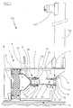
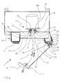
- Figures 1 and 2 are a side view of a bead release device for tire removal machines shown in a first and second operative position respectively, according to the present invention;
- Figure 3 is a detail of Figure 2 on an enlarged scale;
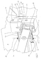
- Figure 4 is a horizontal section through the device of the present invention;
- Figure 5 is a detail of the section of Figure 4, on an enlarged scale.
-
- With reference to said figures, the reference numeral 1 indicates overall a bead release device for
tire removal machines 100 in accordance with the present invention. - In the present description, explicit reference is made to a tire removal machine on which the bead release device 1 is mounted, without thereby intending to limit the use of said device associated with
tire removal machines 100. - Said
machines 100 are of known type and will therefore not be described in particular detail hereinafter. - The device 1 comprises a
movable arm 2 having afirst end 3 removably associated with abase 4. - In the present invention the term "base" means the vertical lateral panel of the
lower frame 101 of thetire removal machine 100. - From the
lower frame 101 there upwardly extends avertical column 102 carrying the support and positioning means 103 for the typical tire removal tool of the known art. - A
bead release tool 6, commonly known as a blade, and positionable about atransverse axis 7, is associated with thearm 2, by means known to the art, at asecond end 5 distant from saidfirst end 3. - The
bead release tool 6 is provided with alever 23 fitted with a handgrip which enables an operator to position the edge of thetool 6 on the bead of a tire of a wheel resting on asupport surface 8. - A
rubberized pad 9 is fixed to thewheel support surface 8 in accordance with the known art. - The
wheel support surface 8 extends onto that portion of thebase 4 below thebead release tool 6 as a surface sufficient to receive that wheel portion concerned in the bead release. - As bead release requires a rather large force, of the order of 1500 kg, the
arm 2 is made to approach and withdraw from the bead of the tire of which it is to be released, by manipulator means. - Advantageously, the function of said manipulator means is performed by a pneumatic cylinder-
piston unit 10 having itspiston rod 10a associated at its upper end with a central region of the arm by mutual coupling means 11 of the known art, and itsjacket 10b housed within the base 4 (Figure 4). - The cylinder-
piston unit 10 rotates thearm 2 within a plane of swivel perpendicular to thebase 4. - Essentially, whereas the
base 4 is disposed vertically, the plane of swivel lies horizontally with respect to the ground - According to a preferred embodiment of the present invention, the
first end 3 of the arm is removably associated with thebase 4 by a locking andrelease system 12. - Specifically, on the
base 4 there is a horizontally extendingbox casing 13 of elongate shape (Figure 1), on the opposite ends of which the vertically extendingsupport surface 8 and the locking andrelease system 12 are respectively located. - In practice, the locking and
release system 12 is rotatably associated with thefirst end 3 of thearm 2 by apin 14 having its axis extending vertically, and is associated with thebase 4 via the box casing 13 (Figures 2 and 4), which is consequently interposed between saidlocking system 12 and the base. - The
arm 2 swivels about thepin 14 positioned on thefirst end 3 of the arm. - The locking and
release system 12 comprises afork 15 rigid with thefirst end 3 of thearm 2 via thepin 14 about which thearm 2 is free to rotate. With said fork 15 (Figure 5) aslider 16 is slidingly associated, to slide within aslide chamber 17 provided between two superposed U-pieces, namely alower U-piece 18 and anupper U-piece 19. - One side of the
lower U-piece 18 is associated with a prolongation of thebase 4, the other side being associated with thebox casing 13. - The upper U-piece is associated with the
lower U-piece 18 by means ofbolts 21 positioned on the sides, but leaving a space between the two, said space forming theslide chamber 17. - In the
upper U-piece 19 an arched slot 22 (Figure 3) is provided, within which theslider 16 can freely slide. - The slider 16 (Figure 5) presents an inverted T cross-section with its
flat base 16a inserted in thechamber 17 and itslongitudinal portion 16b passing through theslot 22 of theupper U-piece 19 and through a hole provided in thefork 15. - A
plate element 39 of S profile is present within the fork and comprises a hole through which thelongitudinal portion 16b of theslider 16 passes. The upper end of thelongitudinal portion 16b of theslider 16 is provided with a thread on which anut 24 is screwed to maintain theplate element 39 and thefork 15 irremovably joined together. - Essentially, when the
slider 16 is made to slide within thechamber 17, it drags with it thefork 15, theplate element 39, and thearm 2 rotatably connected to thefork 15 by thepin 14. - The
slider 16 is limited to sliding along the slot 22 (Figure 3). - The locking and
release system 12 further comprises acam 25 disposed parallel to the axis of thepin 14 and acting on theplate element 39. - The
cam 25 is provided with alever 26 terminating with aknob 27 on which an operator can act to move thecam 25 from a locking position to a release position and vice versa. - When the
cam 25 is in its locking position, it thrustingly abuts against theplate element 39 to prevent theslider 16 from sliding within theslot 22, whereas when thecam 25 is in its release position, the thrust of the cam on theplate element 39 ceases and theslider 16 is free to slide within theslot 22. - When in its locked state, the
flat base 16a of theslider 16, slidingly inserted into theslide chamber 17, abuts against the inner surface of the upper U-piece 19 to prevent thefirst end 3 of thearm 2 from moving relative to the base 4 (Figure 5). - When in its released state, the
flat base 16a of theslider 16, slidingly inserted into theslide chamber 17, is free to slide, by virtue of the gap present between the lower surface of the upper U-piece 19 and theflat base 16a of theslider 16. - This enables the
first end 3 of thearm 2 to be moved. - This movement is guided by the
slider 16, which is limited to sliding within theslot 22. - By virtue of this, the plane of swivel of the
arm 2 rotates about an axis of rotation lying in said plane of swivel and positioned substantially perpendicular to saidbase 4. - In the illustrated example of the present invention, the axis of rotation of the plane of swivel coincides with the axis of the
piston rod 10a of the cylinder-piston unit 10. - Essentially, the plane within which the
arm 2 acts rotates about thepiston 10a of the cylinder-piston unit 10 by moving thefirst end 3 of thearm 2, achieved by sliding theslider 16 within theslot 22 when thecam 25 is in its release position. - Having found the optimum point of operation of the bead release device 1, the
cam 25 is set in the locking position. - By virtue of this rotation of the plane of swivel of the
arm 2 about thepiston rod 10a of the cylinder-piston unit 10, thebead release tool 6, associated with thesecond end 5 of thearm 2, can effectively release the bead from automobile wheels with wheel rims of large diameter (≥ 22"). - In practice, the plane of swivel of the
arm 2 is brought into proximity to the central axis of the wheel holding the tire from which the bead is to be detached. - It should be noted that the optimum condition for effecting bead release is that in which the plane of swivel of the
arm 2 passes through the central axis of the wheel when suitably resting on thesupport surface 8. - To enable the
piston rod 10a of the cylinder-piston unit 10 to operate in an optimum manner, it should undergo small oscillations which follow the rotation of the plane of swivel of thearm 2, when this plane is rotated to detach the bead of tires mounted on large-diameter wheel rims. - According to a preferred embodiment of the present invention, the cylinder-
piston unit 10 is removably associated with thebase 4 by means of a box joint 28 (Figure 4). - Said joint 28 consists of a plate 29 provided with an aperture at its center, a first pair of
sidepieces 30 and a second pair ofsidepieces 31, these pairs being mutually opposing and projecting laterally and perpendicularly to said plate 29. - The sidepieces of said
first pair 30 are prolonged behind the plate 29 by twoappendices 32. - Essentially, the plate 29 of the joint 28 is associated with the
base 4, with thesidepieces arm 2 such as to enable the piston rod to pass through the central aperture of the plate 29. - The first pair of
sidepieces 30 is entirely contained within thebox casing 13, whereas the second pair ofsidepieces 31 lies on the outside of the side walls of thebox casing 13. - In the second pair of sidepieces 31 (Figure 3) two holes are provided through which there are inserted two
pins 34 coaxial with afirst axis 35 extending substantially perpendicular to the plane of swivel of thearm 2, i.e. vertically with respect to the ground. - Said pins 34 enable the
piston rod 10a of the cylinder-piston unit 10 to rotate about thefirst axis 35. - This enables the
piston rod 10a of the cylinder-piston unit 10 to lie rigidly within said plane of swivel while the arm is being moved away from and towards thebase 4. - The
appendices 32 of the first pair ofsidepieces 30 of the joint 28 are embraced by twotangs 36 extending from the end of thejacket 10b of the cylinder-piston unit 10. - Each
tang 36 is provided with a threaded through hole through which ascrew 37 is rotatably screwed. the threadless end of which becomes inserted into a blind hole provided in each of the twoappendices 32. - The two screws are coaxial with a
second axis 38 extending perpendicularly to thefirst axis 35 and substantially parallel to the plane of swivel of thearm 2, i.e. horizontally with respect to the ground. - In practice the first and the
second axis - Said screws 37 enable the
piston rod 10a of the cylinder-piston unit 10 to rotate about thesecond axis 38. - This enables the
piston rod 10a of the cylinder-piston unit 10 substantially to lie rigid within said plane of swivel during the movement of thefirst end 3 of thearm 2. - The rotations about said first and second axis can take place simultaneously, ensuring that the
piston rod 10a assumes an optimum position for effecting the bead release. - As will be apparent from the description, the bead release device for tire removal machines according to the present invention satisfies the requirements and overcomes the drawbacks stated in the introduction to the present description with reference to the known art.
- In this respect, the bead release device of the present invention accomplishes bead release for tires within a very wide range of wheel rim diameters.
- Moreover, said device achieves bead release with greater efficiency and safety, in that the arm swivel plane passes about the central axis of the wheel holding the tire of which the bead is to be released, when this wheel is rested on the support surface for bead release.
- Numerous modifications and variations can be made to the aforedescribed bead release device for tire removal machines by an expert of the art in order to satisfy specific contingent requirements, provided that they lie within the scope of protection of the invention, as defined by the following claims.
Claims (8)
- A bead release device (1) for tire removal machines (100), comprising:characterized in that said first end (3) of the arm (2) is associated with the base (4) by means of a locking and release system (12) enabling said first end (3) of the arm (2) to undergo movement, said movement rotating said plane of swivel of the arm (2) about an axis of rotation lying within said plane of swivel and positioned substantially perpendicular to said base (4).a movable arm (2) having a first end (3) removably associated with a base (4);a positionable bead release tool (6) associated with a second end (5) of the arm (2) distant from said first end (3), to release the tire bead of a wheel resting on a support surface (8);manipulator means (10) for moving said arm (2) within a plane of swivel of the arm (2) lying perpendicular to the base (4);
- A bead release device (1) as claimed in claim 1, wherein said axis of rotation of the plane of swivel lies in that part of the plane of swivel lying between said locking system (12) and said bead release tool (6).
- A bead release device (1) as claimed in claim 1, wherein said locking and release system (12) comprises a cam (25) operable between a locking position and a release position, said release position enabling said first end (3) of the arm (2) to move.
- A bead release device (1) as claimed in claim 3, wherein said locking and release system (12) comprises a slider (16) able to slide within a slot (22) when said cam (25) is in its release position.
- A bead release device (1) as claimed in claim 4, wherein said slot (22) is provided in a U-piece (19) associated with said base (4).
- A bead release device (1) as claimed in claim 1, wherein said manipulator means comprise a pneumatic cylinder-piston unit (10) removably associated with said base (4) and having its piston rod (10a) associated with said arm (2), said cylinder-piston unit (10) being arranged to rotate said arm (2) between a position of approach to and a position of withdrawal from the base (4).
- A bead release device (1) as claimed in claim 6, wherein said cylinder-piston unit (10) is associated with said base (4) in such a manner as to enable the piston rod (10a) to rotate about a first axis (35) positioned substantially perpendicular to the plane of swivel of the arm (2), such that said piston rod (10a) of the cylinder-piston unit (10) can substantially lie rigidly within said plane of swivel during the withdrawal and approach of the arm (2) from and to the base (4).
- A bead release device (1) as claimed in claim 6, wherein said cylinder-piston unit (10) is associated with said base (4) in such a manner as to enable the piston rod (10a) to rotate about a second axis (38) positioned perpendicular to said first axis (35) and substantially parallel to the plane of swivel of the arm (2), such that said piston rod (10a) of the cylinder-piston unit (10) can substantially lie rigidly within said plane of swivel during the movement of the first end (3) of the arm (2).
Applications Claiming Priority (2)
| Application Number | Priority Date | Filing Date | Title |
|---|---|---|---|
| ITRE20030095 | 2003-10-14 | ||
| IT000095A ITRE20030095A1 (en) | 2003-10-14 | 2003-10-14 | BALLASTING DEVICE FOR TIRE CHANGER MACHINES. |
Publications (2)
| Publication Number | Publication Date |
|---|---|
| EP1524134A1 true EP1524134A1 (en) | 2005-04-20 |
| EP1524134B1 EP1524134B1 (en) | 2007-05-16 |
Family
ID=34362440
Family Applications (1)
| Application Number | Title | Priority Date | Filing Date |
|---|---|---|---|
| EP04077782A Active EP1524134B1 (en) | 2003-10-14 | 2004-10-08 | Bead release device for tire removal machines |
Country Status (5)
| Country | Link |
|---|---|
| US (1) | US7100660B2 (en) |
| EP (1) | EP1524134B1 (en) |
| DE (1) | DE602004006474T2 (en) |
| ES (1) | ES2285349T4 (en) |
| IT (1) | ITRE20030095A1 (en) |
Cited By (8)
| Publication number | Priority date | Publication date | Assignee | Title |
|---|---|---|---|---|
| EP1880876A1 (en) * | 2006-07-19 | 2008-01-23 | Giuliano S.P.A. | Bead breaking unit for tyre changing machines |
| EP1897707A1 (en) * | 2006-09-08 | 2008-03-12 | Giuliano S.P.A. | Bead breaking unit for tyre changing machines |
| JP2011031645A (en) * | 2009-07-30 | 2011-02-17 | Onodani Kiko Kk | Device for detaching bead mounted on tire attaching/detaching tool |
| ITMO20090294A1 (en) * | 2009-12-16 | 2011-06-17 | Giuliano Spa | BREAKER GROUP FOR TIRE CHANGER MACHINES |
| EP2524819A1 (en) * | 2011-05-20 | 2012-11-21 | Giuliano Group S.p.A. | Bead breaking unit for tyre changing machines |
| ITMO20110132A1 (en) * | 2011-05-24 | 2012-11-25 | Giuliano Group Spa | BALLONER GROUP PERFECTED FOR TIRE DISMANTLING MACHINES OR SIMILAR |
| CN104908538A (en) * | 2014-03-14 | 2015-09-16 | 西卡姆有限公司 | Bead breaking unit |
| EP3437901A1 (en) * | 2017-08-02 | 2019-02-06 | Robert Bosch GmbH | Bead breaker device |
Families Citing this family (6)
| Publication number | Priority date | Publication date | Assignee | Title |
|---|---|---|---|---|
| US7718189B2 (en) * | 2002-10-29 | 2010-05-18 | Transave, Inc. | Sustained release of antiinfectives |
| DE102007056170A1 (en) * | 2006-12-28 | 2008-11-06 | Dominik Peus | Substance or fuel for producing energy from biomass, is manufactured from biomass, which has higher carbon portion in comparison to raw material concerning percentaged mass portion of elements |
| ITMO20130110A1 (en) * | 2013-04-23 | 2014-10-24 | Giuliano Group Spa | BREAKER GROUP FOR REMOVAL OR SIMILAR MACHINES |
| US9162544B2 (en) | 2013-07-23 | 2015-10-20 | Hennessy Industries, Inc. | Tire changing machine with bead loosener arm |
| ITVR20130252A1 (en) * | 2013-11-22 | 2015-05-23 | Butler Engineering And Marketing S P A | DISASSEMBLY DEVICE FOR A WHEELED WHEEL, AS WELL AS THE MACHINE INCLUDING THIS DEVICE. |
| CA2913652A1 (en) | 2015-11-30 | 2017-05-30 | Donald A. Wilson | Turf tire changer |
Citations (2)
| Publication number | Priority date | Publication date | Assignee | Title |
|---|---|---|---|---|
| EP0512595A1 (en) * | 1991-05-03 | 1992-11-11 | SOCIETA'ITALIANA COSTRUZIONI ELETTROMECCANICHE S.I.C.E. S.p.A. | Bead release unit of highly versatile application |
| EP1026017A2 (en) * | 1999-02-04 | 2000-08-09 | GIULIANO S.r.l. | Machine for mounting and removing special tires |
Family Cites Families (3)
| Publication number | Priority date | Publication date | Assignee | Title |
|---|---|---|---|---|
| US3742999A (en) * | 1971-07-14 | 1973-07-03 | Fmc Corp | Tire mounting and demounting machine |
| IT1258032B (en) * | 1992-02-28 | 1996-02-20 | Corghi Spa | Bead breaker device for tire changer machines |
| ITVR20020013A1 (en) * | 2002-02-12 | 2003-08-12 | Butler Eng & Marketing | Bead breaking and disassembly group of tires from rims, especially for tire changers. |
-
2003
- 2003-10-14 IT IT000095A patent/ITRE20030095A1/en unknown
- 2003-11-07 US US10/702,451 patent/US7100660B2/en active Active
-
2004
- 2004-10-08 EP EP04077782A patent/EP1524134B1/en active Active
- 2004-10-08 DE DE602004006474T patent/DE602004006474T2/en active Active
- 2004-10-08 ES ES04077782T patent/ES2285349T4/en active Active
Patent Citations (2)
| Publication number | Priority date | Publication date | Assignee | Title |
|---|---|---|---|---|
| EP0512595A1 (en) * | 1991-05-03 | 1992-11-11 | SOCIETA'ITALIANA COSTRUZIONI ELETTROMECCANICHE S.I.C.E. S.p.A. | Bead release unit of highly versatile application |
| EP1026017A2 (en) * | 1999-02-04 | 2000-08-09 | GIULIANO S.r.l. | Machine for mounting and removing special tires |
Cited By (24)
| Publication number | Priority date | Publication date | Assignee | Title |
|---|---|---|---|---|
| JP2008024299A (en) * | 2006-07-19 | 2008-02-07 | Giuliano Spa | Bead cutting unit for tire exchanger |
| US7591295B2 (en) | 2006-07-19 | 2009-09-22 | Giuliano S.P.A. | Bead breaking unit for tire changing machines |
| EP1880876A1 (en) * | 2006-07-19 | 2008-01-23 | Giuliano S.P.A. | Bead breaking unit for tyre changing machines |
| EP1897707A1 (en) * | 2006-09-08 | 2008-03-12 | Giuliano S.P.A. | Bead breaking unit for tyre changing machines |
| JP2008062924A (en) * | 2006-09-08 | 2008-03-21 | Giuliano Spa | Bead peeling off unit for tire exchanger |
| JP2011031645A (en) * | 2009-07-30 | 2011-02-17 | Onodani Kiko Kk | Device for detaching bead mounted on tire attaching/detaching tool |
| US8408273B2 (en) | 2009-12-16 | 2013-04-02 | Giuliano Group S.P.A | Bead breaking unit for tire changing machines |
| ITMO20090294A1 (en) * | 2009-12-16 | 2011-06-17 | Giuliano Spa | BREAKER GROUP FOR TIRE CHANGER MACHINES |
| EP2338705A1 (en) | 2009-12-16 | 2011-06-29 | Giuliano Group S.p.A. | Bead breaking unit for tyre changing machines |
| CN102795063B (en) * | 2011-05-20 | 2015-11-25 | 古丽亚诺集团股份公司 | For the bead breaking unit of tyre changing machines |
| EP2524819A1 (en) * | 2011-05-20 | 2012-11-21 | Giuliano Group S.p.A. | Bead breaking unit for tyre changing machines |
| CN102795063A (en) * | 2011-05-20 | 2012-11-28 | 古丽亚诺集团股份公司 | Bead breaking unit for tyre changing machines |
| ITMO20110118A1 (en) * | 2011-05-20 | 2012-11-21 | Giuliano Group Spa | BREAKER GROUP FOR TIRE CHANGER MACHINES |
| US9114675B2 (en) | 2011-05-20 | 2015-08-25 | Giuliano Group S.P.A. | Bead breaking unit for tyre changing machines |
| EP2527166A1 (en) * | 2011-05-24 | 2012-11-28 | Giuliano Group S.p.A. | Bead breaking unit for tyre changing machines |
| US8826962B2 (en) | 2011-05-24 | 2014-09-09 | Giuliano Group S.P.A. | Upgraded bead breaking unit for tyre changing machines or the like |
| ITMO20110132A1 (en) * | 2011-05-24 | 2012-11-25 | Giuliano Group Spa | BALLONER GROUP PERFECTED FOR TIRE DISMANTLING MACHINES OR SIMILAR |
| CN104908538A (en) * | 2014-03-14 | 2015-09-16 | 西卡姆有限公司 | Bead breaking unit |
| EP2930038A1 (en) * | 2014-03-14 | 2015-10-14 | SICAM S.r.l. | Bead breaking unit |
| CN104908538B (en) * | 2014-03-14 | 2018-06-05 | 西卡姆有限公司 | Bead breaking unit |
| US10029520B2 (en) | 2014-03-14 | 2018-07-24 | Sicam S.R.L. | Bead breaking unit |
| RU2670593C2 (en) * | 2014-03-14 | 2018-10-23 | СИКАМ С.р.л. | Inward flanging assembly |
| EP3437901A1 (en) * | 2017-08-02 | 2019-02-06 | Robert Bosch GmbH | Bead breaker device |
| WO2019025363A1 (en) * | 2017-08-02 | 2019-02-07 | Robert Bosch Gmbh | Bead breaker device |
Also Published As
| Publication number | Publication date |
|---|---|
| ES2285349T3 (en) | 2007-11-16 |
| US20050077013A1 (en) | 2005-04-14 |
| ES2285349T4 (en) | 2010-08-09 |
| DE602004006474T2 (en) | 2007-08-30 |
| US7100660B2 (en) | 2006-09-05 |
| ITRE20030095A1 (en) | 2005-04-15 |
| EP1524134B1 (en) | 2007-05-16 |
| DE602004006474D1 (en) | 2007-06-28 |
Similar Documents
| Publication | Publication Date | Title |
|---|---|---|
| EP1524134B1 (en) | Bead release device for tire removal machines | |
| US8291958B2 (en) | Machine for fitting and removing the tires of vehicles | |
| EP1623850B1 (en) | Machine for fitting and removing vehicle wheel tires | |
| EP2282898B1 (en) | A tyre-changing machine and a relative bead-breaking method | |
| EP2338705B1 (en) | Bead breaking unit for tyre changing machines | |
| EP1897709B1 (en) | Machine for fitting and removing vehicle tyres | |
| JP2000296708A (en) | Tire replacement machine for industrial vehicle wheel | |
| EP1258699A2 (en) | Self-centering device for heads or sensors for checking the trim of the wheels of motor vehicles in general | |
| EP2524819B1 (en) | Bead breaking unit for tyre changing machines | |
| US9944136B2 (en) | Machine for removing and fitting wheel tyres for vehicles | |
| US20150224833A1 (en) | Tyre-changing machine | |
| EP2527166B1 (en) | bead breaking unit for tyre changing machines | |
| US9216621B2 (en) | Apparatus for angular positioning of an operating arm of a tire changing machine | |
| EP1584496B1 (en) | Machine for fitting and removing tires of vehicle wheels | |
| US8307874B1 (en) | Tire changing method and machine with angularly positionable drive axis | |
| US6192959B1 (en) | Machine for fitting and removing tires | |
| US5363897A (en) | Tubeless tire demounting tools | |
| US5836368A (en) | Machine for mounting and removing tires onto and from respective wheel rims | |
| US20130146231A1 (en) | Accessory for tyre-changing machines, particularly for the locking of wheel rims for vehicles | |
| JPH0880715A (en) | Device for installing and removing tire | |
| CN111016557B (en) | Machine for mounting and/or dismounting vehicle wheels, in particular truck wheels | |
| US5458177A (en) | Machine for mounting tires on wheel rims | |
| US3557861A (en) | Apparatus for fixing wheels of vehicles from which a tire has to be removed | |
| EP1717064B1 (en) | Tool for fitting and removing vehicle wheel tyres | |
| US8424584B2 (en) | Unit for beading tires in tire changing machines or the like |
Legal Events
| Date | Code | Title | Description |
|---|---|---|---|
| PUAI | Public reference made under article 153(3) epc to a published international application that has entered the european phase |
Free format text: ORIGINAL CODE: 0009012 |
|
| AK | Designated contracting states |
Kind code of ref document: A1 Designated state(s): AT BE BG CH CY CZ DE DK EE ES FI FR GB GR HU IE IT LI LU MC NL PL PT RO SE SI SK TR |
|
| AX | Request for extension of the european patent |
Extension state: AL HR LT LV MK |
|
| 17P | Request for examination filed |
Effective date: 20050630 |
|
| AKX | Designation fees paid |
Designated state(s): DE ES FR GB IT |
|
| GRAP | Despatch of communication of intention to grant a patent |
Free format text: ORIGINAL CODE: EPIDOSNIGR1 |
|
| GRAS | Grant fee paid |
Free format text: ORIGINAL CODE: EPIDOSNIGR3 |
|
| GRAA | (expected) grant |
Free format text: ORIGINAL CODE: 0009210 |
|
| AK | Designated contracting states |
Kind code of ref document: B1 Designated state(s): DE ES FR GB IT |
|
| REG | Reference to a national code |
Ref country code: GB Ref legal event code: FG4D |
|
| REF | Corresponds to: |
Ref document number: 602004006474 Country of ref document: DE Date of ref document: 20070628 Kind code of ref document: P |
|
| REG | Reference to a national code |
Ref country code: ES Ref legal event code: FG2A Ref document number: 2285349 Country of ref document: ES Kind code of ref document: T3 |
|
| PLBE | No opposition filed within time limit |
Free format text: ORIGINAL CODE: 0009261 |
|
| STAA | Information on the status of an ep patent application or granted ep patent |
Free format text: STATUS: NO OPPOSITION FILED WITHIN TIME LIMIT |
|
| 26N | No opposition filed |
Effective date: 20080219 |
|
| PGFP | Annual fee paid to national office [announced via postgrant information from national office to epo] |
Ref country code: GB Payment date: 20101029 Year of fee payment: 7 |
|
| GBPC | Gb: european patent ceased through non-payment of renewal fee |
Effective date: 20111008 |
|
| PG25 | Lapsed in a contracting state [announced via postgrant information from national office to epo] |
Ref country code: GB Free format text: LAPSE BECAUSE OF NON-PAYMENT OF DUE FEES Effective date: 20111008 |
|
| REG | Reference to a national code |
Ref country code: FR Ref legal event code: PLFP Year of fee payment: 12 |
|
| REG | Reference to a national code |
Ref country code: FR Ref legal event code: PLFP Year of fee payment: 13 |
|
| REG | Reference to a national code |
Ref country code: FR Ref legal event code: PLFP Year of fee payment: 14 |
|
| REG | Reference to a national code |
Ref country code: DE Ref legal event code: R082 Ref document number: 602004006474 Country of ref document: DE Representative=s name: LORENZ & KOLLEGEN PATENTANWAELTE PARTNERSCHAFT, DE Ref country code: DE Ref legal event code: R081 Ref document number: 602004006474 Country of ref document: DE Owner name: NEXION S.P.A., IT Free format text: FORMER OWNER: CORGHI S.P.A., CORREGGIO, REGGIO EMILIA, IT |
|
| REG | Reference to a national code |
Ref country code: ES Ref legal event code: PC2A Effective date: 20180529 Ref country code: ES Ref legal event code: PC2A Owner name: NEXION S.P.A. Effective date: 20180529 |
|
| REG | Reference to a national code |
Ref country code: FR Ref legal event code: CD Owner name: NEXION S.P.A., IT Effective date: 20180620 |
|
| REG | Reference to a national code |
Ref country code: FR Ref legal event code: PLFP Year of fee payment: 15 |
|
| P01 | Opt-out of the competence of the unified patent court (upc) registered |
Effective date: 20230530 |
|
| PGFP | Annual fee paid to national office [announced via postgrant information from national office to epo] |
Ref country code: ES Payment date: 20231110 Year of fee payment: 20 |
|
| PGFP | Annual fee paid to national office [announced via postgrant information from national office to epo] |
Ref country code: IT Payment date: 20231027 Year of fee payment: 20 Ref country code: FR Payment date: 20231026 Year of fee payment: 20 Ref country code: DE Payment date: 20231027 Year of fee payment: 20 |