EP2527075A1 - Welded structure and welding method - Google Patents
Welded structure and welding method Download PDFInfo
- Publication number
- EP2527075A1 EP2527075A1 EP10843872A EP10843872A EP2527075A1 EP 2527075 A1 EP2527075 A1 EP 2527075A1 EP 10843872 A EP10843872 A EP 10843872A EP 10843872 A EP10843872 A EP 10843872A EP 2527075 A1 EP2527075 A1 EP 2527075A1
- Authority
- EP
- European Patent Office
- Prior art keywords
- joint portion
- cavity
- ring gear
- welding
- joined
- Prior art date
- Legal status (The legal status is an assumption and is not a legal conclusion. Google has not performed a legal analysis and makes no representation as to the accuracy of the status listed.)
- Granted
Links
Images







Classifications
-
- B—PERFORMING OPERATIONS; TRANSPORTING
- B23—MACHINE TOOLS; METAL-WORKING NOT OTHERWISE PROVIDED FOR
- B23K—SOLDERING OR UNSOLDERING; WELDING; CLADDING OR PLATING BY SOLDERING OR WELDING; CUTTING BY APPLYING HEAT LOCALLY, e.g. FLAME CUTTING; WORKING BY LASER BEAM
- B23K26/00—Working by laser beam, e.g. welding, cutting or boring
- B23K26/20—Bonding
- B23K26/21—Bonding by welding
- B23K26/24—Seam welding
- B23K26/28—Seam welding of curved planar seams
-
- B—PERFORMING OPERATIONS; TRANSPORTING
- B23—MACHINE TOOLS; METAL-WORKING NOT OTHERWISE PROVIDED FOR
- B23K—SOLDERING OR UNSOLDERING; WELDING; CLADDING OR PLATING BY SOLDERING OR WELDING; CUTTING BY APPLYING HEAT LOCALLY, e.g. FLAME CUTTING; WORKING BY LASER BEAM
- B23K26/00—Working by laser beam, e.g. welding, cutting or boring
- B23K26/16—Removal of by-products, e.g. particles or vapours produced during treatment of a workpiece
-
- B—PERFORMING OPERATIONS; TRANSPORTING
- B23—MACHINE TOOLS; METAL-WORKING NOT OTHERWISE PROVIDED FOR
- B23K—SOLDERING OR UNSOLDERING; WELDING; CLADDING OR PLATING BY SOLDERING OR WELDING; CUTTING BY APPLYING HEAT LOCALLY, e.g. FLAME CUTTING; WORKING BY LASER BEAM
- B23K33/00—Specially-profiled edge portions of workpieces for making soldering or welding connections; Filling the seams formed thereby
- B23K33/004—Filling of continuous seams
- B23K33/006—Filling of continuous seams for cylindrical workpieces
-
- B—PERFORMING OPERATIONS; TRANSPORTING
- B23—MACHINE TOOLS; METAL-WORKING NOT OTHERWISE PROVIDED FOR
- B23K—SOLDERING OR UNSOLDERING; WELDING; CLADDING OR PLATING BY SOLDERING OR WELDING; CUTTING BY APPLYING HEAT LOCALLY, e.g. FLAME CUTTING; WORKING BY LASER BEAM
- B23K2101/00—Articles made by soldering, welding or cutting
- B23K2101/008—Gears
-
- F—MECHANICAL ENGINEERING; LIGHTING; HEATING; WEAPONS; BLASTING
- F16—ENGINEERING ELEMENTS AND UNITS; GENERAL MEASURES FOR PRODUCING AND MAINTAINING EFFECTIVE FUNCTIONING OF MACHINES OR INSTALLATIONS; THERMAL INSULATION IN GENERAL
- F16H—GEARING
- F16H48/00—Differential gearings
- F16H48/38—Constructional details
- F16H2048/382—Methods for manufacturing differential gearings
-
- F—MECHANICAL ENGINEERING; LIGHTING; HEATING; WEAPONS; BLASTING
- F16—ENGINEERING ELEMENTS AND UNITS; GENERAL MEASURES FOR PRODUCING AND MAINTAINING EFFECTIVE FUNCTIONING OF MACHINES OR INSTALLATIONS; THERMAL INSULATION IN GENERAL
- F16H—GEARING
- F16H48/00—Differential gearings
- F16H48/38—Constructional details
- F16H2048/385—Constructional details of the ring or crown gear
-
- F—MECHANICAL ENGINEERING; LIGHTING; HEATING; WEAPONS; BLASTING
- F16—ENGINEERING ELEMENTS AND UNITS; GENERAL MEASURES FOR PRODUCING AND MAINTAINING EFFECTIVE FUNCTIONING OF MACHINES OR INSTALLATIONS; THERMAL INSULATION IN GENERAL
- F16H—GEARING
- F16H55/00—Elements with teeth or friction surfaces for conveying motion; Worms, pulleys or sheaves for gearing mechanisms
- F16H55/02—Toothed members; Worms
- F16H55/17—Toothed wheels
-
- Y—GENERAL TAGGING OF NEW TECHNOLOGICAL DEVELOPMENTS; GENERAL TAGGING OF CROSS-SECTIONAL TECHNOLOGIES SPANNING OVER SEVERAL SECTIONS OF THE IPC; TECHNICAL SUBJECTS COVERED BY FORMER USPC CROSS-REFERENCE ART COLLECTIONS [XRACs] AND DIGESTS
- Y10—TECHNICAL SUBJECTS COVERED BY FORMER USPC
- Y10T—TECHNICAL SUBJECTS COVERED BY FORMER US CLASSIFICATION
- Y10T403/00—Joints and connections
- Y10T403/47—Molded joint
- Y10T403/477—Fusion bond, e.g., weld, etc.
Definitions
- the present invention relates to a welded structure of plural parts joined together by welding such as, for example, a differential case and a ring gear of a differential device (differential gear) of an automobile, and a welding method.
- FIG. 11 shows a conventional example of a welded structure between a conventional differential case 100 and a ring gear 102.
- a hypoid gear is formed in a teeth portion 102a of the ring gear 102.
- a groove 104 is provided in the joint surface between the differential case 100 and the ring gear 102.
- one end of the weld beads 109 may be repeatedly subjected to large compressive stress and tensile stress, which may result in insufficient weld strength. Even if a groove 110 is provided in the differential case 108 in its joint surface with the ring gear 106, such groove cannot provide an effect of reducing stresses applied to the end on the groove 110 side of the weld beads 109.
- Patent Document 1 discloses a technique in which a flange member is disposed between a small gear wheel member and a large gear wheel member, and the flange member is joined to the large gear wheel member with the outer periphery of the flange member being in contact with the inner periphery of the large gear wheel member such that it is welded from both sides in the central axis direction of the large gear wheel member.
- Patent Document 1 JP 10(1998)-231918A
- the present invention was made to solve the above problem and has an object to provide a welded structure and a welding method with which weld strength and weld quality can be improved.
- One aspect of the present invention made to solve the above problem provides a welded structure of a first member and a second member joined together by welding, wherein the first member includes a second member joint portion joined to the second member, the second member includes a first member joint portion joined to the first member, when the first member and the second member are aligned along a first direction and a second direction is a direction intersecting the first direction, the welded structure includes a cavity formed between the first member joint portion and the second member joint portion, and a welded portion formed between the cavity and each end in the second direction of a joint surface where the first member joint portion and the second member joint portion are joined together.
- gas that may be generated during welding can be exhausted into the cavity, so that formation of blow holes is suppressed. Also, stress that may act to lower weld strength hardly remains at the interface of the joined portion between the first member and the second member on cooling after welding. Thus, weld strength and weld quality are improved.
- gas exhausted into the cavity during welding can escape from the through hole, so that formation of pin holes in the welded portion is prevented.
- the through hole also allows for observation of the inside of the cavity to check if the welded portion has been formed through to the cavity, so that weld quality is improved. Also, any water droplets due to possible condensation inside the cavity on cooling after welding can be drained from the through hole. Therefore, corrosion of the welded portion can be prevented.
- the first member is an annular member whose radial direction coincides with the first direction
- the welded structure includes a press-fit portion on one of an inner peripheral surface of the first member and an abutment surface of the first member joint portion of the second member that abuts against the inner peripheral surface for allowing press-fit to be made with a press-fit interference between the inner peripheral surface and the abutment surface.
- the second member is press-fitted into the first member, or, the first member is press-fitted into the second member.
- the first member and the second member are maintained in their positions during welding. Therefore, weld distortion can be reduced.
- the cavity includes a first cavity and a second cavity, the first cavity and the second cavity are arranged respectively on both sides of the press-fit portion in the second direction.
- the irradiated laser beam is interrupted by the press-fit portion. Therefore the welded portion already formed by a laser beam irradiated from one side can be prevented from being re-heated by a laser beam irradiated from the other side. Also, even when welding is performed simultaneously from the above-noted two directions, the laser beams irradiated from the two directions do not interfere with each other.
- the cavity is formed by a groove provided at least to one of the first member and the second member.
- the tolerable amount of gas exhausted into the cavity can readily be adjusted by adjustment of the groove depth.
- the second member is made of a material that generates more gas when molten than the first member, and the welded portion is formed along a direction inclined toward the first member side relative to the joint surface.
- the melting amount of the second member that generates more gas when molten can be reduced during welding, so that formation of blow holes is suppressed.
- the present invention provides a welded structure of a first member and a second member joined together by welding, wherein the first member includes a second member joint portion joined to the second member, the second member includes a first member joint portion joined to the first member, when the first member and the second member are aligned along a first direction and a second direction is a direction intersecting the first direction, the welded structure includes a welded portion formed at least at each end in the second direction of a joint surface where the first member joint portion and the second member joint portion are joined together, the second member is made of a material that generates more gas when molten than the first member, and the welded portion is formed along a direction inclined toward the first member side relative to the joint surface.
- the melting amount of the second member that generates more gas when molten can be reduced during welding. Accordingly, formation of blow holes is suppressed.
- the first member is a ring gear of a differential gear
- the second member is a differential case which is a housing member of the differential gear
- the present invention provides a welding method for joining a first member and a second member together by welding, wherein, when the first member and the second member are aligned along a first direction, and a second direction is a direction intersecting the first direction, for joining together a second member joint portion provided to the first member to be joined to the second member and a first member joint portion provided to the second member to be joined to the first member, a cavity is formed between the first member joint portion and the second member joint portion, and welding is performed from both ends of the joint surface in the second direction so as to form welds between both ends of the joint surface in the second direction and the cavity.
- the first member or the second member is formed with a through hole extending from outside into the cavity.
- the first member is formed in an annular form such that its radial direction coincides with the first direction
- the first member joint portion of the second member is formed with an abutment surface to be abutted against an inner peripheral surface of the first member
- the first member and the second member are press-fitted to each other with a press-fit interference between the inner peripheral surface and the abutment surface.
- the present invention preferably provides a welding method for joining a first member and a second member together by welding, wherein, when the first member and the second member are aligned along a first direction, and a second direction is a direction intersecting the first direction, for joining together a second member joint portion provided to the first member to be joined to the second member and a first member joint portion provided to the second member to be joined to the first member, the second member is made of a material that generates more gas when molten than the first member, and welding is performed from both ends of the joint surface in the second direction so as to form welds along a direction inclined toward the first member side relative to the joint surface at least at both ends of the second direction of the joint surface where the first member joint portion and the second member joint portion are joined together.
- weld strength and weld quality can be improved.
- FIG. 1 is a plan view of a welded structure between a differential case 10 and a ring gear 12.
- the differential case 10 is shown partially, i.e., only the vicinity of its joint portion to the ring gear 12 is shown.
- the differential case 10 and the ring gear 12 are joined by welding, with the differential case 10 being inserted into the inner periphery of the annular ring gear 12.
- the differential case 10 is one example of a "second member” in the claims.
- the ring gear 12 is one example of a "first member” in the claims.
- welding is performed from two directions on both sides of the ring gear 12 with respect to the central axis S direction of the ring gear 12 (direction perpendicular to the paper plane of FIG.
- second weld beads 38 which are the weld or welded portion on the side opposite to the side shown in FIG. 1 are formed in an annular shape along the inner periphery of the ring gear 12 similarly to the first weld beads 14.
- the differential case 10 is a housing member accommodating therein components for transmitting power (such as a pinion shaft, a pinion gear, a side gear) to a drive shaft (not shown).
- the ring gear 12 is a gear wheel member meshing with a drive pinion (not shown) that transmits power from an engine (not shown).
- the differential case 10 is made of cast iron, while the ring gear 12 is made of steel.
- FIG. 2 is a cross section along A-A in FIG. 1
- FIG. 3 is an enlarged view of the joint portion between the differential case 10 and the ring gear 12 in FIG. 2 .
- the differential case 10 and the ring gear 12 are aligned in the radial direction (a first direction) of the ring gear 12.
- the central axis S direction of the ring gear 12 is a direction (a third direction) orthogonal to the radial direction of the ring gear 12.
- the direction (a second direction) in which the first weld beads 14 and the second weld beads 38 are formed in a joint surface 25 coincides with the direction (the third direction, or the central axis S direction) orthogonal to the radial direction of the ring gear 12.
- the differential case 10 is provided with a gear joint portion 22 which will be joined to the ring gear 12.
- the gear joint portion 22 is one example of a "first member joint portion” in the claims, and one part of the differential case 10.
- the "first member joint portion” in the claims is one part of the "second member”.
- the ring gear 12 is provided with a case joint portion 20 which will be joined to the differential case 10.
- the case joint portion 20 is one example of a "second member joint portion” in the claims, and one part of the ring gear 12.
- the "second member joint portion" in the claims is one part of the "first member”.
- the first weld beads 14 are formed from one end 27a, while the second weld beads 38 are formed from the other end 27b, of both ends in the central axis S direction of the ring gear 12.
- the ring gear 12 is formed of the case joint portion 20, a connecting portion 18, and a toothed portion 16 aligned in this order along the radial direction from the joint surface 25 toward the outer periphery of the ring gear 12.
- the connecting portion 18 connects to the case joint portion 20 and the toothed portion 16, i.e., couples the case joint portion 20 and the toothed portion 16.
- the toothed portion 16 is formed with a teeth portion 16a on its outer periphery. In this example, a helical gear is formed in the teeth portion 16a.
- the gear joint portion 22 of the differential case 10 is provided with an abutment surface 21 to be abutted against an inner peripheral surface 12a of the ring gear 12 before welding the differential case 10 and the ring gear 12 together.
- This abutment surface 21 includes a press-fit portion 24 and a first groove 26 and a second groove 28 on both sides of this press-fit portion 24.
- the press-fit portion 24 is provided substantially at the center of the abutment surface 21 in the central axis S direction of the ring gear 12. This press-fit portion 24 is provided for allowing the differential case 10 and the ring gear 12 to make press-fit with each other with a press-fit interference (allowance) between the inner peripheral surface 12a and the abutment surface 21 when inserting the differential case 10 into the inner peripheral surface 12a of the ring gear 12.
- surface portions of the abutment surface 21 located on both sides, in the central axis S direction of the ring gear 12, of the first groove 26, the press-fit portion 24, and the second groove 28 may serve as the press-fit portion.
- the first groove 26 and the second groove 28 respectively form a first cavity 30 and a second cavity 32 between themselves and the inner peripheral surface 12a of the ring gear 12.
- a press-fit portion may be provided in the inner peripheral surface 12a of the ring gear 12 instead of providing the press-fit portion 24 in the abutment surface 21 of the differential case 10.
- the gear joint portion 22 of the differential case 10 is formed with through holes 34 extending from outside of the differential case 10 into the first cavity 30. Another through holes may additionally be provided so as to extend through the differential case 10 from outside into the second cavity 32. Alternatively, through holes may be formed in the case joint portion 20 of the ring gear 12 instead of or in addition to the through holes in the gear joint portion 22 of the differential case 10.
- first weld beads 14 and the second weld beads 38 are a layer of welded metal deposited in the joined portion of the gear joint portion 22 of the differential case 10 and the case joint portion 20 of the ring gear 12 when they are joined together by welding.
- the first weld beads 14 are formed between one end 27a of the joint surface 25 in the central axis S direction and the first cavity 30, while the second weld beads 38 are formed between the other end 27b of the joint surface 25 in the central axis S direction and the second cavity 32.
- the first weld beads 14 and the second weld beads 38 are formed along directions inclined at an angle ⁇ , relative to the abutment surface 21 of the gear joint portion 22 of the differential case 10.
- first cavity 30 and the second cavity 32 there are provided the first cavity 30 and the second cavity 32.
- Welding is performed such as to form the first weld beads 14 and the second weld beads 38 respectively between one end 27a of the joint surface 25 and the first cavity 30, and between the other end 27b of the joint surface 25 and the second cavity 32 (hereinafter referred to as "piercing welding").
- piercing welding This allows the gas generated when the differential case 10 melts during welding to be exhausted into the first cavity 30 and the second cavity 32. Therefore, by such piercing welding with the first cavity 30 and the second cavity 32, the formation of blow holes can be prevented.
- a tolerable amount of gas exhausted into the first cavity 30 and the second cavity 32 can be readily adjusted by adjusting the depth of the first groove 26 and the second groove 28.
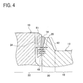
- a non-welded portion 48 is provided between the first weld beads 14 and the first cavity 30.
- the non-welded portion 48 will inhibit the contraction in directions indicated by arrows, whereby there remains some tensile stress as indicated by arrows in first weld bead interface 61.
- Such residual tensile stress may cause cracks to be readily formed from the first weld bead interface 61 when a load is applied thereto in actual operation of the differential gear.
- the press-fit portion 24 is provided to the abutment surface 21 of the gear joint portion 22 of the differential case 10.
- the gear joint portion 22 is inserted into the inner periphery of the ring gear 12 with the press-fit portion 24 press-fitted into the inner peripheral surface 12a of the ring gear 12. Therefore, the positional relationship between the differential case 10 and the ring gear 12 can be maintained before and after welding. Accordingly, weld distortion can be reduced by the provision of the press-fit portion 24.
- the press-fit portion 24 is provided at a position further in the direction in which a laser beam 23 is irradiated. Therefore, the laser beam 23 irradiated to form the first weld beads 14 and the second weld beads 38 hits against and is interrupted by the press-fit portion 24. Accordingly, when forming weld beads on one side after forming weld beads on the other side (for example, when forming the second weld beads 38 after forming the first weld beads 14), there is no risk of re-heating the previously formed weld beads on one side with the laser beam for forming the weld beads on the other side.
- the press-fit portion 24 being provided at a position further in the direction in which the laser beam 23 is irradiated, weld strength and weld quality can be improved.
- laser beams 23 are simultaneously irradiated from two directions on both sides in the central axis S direction of the ring gear 12 to form the first weld beads 14 and the second weld beads 38, they do not interfere with each other since the laser beams 23 from two directions hit against and are interrupted by the press-fit portion 24. Accordingly, with the press-fit portion 24 being provided at a position further in the direction in which the laser beam 23 is irradiated, safety in the welding equipment can be improved.
- first weld beads 14 and the second weld beads 38 are formed from two directions on both sides in the central axis S direction of the ring gear 12 to form the first weld beads 14 and the second weld beads 38. Therefore, a molten component (such as Ni) of the weld wire 40 is contained more at a smaller weld penetration depth than at a larger weld penetration depth both in the first weld beads 14 and the second weld beads 38, i.e., the distribution of the molten component of the weld wire 40 in the weld penetration direction is more or less equal. Accordingly, the first weld beads 14 and the second weld beads 38 have a uniform material strength against bending stress applied thereto in actual operation of the differential gear.
- weld strength and weld quality can be improved by performing welding from two directions on both sides in the central axis S direction of the ring gear 12 to form the first weld beads 14 and the second weld beads 38.
- the distribution of heat input can be made uniform during welding along the central axis S direction of the ring gear 12 in portions where the first weld beads 14 and the second weld beads 38 will be formed. Therefore, weld distortion can be suppressed by performing welding from two directions on both sides in the central axis S direction of the ring gear 12.
- welding is performed to form the first weld beads 14 and the second weld beads 38 along directions inclined at an angle ⁇ relative to the abutment surface 21 of the gear joint portion 22 of the differential case 10 toward the ring gear 12 side (hereinafter referred to as "inclined welding"). Therefore, the melting amount of the differential case 10 (made of cast iron) that produces more gas when molten than the ring gear 12 (made of steel) during welding can be reduced, whereby the amount of generated gas can be reduced. Accordingly, the formation of blow holes can be suppressed by performing the inclined welding. Also, in the event of rupture of the first weld beads 14 and the second weld beads 38, the ring gear 12 will be caught in the differential case 10 and not come off, so that the ring gear 12 is prevented from dropping out.
- through holes 34 are provided to extend through the differential case 10 from outside into the first cavity 30. Therefore, by observing the reflection light of the laser beam 23 in the first groove 26 during welding through the through holes 34, it can be determined whether or not piercing welding has been successfully done wherein the first weld beads 14 are formed through to the first cavity 30. Accordingly, weld quality can certainly be improved by the provision of the through holes 34.
- the dimension of the connecting portion 18 is denoted by ta
- the dimension between the end face 20a and the end face 20b of the case joint portion 20 is denoted by tb
- the dimension of the toothed portion 16 is denoted by tc.
- a thrust load is applied to the toothed portion 16 in the central axis S direction of the ring gear 12 (direction indicated by a thick arrow in FIG. 2 ) by power transmission from a drive pinion (not shown) in actual operation.
- a thrust load external force
- the first weld beads 14 and the second weld beads 38 are subjected to compressive stress or tensile stress.
- the case joint portion 20 has an increased modulus of section and improved bending rigidity. Because of this, despite the thrust load acting in the central axis S direction, the compressive stress and tensile stress applied to the first weld beads 14 and the second weld beads 38 are reduced. Thus, by making the dimensions to be ta ⁇ tb, weld strength between the differential case 10 and the ring gear 12 is improved.
- the case joint portion 20 of the ring gear 12 has a protruded portion 42 extending out from the connecting portion 18 in the central axis S direction of the ring gear 12.
- the radial dimension of the ring gear 12 is small and an opposite surface to the joint surface 25 in the radial direction of the ring gear 12 is open or exposed. Therefore, this protruded portion 42 has a small heat capacity and low rigidity.
- the protruded portion 42 In welding at the joint surface 25, therefore, as the temperature in the protruded portion 42 rises and its Young's module lowers, the protruded portion 42 can readily deform with expansion thereof as indicated by a broken line in a direction of an arrow in FIG. 5 .
- the protruded portion 42 can also deform with contraction thereof as the temperature falls on cooling after welding. Therefore, formation of cracks in the first weld beads 14 and the second weld beads 38 and their thermally affected parts can be suppressed during welding and on cooling after welding. Thus, by making the dimensions to be ta ⁇ tb, weld quality is improved.
- the radial dimension of the ring gear 12 in its protruded portion 42 may be made as small as possible to further reduce its heat capacity and to lower the rigidity.
- weld strength can be secured without making the penetration depth of the first weld beads 14 and the second weld beads 38 very large. Heat input during welding is thereby reduced.
- weld distortion and welding equipment cost can be reduced.
- the dimensions are made to be tb ⁇ tc as shown in FIG. 2 .
- the dimension tb of the case joint portion 20 By making the dimension tb of the case joint portion 20 smaller, the weight of the ring gear 12 is reduced.
- the case joint portion 20 has a smaller cross-sectional area, so that stirring resistance between lubricating oil (not shown) filling up around the ring gear 12 and the ring gear 12 generated when the ring gear 12 rotates around the central axis S in actual operation of the differential gear can be reduced.
- td the dimension between the end face 22a and the end face 22b of the gear joint portion 22 of the differential case 10 is denoted by td.
- the dimensions are made to be tb ⁇ td.
- a step 44 is formed respectively between the end face 20a of the case joint portion 20 of the ring gear 12 and the end face 22a of the gear joint portion 22 of the differential case 10, and between the end face 20b of the case joint portion 20 of the ring gear 12 and the end face 22b of the gear joint portion 22 of the differential case 10.
- the weld wire 40 can be conformed (contacted) to the portions of these steps 44 as shown in FIG. 5 so that the weld wire 40 will not be displaced further toward the differential case 10.
- the dimensions to be tb ⁇ td displacement of the weld wire 40 during welding can be prevented.
- the end faces 20a and 20b in the central axis S direction of the case weld 20 of the ring gear 12 are formed flat along the radial direction of the ring gear 12. Therefore, the differential case 10 and the ring gear 12 can be accurately positioned by placing a positioning jig 46 for the ring gear 12 in contact with one or both of the end faces 20a and 20b.
- FIG. 6 shows an example where the differential case 10 and the ring gear 12 are positioned with the positioning jig 46 placed in contact with the end face 20a.
- Either the end face 20a alone, or the end face 20b alone, may be formed flat along the radial direction of the ring gear 12.
- the differential case 10 and the ring gear 12 can be accurately positioned using the positioning jig 46.
- Example 2 is different from Example 1 in that no press-fit portion 24 is formed in the differential case 10. It is also different from Example 1 in that the differential case 10 is formed with a groove 51 in the abutment surface 21 so that it includes a cavity 52 formed between this groove 51 and the inner peripheral surface 12a of the ring gear 12.
- the cavity 52 has a larger cross-sectional area than the sum of the cross-sectional areas of the first cavity 30 and the second cavity 32 of Example 1. Therefore, more gas that may be generated when the differential case 10 melts during welding can be exhausted into the cavity 52.
- the formation of blow holes can be more reliably suppressed because of the increased tolerable amount of gas that can be exhausted into the cavity 52. Also, because no press-fit portion 24 is provided, the number of mechanical machining processes is reduced, and the production cost can be reduced.
- the gear joint portion 22 before welding is provided with abutment surfaces 53 and 55 on both sides of the groove 51 to be abutted against the case joint portion 20.
- no through holes 34 are provided, if, due to the increased tolerable amount of gas that can be exhausted into the cavity 52, pin hole defects of the first weld beads 14 and the second weld beads 38 caused by expansion of gas inside the cavity 52 are unlikely to occur.
- Example 3 There could be Example 3 as shown in FIG. 8 .
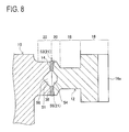
- a groove 54 is provided in the inner peripheral surface 12a of the ring gear 12 in addition to the groove 51 in Example 2.
- it includes a cavity 56 formed between the grooves 51 and 54.
- This cavity 56 has a larger cross-sectional area than that of the cavity 52 of Example 2. Therefore, more gas that may be generated when the differential case 10 melts during welding can be exhausted into the cavity 56.
- the formation of blow holes can be even more reliably suppressed because of the increased tolerable amount of gas that can be exhausted into the cavity 56 by the provision of the groove 54 in the ring gear 12.
- Example 4 There could be Example 4 as shown in FIG. 9 .
- the inner peripheral surface 12a of the ring gear 12 is split into parts which are respectively positioned differently in the radial direction.
- the inner peripheral surface 12a forms the joint surface 25 where the case joint portion 20 and the gear joint portion 22 are joined together.
- the direction (a second direction) in which the first weld beads 14 and the second weld beads 38 are formed in the joint surface 25 coincided with the direction (a third direction, central axis S direction) orthogonally intersecting the radial direction of the ring gear 12 in the previously described Examples 1 to 3
- the direction (the second direction) in which the first weld beads 14 and the second weld beads 38 are formed in the joint surface 25 does not coincide with the direction (the third direction, central axis S direction) orthogonally intersecting the radial direction of the ring gear 12 in Examples 4 and 5 described below.
- the first weld beads 14 and the second weld beads 38 are at different positions respectively in the radial direction of the ring gear 12.
- a laser beam 23 irradiated in the central axis S direction of the ring gear 12 during welding hits against and is interrupted by the differential case 10 or the ring gear 12. Therefore, the laser beam 23 irradiated to form weld beads on one side does not irradiate and re-heat the weld beads formed on the other side. Accordingly, weld strength and weld quality can be improved.
- the laser beams 23 irradiated from two directions do not interfere with each other. Therefore, safety of the welding equipment is improved. Also, since there is no need to perform inclined welding, the welding equipment can be made simple and the production cost can be reduced. In the event of rupture of the first weld beads 14 and the second weld beads 38, the ring gear 12 will be caught in the differential case 10 and not come off, so that the ring gear 12 is prevented from dropping out.
- the differential case 10 and the ring gear 12 are butted against each other in the central axis S direction of the ring gear 12 at a butted portion 58. Thereby they have an increased strength against the thrust load.
- dimensions are made to be ta ⁇ tb1, where tb1 represents the dimension of the case joint portion 20 in the central axis S direction of the ring gear 12.
- the differential case 10 when inserting the differential case 10 into the inner periphery of the ring gear 12 before welding, it is preferable to press fit the differential case 10 into the inner peripheral surface 12a of the ring gear 12 using at least one of the abutment surfaces 53 and 55.
- through holes extending from the first cavity 30 to outside, or through holes extending from the second cavity 32 to outside may be provided in the differential case 10.
- the previously described step 44 may be provided between the gear joint portion 22 and the case joint portion 20 as required.
- Example 5 There could be Example 5 as shown in FIG. 10 .
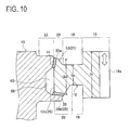
- the joint surface 25 where the case joint portion 20 and the gear joint portion 22 are joined together consists of a surface formed of the inner peripheral surface 12a of the ring gear 12 and the end face 20b of the case joint portion 20 (surface formed by connecting a plurality of surfaces oriented in different directions).
- the second weld beads 38 are formed along the end face 20b of the case joint portion 20 so that the second weld beads 38 are formed substantially in the radial direction of the ring gear 12.
- weld strength is improved even when, for example, a thrust load is unevenly applied to the upper side in the drawing as shown in FIG. 10 of the toothed portion 16 by power transmission from the drive pinion (not shown) in actual operation of the differential gear.
- weld strength may be improved by inverting the directions in which the first weld beads 14 and the second weld beads 38 are formed from those of the example of FIG. 10 .
- the laser beam 23 irradiated to form weld beads on one side does not re-heat the weld beads already formed on the other side during welding. Accordingly, weld quality can be improved. Moreover, even when the laser welding is performed from two directions on both sides of the central axis S direction of the ring gear 12, the laser beams 23 irradiated from two directions do not interfere with each other. Therefore, safety of the welding equipment can be improved.
- dimensions are made to be ta ⁇ tb2, where tb2 represents the dimension of the case joint portion 20 in the central axis S direction of the ring gear 12.
- the differential case 10 When inserting the differential case 10 into the inner periphery of the ring gear 12 before welding, it is preferable to press fit the differential case 10 into the inner peripheral surface 12a of the ring gear 12 using the abutment surface 53.
- a cavity 60 is formed between the groove 59 in the abutment surface 21 and the inner peripheral surface 12a.
- through holes extending from this cavity 60 to outside may be formed in the differential case 10.
- the dimension tb of the case joint portion 20 in the central axis S direction of the ring gear 12 may be made larger than the dimension tc of the toothed portion 16 (tb > tc).
Landscapes
- Engineering & Computer Science (AREA)
- Physics & Mathematics (AREA)
- Optics & Photonics (AREA)
- Mechanical Engineering (AREA)
- Plasma & Fusion (AREA)
- Retarders (AREA)
- Laser Beam Processing (AREA)
- General Details Of Gearings (AREA)
- Gears, Cams (AREA)
Abstract
Description
- The present invention relates to a welded structure of plural parts joined together by welding such as, for example, a differential case and a ring gear of a differential device (differential gear) of an automobile, and a welding method.
- One example of a welded structure of plural parts joined together by welding is a welded structure between, for example, a differential case and a ring gear of a differential device (hereinafter, "differential gear") of an automobile.
FIG. 11 shows a conventional example of a welded structure between a conventionaldifferential case 100 and aring gear 102. A hypoid gear is formed in ateeth portion 102a of thering gear 102. In the conventional example ofFIG. 11 , agroove 104 is provided in the joint surface between thedifferential case 100 and thering gear 102. Thus, compressive stress and shear stress onweld beads 105 caused by a load applied in directions shown in the drawing in actual operation of the differential gear are less concentrated on aweld bead end 105a. - However, in a conventional example in which a helical gear is formed in a
teeth portion 106a of aring gear 106 as shown inFIG. 12 , the load is applied repeatedly in directions indicated respectively by solid line arrows and broken line arrows in actual operation of the differential gear. This causes compressive stress and tensile stress to be generated repeatedly at both ends in the central axis direction of the ring gear 106 (up and down direction of the drawing) of the joint surface between thedifferential case 108 and thering gear 106. In the conventional example ofFIG. 12 ,weld beads 109 are formed only from one side in the central axis direction of thering gear 106 of the joint surface between adifferential case 108 and thering gear 106. Therefore one end of theweld beads 109 may be repeatedly subjected to large compressive stress and tensile stress, which may result in insufficient weld strength. Even if agroove 110 is provided in thedifferential case 108 in its joint surface with thering gear 106, such groove cannot provide an effect of reducing stresses applied to the end on thegroove 110 side of theweld beads 109. - Patent Document 1 discloses a technique in which a flange member is disposed between a small gear wheel member and a large gear wheel member, and the flange member is joined to the large gear wheel member with the outer periphery of the flange member being in contact with the inner periphery of the large gear wheel member such that it is welded from both sides in the central axis direction of the large gear wheel member.
- Patent Document 1:
JP 10(1998)-231918A - In the technique of Patent Document 1, there is a possibility that weld quality is lowered due to a large number of blow holes caused by gas that may be generated and remain inside the weld beads when welding the large gear wheel member from both sides in the central axis direction thereof. Further, there exists a non-welded portion between weld beads on both sides. When the weld (welded portion) contracts on cooling after welding, such a non-welded portion inhibits the contraction, whereby tensile stress remains at the interface between the weld beads and non-welded portion. As the weld beads on both sides are repeatedly subjected to compressive stress and tensile stress, such residual tensile stress at the interface between the weld beads and the non-welded portion may initiate cracks from this interface between the weld beads and the non-welded portion into the weld beads or thermally affected parts, therefore sufficient weld strength may not be obtained.
- Accordingly, the present invention was made to solve the above problem and has an object to provide a welded structure and a welding method with which weld strength and weld quality can be improved.
- One aspect of the present invention made to solve the above problem provides a welded structure of a first member and a second member joined together by welding, wherein the first member includes a second member joint portion joined to the second member, the second member includes a first member joint portion joined to the first member, when the first member and the second member are aligned along a first direction and a second direction is a direction intersecting the first direction, the welded structure includes a cavity formed between the first member joint portion and the second member joint portion, and a welded portion formed between the cavity and each end in the second direction of a joint surface where the first member joint portion and the second member joint portion are joined together.
- In this aspect, gas that may be generated during welding can be exhausted into the cavity, so that formation of blow holes is suppressed. Also, stress that may act to lower weld strength hardly remains at the interface of the joined portion between the first member and the second member on cooling after welding. Thus, weld strength and weld quality are improved.
- In the above aspect of the present invention, it is preferable to include a through hole extending from outside into the cavity.
- In this configuration, gas exhausted into the cavity during welding can escape from the through hole, so that formation of pin holes in the welded portion is prevented. The through hole also allows for observation of the inside of the cavity to check if the welded portion has been formed through to the cavity, so that weld quality is improved. Also, any water droplets due to possible condensation inside the cavity on cooling after welding can be drained from the through hole. Therefore, corrosion of the welded portion can be prevented.
- In the above aspect of the present invention, preferably, the first member is an annular member whose radial direction coincides with the first direction, the welded structure includes a press-fit portion on one of an inner peripheral surface of the first member and an abutment surface of the first member joint portion of the second member that abuts against the inner peripheral surface for allowing press-fit to be made with a press-fit interference between the inner peripheral surface and the abutment surface.
- In this configuration, the second member is press-fitted into the first member, or, the first member is press-fitted into the second member. Thus, the first member and the second member are maintained in their positions during welding. Therefore, weld distortion can be reduced.
- In the above aspect of the present invention, preferably, the cavity includes a first cavity and a second cavity, the first cavity and the second cavity are arranged respectively on both sides of the press-fit portion in the second direction.
- In this configuration, when performing welding, for example laser welding, from both ends in the second direction of the joint surface, i.e., from two directions, the irradiated laser beam is interrupted by the press-fit portion. Therefore the welded portion already formed by a laser beam irradiated from one side can be prevented from being re-heated by a laser beam irradiated from the other side. Also, even when welding is performed simultaneously from the above-noted two directions, the laser beams irradiated from the two directions do not interfere with each other.
- In the above aspect of the present invention, preferably, the cavity is formed by a groove provided at least to one of the first member and the second member.
- Accordingly, the tolerable amount of gas exhausted into the cavity can readily be adjusted by adjustment of the groove depth.
- In the above aspect of the present invention, preferably, the second member is made of a material that generates more gas when molten than the first member, and the welded portion is formed along a direction inclined toward the first member side relative to the joint surface.
- Accordingly, the melting amount of the second member that generates more gas when molten can be reduced during welding, so that formation of blow holes is suppressed.
- According to another aspect, the present invention provides a welded structure of a first member and a second member joined together by welding, wherein the first member includes a second member joint portion joined to the second member, the second member includes a first member joint portion joined to the first member, when the first member and the second member are aligned along a first direction and a second direction is a direction intersecting the first direction, the welded structure includes a welded portion formed at least at each end in the second direction of a joint surface where the first member joint portion and the second member joint portion are joined together, the second member is made of a material that generates more gas when molten than the first member, and the welded portion is formed along a direction inclined toward the first member side relative to the joint surface.
- In this aspect, the melting amount of the second member that generates more gas when molten can be reduced during welding. Accordingly, formation of blow holes is suppressed.
- In the above aspect of the present invention, preferably, the first member is a ring gear of a differential gear, and the second member is a differential case which is a housing member of the differential gear.
- Accordingly, stress applied to the welded portion caused by an external force on the ring gear in actual operation of the differential gear is reduced, and also, formation of blow holes in the welded portion can be suppressed. Thus, weld strength and weld quality of the welded portion between the differential case and the ring gear are improved.
- According to another aspect, the present invention provides a welding method for joining a first member and a second member together by welding, wherein, when the first member and the second member are aligned along a first direction, and a second direction is a direction intersecting the first direction, for joining together a second member joint portion provided to the first member to be joined to the second member and a first member joint portion provided to the second member to be joined to the first member, a cavity is formed between the first member joint portion and the second member joint portion, and welding is performed from both ends of the joint surface in the second direction so as to form welds between both ends of the joint surface in the second direction and the cavity.
- In this aspect of the present invention, preferably, the first member or the second member is formed with a through hole extending from outside into the cavity.
- In the above aspect of the present invention, preferably, the first member is formed in an annular form such that its radial direction coincides with the first direction, the first member joint portion of the second member is formed with an abutment surface to be abutted against an inner peripheral surface of the first member, and the first member and the second member are press-fitted to each other with a press-fit interference between the inner peripheral surface and the abutment surface.
- According to another aspect, the present invention preferably provides a welding method for joining a first member and a second member together by welding, wherein, when the first member and the second member are aligned along a first direction, and a second direction is a direction intersecting the first direction, for joining together a second member joint portion provided to the first member to be joined to the second member and a first member joint portion provided to the second member to be joined to the first member, the second member is made of a material that generates more gas when molten than the first member, and welding is performed from both ends of the joint surface in the second direction so as to form welds along a direction inclined toward the first member side relative to the joint surface at least at both ends of the second direction of the joint surface where the first member joint portion and the second member joint portion are joined together.
- With the welded structure and the welding method according to the present invention, weld strength and weld quality can be improved.
-
-
FIG. 1 is a plan view of a welded structure between a differential case and a ring gear; -
FIG. 2 is a cross section along A-A inFIG. 1 ; -
FIG. 3 is an enlarged view of a welded portion between the differential case and the ring gear inFIG. 2 ; -
FIG. 4 is a diagram showing a state where compressive stress occurs in a concentrated manner in a non-welded portion; -
FIG. 5 is a view showing a state of a protruded portion during welding; -
FIG. 6 is a view showing a state where the ring gear is positioned with a positioning jig; -
FIG. 7 is a view showing a second embodiment; -
FIG. 8 is a view showing a third embodiment; -
FIG. 9 is a view showing a fourth embodiment; -
FIG. 10 is a view showing a fifth embodiment; -
FIG. 11 is a view showing a conventional example using a ring gear of a hypoid gear; and -
FIG. 12 is a view showing a conventional example using a ring gear of a helical gear. - Hereinafter, embodiments of the present invention will be described in detail with reference to the accompanying drawings. In this embodiment, a welded structure between a differential case and a ring gear in a differential gear will be described as one example.
- First, the overall welded structure of this example will be described.
-
FIG. 1 is a plan view of a welded structure between adifferential case 10 and aring gear 12. Thedifferential case 10 is shown partially, i.e., only the vicinity of its joint portion to thering gear 12 is shown. - As shown in
FIG. 1 , thedifferential case 10 and thering gear 12 are joined by welding, with thedifferential case 10 being inserted into the inner periphery of theannular ring gear 12. Firstweld beads 14, which are the weld or welded portion formed when joining thedifferential case 10 and thering gear 12 by welding, are formed in an annular shape along the inner periphery of thering gear 12. Here, thedifferential case 10 is one example of a "second member" in the claims. Thering gear 12 is one example of a "first member" in the claims. In this example, welding is performed from two directions on both sides of thering gear 12 with respect to the central axis S direction of the ring gear 12 (direction perpendicular to the paper plane ofFIG. 1 , direction orthogonal to the radial direction of the ring gear 12). As will be described later, second weld beads 38 (seeFIG. 3 ) which are the weld or welded portion on the side opposite to the side shown inFIG. 1 are formed in an annular shape along the inner periphery of thering gear 12 similarly to thefirst weld beads 14. - The
differential case 10 is a housing member accommodating therein components for transmitting power (such as a pinion shaft, a pinion gear, a side gear) to a drive shaft (not shown). Thering gear 12 is a gear wheel member meshing with a drive pinion (not shown) that transmits power from an engine (not shown). Thedifferential case 10 is made of cast iron, while thering gear 12 is made of steel. -
FIG. 2 is a cross section along A-A inFIG. 1 , andFIG. 3 is an enlarged view of the joint portion between thedifferential case 10 and thering gear 12 inFIG. 2 .
As shown inFIGS. 2 and3 , thedifferential case 10 and thering gear 12 are aligned in the radial direction (a first direction) of thering gear 12. The central axis S direction of thering gear 12 is a direction (a third direction) orthogonal to the radial direction of thering gear 12. In this example, the direction (a second direction) in which thefirst weld beads 14 and thesecond weld beads 38 are formed in ajoint surface 25 coincides with the direction (the third direction, or the central axis S direction) orthogonal to the radial direction of thering gear 12. - The
differential case 10 is provided with a gearjoint portion 22 which will be joined to thering gear 12. Here, the gearjoint portion 22 is one example of a "first member joint portion" in the claims, and one part of thedifferential case 10. Namely, the "first member joint portion" in the claims is one part of the "second member". Thering gear 12 is provided with a casejoint portion 20 which will be joined to thedifferential case 10. Here, the casejoint portion 20 is one example of a "second member joint portion" in the claims, and one part of thering gear 12. Namely, the "second member joint portion" in the claims is one part of the "first member". In thejoint surface 25 where the casejoint portion 20 and the gearjoint portion 22 are joined together, thefirst weld beads 14 are formed from one end 27a, while thesecond weld beads 38 are formed from theother end 27b, of both ends in the central axis S direction of thering gear 12. - The
ring gear 12 is formed of the casejoint portion 20, a connectingportion 18, and atoothed portion 16 aligned in this order along the radial direction from thejoint surface 25 toward the outer periphery of thering gear 12. The connectingportion 18 connects to the casejoint portion 20 and thetoothed portion 16, i.e., couples the casejoint portion 20 and thetoothed portion 16. Thetoothed portion 16 is formed with ateeth portion 16a on its outer periphery. In this example, a helical gear is formed in theteeth portion 16a. - As shown in
FIG. 3 , the gearjoint portion 22 of thedifferential case 10 is provided with anabutment surface 21 to be abutted against an innerperipheral surface 12a of thering gear 12 before welding thedifferential case 10 and thering gear 12 together. Thisabutment surface 21 includes a press-fit portion 24 and afirst groove 26 and asecond groove 28 on both sides of this press-fit portion 24. - The press-
fit portion 24 is provided substantially at the center of theabutment surface 21 in the central axis S direction of thering gear 12. This press-fit portion 24 is provided for allowing thedifferential case 10 and thering gear 12 to make press-fit with each other with a press-fit interference (allowance) between the innerperipheral surface 12a and theabutment surface 21 when inserting thedifferential case 10 into the innerperipheral surface 12a of thering gear 12. Alternatively, surface portions of theabutment surface 21 located on both sides, in the central axis S direction of thering gear 12, of thefirst groove 26, the press-fit portion 24, and thesecond groove 28 may serve as the press-fit portion. Thefirst groove 26 and thesecond groove 28 respectively form afirst cavity 30 and asecond cavity 32 between themselves and the innerperipheral surface 12a of thering gear 12. A press-fit portion may be provided in the innerperipheral surface 12a of thering gear 12 instead of providing the press-fit portion 24 in theabutment surface 21 of thedifferential case 10. - The gear
joint portion 22 of thedifferential case 10 is formed with throughholes 34 extending from outside of thedifferential case 10 into thefirst cavity 30. Another through holes may additionally be provided so as to extend through thedifferential case 10 from outside into thesecond cavity 32. Alternatively, through holes may be formed in the casejoint portion 20 of thering gear 12 instead of or in addition to the through holes in the gearjoint portion 22 of thedifferential case 10. - In this example, welding is performed from two directions on both sides of the
ring gear 12 in its central axis S direction, thereby forming thefirst weld beads 14 and thesecond weld beads 38, respectively. Each of thefirst weld beads 14 and thesecond weld beads 38 is a layer of welded metal deposited in the joined portion of the gearjoint portion 22 of thedifferential case 10 and the casejoint portion 20 of thering gear 12 when they are joined together by welding. - The
first weld beads 14 are formed between one end 27a of thejoint surface 25 in the central axis S direction and thefirst cavity 30, while thesecond weld beads 38 are formed between theother end 27b of thejoint surface 25 in the central axis S direction and thesecond cavity 32. Thefirst weld beads 14 and thesecond weld beads 38 are formed along directions inclined at an angle α, relative to theabutment surface 21 of the gearjoint portion 22 of thedifferential case 10.
The overall welded structure of this example is as described above. - Next, the characteristic features and advantageous effects of the welded structure of this example will be described.
As shown inFIG. 3 , there are provided thefirst cavity 30 and thesecond cavity 32. Welding is performed such as to form thefirst weld beads 14 and thesecond weld beads 38 respectively between one end 27a of thejoint surface 25 and thefirst cavity 30, and between theother end 27b of thejoint surface 25 and the second cavity 32 (hereinafter referred to as "piercing welding"). This allows the gas generated when thedifferential case 10 melts during welding to be exhausted into thefirst cavity 30 and thesecond cavity 32. Therefore, by such piercing welding with thefirst cavity 30 and thesecond cavity 32, the formation of blow holes can be prevented. A tolerable amount of gas exhausted into thefirst cavity 30 and thesecond cavity 32 can be readily adjusted by adjusting the depth of thefirst groove 26 and thesecond groove 28. - Let us now assume a case where a
non-welded portion 48 is provided between thefirst weld beads 14 and thefirst cavity 30. As shown inFIG. 4 , as thefirst weld beads 14 and the surrounding thermally affected parts contract on cooling after welding, thenon-welded portion 48 will inhibit the contraction in directions indicated by arrows, whereby there remains some tensile stress as indicated by arrows in firstweld bead interface 61. Such residual tensile stress may cause cracks to be readily formed from the firstweld bead interface 61 when a load is applied thereto in actual operation of the differential gear. On the other hand, there will be no such risk with piercing welding with which anon-welded portion 48 is not formed as in this example. Accordingly, weld strength and weld quality are improved by the piercing welding with thefirst cavity 30 and thesecond cavity 32. - Also, as shown in
FIG. 3 , the press-fit portion 24 is provided to theabutment surface 21 of the gearjoint portion 22 of thedifferential case 10. The gearjoint portion 22 is inserted into the inner periphery of thering gear 12 with the press-fit portion 24 press-fitted into the innerperipheral surface 12a of thering gear 12. Therefore, the positional relationship between thedifferential case 10 and thering gear 12 can be maintained before and after welding. Accordingly, weld distortion can be reduced by the provision of the press-fit portion 24. - Also, as shown in
FIG. 2 , the press-fit portion 24 is provided at a position further in the direction in which alaser beam 23 is irradiated. Therefore, thelaser beam 23 irradiated to form thefirst weld beads 14 and thesecond weld beads 38 hits against and is interrupted by the press-fit portion 24. Accordingly, when forming weld beads on one side after forming weld beads on the other side (for example, when forming thesecond weld beads 38 after forming the first weld beads 14), there is no risk of re-heating the previously formed weld beads on one side with the laser beam for forming the weld beads on the other side. Thus, with the press-fit portion 24 being provided at a position further in the direction in which thelaser beam 23 is irradiated, weld strength and weld quality can be improved.
Whenlaser beams 23 are simultaneously irradiated from two directions on both sides in the central axis S direction of thering gear 12 to form thefirst weld beads 14 and thesecond weld beads 38, they do not interfere with each other since thelaser beams 23 from two directions hit against and are interrupted by the press-fit portion 24. Accordingly, with the press-fit portion 24 being provided at a position further in the direction in which thelaser beam 23 is irradiated, safety in the welding equipment can be improved. - In this example, welding is performed from two directions on both sides in the central axis S direction of the
ring gear 12 to form thefirst weld beads 14 and thesecond weld beads 38. Therefore, a molten component (such as Ni) of theweld wire 40 is contained more at a smaller weld penetration depth than at a larger weld penetration depth both in thefirst weld beads 14 and thesecond weld beads 38, i.e., the distribution of the molten component of theweld wire 40 in the weld penetration direction is more or less equal. Accordingly, thefirst weld beads 14 and thesecond weld beads 38 have a uniform material strength against bending stress applied thereto in actual operation of the differential gear. Thus, weld strength and weld quality can be improved by performing welding from two directions on both sides in the central axis S direction of thering gear 12 to form thefirst weld beads 14 and thesecond weld beads 38.
Also, the distribution of heat input can be made uniform during welding along the central axis S direction of thering gear 12 in portions where thefirst weld beads 14 and thesecond weld beads 38 will be formed. Therefore, weld distortion can be suppressed by performing welding from two directions on both sides in the central axis S direction of thering gear 12. - As shown in
FIGS. 2 and3 , welding is performed to form thefirst weld beads 14 and thesecond weld beads 38 along directions inclined at an angle α relative to theabutment surface 21 of the gearjoint portion 22 of thedifferential case 10 toward thering gear 12 side (hereinafter referred to as "inclined welding"). Therefore, the melting amount of the differential case 10 (made of cast iron) that produces more gas when molten than the ring gear 12 (made of steel) during welding can be reduced, whereby the amount of generated gas can be reduced. Accordingly, the formation of blow holes can be suppressed by performing the inclined welding.
Also, in the event of rupture of thefirst weld beads 14 and thesecond weld beads 38, thering gear 12 will be caught in thedifferential case 10 and not come off, so that thering gear 12 is prevented from dropping out. - Further, as shown in
FIGS. 2 and3 , throughholes 34 are provided to extend through thedifferential case 10 from outside into thefirst cavity 30. Therefore, by observing the reflection light of thelaser beam 23 in thefirst groove 26 during welding through the throughholes 34, it can be determined whether or not piercing welding has been successfully done wherein thefirst weld beads 14 are formed through to thefirst cavity 30. Accordingly, weld quality can certainly be improved by the provision of the through holes 34. - Gas accumulated inside the
first cavity 30 escapes from the throughholes 34 so that expansion of gas inside thefirst cavity 30 can hardly occur, whereby formation of pinholes in thefirst weld beads 14 can be prevented. Also, any water droplets generated by possible condensation inside thefirst cavity 30 on cooling after welding can be drained from the throughholes 34, so that corrosion of thefirst weld beads 14 can be prevented. Thus, weld quality is improved by the provision of the through holes 34. Similar effects could be achieved with respect to thesecond weld beads 38 if through holes are provided in thedifferential case 10 to extend from outside into thesecond cavity 32. - As shown in
FIGS. 2 and3 , in the central axis S direction of thering gear 12, the dimension of the connectingportion 18 is denoted by ta, the dimension between theend face 20a and theend face 20b of the casejoint portion 20 is denoted by tb, and the dimension of thetoothed portion 16 is denoted by tc.
In the differential gear having the welded structure between thedifferential case 10 and thering gear 12 of this example, a thrust load (external force) is applied to thetoothed portion 16 in the central axis S direction of the ring gear 12 (direction indicated by a thick arrow inFIG. 2 ) by power transmission from a drive pinion (not shown) in actual operation. When a bending moment is applied in directions indicated by thin arrows inFIG. 2 because of such a thrust load, thefirst weld beads 14 and thesecond weld beads 38 are subjected to compressive stress or tensile stress. - In this example, dimensions are to be ta < tb. Therefore, the case
joint portion 20 has an increased modulus of section and improved bending rigidity. Because of this, despite the thrust load acting in the central axis S direction, the compressive stress and tensile stress applied to thefirst weld beads 14 and thesecond weld beads 38 are reduced. Thus, by making the dimensions to be ta < tb, weld strength between thedifferential case 10 and thering gear 12 is improved. - Because the dimensions are made to be ta < tb, as shown in
FIG. 3 , the casejoint portion 20 of thering gear 12 has a protrudedportion 42 extending out from the connectingportion 18 in the central axis S direction of thering gear 12. In this protrudedportion 42, the radial dimension of thering gear 12 is small and an opposite surface to thejoint surface 25 in the radial direction of thering gear 12 is open or exposed. Therefore, this protrudedportion 42 has a small heat capacity and low rigidity. In welding at thejoint surface 25, therefore, as the temperature in the protrudedportion 42 rises and its Young's module lowers, the protrudedportion 42 can readily deform with expansion thereof as indicated by a broken line in a direction of an arrow inFIG. 5 . - The protruded
portion 42 can also deform with contraction thereof as the temperature falls on cooling after welding. Therefore, formation of cracks in thefirst weld beads 14 and thesecond weld beads 38 and their thermally affected parts can be suppressed during welding and on cooling after welding. Thus, by making the dimensions to be ta < tb, weld quality is improved. The radial dimension of thering gear 12 in its protrudedportion 42 may be made as small as possible to further reduce its heat capacity and to lower the rigidity. - Further, with the modulus of section of the case
joint portion 20 being increased, weld strength can be secured without making the penetration depth of thefirst weld beads 14 and thesecond weld beads 38 very large. Heat input during welding is thereby reduced. Thus, by making the dimensions to be ta < tb, weld distortion and welding equipment cost can be reduced. - Also, the dimensions are made to be tb < tc as shown in
FIG. 2 . By making the dimension tb of the casejoint portion 20 smaller, the weight of thering gear 12 is reduced. Also, the casejoint portion 20 has a smaller cross-sectional area, so that stirring resistance between lubricating oil (not shown) filling up around thering gear 12 and thering gear 12 generated when thering gear 12 rotates around the central axis S in actual operation of the differential gear can be reduced. - Also, as shown in
FIGS. 2 and3 , in the central axis S direction of thering gear 12, the dimension between theend face 22a and theend face 22b of the gearjoint portion 22 of thedifferential case 10 is denoted by td. In this example, the dimensions are made to be tb < td. Thereby, astep 44 is formed respectively between theend face 20a of the casejoint portion 20 of thering gear 12 and theend face 22a of the gearjoint portion 22 of thedifferential case 10, and between theend face 20b of the casejoint portion 20 of thering gear 12 and theend face 22b of the gearjoint portion 22 of thedifferential case 10. Therefore, when welding thering gear 12 and thedifferential case 10 together with their innerperipheral surface 12a and theabutment surface 21 abutted on each other, theweld wire 40 can be conformed (contacted) to the portions of thesesteps 44 as shown inFIG. 5 so that theweld wire 40 will not be displaced further toward thedifferential case 10. Thus, by making the dimensions to be tb < td, displacement of theweld wire 40 during welding can be prevented. - Further, as shown in
FIGS. 2 and3 , the end faces 20a and 20b in the central axis S direction of thecase weld 20 of thering gear 12 are formed flat along the radial direction of thering gear 12. Therefore, thedifferential case 10 and thering gear 12 can be accurately positioned by placing apositioning jig 46 for thering gear 12 in contact with one or both of the end faces 20a and 20b.FIG. 6 shows an example where thedifferential case 10 and thering gear 12 are positioned with thepositioning jig 46 placed in contact with theend face 20a. Either theend face 20a alone, or theend face 20b alone, may be formed flat along the radial direction of thering gear 12. By forming at least one of the end faces 20a and 20b flat along the radial direction of thering gear 12 in this manner, thedifferential case 10 and thering gear 12 can be accurately positioned using thepositioning jig 46. - There could be Example 2 as shown in
FIG. 7 .
Example 2 is different from Example 1 in that no press-fit portion 24 is formed in thedifferential case 10. It is also different from Example 1 in that thedifferential case 10 is formed with agroove 51 in theabutment surface 21 so that it includes acavity 52 formed between thisgroove 51 and the innerperipheral surface 12a of thering gear 12. Thecavity 52 has a larger cross-sectional area than the sum of the cross-sectional areas of thefirst cavity 30 and thesecond cavity 32 of Example 1. Therefore, more gas that may be generated when thedifferential case 10 melts during welding can be exhausted into thecavity 52. Thus, according to Example 2, the formation of blow holes can be more reliably suppressed because of the increased tolerable amount of gas that can be exhausted into thecavity 52. Also, because no press-fit portion 24 is provided, the number of mechanical machining processes is reduced, and the production cost can be reduced. - In Example 2, the gear
joint portion 22 before welding is provided withabutment surfaces groove 51 to be abutted against the casejoint portion 20. When inserting thedifferential case 10 into the inner periphery of thering gear 12 before welding, it is preferable to press fit thedifferential case 10 into the innerperipheral surface 12a of thering gear 12 using at least one of the abutment surfaces 53 and 55.
There could also be a modified example where no throughholes 34 are provided, if, due to the increased tolerable amount of gas that can be exhausted into thecavity 52, pin hole defects of thefirst weld beads 14 and thesecond weld beads 38 caused by expansion of gas inside thecavity 52 are unlikely to occur. - There could be Example 3 as shown in
FIG. 8 .
In Example 3, agroove 54 is provided in the innerperipheral surface 12a of thering gear 12 in addition to thegroove 51 in Example 2. Thus it includes acavity 56 formed between thegrooves cavity 56 has a larger cross-sectional area than that of thecavity 52 of Example 2. Therefore, more gas that may be generated when thedifferential case 10 melts during welding can be exhausted into thecavity 56. Thus, the formation of blow holes can be even more reliably suppressed because of the increased tolerable amount of gas that can be exhausted into thecavity 56 by the provision of thegroove 54 in thering gear 12. - Because of the large tolerable amount of gas that can be exhausted into the
cavity 56, pin hole defects caused by expansion of gas inside thecavity 56 are unlikely to occur in thefirst weld beads 14 and thesecond weld beads 38. Therefore, the necessity to provide the through holes extending from thecavity 56 to outside of thedifferential case 10 is lowered.
As with Example 2, when inserting thedifferential case 10 into the inner periphery of thering gear 12 before welding, it is preferable to press fit thedifferential case 10 into the innerperipheral surface 12a of thering gear 12 using at least one of the abutment surfaces 53 and 55.
The previously describedstep 44 may be formed between the gearjoint portion 22 and the casejoint portion 20 as required. The inclined welding may also be performed. - There could be Example 4 as shown in
FIG. 9 .
In Example 4, the innerperipheral surface 12a of thering gear 12 is split into parts which are respectively positioned differently in the radial direction. In this example, the innerperipheral surface 12a forms thejoint surface 25 where the casejoint portion 20 and the gearjoint portion 22 are joined together.
While the direction (a second direction) in which thefirst weld beads 14 and thesecond weld beads 38 are formed in thejoint surface 25 coincided with the direction (a third direction, central axis S direction) orthogonally intersecting the radial direction of thering gear 12 in the previously described Examples 1 to 3, the direction (the second direction) in which thefirst weld beads 14 and thesecond weld beads 38 are formed in thejoint surface 25 does not coincide with the direction (the third direction, central axis S direction) orthogonally intersecting the radial direction of thering gear 12 in Examples 4 and 5 described below. - With the respective parts of the split inner
peripheral surface 12a being at different positions in the radial direction, and with the abutment surfaces 53 and 55 of thedifferential case 10 matched with the positions of the innerperipheral surface 12a as shown inFIG. 9 , thefirst weld beads 14 and thesecond weld beads 38 are at different positions respectively in the radial direction of thering gear 12. Thereby, alaser beam 23 irradiated in the central axis S direction of thering gear 12 during welding hits against and is interrupted by thedifferential case 10 or thering gear 12. Therefore, thelaser beam 23 irradiated to form weld beads on one side does not irradiate and re-heat the weld beads formed on the other side. Accordingly, weld strength and weld quality can be improved. - Even when the laser welding is performed simultaneously from two directions on both sides of the central axis S direction of the
ring gear 12, thelaser beams 23 irradiated from two directions do not interfere with each other. Therefore, safety of the welding equipment is improved. Also, since there is no need to perform inclined welding, the welding equipment can be made simple and the production cost can be reduced.
In the event of rupture of thefirst weld beads 14 and thesecond weld beads 38, thering gear 12 will be caught in thedifferential case 10 and not come off, so that thering gear 12 is prevented from dropping out. - Further, the
differential case 10 and thering gear 12 are butted against each other in the central axis S direction of thering gear 12 at a buttedportion 58. Thereby they have an increased strength against the thrust load. - In this example, dimensions are made to be ta < tb1, where tb1 represents the dimension of the case
joint portion 20 in the central axis S direction of thering gear 12. Thereby, as with Examples 1 to 3, weld strength and weld quality between thedifferential case 10 and thering gear 12 are improved, and weld distortion and welding equipment cost can be reduced.
By making the dimensions to be tb1 < tc, as with Examples 1 to 3, thering gear 12 can be made more lightweight, and stirring resistance can be reduced. - As with Examples 2 and 3, when inserting the
differential case 10 into the inner periphery of thering gear 12 before welding, it is preferable to press fit thedifferential case 10 into the innerperipheral surface 12a of thering gear 12 using at least one of the abutment surfaces 53 and 55.
Depending on the needs, through holes extending from thefirst cavity 30 to outside, or through holes extending from thesecond cavity 32 to outside may be provided in thedifferential case 10. Also, the previously describedstep 44 may be provided between the gearjoint portion 22 and the casejoint portion 20 as required. - There could be Example 5 as shown in
FIG. 10 .
In Example 5, thejoint surface 25 where the casejoint portion 20 and the gearjoint portion 22 are joined together consists of a surface formed of the innerperipheral surface 12a of thering gear 12 and theend face 20b of the case joint portion 20 (surface formed by connecting a plurality of surfaces oriented in different directions). Thesecond weld beads 38 are formed along theend face 20b of the casejoint portion 20 so that thesecond weld beads 38 are formed substantially in the radial direction of thering gear 12. Thereby, weld strength is improved even when, for example, a thrust load is unevenly applied to the upper side in the drawing as shown inFIG. 10 of thetoothed portion 16 by power transmission from the drive pinion (not shown) in actual operation of the differential gear.
In the case where such bending stress as described above is unevenly applied to the lower side of the drawing, weld strength may be improved by inverting the directions in which thefirst weld beads 14 and thesecond weld beads 38 are formed from those of the example ofFIG. 10 . - Also, the
laser beam 23 irradiated to form weld beads on one side does not re-heat the weld beads already formed on the other side during welding. Accordingly, weld quality can be improved. Moreover, even when the laser welding is performed from two directions on both sides of the central axis S direction of thering gear 12, thelaser beams 23 irradiated from two directions do not interfere with each other. Therefore, safety of the welding equipment can be improved. - In this example, dimensions are made to be ta < tb2, where tb2 represents the dimension of the case
joint portion 20 in the central axis S direction of thering gear 12. Thereby, as with Examples 1 to 4, weld strength and weld quality between thedifferential case 10 and thering gear 12 are improved, and weld distortion and welding equipment cost can be reduced.
By making the dimensions to be tb2 < tc, as with Examples 1 to 4, thering gear 12 can be made more lightweight, and stirring resistance can be reduced. - When inserting the
differential case 10 into the inner periphery of thering gear 12 before welding, it is preferable to press fit thedifferential case 10 into the innerperipheral surface 12a of thering gear 12 using theabutment surface 53.
Acavity 60 is formed between thegroove 59 in theabutment surface 21 and the innerperipheral surface 12a. Depending on the needs, through holes extending from thiscavity 60 to outside may be formed in thedifferential case 10. - It will be appreciated that the foregoing embodiments are given for illustrative purposes only and not to be construed as limiting the present invention but rather the subject matter of the invention can be variously modified and altered without departing from its scope.
While the welded structure between a differential case and a ring gear of a differential gear was described as one example in the foregoing Examples, the present invention is not limited to this example. For example, the invention is applicable to a welded structure between other annular parts and components inserted into the inner peripheral surface of annular parts, or a welded structure between bar-like members or plate-like members.
As long as the weight of thering gear 12 and stirring resistance between thering gear 12 and lubricating oil (not shown) when thering gear 12 rotates are within a permissible range, the dimension tb of the casejoint portion 20 in the central axis S direction of thering gear 12 may be made larger than the dimension tc of the toothed portion 16 (tb > tc). -
- 10
- Differential case
- 12
- Ring gear
- 12a
- Inner peripheral surface
- 14
- First weld bead
- 16
- Toothed portion
- 16a
- Teeth portion
- 18
- Connecting portion
- 20
- Case joint portion
- 20a
- End face
- 20b
- End face
- 21
- Abutment surface
- 22
- Gear joint portion
- 22a
- End face
- 22b
- End face
- 23
- Laser beam
- 24
- Press-fit portion
- 25
- Joint surface
- 27a
- End face
- 27b
- End face
- 30
- First cavity
- 32
- Second cavity
- 34
- Through hole
- 38
- Second weld bead
- 40
- Weld wire
- 42
- Protruded portion
- 44
- Step
- 46
- Positioning jig
- 52
- Cavity
- 53
- Abutment surface
- 55
- Abutment surface
- 56
- Cavity
- 60
- Cavity
- 61
- First weld bead interface
- α
- Angle
- S
- Center axis
Claims (12)
- A welded structure of a first member and a second member joined together by welding,
wherein the first member includes a second member joint portion joined to the second member,
the second member includes a first member joint portion joined to the first member,
when the first member and the second member are aligned along a first direction and a second direction is a direction intersecting the first direction,
the welded structure includes a cavity formed between the first member joint portion and the second member joint portion, and
a welded portion formed between the cavity and each end in the second direction of a joint surface where the first member joint portion and the second member joint portion are joined together. - The welded structure according to claim 1 includes a through hole extending from outside into the cavity.
- The welded structure according to claim 1 or 2,
wherein the first member is an annular member whose radial direction coincides with the first direction,
the welded structure includes a press-fit portion on one of an inner peripheral surface of the first member and an abutment surface of the first member joint portion of the second member that abuts against the inner peripheral surface for allowing press-fit to be made with a press-fit interference between the inner peripheral surface and the abutment surface. - The welded structure according to claim 3,
wherein the cavity includes a first cavity and a second cavity,
the first cavity and the second cavity are arranged respectively on both sides of the press-fit portion in the second direction. - The welded structure according to one of claims 1 to 4,
wherein the cavity is formed by a groove provided at least to one of the first member and the second member. - The welded structure according to one of claims 1 to 5,
wherein the second member is made of a material that generates more gas when molten than the first member, and
the welded portion is formed along a direction inclined toward the first member side relative to the joint surface. - A welded structure of a first member and a second member joined together by welding,
wherein the first member includes a second member joint portion joined to the second member,
the second member includes a first member joint portion joined to the first member,
when the first member and the second member are aligned along a first direction and a second direction is a direction intersecting the first direction,
the welded structure includes a welded portion formed at least at each end in the second direction of a joint surface where the first member joint portion and the second member joint portion are joined together,
the second member is made of a material that generates more gas when molten than the first member, and
the welded portion is formed along a direction inclined toward the first member side relative to the joint surface. - The welded structure according to one of claims 1 to 7,
wherein the first member is a ring gear of a differential gear, and
the second member is a differential case which is a housing member of the differential gear. - A welding method for joining a first member and a second member together by welding,
wherein, when the first member and the second member are aligned along a first direction, and a second direction is a direction intersecting the first direction, for joining together a second member joint portion provided to the first member to be joined to the second member and a first member joint portion provided to the second member to be joined to the first member,
a cavity is formed between the first member joint portion and the second member joint portion, and
welding is performed from both ends of the joint surface in the second direction so as to form welds between both ends of the joint surface in the second direction and the cavity. - The welding method according to claim 9,
wherein the first member or the second member is formed with a through hole extending from outside into the cavity. - The welding method according to claim 9 or 10,
wherein the first member is formed in an annular form such that its radial direction coincides with the first direction, the first member joint portion of the second member is formed with an abutment surface to be abutted against an inner peripheral surface of the first member, and the first member and the second member are press-fitted to each other with a press-fit interference between the inner peripheral surface and the abutment surface. - A welding method for joining a first member and a second member together by welding,
wherein, when the first member and the second member are aligned along a first direction, and a second direction is a direction intersecting the first direction, for joining together a second member joint portion provided to the first member to be joined to the second member and a first member joint portion provided to the second member to be joined to the first member,
the second member is made of a material that generates more gas when molten than the first member, and
welding is performed from both ends of the joint surface in the second direction so as to form welds along a direction inclined toward the first member side relative to the joint surface at least at both ends of the second direction of the joint surface where the first member joint portion and the second member joint portion are joined together.
Applications Claiming Priority (1)
| Application Number | Priority Date | Filing Date | Title |
|---|---|---|---|
| PCT/JP2010/050773 WO2011089706A1 (en) | 2010-01-22 | 2010-01-22 | Welded structure and welding method |
Publications (3)
| Publication Number | Publication Date |
|---|---|
| EP2527075A1 true EP2527075A1 (en) | 2012-11-28 |
| EP2527075A4 EP2527075A4 (en) | 2017-08-23 |
| EP2527075B1 EP2527075B1 (en) | 2021-11-24 |
Family
ID=44306528
Family Applications (1)
| Application Number | Title | Priority Date | Filing Date |
|---|---|---|---|
| EP10843872.2A Not-in-force EP2527075B1 (en) | 2010-01-22 | 2010-01-22 | Welded structure and welding method |
Country Status (5)
| Country | Link |
|---|---|
| US (1) | US8814742B2 (en) |
| EP (1) | EP2527075B1 (en) |
| JP (1) | JP5333459B2 (en) |
| CN (1) | CN102470486B (en) |
| WO (1) | WO2011089706A1 (en) |
Families Citing this family (21)
| Publication number | Priority date | Publication date | Assignee | Title |
|---|---|---|---|---|
| WO2011089704A1 (en) | 2010-01-22 | 2011-07-28 | トヨタ自動車株式会社 | Welded structure and welding method |
| US10213874B2 (en) | 2011-04-08 | 2019-02-26 | Aisin Seiki Kabushiki Kaisha | Double sided welding method |
| KR101403824B1 (en) | 2011-08-04 | 2014-06-03 | 도요타지도샤가부시키가이샤 | Welding structure and method for manufacturing welding structure |
| DE102011087579A1 (en) * | 2011-12-01 | 2013-06-06 | Schaeffler Technologies AG & Co. KG | Spur gear differential for use in drive train of e.g. motor vehicle, has sun wheels, and rotational torque-transferring connection formed between inner surface of axial drive wheel and radial peripheral surface of planetary carrier |
| WO2013098965A1 (en) * | 2011-12-27 | 2013-07-04 | トヨタ自動車株式会社 | Welding method, welding device, and welding product |
| DE102012004389B4 (en) | 2012-03-03 | 2022-02-10 | Daimler Ag | Differential gear for a motor vehicle as a welded construction with different materials |
| JP6189745B2 (en) * | 2013-12-27 | 2017-08-30 | 武蔵精密工業株式会社 | Manufacturing method of differential device |
| JP6660149B2 (en) * | 2014-12-03 | 2020-03-04 | 武蔵精密工業株式会社 | Differential device |
| US9897188B2 (en) | 2014-12-03 | 2018-02-20 | Musashi Seimitsu Industry Co., Ltd. | Differential device |
| CN104722940B (en) * | 2015-04-01 | 2017-07-21 | 上海汽车变速器有限公司 | The optimization welding method and structure of gear and conjunction gear |
| JP6196271B2 (en) * | 2015-09-25 | 2017-09-13 | 株式会社Subaru | Welded structure and manufacturing method of welded structure |
| JP6626728B2 (en) * | 2016-02-10 | 2019-12-25 | 日立オートモティブシステムズ株式会社 | High pressure fuel supply pump |
| JP6607124B2 (en) * | 2016-03-31 | 2019-11-20 | アイシン・エィ・ダブリュ株式会社 | Differential joint structure |
| JP6335983B2 (en) * | 2016-08-08 | 2018-05-30 | 株式会社Subaru | Method for manufacturing differential device and differential device |
| DE102017103502B4 (en) * | 2017-02-21 | 2020-12-17 | Bühler Motor GmbH | Gear housing, in particular for an epicyclic gear, and manufacturing process |
| JP2019066004A (en) * | 2017-10-03 | 2019-04-25 | トヨタ自動車株式会社 | Helical gear |
| JP6876592B2 (en) * | 2017-10-30 | 2021-05-26 | 武蔵精密工業株式会社 | Differential device |
| US11213917B2 (en) * | 2018-11-13 | 2022-01-04 | GM Global Technology Operations LLC | Fusion welding of ferrous alloy component parts using low carbon steel band |
| JP7328525B2 (en) * | 2019-08-14 | 2023-08-17 | 日本製鉄株式会社 | Welded structure |
| CN110486424B (en) | 2019-09-19 | 2025-01-28 | 广东肇庆爱龙威机电有限公司 | Planetary gearbox |
| CN111207200A (en) * | 2020-02-26 | 2020-05-29 | 广东肇庆爱龙威机电有限公司 | Transmission gearbox |
Family Cites Families (23)
| Publication number | Priority date | Publication date | Assignee | Title |
|---|---|---|---|---|
| DE3437823A1 (en) * | 1984-10-16 | 1986-04-17 | Borsig Gmbh, 1000 Berlin | WELDED JOINT |
| JPS6238787A (en) * | 1985-08-13 | 1987-02-19 | Mitsui Eng & Shipbuild Co Ltd | Inner bore welding method |
| JPH0314066A (en) | 1989-06-13 | 1991-01-22 | Fujitsu Ltd | Japanese rendering character display and editing system |
| US5211327A (en) * | 1991-03-20 | 1993-05-18 | Case Corporation | Method of welding |
| JPH07284926A (en) | 1994-04-19 | 1995-10-31 | Ishikawajima Harima Heavy Ind Co Ltd | Method of attaching additional member to hollow structure |
| JP3153842B2 (en) | 1994-06-15 | 2001-04-09 | 日野自動車株式会社 | Ring-shaped workpiece processing equipment |
| US5806373A (en) | 1995-05-05 | 1998-09-15 | Dana Corporation | Gear and method for manufacturing same |
| JPH10113783A (en) * | 1996-10-07 | 1998-05-06 | Horie Metal Co Ltd | Laser welding method for galvanized steel sheet |
| JPH10231918A (en) | 1997-02-21 | 1998-09-02 | Isuzu Motors Ltd | Gear |
| JP3589863B2 (en) | 1997-07-23 | 2004-11-17 | 株式会社日立製作所 | Structure and friction stir welding method |
| JP2002514511A (en) | 1998-05-12 | 2002-05-21 | シユタイル−ダイムレル−プーフ・フアールツオイクテヒニク・アクチエンゲゼルシヤフト・ウント・コンパニー・コマンデイトゲゼルシヤフト | Method for joining a cast part and a part made of case-hardened steel and a part produced by this method |
| KR101021772B1 (en) * | 2002-09-27 | 2011-03-15 | 마그나 파워트레인 인크. | Cold Formed Differential Housing with Integral Ring Gear |
| EP1442818A1 (en) * | 2003-01-29 | 2004-08-04 | ES Automobilguss GmbH | Method for manufacturing an hybrid joint between steel and malleable cast iron |
| JP2005081351A (en) | 2003-09-04 | 2005-03-31 | Aisin Aw Co Ltd | Friction pressure welding member and differential gear equipped with member |
| AT7047U1 (en) * | 2003-10-02 | 2004-09-27 | Magna Steyr Powertrain Ag & Co | PROCESS FOR WELDING |
| DE102005023230B4 (en) | 2005-05-04 | 2010-10-07 | Bayerische Motoren Werke Aktiengesellschaft | Method for welding a ring gear with a differential housing of a transmission |
| GB0601720D0 (en) * | 2006-01-27 | 2006-03-08 | Meritor Heavy Vehicle Sys Ltd | Differential Gear Assembly And Method |
| DE102007060116B4 (en) * | 2007-12-13 | 2009-09-24 | Benteler Automobiltechnik Gmbh | Method of making a pipe joint and pipe joint |
| JP2009226643A (en) | 2008-03-19 | 2009-10-08 | Aisin Seiki Co Ltd | Bonding method and bonded body |
| JP2009250339A (en) | 2008-04-04 | 2009-10-29 | Toyota Motor Corp | Press fitting structure and press fitting method |
| WO2011089704A1 (en) | 2010-01-22 | 2011-07-28 | トヨタ自動車株式会社 | Welded structure and welding method |
| JP5509910B2 (en) * | 2010-02-22 | 2014-06-04 | 日産自動車株式会社 | Beam welding member and differential device provided with the same |
| CA2780125C (en) * | 2011-06-22 | 2016-10-04 | Metal Forming & Coining Corporation | Flow-formed differential case assembly |
-
2010
- 2010-01-22 US US13/264,201 patent/US8814742B2/en active Active
- 2010-01-22 JP JP2010543324A patent/JP5333459B2/en not_active Expired - Fee Related
- 2010-01-22 EP EP10843872.2A patent/EP2527075B1/en not_active Not-in-force
- 2010-01-22 CN CN201080033997.0A patent/CN102470486B/en not_active Expired - Fee Related
- 2010-01-22 WO PCT/JP2010/050773 patent/WO2011089706A1/en not_active Ceased
Non-Patent Citations (1)
| Title |
|---|
| See references of WO2011089706A1 * |
Also Published As
| Publication number | Publication date |
|---|---|
| US8814742B2 (en) | 2014-08-26 |
| US20120094798A1 (en) | 2012-04-19 |
| EP2527075B1 (en) | 2021-11-24 |
| JP5333459B2 (en) | 2013-11-06 |
| JPWO2011089706A1 (en) | 2013-05-20 |
| CN102470486A (en) | 2012-05-23 |
| CN102470486B (en) | 2015-05-13 |
| WO2011089706A1 (en) | 2011-07-28 |
| EP2527075A4 (en) | 2017-08-23 |
Similar Documents
| Publication | Publication Date | Title |
|---|---|---|
| US8814742B2 (en) | Welded structure and welding method | |
| EP2468447B1 (en) | Welded structure and welding method | |
| KR20130071472A (en) | Welding structure | |
| JP5687577B2 (en) | Welded structure and welding method | |
| JP3409674B2 (en) | Annular joining method, sealed container and viscous damper obtained thereby | |
| JP5614054B2 (en) | Beam welding member and differential device provided with the same | |
| US8382632B2 (en) | Differential gear | |
| JP2011167746A (en) | Beam-welded member and differential gear equipped with the same | |
| EP2882983B1 (en) | Differential case assembly with drive ring gear | |
| US20190077466A1 (en) | Aluminum structural member | |
| EP3763473B1 (en) | Joining structure and joining method | |
| CN103648679B (en) | Comprise the assembly of radial transition joint and manufacture the method for this assembly | |
| JP5623270B2 (en) | Brazing method and brazing structure | |
| JPWO2016111232A1 (en) | Welded joint for thin plate member, method for manufacturing can body equipped with the welded joint, and piping method for pipe body equipped with the welded joint | |
| CN111051738A (en) | Manufacturing method of differential gear | |
| JP2007283348A (en) | Welding method and ring gear member welded thereby | |
| JP6923004B2 (en) | Rotor manufacturing method | |
| JP2010121502A (en) | Turbine casing | |
| JP2024053558A (en) | Steel pipe connection structure and manufacturing method of steel pipe for steel pipe joint | |
| CN121419846A (en) | tubular stabilizer bar | |
| WO2016175184A1 (en) | Butterfly valve and manufacturing method therefor | |
| JP2008309307A (en) | Fitting and processing method thereof | |
| JP2020122177A (en) | Vehicle structure and method for strengthening steel plate for vehicle |
Legal Events
| Date | Code | Title | Description |
|---|---|---|---|
| PUAI | Public reference made under article 153(3) epc to a published international application that has entered the european phase |
Free format text: ORIGINAL CODE: 0009012 |
|
| 17P | Request for examination filed |
Effective date: 20111111 |
|
| AK | Designated contracting states |
Kind code of ref document: A1 Designated state(s): AT BE BG CH CY CZ DE DK EE ES FI FR GB GR HR HU IE IS IT LI LT LU LV MC MK MT NL NO PL PT RO SE SI SK SM TR |
|
| RAP1 | Party data changed (applicant data changed or rights of an application transferred) |
Owner name: TOYOTA JIDOSHA KABUSHIKI KAISHA |
|
| DAX | Request for extension of the european patent (deleted) | ||
| RA4 | Supplementary search report drawn up and despatched (corrected) |
Effective date: 20170720 |
|
| RIC1 | Information provided on ipc code assigned before grant |
Ipc: F16H 48/06 20060101ALI20170714BHEP Ipc: F16H 55/17 20060101ALI20170714BHEP Ipc: B23K 26/20 20140101AFI20170714BHEP Ipc: B23K 26/16 20060101ALI20170714BHEP |
|
| STAA | Information on the status of an ep patent application or granted ep patent |
Free format text: STATUS: EXAMINATION IS IN PROGRESS |
|
| 17Q | First examination report despatched |
Effective date: 20191219 |
|
| GRAP | Despatch of communication of intention to grant a patent |
Free format text: ORIGINAL CODE: EPIDOSNIGR1 |
|
| STAA | Information on the status of an ep patent application or granted ep patent |
Free format text: STATUS: GRANT OF PATENT IS INTENDED |
|
| INTG | Intention to grant announced |
Effective date: 20210624 |
|
| GRAS | Grant fee paid |
Free format text: ORIGINAL CODE: EPIDOSNIGR3 |
|
| GRAA | (expected) grant |
Free format text: ORIGINAL CODE: 0009210 |
|
| STAA | Information on the status of an ep patent application or granted ep patent |
Free format text: STATUS: THE PATENT HAS BEEN GRANTED |
|
| AK | Designated contracting states |
Kind code of ref document: B1 Designated state(s): AT BE BG CH CY CZ DE DK EE ES FI FR GB GR HR HU IE IS IT LI LT LU LV MC MK MT NL NO PL PT RO SE SI SK SM TR |
|
| REG | Reference to a national code |
Ref country code: GB Ref legal event code: FG4D |
|
| REG | Reference to a national code |
Ref country code: AT Ref legal event code: REF Ref document number: 1449483 Country of ref document: AT Kind code of ref document: T Effective date: 20211215 |
|
| REG | Reference to a national code |
Ref country code: DE Ref legal event code: R096 Ref document number: 602010067856 Country of ref document: DE |
|
| REG | Reference to a national code |
Ref country code: IE Ref legal event code: FG4D |
|
| REG | Reference to a national code |
Ref country code: LT Ref legal event code: MG9D |
|
| REG | Reference to a national code |
Ref country code: NL Ref legal event code: MP Effective date: 20211124 |
|
| REG | Reference to a national code |
Ref country code: AT Ref legal event code: MK05 Ref document number: 1449483 Country of ref document: AT Kind code of ref document: T Effective date: 20211124 |
|
| PG25 | Lapsed in a contracting state [announced via postgrant information from national office to epo] |
Ref country code: LT Free format text: LAPSE BECAUSE OF FAILURE TO SUBMIT A TRANSLATION OF THE DESCRIPTION OR TO PAY THE FEE WITHIN THE PRESCRIBED TIME-LIMIT Effective date: 20211124 Ref country code: FI Free format text: LAPSE BECAUSE OF FAILURE TO SUBMIT A TRANSLATION OF THE DESCRIPTION OR TO PAY THE FEE WITHIN THE PRESCRIBED TIME-LIMIT Effective date: 20211124 Ref country code: BG Free format text: LAPSE BECAUSE OF FAILURE TO SUBMIT A TRANSLATION OF THE DESCRIPTION OR TO PAY THE FEE WITHIN THE PRESCRIBED TIME-LIMIT Effective date: 20220224 Ref country code: AT Free format text: LAPSE BECAUSE OF FAILURE TO SUBMIT A TRANSLATION OF THE DESCRIPTION OR TO PAY THE FEE WITHIN THE PRESCRIBED TIME-LIMIT Effective date: 20211124 |
|
| PGFP | Annual fee paid to national office [announced via postgrant information from national office to epo] |
Ref country code: DE Payment date: 20211222 Year of fee payment: 13 |
|
| PG25 | Lapsed in a contracting state [announced via postgrant information from national office to epo] |
Ref country code: IS Free format text: LAPSE BECAUSE OF FAILURE TO SUBMIT A TRANSLATION OF THE DESCRIPTION OR TO PAY THE FEE WITHIN THE PRESCRIBED TIME-LIMIT Effective date: 20220324 Ref country code: SE Free format text: LAPSE BECAUSE OF FAILURE TO SUBMIT A TRANSLATION OF THE DESCRIPTION OR TO PAY THE FEE WITHIN THE PRESCRIBED TIME-LIMIT Effective date: 20211124 Ref country code: PT Free format text: LAPSE BECAUSE OF FAILURE TO SUBMIT A TRANSLATION OF THE DESCRIPTION OR TO PAY THE FEE WITHIN THE PRESCRIBED TIME-LIMIT Effective date: 20220324 Ref country code: PL Free format text: LAPSE BECAUSE OF FAILURE TO SUBMIT A TRANSLATION OF THE DESCRIPTION OR TO PAY THE FEE WITHIN THE PRESCRIBED TIME-LIMIT Effective date: 20211124 Ref country code: NO Free format text: LAPSE BECAUSE OF FAILURE TO SUBMIT A TRANSLATION OF THE DESCRIPTION OR TO PAY THE FEE WITHIN THE PRESCRIBED TIME-LIMIT Effective date: 20220224 Ref country code: NL Free format text: LAPSE BECAUSE OF FAILURE TO SUBMIT A TRANSLATION OF THE DESCRIPTION OR TO PAY THE FEE WITHIN THE PRESCRIBED TIME-LIMIT Effective date: 20211124 Ref country code: LV Free format text: LAPSE BECAUSE OF FAILURE TO SUBMIT A TRANSLATION OF THE DESCRIPTION OR TO PAY THE FEE WITHIN THE PRESCRIBED TIME-LIMIT Effective date: 20211124 Ref country code: HR Free format text: LAPSE BECAUSE OF FAILURE TO SUBMIT A TRANSLATION OF THE DESCRIPTION OR TO PAY THE FEE WITHIN THE PRESCRIBED TIME-LIMIT Effective date: 20211124 Ref country code: GR Free format text: LAPSE BECAUSE OF FAILURE TO SUBMIT A TRANSLATION OF THE DESCRIPTION OR TO PAY THE FEE WITHIN THE PRESCRIBED TIME-LIMIT Effective date: 20220225 Ref country code: ES Free format text: LAPSE BECAUSE OF FAILURE TO SUBMIT A TRANSLATION OF THE DESCRIPTION OR TO PAY THE FEE WITHIN THE PRESCRIBED TIME-LIMIT Effective date: 20211124 |
|
| PG25 | Lapsed in a contracting state [announced via postgrant information from national office to epo] |
Ref country code: SM Free format text: LAPSE BECAUSE OF FAILURE TO SUBMIT A TRANSLATION OF THE DESCRIPTION OR TO PAY THE FEE WITHIN THE PRESCRIBED TIME-LIMIT Effective date: 20211124 Ref country code: SK Free format text: LAPSE BECAUSE OF FAILURE TO SUBMIT A TRANSLATION OF THE DESCRIPTION OR TO PAY THE FEE WITHIN THE PRESCRIBED TIME-LIMIT Effective date: 20211124 Ref country code: RO Free format text: LAPSE BECAUSE OF FAILURE TO SUBMIT A TRANSLATION OF THE DESCRIPTION OR TO PAY THE FEE WITHIN THE PRESCRIBED TIME-LIMIT Effective date: 20211124 Ref country code: EE Free format text: LAPSE BECAUSE OF FAILURE TO SUBMIT A TRANSLATION OF THE DESCRIPTION OR TO PAY THE FEE WITHIN THE PRESCRIBED TIME-LIMIT Effective date: 20211124 Ref country code: DK Free format text: LAPSE BECAUSE OF FAILURE TO SUBMIT A TRANSLATION OF THE DESCRIPTION OR TO PAY THE FEE WITHIN THE PRESCRIBED TIME-LIMIT Effective date: 20211124 Ref country code: CZ Free format text: LAPSE BECAUSE OF FAILURE TO SUBMIT A TRANSLATION OF THE DESCRIPTION OR TO PAY THE FEE WITHIN THE PRESCRIBED TIME-LIMIT Effective date: 20211124 |
|
| REG | Reference to a national code |
Ref country code: DE Ref legal event code: R097 Ref document number: 602010067856 Country of ref document: DE |
|
| PG25 | Lapsed in a contracting state [announced via postgrant information from national office to epo] |
Ref country code: MC Free format text: LAPSE BECAUSE OF FAILURE TO SUBMIT A TRANSLATION OF THE DESCRIPTION OR TO PAY THE FEE WITHIN THE PRESCRIBED TIME-LIMIT Effective date: 20211124 |
|
| REG | Reference to a national code |
Ref country code: CH Ref legal event code: PL |
|
| PLBE | No opposition filed within time limit |
Free format text: ORIGINAL CODE: 0009261 |
|
| STAA | Information on the status of an ep patent application or granted ep patent |
Free format text: STATUS: NO OPPOSITION FILED WITHIN TIME LIMIT |
|
| REG | Reference to a national code |
Ref country code: BE Ref legal event code: MM Effective date: 20220131 |
|
| GBPC | Gb: european patent ceased through non-payment of renewal fee |
Effective date: 20220224 |
|
| PG25 | Lapsed in a contracting state [announced via postgrant information from national office to epo] |
Ref country code: LU Free format text: LAPSE BECAUSE OF NON-PAYMENT OF DUE FEES Effective date: 20220122 |
|
| 26N | No opposition filed |
Effective date: 20220825 |
|
| PG25 | Lapsed in a contracting state [announced via postgrant information from national office to epo] |
Ref country code: SI Free format text: LAPSE BECAUSE OF FAILURE TO SUBMIT A TRANSLATION OF THE DESCRIPTION OR TO PAY THE FEE WITHIN THE PRESCRIBED TIME-LIMIT Effective date: 20211124 Ref country code: FR Free format text: LAPSE BECAUSE OF NON-PAYMENT OF DUE FEES Effective date: 20220124 Ref country code: BE Free format text: LAPSE BECAUSE OF NON-PAYMENT OF DUE FEES Effective date: 20220131 |
|
| PG25 | Lapsed in a contracting state [announced via postgrant information from national office to epo] |
Ref country code: LI Free format text: LAPSE BECAUSE OF NON-PAYMENT OF DUE FEES Effective date: 20220131 Ref country code: CH Free format text: LAPSE BECAUSE OF NON-PAYMENT OF DUE FEES Effective date: 20220131 |
|
| PG25 | Lapsed in a contracting state [announced via postgrant information from national office to epo] |
Ref country code: IE Free format text: LAPSE BECAUSE OF NON-PAYMENT OF DUE FEES Effective date: 20220122 Ref country code: GB Free format text: LAPSE BECAUSE OF NON-PAYMENT OF DUE FEES Effective date: 20220224 |
|
| PG25 | Lapsed in a contracting state [announced via postgrant information from national office to epo] |
Ref country code: IT Free format text: LAPSE BECAUSE OF FAILURE TO SUBMIT A TRANSLATION OF THE DESCRIPTION OR TO PAY THE FEE WITHIN THE PRESCRIBED TIME-LIMIT Effective date: 20211124 |
|
| REG | Reference to a national code |
Ref country code: DE Ref legal event code: R119 Ref document number: 602010067856 Country of ref document: DE |
|
| PG25 | Lapsed in a contracting state [announced via postgrant information from national office to epo] |
Ref country code: DE Free format text: LAPSE BECAUSE OF NON-PAYMENT OF DUE FEES Effective date: 20230801 |
|
| PG25 | Lapsed in a contracting state [announced via postgrant information from national office to epo] |
Ref country code: HU Free format text: LAPSE BECAUSE OF FAILURE TO SUBMIT A TRANSLATION OF THE DESCRIPTION OR TO PAY THE FEE WITHIN THE PRESCRIBED TIME-LIMIT; INVALID AB INITIO Effective date: 20100122 |
|
| PG25 | Lapsed in a contracting state [announced via postgrant information from national office to epo] |
Ref country code: MK Free format text: LAPSE BECAUSE OF FAILURE TO SUBMIT A TRANSLATION OF THE DESCRIPTION OR TO PAY THE FEE WITHIN THE PRESCRIBED TIME-LIMIT Effective date: 20211124 Ref country code: CY Free format text: LAPSE BECAUSE OF FAILURE TO SUBMIT A TRANSLATION OF THE DESCRIPTION OR TO PAY THE FEE WITHIN THE PRESCRIBED TIME-LIMIT Effective date: 20211124 |
|
| PG25 | Lapsed in a contracting state [announced via postgrant information from national office to epo] |
Ref country code: TR Free format text: LAPSE BECAUSE OF FAILURE TO SUBMIT A TRANSLATION OF THE DESCRIPTION OR TO PAY THE FEE WITHIN THE PRESCRIBED TIME-LIMIT Effective date: 20211124 |
|
| PG25 | Lapsed in a contracting state [announced via postgrant information from national office to epo] |
Ref country code: MT Free format text: LAPSE BECAUSE OF FAILURE TO SUBMIT A TRANSLATION OF THE DESCRIPTION OR TO PAY THE FEE WITHIN THE PRESCRIBED TIME-LIMIT Effective date: 20211124 |