EP2526879A2 - Tensioning nut assembly of a medical hand-held drill or milling machine - Google Patents
Tensioning nut assembly of a medical hand-held drill or milling machine Download PDFInfo
- Publication number
- EP2526879A2 EP2526879A2 EP12161729A EP12161729A EP2526879A2 EP 2526879 A2 EP2526879 A2 EP 2526879A2 EP 12161729 A EP12161729 A EP 12161729A EP 12161729 A EP12161729 A EP 12161729A EP 2526879 A2 EP2526879 A2 EP 2526879A2
- Authority
- EP
- European Patent Office
- Prior art keywords
- chuck
- housing
- drive shaft
- freewheel
- sleeve
- Prior art date
- Legal status (The legal status is an assumption and is not a legal conclusion. Google has not performed a legal analysis and makes no representation as to the accuracy of the status listed.)
- Granted
Links
- 238000003801 milling Methods 0.000 title claims description 24
- 230000008878 coupling Effects 0.000 claims description 28
- 238000010168 coupling process Methods 0.000 claims description 28
- 238000005859 coupling reaction Methods 0.000 claims description 28
- 230000005540 biological transmission Effects 0.000 claims description 26
- 238000005096 rolling process Methods 0.000 claims description 21
- 230000002093 peripheral effect Effects 0.000 claims description 11
- 210000000078 claw Anatomy 0.000 claims description 5
- 230000003213 activating effect Effects 0.000 claims description 2
- 238000005553 drilling Methods 0.000 description 18
- 230000008859 change Effects 0.000 description 5
- 230000008901 benefit Effects 0.000 description 4
- 230000004913 activation Effects 0.000 description 3
- 238000010276 construction Methods 0.000 description 3
- 238000006073 displacement reaction Methods 0.000 description 3
- 239000000463 material Substances 0.000 description 3
- 210000000988 bone and bone Anatomy 0.000 description 2
- 230000009849 deactivation Effects 0.000 description 2
- 230000001419 dependent effect Effects 0.000 description 2
- 238000000034 method Methods 0.000 description 2
- 230000008569 process Effects 0.000 description 2
- 230000002411 adverse Effects 0.000 description 1
- 230000000903 blocking effect Effects 0.000 description 1
- 230000000694 effects Effects 0.000 description 1
- 230000037406 food intake Effects 0.000 description 1
- 239000007943 implant Substances 0.000 description 1
- 230000014759 maintenance of location Effects 0.000 description 1
- 230000013011 mating Effects 0.000 description 1
- 230000009467 reduction Effects 0.000 description 1
- 239000012858 resilient material Substances 0.000 description 1
- 238000001356 surgical procedure Methods 0.000 description 1
Images


Classifications
-
- A—HUMAN NECESSITIES
- A61—MEDICAL OR VETERINARY SCIENCE; HYGIENE
- A61B—DIAGNOSIS; SURGERY; IDENTIFICATION
- A61B17/00—Surgical instruments, devices or methods, e.g. tourniquets
- A61B17/16—Bone cutting, breaking or removal means other than saws, e.g. Osteoclasts; Drills or chisels for bones; Trepans
- A61B17/1613—Component parts
- A61B17/162—Chucks or tool parts which are to be held in a chuck
-
- A—HUMAN NECESSITIES
- A61—MEDICAL OR VETERINARY SCIENCE; HYGIENE
- A61B—DIAGNOSIS; SURGERY; IDENTIFICATION
- A61B17/00—Surgical instruments, devices or methods, e.g. tourniquets
- A61B17/16—Bone cutting, breaking or removal means other than saws, e.g. Osteoclasts; Drills or chisels for bones; Trepans
- A61B17/1613—Component parts
- A61B17/1631—Special drive shafts, e.g. flexible shafts
-
- A—HUMAN NECESSITIES
- A61—MEDICAL OR VETERINARY SCIENCE; HYGIENE
- A61B—DIAGNOSIS; SURGERY; IDENTIFICATION
- A61B17/00—Surgical instruments, devices or methods, e.g. tourniquets
- A61B17/56—Surgical instruments or methods for treatment of bones or joints; Devices specially adapted therefor
- A61B17/58—Surgical instruments or methods for treatment of bones or joints; Devices specially adapted therefor for osteosynthesis, e.g. bone plates, screws, setting implements or the like
- A61B17/88—Osteosynthesis instruments; Methods or means for implanting or extracting internal or external fixation devices
- A61B17/8875—Screwdrivers, spanners or wrenches
-
- B—PERFORMING OPERATIONS; TRANSPORTING
- B23—MACHINE TOOLS; METAL-WORKING NOT OTHERWISE PROVIDED FOR
- B23B—TURNING; BORING
- B23B31/00—Chucks; Expansion mandrels; Adaptations thereof for remote control
- B23B31/02—Chucks
- B23B31/10—Chucks characterised by the retaining or gripping devices or their immediate operating means
- B23B31/12—Chucks with simultaneously-acting jaws, whether or not also individually adjustable
- B23B31/1207—Chucks with simultaneously-acting jaws, whether or not also individually adjustable moving obliquely to the axis of the chuck in a plane containing this axis
- B23B31/123—Chucks with simultaneously-acting jaws, whether or not also individually adjustable moving obliquely to the axis of the chuck in a plane containing this axis with locking arrangements
-
- B—PERFORMING OPERATIONS; TRANSPORTING
- B23—MACHINE TOOLS; METAL-WORKING NOT OTHERWISE PROVIDED FOR
- B23B—TURNING; BORING
- B23B31/00—Chucks; Expansion mandrels; Adaptations thereof for remote control
- B23B31/02—Chucks
- B23B31/10—Chucks characterised by the retaining or gripping devices or their immediate operating means
- B23B31/12—Chucks with simultaneously-acting jaws, whether or not also individually adjustable
- B23B31/1207—Chucks with simultaneously-acting jaws, whether or not also individually adjustable moving obliquely to the axis of the chuck in a plane containing this axis
- B23B31/1253—Jaws movement actuated by an axially movable member
-
- A—HUMAN NECESSITIES
- A61—MEDICAL OR VETERINARY SCIENCE; HYGIENE
- A61B—DIAGNOSIS; SURGERY; IDENTIFICATION
- A61B17/00—Surgical instruments, devices or methods, e.g. tourniquets
- A61B17/16—Bone cutting, breaking or removal means other than saws, e.g. Osteoclasts; Drills or chisels for bones; Trepans
- A61B17/1613—Component parts
- A61B17/1622—Drill handpieces
-
- A—HUMAN NECESSITIES
- A61—MEDICAL OR VETERINARY SCIENCE; HYGIENE
- A61B—DIAGNOSIS; SURGERY; IDENTIFICATION
- A61B90/00—Instruments, implements or accessories specially adapted for surgery or diagnosis and not covered by any of the groups A61B1/00 - A61B50/00, e.g. for luxation treatment or for protecting wound edges
- A61B90/03—Automatic limiting or abutting means, e.g. for safety
- A61B2090/031—Automatic limiting or abutting means, e.g. for safety torque limiting
-
- A—HUMAN NECESSITIES
- A61—MEDICAL OR VETERINARY SCIENCE; HYGIENE
- A61B—DIAGNOSIS; SURGERY; IDENTIFICATION
- A61B90/00—Instruments, implements or accessories specially adapted for surgery or diagnosis and not covered by any of the groups A61B1/00 - A61B50/00, e.g. for luxation treatment or for protecting wound edges
- A61B90/03—Automatic limiting or abutting means, e.g. for safety
- A61B2090/033—Abutting means, stops, e.g. abutting on tissue or skin
- A61B2090/034—Abutting means, stops, e.g. abutting on tissue or skin abutting on parts of the device itself
-
- B—PERFORMING OPERATIONS; TRANSPORTING
- B23—MACHINE TOOLS; METAL-WORKING NOT OTHERWISE PROVIDED FOR
- B23B—TURNING; BORING
- B23B2231/00—Details of chucks, toolholder shanks or tool shanks
- B23B2231/38—Keyless chucks for hand tools
Definitions
- the present invention relates to a keyless chuck arrangement of a medical hand drilling / milling machine, in particular according to the preamble of patent claim 1.
- a medical hand drill is an electrical, possibly battery-powered, or pneumatic surgical instrument, which is used for example for working out mounting holes in bone material for the fixation of implants.
- special drilling and / or milling tools are clamped, which must be changed again and again during use on site.
- Serve manually operated chuck or chuck whose construction allow a firm clamping and releasing the tool with or without the aid of a so-called Spann stylishls.
- Older machines use so-called sprocket chucks, which require a clamping wrench for clamping and opening.
- the advantage of sprocket chucks is that tools for both directions of rotation (clockwise and anticlockwise) can be safely clamped.
- chucks with keys are outdated today for ergonomic and labor-economical reasons. That is why keyless drilling / chucks are used in particular today.
- a keyless chuck assembly of this type is known.
- This concerns a chuck unit consisting of a multi-part housing in which a carrier sleeve (drive shaft) is rotatably mounted, but axially fixed.
- a retaining / grip ring is firmly fixed to a (proximal) sleeve end portion projecting axially out of the housing.
- a clamping jaw carrier is further rotatably mounted with a tapered front end portion in which sliding guides are formed for a number of jaws.
- the jaw carrier and the housing consisting of a jacket sleeve and a Locking sleeve are rotatably connected.
- a pressure spindle is arranged.
- the pressure spindle has a spindle thread on its outer circumference and is hereby screwed into the carrier sleeve.
- the pressure spindle has grooves for receiving the clamping jaws.
- the handle ring with one hand and the housing are preferably held in the region of the clamping jaws with the other hand and respectively rotated in opposite directions (i.e., the housing counterclockwise and the handle ring in a clockwise direction).
- the pressure spindle moves in accordance with the pitch of the spindle thread into the carrier sleeve and pulls the jaws back in the same direction.
- the jaws Due to the taper of the front housing portion and the guide of the jaw carrier, the jaws move radially apart at the same time. In this way, the recording diameter defined by the clamping jaws expands.
- the spindle thread is designed to be self-locking.
- the thread direction is selected so that in normal use of the machine, in this case a clockwise rotation (clockwise), an additional clamping force (-moment) is applied to the support sleeve, which causes a further tightening of the tool in the chuck unit.
- keyless chuck arrangements which are based on the abovementioned pressure spindle principle, are suitable for design reasons essentially only for one direction of rotation (generally clockwise operation). If the keyless chuck arrangement is two-sleeve, ie consisting of housing (or closure sleeve) and handle ring, the handling during clamping and opening is still very cumbersome. The user needs in this case both hands on the chuck assembly for the against each other turning the housing and handle ring, while at the same time he still has to hold the machine (including motor) somehow.
- the keyless chuck assembly over a well-known sprocket chuck has the great advantage that for clamping and loosening no external operator tool is required, which may even pose a danger to a patient, as will be explained briefly below.
- the chuck unit is coupled to the drilling and milling machine.
- the tools must be changed several times. It may also happen that a tool remains in the surgical site and is resumed later. This requires repeated cocking and loosening of the chuck unit. In this process, the adverse handling of a Zahnkranzkhrfutters can be seen. If a wrench is required, on the one hand, the drilling and milling machine and, on the other hand, the wrench must be held and turned. While handling the clamping wrench machine and tool are inevitably pivoted and tilted, so that the elaborate mounting hole in which the tool may still be infected, break out.
- a keyless chuck arrangement unit of a screwing, drilling and / or milling machine, preferably of the hand-held type, having a higher functionality.
- One goal is to be able to use the generic machine both right and left safe.
- Another goal is to simplify the clamping process and to make a tool change by one person easily feasible.
- the basic idea of the invention therefore consists in providing a rotation of the pressure spindle drive with respect to the chuck housing (or the closure sleeve) by unintentionally opening the chuck arrangement by arranging a brake (or blocking clutch) which acts in a direction of rotation against the predetermined main direction of rotation and preferably manually or automatically To block.
- a brake or blocking clutch
- Another or additional basic idea of the invention consists in the connection of an over or reduction gear (countershaft) with integrated shaft lock, whereby the arrangement of a grip / retaining ring on the drive shaft is superfluous.
- a counter-torque for manually applied to the closure sleeve opening torque can be applied through the housing of the drilling and / or milling machine, so that encompassing the machine handle on the (no longer existing) retaining ring deleted.
- a concrete aspect of the invention accordingly provides for the provision of a (preferably) keyless chuck assembly of a medical drilling and / or milling machine, preferably in the form of a chuck unit, with a chuck housing in which (more preferably three) clamping jaws are axially displaceable by means of a pressure spindle, which is in threaded or spindle engagement with a drive shaft of the chuck unit rotatably mounted in the chuck housing.
- an optional (preferably manually or automatically) activatable and / or deactivatable freewheel (as the brake or lock-up clutch) is installed between the drive shaft and the chuck housing. The freewheel is activated (manually or automatically) when a drilling and / or milling operation is started.
- the freewheel allows a further tightening of the chuck unit in accordance with the prior art when operating in the main direction of rotation, for example clockwise rotation.
- the freewheel blocks a relative movement between chuck housing and drive shaft for accidental opening / loosening of the chuck unit in the case of an opposite operation in the secondary direction, for example, anti-clockwise rotation. If the chuck unit is to be opened, the freewheel (manually or automatically) is deactivated for this purpose so that a relative rotational movement of the drive shaft relative to the main direction of rotation with respect to the housing is made possible.
- a preferably manually (or automatically) operable clutch is arranged between the freewheel and the chuck housing or between the freewheel and the drive shaft.
- This allows the freewheel to be connected in parallel with the torque flow (guided via the clamping jaws) as an option for its activation.
- it is also possible to couple such a clutch for example, with the selector switch for clockwise / anticlockwise rotation and quasi automatically activate the freewheel only when the selector switch from the Hautcardsposition (eg clockwise rotation) in the secondary rotation direction (eg counterclockwise ) is switched.
- a fully automatic clutch which activates the freewheel when (motorized) driving the chuck unit (for example, with actuation of the engine start switch).
- the freewheel on the drive shaft or in the chuck housing frictionally fixable sleeve freewheel and the clutch between the sleeve freewheel and the chuck housing or between the sleeve freewheel and the drive shaft axially insertable torque transmission component, via which the frictional locking of the sleeve freewheel can be activated.
- the torque-transmitting component is a form-locking element, for example a (tongue and) spring element or a sleeve freewheel encompassing and this firmly receiving and with the drive shaft or the chuck housing positively coupled sliding sleeve, wherein the positive locking element further preferably in the axial direction of Drive shaft between an engagement and release position of the sleeve freewheel back and forth.
- a form-locking element for example a (tongue and) spring element or a sleeve freewheel encompassing and this firmly receiving and with the drive shaft or the chuck housing positively coupled sliding sleeve, wherein the positive locking element further preferably in the axial direction of Drive shaft between an engagement and release position of the sleeve freewheel back and forth.
- the sleeve freewheel is moved together (quasi in one piece) with the torque-transmitting component, so as to come into or out of the above-mentioned frictional engagement position, while the form fit of the torque-transmitting component is permanently maintained.
- Such a purely mechanical structure is simple in its function and thus relatively robust and less prone to failure. Also, its handling is straightforward and clear, so that the risk of incorrect operation during the operation is low. Also, the activation and deactivation of the freewheel (due to the frictional engagement) is independent of the rotational position of the drive shaft relative to the chuck housing, so that jamming of the clutch is excluded when actuated.
- the sliding sleeve has a latching projection or catch recess which cooperates with a corresponding counterpart (consisting of two axially spaced recesses or projections) on the side of the drive shaft or the chuck housing, thereby defining two latching positions, one of which is a latching position Frictionally closed position for activating the freewheel (engagement position) and the other detent position defines a sliding or slip position for deactivating the freewheel (release position).
- a variant provides in this case to operate the sliding sleeve manually. But it is also possible, the sliding sleeve in a spiral backdrop on the peripheral side of To drive shaft, so that rotation of the drive shaft inevitably results in an axial displacement of the sliding sleeve. Regardless, the sliding sleeve can also be operated electrically / electromagnetically.
- Another or additional aspect of the invention provides for the provision of a transmission device with integrated (self-acting) shaft lock which is preconnected as an external (separate) unit to the above-described chuck unit, i. which is optionally used or inserted between an output shaft of the drilling and / or milling machine and the drive shaft in the chuck housing.
- the transmission device or unit thus assumes two functions, namely the over / under setting of the speed generated by the drilling and / or milling machine in a tool-specific speed and the retention of the drive shaft in the chuck housing during manual clamping or loosening the chuck unit as a substitute for a (then) no longer necessary retaining ring, as it is known from the prior art.
- the transmission device or unit has a mounted in a transmission housing input shaft which drives via a gear-Zahnradkar a first jaw coupling piece (driving element), which is in coupling engagement with a second jaw coupling piece (output member), which is rotatably seated on an output shaft of the transmission device mounted in the transmission housing or formed integrally therewith.
- the second jaw coupling piece forms (largely plane) peripheral surfaces (clamping surfaces) in peripheral sections between its and an inner wall of the gear housing, each defining a preferably circular-segment-shaped receiving space into which a respective rolling body is inserted which braces in an active (preferably manual) rotation of the second jaw coupling piece relative to the transmission housing between the respective planar peripheral surface and the inner wall.
- the jaw clutch has or is at the same time the shaft lock, which, when the second jaw coupling piece active, ie, for a manual twisting of the chuck housing, for example, for a release (but also clamping) of the Chuck unit is rotated, exactly this rotation transmits directly to the housing of the gear unit, which in turn is firmly connected to the housing of the drilling and / or milling machine.
- the machine housing By holding the machine housing to a designated machine handle, thus simultaneously the jaw clutch and thus the drive shaft of the chuck unit is held.
- the first jaw coupling piece has axially projecting jaws which are dimensioned so that they can be moved relative to the gearbox housing during an active rotation of the first jaw coupling piece (ie during regular, motorized operation of the screwdriving, drilling and / or or milling machine) for driving the second jaw coupling piece, the rolling elements take along to avoid their distortion between the respective planar peripheral surface (or clamping surface) and the inner wall of the transmission housing.
- the shaft lock is inactive and a smooth rotation of the dog clutch possible.
- the gear train is a planetary gear, preferably the double planetary gear (two-stage planetary gear) with a (single) ring gear (-element), which is sleeve-shaped in the gear housing rotatably inserted and simultaneously the (housing -) forms inner wall for the rolling elements.
- This has the advantage that the clamping force is introduced from the rolling elements in the Hohlradmaterial, which is made of a special bearing material and / or cured and thus can withstand (linearly) applied by the rolling elements clamping forces. Since the ring gear has contact with the actual gearbox housing over a large area, the punctiform clamping forces can be distributed over the entire surface of the gearbox housing. This is therefore less burdened and can therefore be made of a lighter / less resilient material.
- a chuck unit of the chuck assembly is shown as a preferred embodiment in longitudinal section.
- the chuck unit is therefore constructed according to the pressure spindle principle and has in particular in the present case a preferably hollow / partially hollow cylindrical drive shaft 1, in a chuck housing, in particular a jacket sleeve 2 as part of the chuck housing via bearings 3 (in Fig. 1 only one ball bearing 3 is shown schematically) rotatable, but axially fixed.
- a proximal, not shown drilling / milling machine end portion facing the drive shaft 1 protrudes from the casing sleeve 2 out.
- the drive shaft 1 has an inner spindle thread into which a pressure spindle 4 is screwed on the axial side.
- the pressure spindle 4 is at its end facing away from the spindle thread in a jaw carrier. 5 axially displaceable, which is inserted into the casing sleeve 2 at the distal end side and fixed therein by means of a number of radial bolts / pins 7.
- the jaw carrier 5 is conically shaped at its distal end portion and has axially extending guide grooves and / or rails (not shown in detail) on which plate / plate-like clamping jaws 6 (preferably three clamping jaws 6) are held axially displaceable.
- the pressure spindle 4 respectively facing (narrow) end edges of the clamping jaws 6 are supported axially on the end face of the pressure spindle 4, which has not shown radial grooves, in which the clamping jaws 6 are held radially slidably.
- the jaw carrier 5 forms at its proximal axial portion of a radially encircling outer projection (annular projection), which serves as an axial flange relative to the casing sleeve 2 and the other as an axial end stop for limiting the axial movement of the clamping jaws 6 for opening the chuck unit.
- the jaw carrier 5 tapering conically at the distal end region is further surrounded in this axial section by a closure sleeve 8 which is screwed tightly to the casing sleeve 2 or otherwise firmly connected and thus forms, together with the casing casing 2, the chuck housing of the chuck unit.
- an optional on / disengageable coupling device is preferably arranged in the form of a freewheel.
- This consists of a switchable torque-transmitting component present a sliding sleeve 9, which is held axially displaceable on the drive shaft 1 and / or in the casing sleeve 2, such that they have a predetermined, fixed by latching or stop positions axial distance in and out of the casing sleeve. 2 is displaceable.
- a sleeve freewheel 10 is used between the sliding sleeve 9 and the drive shaft 1.
- the sleeve freewheel 10 is for this purpose the outer peripheral side in the sliding sleeve 9 frictionally and / or positively pressed firmly or used to jointly (in one piece) to move with this axially.
- the radial inside of the freewheel 10 is axially slidably guided on the lateral surface of the drive shaft 1.
- the sliding sleeve 9 has on its outer circumference one or more axial grooves or a tongue and groove arrangement in order to enter with the radial inner side of the jacket sleeve 2 acting in the circumferential direction, but allowing an axial displacement positive engagement.
- the sleeve freewheel 10 may be formed on its inner circumference with one or more axial groove (s) or a tongue and groove assembly and the drive shaft 1 with one or more outer axial webs (groove and springs) to be provided accordingly to the sleeve freewheel 10 a to enter non-rotatable form fit.
- axial groove s
- tongue and groove assembly a tongue and groove assembly
- outer axial webs groove and springs
- the sliding sleeve 9 is in this alternative (not shown) with the jacket sleeve 2 also a (permanent) positive engagement, for which both the sliding sleeve 9 are provided at its outer periphery and the jacket sleeve 2 at its inner periphery in each case with at least one longitudinal groove, in which the spring pin 12 is inserted.
- a Dahlnutprofil or the like positive connection is conceivable.
- the inner peripheral surface of the sliding sleeve 9, however, depending on the axial position selectively produces a frictional connection with the sleeve freewheel 10, for which the sliding sleeve 9 and / or the sleeve freewheel 10 may be provided with a friction lining.
- the sleeve freewheel 10 at least with the drive shaft 1 or the jacket sleeve 2 enters an axial position-dependent frictional engagement and preferably with the respective other component, namely the jacket sleeve 2 or the drive shaft 1 a permanent positive fit in Circumferential direction has.
- the activation and deactivation of the freewheel is independent of the relative rotational position of the drive shaft 1 to the casing sleeve. 2
- the sliding sleeve 9 also has at its proximal end portion a sleeve freewheel 10 the front side encompassing flange which closes on the outer peripheral surface of the drive shaft 1 slidably and carries a spring ring 11 which slides elastically during axial displacement of the sliding sleeve 9 along the drive shaft 1.
- the drive shaft 1 is also formed with two axially spaced projections / recesses (in the Fig. 1 two axially spaced recesses in the form of Wellenein loftept on the drive shaft 1 are shown), in which the spring ring 11 snaps when sliding over, and thus each defines a Schiebeendposition.
- a locking ring 14 is placed on the drive shaft 1, which forms an end stop for the sliding sleeve 9.
- the one end position defined by a shaft rotation, thus determines the maximum extended from the casing sleeve 2 position of the sliding sleeve 9, in which no frictional engagement is possible and the freewheel is thus disabled, whereas the other end position, defined by the other Wellenewearhung, the maximum in the jacket 2 retracted position of the sliding sleeve 9 determines in which a maximum frictional engagement is achieved and the freewheel is thus activated.
- the drive shaft 1 is provided at its proximal, protruding from the casing sleeve 2 end portion with an internal thread 15 into which a further drive shaft (in the Fig. 1 not shown) can be screwed from the side of a drive motor.
- a further drive shaft in the Fig. 1 not shown
- a connector or other shaft coupling of known design is used.
- the first of the jaws 6 certain "key width" must be increased.
- first the sliding sleeve 9 is pulled out of the casing sleeve 2 axially and thus the frictional engagement between the freewheel 10 and the drive shaft 1 is interrupted.
- the freewheel is therefore switched inactive, so that the drive shaft 1 relative to the casing sleeve 2 can also be rotated in the reverse direction of the freewheel 10.
- the drive shaft 1 is held (either manually via the retaining ring or automatically via an integrated shaft lock) and the chuck housing rotated in the direction that causes a screwing of the pressure spindle 4 in the drive shaft 1.
- the clamping jaws 6 are continuously withdrawn along the jaw carrier 5 and move at the same time due to the taper of the jaw carrier 5 and the closure sleeve 8 radially apart.
- the chuck housing (at the closure sleeve 8) must be rotated in the direction that causes a turning out of the pressure spindle 4 from the drive shaft 1, whereby the clamping jaws 6 continuously under the constriction of the "Key width" along the jaw carrier are moved until a sufficient radial clamping force is applied to the tool.
- the sliding sleeve 9 is inserted axially into the casing sleeve 2 while a frictional engagement between the sleeve freewheel 10 and the drive shaft 1 is made to activate the freewheel 10.
- Fig. 2 to 4 is a summarized as a separate (individual) unit transmission device according to the preferred embodiment of the invention shown.
- this gear unit has a multi-part gear housing consisting of a substantially sleeve-shaped cartridge 16, in the front side a mounting flange 17 sealingly inserted (by a seal 17a) and by means of a tongue and groove joint 17b (screwed), which in turn with the housing not further shown drilling / milling machine in plug and / or snap engagement can be brought.
- an input shaft 18 is rotatably supported by ball bearings 19, which are axially secured by means of shaft rings 20.
- the input shaft 18 has at its proximal end a shaft coupling 21 which is engageable with the output shaft of the machine in rotational engagement.
- a gear 22 is fixed or formed, which is the input element of a gear transmission, present e.g. represents a double planetary gear (two-stage planetary gear).
- a first sun gear 22 is rotatably fixed to the input shaft 18, which meshes with first planetary gears 23 which are mounted on a first rotatable planet carrier 24 with fixed thereto intermediate shaft 25 and roll on a non-rotatable ring gear 26.
- the ring gear 26 is in this case formed as a sleeve preferably made of special bearing material and / or hardened, the rotatably inserted via a tongue and groove connection in the cartridge 16 and through the Flange 17 is axially secured.
- On the intermediate shaft 25 also sits non-rotatably a second sun gear 27 which is in mesh with second planetary gears 28 and also roll on the same ring gear 26.
- the second planet gears 28 are mounted on a second planet carrier 29, which sits relatively (slidably) rotatably on an output shaft 30 of the transmission unit.
- first planet carrier 24 is connected thereto connected intermediate shaft 25 by the meshing engagement between the planetary gears 23 and 28, the sun gears 22 and 27 and the ring gear 26 is rotatably supported.
- intermediate shaft 25 is designed as a hollow shaft and is mounted rotatably on an axial end portion of the output shaft 30.
- the output shaft 30 is in turn rotatably supported by ball bearings 31 in the cartridge 16 and axially fixed by means of shaft rings 32.
- the in Fig. 3 second planet gear carrier 29 shown in perspective forms a driving element of the two-stage gearbox in the form of a jaw coupling piece, in particular consisting of a circular disc or plate 29a on which a number (in the present case four) jaws 29b are arranged axially extending on one side of the disc, whereas on the other side Disk side bearing pin 29c for the second planet gears 28 are located.
- a jaw coupling piece in particular consisting of a circular disc or plate 29a on which a number (in the present case four) jaws 29b are arranged axially extending on one side of the disc, whereas on the other side Disk side bearing pin 29c for the second planet gears 28 are located.
- an output member in the form of another jaw coupling piece 34 consisting of a circular disc or plate 34 a, at the axially projecting claws 34 b form (in the present case two claws), in a Angular distance from each other (in the present case 180 °) are arranged in an orbit.
- the jaw coupling piece (or output element) 34 according to the Fig. 3 (Two in the present case) radially extending base 34c, which form on their peripheral sides radially outwardly facing, almost planar surface areas or clamping surfaces 34d.
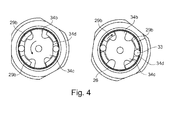
- this jaw coupling piece (or output element) 34 according to the Fig. 4 defines each of the planar surface portions 34d together with the ring gear forming sleeve 26 a circular segment-shaped cavity, in each of which a clamping / rolling element 33 (eg cylindrical clamping body) is inserted.
- the (four) jaws 29b of the second planet carrier (entrainment member) 29 are dimensioned and angularly spaced so that upon active rotation (motor driving) of the planet carrier (entrainment member) 29 against the claws 34b of the output member 34 create and at the same time the rolling elements 33 in Essentially in the middle of the flat surfaces 34d of the output element 34 entrain verklemmungslitis. This condition is especially in the Fig. 4 , right figure shown.
- the output shaft 30 has at its distal end portion a coupling piece 35 which protrudes axially from the cartridge 16 and can be brought into engagement with a mating coupling piece, in particular the chuck unit.
- the gear unit is flanged for operation on the housing of the drilling and / or milling machine, not shown, wherein the input shaft 18 of the gear unit with the (not shown) motor shaft of the machine comes into shaft engagement.
- the output shaft 30 of the gear unit is further rotatably connected to the drive shaft 1 of the chuck unit as described above.
- the drive shaft 1 of the chuck unit must be held stationary while the chuck housing is rotated relative thereto (manually). That is, first, upon manual rotation of the chuck housing for a tool change, a torque (counter to the quiescent motor) is applied to the drive shaft 1 of the chuck unit, which is transmitted to the output member 34 via the output shaft 30 of the gear unit. This therefore rotates slightly substantially without the entrainment of the rolling elements 33, that is, the output member 34 rotates substantially relative to the rolling elements 33.
- the rolling bodies 33 are clamped / clamped between the flat surfaces 34d and the inner wall of the sleeve 26 and the torque transmitted directly via the rolling elements 33 to the transmission housing (cartridge 16). Since the gear housing is non-rotatably flanged with the (not shown) machine housing, a user on the machine housing handle can apply a counter torque, without having to embrace.
- the operation of the described keyless chuck assembly preferably consisting of the chuck unit according to the invention and the gear unit is simple and fast. It allows for precise work, since the user does not have to change the grip of the screwdriver, drill / milling machine when changing a tool. Therefore, a tool change by a single person is possible. It is a firm clamping guaranteed, since the machine and the locking sleeve can be optimally grasped. It also results in greater security to the effect that the tool does not dissolve during operation in the secondary direction of rotation. In combination with the single-jaw chuck mentioned above, this results in a reliable system with low patient risk.
- the surgical screwdriver, drilling or milling machine can also be used in the function of a "conventional", preferably working in both directions by the integrated design of gear unit with Wellenarrettechnik screwdriver.
- a keyless chuck assembly of a medical screwdriver, drill and / or milling machine comprising a chuck unit with a chuck housing in which clamping jaws are axially displaceable by means of a pressure spindle which is in threaded engagement with a drive shaft rotatably mounted in the chuck housing.
- an optionally activatable and / or deactivatable freewheel is provided between the drive shaft and the chuck housing.
- the keyless chuck assembly has a transmission device preferably planetary gear device with integrated shaft lock, which is used or used as an external unit between the screwdriver, drill and / or milling machine (screwdriver machine) and the chuck unit.
Abstract
Description
Die vorliegende Erfindung betrifft eine schlüssellose Spannfutteranordnung einer medizinischen Handbohr-/-fräsmaschine insbesondere gemäß dem Oberbegriff des Patentanspruchs 1.The present invention relates to a keyless chuck arrangement of a medical hand drilling / milling machine, in particular according to the preamble of
Eine medizinische Handbohrmaschine ist ein elektrisches ggf. batteriegetriebenes, oder pneumatisches chirurgisches Instrument, welches beispielsweise zum Ausarbeiten von Montagelöchern in Knochenmaterial zur Fixierung von Implantaten Verwendung findet. In einer solchen Maschine werden spezielle Bohr- und/oder Fräswerkzeuge eingespannt, die auch während des Einsatzes vor Ort immer wieder gewechselt werden müssen. Dazu dienen manuell betätigbare Spann- oder Bohrfutter, deren Konstruktion ein festes Einspannen und Freigeben des Werkzeugs mit oder ohne Zuhilfenahme eines sogenannten Spannschlüssels gestatten. Ältere Maschinen verwenden sogenannte Zahnkranzbohrfutter, bei denen zum Spannen und Öffnen ein Spannschlüssel benötigt wird. Der Vorteil von Zahnkranzbohrfuttern besteht darin, dass Werkzeuge für beide Drehrichtungen (Rechts- und Linkslauf) sicher gespannt werden können. Andererseits sind Spannfutter mit Schlüssel heute aus ergonomischen und arbeitsökonomischen Gründen veraltet. Deshalb kommen heute insbesondere auch schlüssellose Bohr-/Spannfutter zum Einsatz.A medical hand drill is an electrical, possibly battery-powered, or pneumatic surgical instrument, which is used for example for working out mounting holes in bone material for the fixation of implants. In such a machine special drilling and / or milling tools are clamped, which must be changed again and again during use on site. Serve manually operated chuck or chuck whose construction allow a firm clamping and releasing the tool with or without the aid of a so-called Spannschlüssels. Older machines use so-called sprocket chucks, which require a clamping wrench for clamping and opening. The advantage of sprocket chucks is that tools for both directions of rotation (clockwise and anticlockwise) can be safely clamped. On the other hand, chucks with keys are outdated today for ergonomic and labor-economical reasons. That is why keyless drilling / chucks are used in particular today.
Aus dem Stand der Technik beispielsweise gemäß der
Um die Spannfuttereinheit zu öffnen, wird der Griffring mit der einen Hand und das Gehäuse (auch Verschlusshülse genannt) vorzugsweise im Bereich der Spannbacken mit der anderen Hand festgehalten und jeweils entgegengesetzt zueinander (d.h. das Gehäuse gegen den Uhrzeigersinn und der Griffring im Uhrzeigersinn) gedreht. Dadurch wandert die Druckspindel entsprechend der Ganghöhe des Spindelgewindes in die Trägerhülse hinein und zieht dabei die Spannbacken in die gleiche Richtung zurück. Aufgrund der Konizität des vorderen Gehäuseabschnitts und der Führung des Backenträgers bewegen sich die Spannbacken gleichzeitig radial auseinander. Auf diese Weise erweitert sich der von den Spannbacken definierte Aufnahmedurchmesser. Soll die Spannfuttereinheit geschlossen werden, muss lediglich das Gehäuse unter Festhalten des Griffrings nunmehr in Uhrzeigerrichtung gedreht werden, wodurch sich die Druckspindel aus der Trägerhülse heraus bewegt und die Spannbacken vorwärts schiebt. Dabei verengt sich der Aufnahmedurchmesser wieder, wodurch das zuvor eingesteckte Werkzeug eingespannt wird.To open the chuck unit, the handle ring with one hand and the housing (also called closure sleeve) are preferably held in the region of the clamping jaws with the other hand and respectively rotated in opposite directions (i.e., the housing counterclockwise and the handle ring in a clockwise direction). As a result, the pressure spindle moves in accordance with the pitch of the spindle thread into the carrier sleeve and pulls the jaws back in the same direction. Due to the taper of the front housing portion and the guide of the jaw carrier, the jaws move radially apart at the same time. In this way, the recording diameter defined by the clamping jaws expands. If the chuck unit to be closed, only the housing must now be rotated while holding the handle ring now in a clockwise direction, causing the pressure spindle moves out of the carrier sleeve and pushes the jaws forward. In this case, the receiving diameter narrows again, whereby the previously inserted tool is clamped.
Das Spindelgewinde ist so konstruiert, dass es selbsthemmend wirkt. Zudem ist die Gewinderichtung so gewählt, dass im normalen Gebrauch der Maschine, vorliegend eine Rotation im Uhrzeigersinn (Rechtslauf), eine zusätzliche Einspannkraft (-moment) auf die Trägerhülse aufgebracht wird, die ein weiteres Festspannen des Werkzeugs in der Spannfuttereinheit bewirkt. In anderen Worten ausgedrückt, sind schlüssellose Spannfutteranordnungen, welche auf dem vorstehend genannten Druckspindel-Prinzip beruhen, bauartbedingt im Wesentlichen nur für eine Drehrichtung (in der Regel Rechtslauf-Betrieb) geeignet. Ist die schlüssellose Spannfutteranordnung zweihülsig, d.h. bestehend aus Gehäuse (oder Verschlusshülse) und Griffring ausgeführt, ist das Handling beim Spannen und Öffnen zudem immer noch sehr umständlich. Der Benutzer benötigt nämlich in diesem Fall beide Hände an der Spannfutteranordnung für das gegeneinander Drehen von Gehäuse und Griffring, wobei er gleichzeitig aber auch noch die Maschine (einschließlich Motor) irgendwie halten muss.The spindle thread is designed to be self-locking. In addition, the thread direction is selected so that in normal use of the machine, in this case a clockwise rotation (clockwise), an additional clamping force (-moment) is applied to the support sleeve, which causes a further tightening of the tool in the chuck unit. In other words, keyless chuck arrangements, which are based on the abovementioned pressure spindle principle, are suitable for design reasons essentially only for one direction of rotation (generally clockwise operation). If the keyless chuck arrangement is two-sleeve, ie consisting of housing (or closure sleeve) and handle ring, the handling during clamping and opening is still very cumbersome. The user needs in this case both hands on the chuck assembly for the against each other turning the housing and handle ring, while at the same time he still has to hold the machine (including motor) somehow.
Trotz dieser Schwierigkeiten hat die schlüssellose Spannfutteranordnung gegenüber einem altbekannten Zahnkranzbohrfutter den großen Vorteil, dass zum Spannen und Lösen kein externes Bedienerwerkzeug erforderlich ist, welches für einen Patienten sogar eine Gefahr darstellen kann, wie dies nachstehend kurz erläutert wird.Despite these difficulties, the keyless chuck assembly over a well-known sprocket chuck has the great advantage that for clamping and loosening no external operator tool is required, which may even pose a danger to a patient, as will be explained briefly below.
Bei chirurgischen Eingriffen ist die Spannfuttereinheit an die Bohr- und Fräsmaschine angekuppelt. Während einer Operation ist es aber häufig notwendig, dass die Werkzeuge mehrmals gewechselt werden müssen. Es kann auch vorkommen, dass ein Werkzeug im OP-Situs verbleibt und später wieder aufgenommen wird. Dies erfordert ein wiederholtes Spannen und Lösen der Spannfuttereinheit. Bei diesem Vorgang wird die nachteilige Handhabung eines Zahnkranzbohrfutters erkennbar. Ist nämlich ein Spannschlüssel erforderlich, muss zum Einen die Bohr- und Fräsmaschine und zum Anderen der Spannschlüssel gehalten und gedreht werden. Während des Hantierens mit dem Spannschlüssel werden Maschine und Werkzeug unvermeidbar geschwenkt und gekippt, sodass das ausgearbeitete Montageloch in dem das Werkzeug ggf. noch steckt, ausbrechen kann.For surgical procedures, the chuck unit is coupled to the drilling and milling machine. During an operation, however, it is often necessary that the tools must be changed several times. It may also happen that a tool remains in the surgical site and is resumed later. This requires repeated cocking and loosening of the chuck unit. In this process, the adverse handling of a Zahnkranzkhrfutters can be seen. If a wrench is required, on the one hand, the drilling and milling machine and, on the other hand, the wrench must be held and turned. While handling the clamping wrench machine and tool are inevitably pivoted and tilted, so that the elaborate mounting hole in which the tool may still be infected, break out.
Im Fall einer schlüssellosen Spannfutteranordnung verbessert sich zwar diese Situation, aber auch hier müssen zumindest Gehäuse und Haltering zumindest nach derzeitigem Stand der Technik gegeneinander verdreht werden, was mit zwei Händen ebenfalls schwierig ist. Insofern ist auch das Handling der bekannten schlüssellosen Spannfutteranordnung unbefriedigend.In the case of a keyless chuck arrangement, although this situation improves, but also at least housing and retaining ring must be rotated against each other at least according to the current state of the art, which is also difficult with two hands. In this respect, the handling of the known keyless chuck arrangement is unsatisfactory.
Ein anderes Problem besteht darin, dass beispielsweise zum Linksgewinde schneiden, Herausdrehen von Schrauben, etc. ein Linkslauf erforderlich ist. Eine schlüssellose Spannfutteranordnung (-einheit) beispielsweise der Drei-Backen-Bauart mit Druckspindel kann sich aber im Linkslauf öffnen. Geschieht dies während einer Operation, kann das Werkzeug im Knochen stecken bleiben. Um dieses dann wieder zu bergen, werden meistens zwei Personen benötigt. Die eine Person muss die Maschine genau über dem stecken gebliebenen Werkzeug ausrichten und die andere Person muss das Werkzeug erneut einspannen. Dies kostet Zeit und erhöht das Operationsrisiko für den Patienten.Another problem is that, for example, to cut left-hand thread, unscrewing screws, etc. a reverse rotation is required. However, a keyless chuck arrangement (unit), for example, the three-jaw design with pressure spindle can open in reverse. If this happens during an operation, the tool can get stuck in the bone. To recover this then usually two people are needed. One person has to align the machine just above the stuck tool and the other person must re-clamp the tool. This takes time and increases the surgical risk for the patient.
Angesichts dieser komplexen Problematik des Stands der Technik ist es die Aufgabe der vorliegenden Erfindung, eine schlüssellose Spannfutteranordnung (-einheit) einer Schraub-, Bohr- und/oder Fräsmaschine vorzugsweise der Handmaschinenbauart bereit zu stellen, die eine höhere Funktionalität aufweist. Ein Ziel ist es, die gattungsgemäße Maschine sowohl rechts- als auch linksläufig sicher einsetzen zu können. Ein weiteres Ziel ist es, den Spannvorgang zu vereinfachen und so einen Werkzeugwechsel auch von einer Person problemlos durchführbar zu machen.In view of this complex problem of the prior art, it is the object of the present invention to provide a keyless chuck arrangement (unit) of a screwing, drilling and / or milling machine, preferably of the hand-held type, having a higher functionality. One goal is to be able to use the generic machine both right and left safe. Another goal is to simplify the clamping process and to make a tool change by one person easily feasible.
Die vorstehend genannte Aufgabe wird durch eine schlüssellose Spannfutteranordnung (-einheit) vorzugsweise mit drei Spannbacken und Druckspindelprinzip mit den Merkmalen des Anspruchs 1 gelöst. Vorteilhafte Ausgestaltungen der Erfindung sind Gegenstand der Unteransprüche.The above object is achieved by a keyless chuck arrangement (unit) preferably with three jaws and pressure spindle principle with the features of
Der Grundgedanke der Erfindung besteht demzufolge darin, durch Anordnung einer bei einer Drehrichtung entgegen der vorbestimmten Hauptdrehrichtung wirkenden sowie vorzugsweise manuell oder automatisch einrückenden Bremse (oder Sperrkupplung) ein Verdrehen des Druckspindelantriebs bezüglich des Spannfuttergehäuses (bzw. der Verschlusshülse) für ein unbeabsichtigtes Öffnen der Spannfutteranordnung zu blockieren. Ein anderer oder zusätzlicher Grundgedanke der Erfindung besteht in der Vorschaltung eines Über- oder Untersetzungsgetriebes (Vorgelege) mit integrierter Wellenarretierung, wodurch die Anordnung eines Griff-/Halterings auf der Antriebswelle überflüssig wird. In diesem Fall kann nämlich ein Gegendrehmoment zum manuell an die Verschlusshülse angelegten Öffnungsmoment über das Gehäuse der Bohr- und/oder Fräsmaschine aufgebracht werden, sodass ein Umgreifen vom Maschinengriff auf den (nicht mehr vorhandenen) Haltering entfällt.The basic idea of the invention therefore consists in providing a rotation of the pressure spindle drive with respect to the chuck housing (or the closure sleeve) by unintentionally opening the chuck arrangement by arranging a brake (or blocking clutch) which acts in a direction of rotation against the predetermined main direction of rotation and preferably manually or automatically To block. Another or additional basic idea of the invention consists in the connection of an over or reduction gear (countershaft) with integrated shaft lock, whereby the arrangement of a grip / retaining ring on the drive shaft is superfluous. In this case, namely, a counter-torque for manually applied to the closure sleeve opening torque can be applied through the housing of the drilling and / or milling machine, so that encompassing the machine handle on the (no longer existing) retaining ring deleted.
Ein konkreter Aspekt der Erfindung sieht demzufolge die Bereitstellung einer (vorzugsweise) schlüssellosen Spannfutteranordnung einer medizinischen Bohr-und/oder Fräsmaschine vorzugsweise in der Form einer Spannfuttereinheit vor, mit einem Spannfuttergehäuse, in dem (weiter vorzugsweise drei) Spannbacken mittels einer Druckspindel axialverschiebbar sind, die mit einer im Spannfuttergehäuse drehbar gelagerten Antriebswelle der Spannfuttereinheit in Gewinde- bzw. Spindeleingriff steht. Erfindungsgemäß ist ein wahlweise (vorzugsweise manuell oder automatisch) aktivier-und/oder deaktivierbarer Freilauf (als die Bremse oder Sperrkupplung) zwischen der Antriebswelle und dem Spannfuttergehäuse eingebaut. Der Freilauf wird (manuell oder automatisch) aktiviert, wenn ein Bohr- und/oder Fräsbetrieb aufgenommen wird. In diesem Fall erlaubt der Freilauf bei einem Betrieb in Hauptdrehrichtung, z.B. Rechtslauf, ein weiteres Festziehen der Spannfuttereinheit in Übereinstimmung mit dem Stand der Technik. Im Unterschied hierzu blockiert jedoch der Freilauf eine Relativbewegung zwischen Spannfuttergehäuse und Antriebswelle für ein ungewolltes Öffnen/Lockern der Spannfuttereinheit im Fall eines gegenläufigen Betriebs in Nebendrehrichtung, z.B. Linkslauf. Soll die Spannfuttereinheit geöffnet werden, wird hierfür der Freilauf (manuell oder automatisch) deaktiviert, sodass eine Relativdrehbewegung der Antriebswelle bezüglich des Gehäuses entgegen der Hauptdrehrichtung ermöglicht wird.A concrete aspect of the invention accordingly provides for the provision of a (preferably) keyless chuck assembly of a medical drilling and / or milling machine, preferably in the form of a chuck unit, with a chuck housing in which (more preferably three) clamping jaws are axially displaceable by means of a pressure spindle, which is in threaded or spindle engagement with a drive shaft of the chuck unit rotatably mounted in the chuck housing. According to the invention, an optional (preferably manually or automatically) activatable and / or deactivatable freewheel (as the brake or lock-up clutch) is installed between the drive shaft and the chuck housing. The freewheel is activated (manually or automatically) when a drilling and / or milling operation is started. In this case, the freewheel allows a further tightening of the chuck unit in accordance with the prior art when operating in the main direction of rotation, for example clockwise rotation. In contrast, however, the freewheel blocks a relative movement between chuck housing and drive shaft for accidental opening / loosening of the chuck unit in the case of an opposite operation in the secondary direction, for example, anti-clockwise rotation. If the chuck unit is to be opened, the freewheel (manually or automatically) is deactivated for this purpose so that a relative rotational movement of the drive shaft relative to the main direction of rotation with respect to the housing is made possible.
Vorteilhaft ist es hierbei, wenn zwischen dem Freilauf und dem Spannfuttergehäuse oder zwischen dem Freilauf und der Antriebwelle eine vorzugsweise manuell (oder automatisch) betätigbare Kupplung angeordnet ist. Über diese kann der Freilauf dem (über die Spannbacken geführten) Drehmomentfluss optional für dessen Aktivierung parallel geschaltet werden. Alternativ ist es aber auch möglich, eine derartige Kupplung beispielsweise mit dem Wahlschalter für Rechts-/Linkslauf zu koppeln und den Freilauf quasi automatisch erst dann zu aktivieren, wenn der Wahlschalter aus der Hautdrehrichtungsposition (z. B. Rechtslauf) in die Nebendrehrichtungsposition (z.B. Linkslauf) umgeschaltet wird. Schließlich besteht die Möglichkeit einer vollautomatischen Kupplung, welche bei (motorisiertem) Antreiben der Spannfuttereinheit (beispielsweise mit Betätigen des Motor-Startschalters) den Freilauf aktiviert.It is advantageous here if between the freewheel and the chuck housing or between the freewheel and the drive shaft, a preferably manually (or automatically) operable clutch is arranged. This allows the freewheel to be connected in parallel with the torque flow (guided via the clamping jaws) as an option for its activation. Alternatively, it is also possible to couple such a clutch, for example, with the selector switch for clockwise / anticlockwise rotation and quasi automatically activate the freewheel only when the selector switch from the Hautdrehrichtungsposition (eg clockwise rotation) in the secondary rotation direction (eg counterclockwise ) is switched. Finally, there is the possibility of a fully automatic clutch, which activates the freewheel when (motorized) driving the chuck unit (for example, with actuation of the engine start switch).
Gemäß einem anderen oder zusätzlichen Aspekt der Erfindung ist der Freilauf ein auf der Antriebswelle oder im Spannfuttergehäuse reibschlüssig fixierbarer Hülsenfreilauf und die Kupplung ein zwischen den Hülsenfreilauf und das Spannfuttergehäuse oder zwischen den Hülsenfreilauf und die Antriebswelle axial einschiebbares Drehmoment-Übertragungsbauteil, über das die reibschlüssige Fixierung des Hülsenfreilaufs aktiviert werden kann. Vorteilhaft ist es hierbei, wenn das Drehmoment-Übertragungsbauteil ein Formschlusselement, beispielsweise ein (Nut-und) Federelement oder eine den Hülsenfreilauf umgreifende sowie diesen fest aufnehmende sowie mit der Antriebswelle oder dem Spannfuttergehäuse formschlüssig gekoppelte Schiebehülse ist, wobei das Formschlusselement weiter vorzugsweise in Axialrichtung der Antriebswelle zwischen einer Eingriffs- und Freigabeposition des Hülsenfreilaufs hin- und herbewegbar ist.According to another or additional aspect of the invention, the freewheel on the drive shaft or in the chuck housing frictionally fixable sleeve freewheel and the clutch between the sleeve freewheel and the chuck housing or between the sleeve freewheel and the drive shaft axially insertable torque transmission component, via which the frictional locking of the sleeve freewheel can be activated. It is advantageous in this case if the torque-transmitting component is a form-locking element, for example a (tongue and) spring element or a sleeve freewheel encompassing and this firmly receiving and with the drive shaft or the chuck housing positively coupled sliding sleeve, wherein the positive locking element further preferably in the axial direction of Drive shaft between an engagement and release position of the sleeve freewheel back and forth.
Vorteilhaft ist es hierbei, wenn der Hülsenfreilauf zusammen (quasi einstückig) mit dem Drehmoment-Übertragungsbauteil verschoben wird, um so in die bzw. aus der vorstehend genannten Reibschlussposition zu kommen, während der Formschluss des Drehmoment-Übertragungsbauteils permanent beibehalten bleibt. Ein solcher rein mechanischer Aufbau ist einfach in seiner Funktion und damit vergleichsweise robust und wenig störanfällig. Auch ist seine Handhabung unkompliziert und übersichtlich, sodass das Risiko einer Fehlbedienung während der Operation gering ist. Auch wird das Aktivieren und Deaktivieren des Freilaufs (infolge der Reibschlussverbindung) unabhängig von der Drehposition der Antriebswelle relativ zum Spannfuttergehäuse, sodass ein Verklemmen der Kupplung bei deren Betätigung ausgeschlossen ist.It is advantageous in this case if the sleeve freewheel is moved together (quasi in one piece) with the torque-transmitting component, so as to come into or out of the above-mentioned frictional engagement position, while the form fit of the torque-transmitting component is permanently maintained. Such a purely mechanical structure is simple in its function and thus relatively robust and less prone to failure. Also, its handling is straightforward and clear, so that the risk of incorrect operation during the operation is low. Also, the activation and deactivation of the freewheel (due to the frictional engagement) is independent of the rotational position of the drive shaft relative to the chuck housing, so that jamming of the clutch is excluded when actuated.
Weiter vorteilhaft ist es, wenn die Schiebehülse einen Rastvorsprung oder Rastrücksprung hat, der mit einem entsprechenden Gegenstück (bestehend aus zwei axial beabstandeten Rücksprüngen oder Vorsprüngen) auf Seiten der Antriebswelle oder des Spannfuttergehäuses zusammenwirkt, um dadurch zwei Rastpositionen festzulegen, von denen die eine Rastposition eine Reibschlussstellung für ein Aktivieren des Freilaufs (Eingriffsposition) und die andere Rastposition eine Gleit- bzw. Durchrutschstellung für ein Deaktivieren des Freilaufs (Freigabeposition) definiert. Durch diese Rastung wird dem Bediener das korrekte Einnehmen der gewählten Stellung (haptisch und ggf. akustisch) signalisiert, wodurch die Bedienbarkeit verbessert wird.It is further advantageous if the sliding sleeve has a latching projection or catch recess which cooperates with a corresponding counterpart (consisting of two axially spaced recesses or projections) on the side of the drive shaft or the chuck housing, thereby defining two latching positions, one of which is a latching position Frictionally closed position for activating the freewheel (engagement position) and the other detent position defines a sliding or slip position for deactivating the freewheel (release position). By this latching the operator the correct ingestion of the selected position (haptic and possibly acoustic) is signaled, whereby the operability is improved.
Eine Variante sieht hierbei vor, die Schiebehülse manuell zu betätigen. Es ist aber auch möglich, die Schiebehülse in einer spiralförmigen Kulisse an der Umfangsseite der Antriebswelle zu führen, sodass eine Drehung der Antriebswelle zwangsläufig in einer Axialverschiebung der Schiebehülse resultiert. Unabhängig davon kann die Schiebehülse aber auch elektrisch/elektromagnetisch betätigt werden.A variant provides in this case to operate the sliding sleeve manually. But it is also possible, the sliding sleeve in a spiral backdrop on the peripheral side of To drive shaft, so that rotation of the drive shaft inevitably results in an axial displacement of the sliding sleeve. Regardless, the sliding sleeve can also be operated electrically / electromagnetically.
Ein anderer oder zusätzlicher Aspekt der Erfindung sieht die Anordnung einer Getriebeeinrichtung mit integrierter (automatisch wirkender) Wellenarretierung vor, die als externe (separate) Einheit der vorstehend beschriebenen Spannfuttereinheit vorgeschaltet bzw. vorschaltbar ist, d.h. die zwischen eine Abtriebswelle der Bohr-und/oder Fräsmaschine und die Antriebswelle im Spannfuttergehäuse wahlweise einsetzbar oder eingesetzt ist. Die Getriebeeinrichtung bzw. -einheit übernimmt somit zwei Funktionen, nämlich das Über-/Untersetzen der von der Bohr- und/oder Fräsmaschine erzeugten Drehzahl in eine werkzeugspezifische Drehzahl und das Festhalten der Antriebswelle im Spannfuttergehäuse während des manuellen Spannens oder Lösens der Spannfuttereinheit als Ersatz für einen (dann) nicht mehr notwendigen Haltering, wie er aus dem Stand der Technik bekannt ist.Another or additional aspect of the invention provides for the provision of a transmission device with integrated (self-acting) shaft lock which is preconnected as an external (separate) unit to the above-described chuck unit, i. which is optionally used or inserted between an output shaft of the drilling and / or milling machine and the drive shaft in the chuck housing. The transmission device or unit thus assumes two functions, namely the over / under setting of the speed generated by the drilling and / or milling machine in a tool-specific speed and the retention of the drive shaft in the chuck housing during manual clamping or loosening the chuck unit as a substitute for a (then) no longer necessary retaining ring, as it is known from the prior art.
Eine vorteilhafte Ausgestaltung der Erfindung sieht hierfür vor, dass die Getriebeeinrichtung bzw. -einheit eine in einem Getriebegehäuse gelagerte Eingangswelle hat, die über einen Zahnrad-Getriebezug ein erstes Klauenkupplungsstück (Mitnahmeelement) antreibt, das mit einem zweiten Klauenkupplungsstück (Abtriebselement) in Kupplungseingriff steht, welches auf einer im Getriebegehäuse gelagerten Ausgangswelle der Getriebeeinrichtung drehfest sitzt oder einstückig mit dieser ausgebildet ist. Weiter vorteilhaft ist es, wenn das zweite Klauenkupplungsstück in Umfangsabschnitten zwischen seinen axial vorragenden Klauen (weitgehend plane) Umfangsflächen (Klemmflächen) ausbildet, die zwischen sich und einer Innenwand des Getriebegehäuses jeweils einen im Querschnitt vorzugsweise kreissegmentförmigen Aufnahmeraum definieren, in den jeweils ein Wälzkörper eingesetzt ist, der sich bei einer aktiven (vorzugsweise manuellen) Verdrehung des zweiten Klauenkupplungsstücks relativ zum Getriebegehäuse zwischen der jeweiligen planen Umfangsfläche und der Innenwand verspannt. D.h. die Klauenkupplung hat oder ist gleichzeitig die Wellenarretierung, die dann, wenn das zweite Klauenkupplungsstück aktiv, d. h. bei einem manuellen Verdrehen des Spannfuttergehäuses beispielsweise für ein Lösen (aber auch Verspannen) der Spannfuttereinheit gedreht wird, genau diese Drehung unmittelbar auf das Gehäuse der Getriebeeinheit überträgt, das wiederum mit dem Gehäuse der Bohr- und/oder Fräsmaschine fest verbunden ist. Mit Festhalten des Maschinengehäuses an einem dafür vorgesehenen Maschinengriff, wird somit gleichzeitig auch die Klauenkupplung und damit die Antriebswelle der Spannfuttereinheit festgehalten.An advantageous embodiment of the invention provides for this, that the transmission device or unit has a mounted in a transmission housing input shaft which drives via a gear-Zahnradzug a first jaw coupling piece (driving element), which is in coupling engagement with a second jaw coupling piece (output member), which is rotatably seated on an output shaft of the transmission device mounted in the transmission housing or formed integrally therewith. It is further advantageous if the second jaw coupling piece forms (largely plane) peripheral surfaces (clamping surfaces) in peripheral sections between its and an inner wall of the gear housing, each defining a preferably circular-segment-shaped receiving space into which a respective rolling body is inserted which braces in an active (preferably manual) rotation of the second jaw coupling piece relative to the transmission housing between the respective planar peripheral surface and the inner wall. That is, the jaw clutch has or is at the same time the shaft lock, which, when the second jaw coupling piece active, ie, for a manual twisting of the chuck housing, for example, for a release (but also clamping) of the Chuck unit is rotated, exactly this rotation transmits directly to the housing of the gear unit, which in turn is firmly connected to the housing of the drilling and / or milling machine. By holding the machine housing to a designated machine handle, thus simultaneously the jaw clutch and thus the drive shaft of the chuck unit is held.
Eine weitere oder andere vorteilhafte Weiterbildung sieht vor, dass das erste Klauenkupplungsstück axial vorragende Klauen hat, die so dimensioniert sind, dass sie bei einer aktiven Verdrehung des ersten Klauenkupplungsstücks relativ zum Getriebegehäuse (d.h. bei regulärem, motorisiertem Betreiben der Schraub-, Bohr-und/oder Fräsmaschine) für ein Antreiben des zweiten Klauenkupplungsstücks die Wälzkörper mitnehmen, um deren Verspannen zwischen der jeweiligen planen Umfangsfläche (oder Klemmfläche) und der Innenwand des Getriebegehäuses zu vermeiden. In diesem Fall ist die Wellenarretierung inaktiv und eine leichtgängige Drehung der Klauenkupplung möglich.A further or other advantageous development provides that the first jaw coupling piece has axially projecting jaws which are dimensioned so that they can be moved relative to the gearbox housing during an active rotation of the first jaw coupling piece (ie during regular, motorized operation of the screwdriving, drilling and / or or milling machine) for driving the second jaw coupling piece, the rolling elements take along to avoid their distortion between the respective planar peripheral surface (or clamping surface) and the inner wall of the transmission housing. In this case, the shaft lock is inactive and a smooth rotation of the dog clutch possible.
Ein anderer oder zusätzlicher Aspekt der Erfindung sieht vor, dass der Zahnrad-Getriebezug ein Planetengetriebe, vorzugsweise der Doppelplanetengetriebebauart (zweistufiges Planetengetriebe) ist mit einem (einzigen) Hohlrad (-element), das büchsenförmig in das Getriebegehäuse drehfest eingesetzt ist und gleichzeitig die (Gehäuse-) Innenwand für die Wälzkörper bildet. Dies hat den Vorteil, dass die Klemmkraft ausgehend von den Wälzkörpern in das Hohlradmaterial eingeleitet wird, das aus einem speziellen Lager-Material und/oder gehärtet ist und damit diesen (linienförmig) von den Wälzkörpern aufgebrachten Klemmkräften standhalten kann. Da das Hohlrad über eine große Fläche mit dem eigentlichen Getriebegehäuse Kontakt hat, können so die punktuellen Klemmkräfte gut in das Getriebegehäuse flächig verteilt werden. Dieses wird daher weniger belastet und kann demzufolge aus einem leichteren/weniger belastbaren Material hergestellt sein.Another or additional aspect of the invention provides that the gear train is a planetary gear, preferably the double planetary gear (two-stage planetary gear) with a (single) ring gear (-element), which is sleeve-shaped in the gear housing rotatably inserted and simultaneously the (housing -) forms inner wall for the rolling elements. This has the advantage that the clamping force is introduced from the rolling elements in the Hohlradmaterial, which is made of a special bearing material and / or cured and thus can withstand (linearly) applied by the rolling elements clamping forces. Since the ring gear has contact with the actual gearbox housing over a large area, the punctiform clamping forces can be distributed over the entire surface of the gearbox housing. This is therefore less burdened and can therefore be made of a lighter / less resilient material.
Abschließend sei darauf hingewiesen, dass die Merkmale gemäß der vorstehend genannten Aspekte der Erfindung individuell die gestellte Aufgabe lösen bzw. einen Beitrag zur Lösung der Aufgabe leisten und daher separat oder in Kombination miteinander beanspruchbar sind.Finally, it should be noted that the features according to the abovementioned aspects of the invention individually solve the stated problem or contribute to the solution of the problem and therefore can be claimed separately or in combination with each other.
Die Erfindung wird nachstehend anhand eines bevorzugten Ausführungsbeispiels unter Bezugnahe auf die begleitenden Figuren näher beschrieben.
-
Fig. 1 zeigt den Längsschnitt einer Spannfutteranordnung und insbesondere einer separaten (individuellen) Spannfuttereinheit der Spannfutteranordnung gemäß dem bevorzugten Ausführungsbeispiel der Erfindung, -
Fig. 2 zeigt den Längsschnitt einer separaten (individuellen) Getriebeeinheit mit integrierter Wellenarretierung der Spannfutteranordnung gemäß dem bevorzugten Ausführungsbeispiel der Erfindung, -
Fig. 3 zeigt eine Explosionsdarstellung der Wellenarretierung gemäßFig. 2 und -
Fig. 4 zeigt einen Querschnitt der Wellenarretierung gemäß derFig. 2 und3 in gelöster (inaktiver) Stellung (rechte Abbildung) und in arretierter/verspannter (aktiver) Stellung (linke Abbildung).
-
Fig. 1 shows the longitudinal section of a chuck assembly and in particular a separate (individual) chuck unit of the chuck assembly according to the preferred embodiment of the invention, -
Fig. 2 shows the longitudinal section of a separate (individual) gear unit with integrated shaft lock the chuck assembly according to the preferred embodiment of the invention, -
Fig. 3 shows an exploded view of the shaft lock according toFig. 2 and -
Fig. 4 shows a cross section of the Wellenarretierung according to theFig. 2 and3 in released (inactive) position (right figure) and in locked / strained (active) position (left figure).
In der
In einem distalen, der Schraub-/Bohr-/Fräsmaschine abgewandten, jedoch noch innerhalb der Mantelhülse 2 liegenden Endabschnitt hat die Antriebswelle 1 ein inneres Spindelgewinde, in das eine Druckspindel 4 axialseitig eingedreht ist. Die Druckspindel 4 ist an ihrem dem Spindelgewinde abgewandten Ende in einem Backenträger 5 axialverschiebbar, der in die Mantelhülse 2 an deren distaler Stirnseite eingesetzt und mittels einer Anzahl von radialen Bolzen/Stiften 7 darin fixiert ist.In a distal, the screwing / drilling / milling machine facing away, but still within the
Der Backenträger 5 ist an seinem distalen Endabschnitt konisch geformt und weist axial sich erstreckende Führungsnuten und/oder Schienen auf (nicht im Einzelnen gezeigt), an denen platten/plättchenartige Spannbacken 6 (vorzugsweise drei Spannbacken 6) axialverschiebbar gehalten sind. Die der Druckspindel 4 jeweils zugewandten (schmalen) Stirnkanten der Spannbacken 6 stützen sich axial auf der Stirnseite der Druckspindel 4 ab, die hierfür nicht weiter dargestellte Radialnuten aufweist, in denen die Spannbacken 6 radial gleitfähig gehalten sind. Dabei bildet der Backenträger 5 an seinem proximalen Axialabschnitt einen radial umlaufenden äußeren Vorsprung (Ringvorsprung) aus, der zum Einen als Axialflansch gegenüber der Mantelhülse 2 und zum Anderen als axialer Endanschlag zum Begrenzung der Axialbewegung der Spannbacken 6 für ein Öffnen der Spannfuttereinheit dient.The
Der am distalen Endbereich konusförmig sich verjüngende Backenträger 5 ist ferner in diesem Axialabschnitt von einer Verschlusshülse 8 umgeben, die fest mit der Mantelhülse 2 verschraubt oder anders fest verbunden ist und somit zusammen mit der Mantelhülse 2 das Spannfuttergehäuse der Spannfuttereinheit bildet.The
Am proximalen Endabschnitt des Spannfuttergehäuses ist eine wahlweise ein-/ausrückbare Kupplungseinrichtung vorzugsweise in Form eines Freilaufs angeordnet.At the proximal end portion of the chuck housing an optional on / disengageable coupling device is preferably arranged in the form of a freewheel.
Diese besteht aus einem schaltbaren Drehmoment-Übertragungsbauteil vorliegend eine Schiebehülse 9, die axialverschieblich auf der Antriebswelle 1 und/oder in der Mantelhülse 2 gehalten ist, derart, dass sie eine vorbestimmte, durch Rast- oder Anschlagspositionen festgelegte Axialstrecke in die und aus der Mantelhülse 2 verschiebbar ist.This consists of a switchable torque-transmitting component present a sliding
Zwischen der Schiebehülse 9 und der Antriebswelle 1 ist ein Hülsenfreilauf 10 eingesetzt. Der Hülsenfreilauf 10 ist hierfür außenumfangsseitig in die Schiebehülse 9 reib- und/oder formschlüssig fest eingepresst oder eingesetzt, um sich gemeinsam (einstückig) mit dieser axial verschieben zu können. Die radiale Innenseite des Freilaufs 10 ist axial gleitend auf der Mantelfläche der Antriebswelle 1 geführt.Between the sliding
Je nach Axialposition der Schiebehülse 9 geht der Freilauf 10 eine maßgeblich in Umfangsrichtung wirkende Reibschlussverbindung mit der Antriebswelle 1 ein. Dies kann z. B. dadurch bewirkt werden, indem die Antriebswelle 1 außenumfangsseitig im Bereich des axialen Schiebewegs der Schiebehülse 9 konisch sich aufweitend ausgebildet ist, sodass der Freilauf 10 schiebewegabhängig auf der Antriebswelle 1 reibschlüssig aufsitzt bzw. sich von dieser löst. Die Schiebehülse 9 hat an ihrem Außenumfang eine oder mehrere Axialnuten oder eine Nut- und Federanordnung, um mit der radialen Innenseite der Mantelhülse 2 einen in Umfangsrichtung wirkenden, jedoch eine Axialverschiebung erlaubenden Formschluss einzugehen.Depending on the axial position of the sliding
Alternativ zu dieser in
Entscheidend bei der Freilaufkonstruktion ist, dass der Hülsenfreilauf 10 zumindest mit der Antriebswelle 1 oder der Mantelhülse 2 einen Axialpositionsabhängigen Reibschluss eingeht und vorzugsweise mit dem jeweils anderen Bauteil, nämlich der Mantelhülse 2 oder der Antriebswelle 1 einen permanenten Formschluss in Umfangsrichtung hat. Dadurch wird das Aktivieren und Deaktivieren des Freilaufs unabhängig von der Relativ-Drehposition der Antriebswelle 1 zur Mantelhülse 2.Crucial in the freewheel design is that the
Wie in der
Die eine Endposition, definiert durch eine Welleneindrehung, bestimmt somit die maximal aus der Mantelhülse 2 ausgefahrene Position der Schiebehülse 9, in der kein Reibschluss möglich ist und der Freilauf somit deaktiviert wird, wohingegen die andere Endposition, definiert durch die andere Welleneindrehung, die maximal in die Mantelhülse 2 eingefahrene Position der Schiebehülse 9 bestimmt, in der ein maximaler Reibschluss erreicht wird und der Freilauf folglich aktiviert ist.The one end position, defined by a shaft rotation, thus determines the maximum extended from the
Abschließend sei noch darauf verwiesen, dass die Antriebswelle 1 an ihrem proximalen, aus der Mantelhülse 2 herausragenden Endabschnitt mit einem Innengewinde 15 versehen ist, in das eine weitere Antriebswelle (in der
Die Funktionsweise der Spannfuttereinheit als ein (individueller) Bestandteil der erfindungsgemäßen Spannfutteranordnung soll nachfolgend erläutert werden.The operation of the chuck unit as an (individual) component of the chuck assembly according to the invention will be explained below.
Für das Einsetzen eines Werkzeugs, z.B. ein Bohrer oder Fräser, muss zunächst die von den Spannbacken 6 bestimmte "Schlüsselweite" vergrößert werden. Zu diesem Zweck wird zunächst die Schiebehülse 9 aus der Mantelhülse 2 axial herausgezogen und somit der Reibschluss zwischen dem Freilauf 10 und der Antriebswelle 1 unterbrochen. In dieser Position ist der Freilauf demnach inaktiv geschaltet, sodass die Antriebswelle 1 gegenüber der Mantelhülse 2 auch in Sperrrichtung des Freilaufs 10 gedreht werden kann. Nun wird die Antriebswelle 1 festgehalten (entweder manuell über den Haltering oder automatisch über eine integrierte Wellenarretierung) und das Spannfuttergehäuse in die Richtung gedreht, die ein Einschrauben der Druckspindel 4 in die Antriebswelle 1 bewirkt. Dabei werden die Spannbacken 6 kontinuierlich längs des Backenträgers 5 zurückgezogen und bewegen sich dabei gleichzeitig infolge der Konizität des Backenträgers 5 und der Verschlusshülse 8 radial auseinander.For inserting a tool, e.g. a drill or cutter, the first of the
Soll ein eingesetztes Werkzeug zwischen den Spannbacken 6 eingespannt werden, muss bei festgehaltener Antriebswelle 1 das Spannfuttergehäuse (an der Verschlusshülse 8) in jene Richtung gedreht werden, die ein Ausdrehen der Druckspindel 4 aus der Antriebswelle 1 bewirkt, wodurch die Spannbacken 6 kontinuierlich unter Einengung der "Schlüsselweite" längs des Backenträgers verschoben werden, solange, bis eine ausreichende radiale Spannkraft auf das Werkzeug aufgebracht ist. Schließlich wird die Schiebehülse 9 in die Mantelhülse 2 axial eingeschoben und dabei zur Aktivierung des Freilaufs 10 ein Reibschluss zwischen dem Hülsenfreilauf 10 und der Antriebswelle 1 hergestellt.If an inserted tool between the
Im Betrieb bei einer Betätigung in Hauptdrehrichtung (z.B. Rechtslauf) bringt die Antriebswelle 1 über die Druckspindel 4 und die Spannbacken 6 ein Drehmoment auf das Werkzeug auf, das in eine Richtung wirkt, in der die Druckspindel 4 aus der Antriebswelle 1 herausgedreht wird. Da der Freilauf 10 in diese Richtung ein Verdrehen zwischen Antriebswelle 1 und Spannfuttergehäuse erlaubt, bewirkt dies ein weiteres Festziehen der Spannbacken 6. Bei einer Betätigung in Nebendrehrichtung (z.B. Linkslauf) würde dies hingegen bedeuten, dass die Antriebswelle 1 über die Druckspindel 4 und die Spannbacken 6 ein Drehmoment auf das Werkzeug aufbringt, das in eine Richtung wirkt, in der die Druckspindel 4 in die Antriebswelle 1 hineingedreht wird. Da der Freilauf 10 in diese Richtung jedoch ein Verdrehen zwischen Antriebswelle 1 und Spannfuttergehäuse sperrt, wird der Drehmomentfluss in diesem Fall parallel zu der Druckspindel 4 von der Antriebswelle 1 über den Freilauf 10 und das Spannfuttergehäuse in den Backenträger 5 und von dort in die Spannbacken 6 geführt. Dies bewirkt zwar kein weiteres Festziehen der Spannbacken 6, aber auch kein Lösen der Spannbacken 6. Damit wird die schlüssellose Spannfuttereinheit gemäß dem bevorzugten Ausführungsbeispiel der Erfindung für den Betrieb in Nebendrehrichtung gemäß vorstehender Definition tauglich.In operation in an operation in the main direction of rotation (eg clockwise rotation) brings the
In den
Insbesondere gemäß der
Innerhalb des Montageflansches 17 ist eine Eingangswelle 18 über Kugellager 19 drehbar gelagert, die mittels Wellenringe 20 axial gesichert sind. Die Eingangswelle 18 hat an ihrem proximalen Ende eine Wellenkupplung 21, die mit der Abtriebswelle der Maschine in Dreheingriff bringbar ist. An dem distalen Ende der Eingangswelle 18 ist ein Zahnrad 22 fixiert oder ausgebildet, welches das Eingangselement eines Zahnradgetriebes, vorliegend z.B. ein Doppelplanetengetriebe (zweistufiges Planetengetriebe) darstellt.Within the mounting
Im Konkreten ist an der Eingangswelle 18 ein erstes Sonnenrad 22 drehfest fixiert, das mit ersten Planetenrädern 23 kämmt, die an einem ersten drehbaren Planetenradträger 24 mit daran fixierter Zwischenwelle 25 gelagert sind und an einem drehfesten Hohlrad 26 abwälzen. Das Hohlrad 26 ist hierbei als eine Hülse vorzugsweise aus speziellem Lagermaterial und/oder gehärtet ausgeformt, die drehfest über eine Nut- und Federverbindung in die Kartusche 16 eingesetzt und durch den Flansch 17 axial gesichert ist. Auf der Zwischenwelle 25 sitzt ferner drehfest ein zweites Sonnenrad 27, das mit zweiten Planetenrädern 28 in Kämmeingriff ist und die ebenfalls am gleichen Hohlrad 26 abwälzen. Die zweiten Planetenräder 28 sind an einem zweiten Planetenradträger 29 gelagert, der relativ (gleitend) verdrehbar auf einer Ausgangswelle 30 der Getriebeeinheit sitzt. An dieser Stelle sei noch darauf hingewiesen, dass der erste Planetenradträger 24 mit daran angeschlossener Zwischenwelle 25 durch den Kämmeingriff zwischen den Planetenrädern 23 und 28, den Sonnenrädern 22 und 27 sowie dem Hohlrad 26 drehbar gehalten wird. Es besteht aber theoretisch auch die Möglichkeit, dass die Zwischenwelle 25 als Hohlwelle ausgeführt und auf einem axialen Endabschnitt der Ausgangswelle 30 relativ drehbar gelagert ist.Specifically, a
Die Ausgangswelle 30 ist wiederum über Kugellager 31 in der Kartusche 16 drehbar abgestützt sowie mittels Wellenringe 32 axial fixiert.The
Der in
Auf der Ausgangswelle 30 der Getriebeeinheit sitzt drehfest (oder ist einstückig daran ausgeformt) ein Abtriebselement in der Form eines weiteren Klauenkupplungsstücks 34 bestehend aus einer Kreisscheibe oder -platte 34a, an der sich axial vorragende Klauen 34b ausformen (vorliegend zwei Klauen), die in einem Winkelabstand zueinander (vorliegend 180°) auf einer Umlaufbahn angeordnet sind. In den Winkelabständen bildet das Klauenkupplungsstück (bzw. Abtriebselement) 34 gemäß der
Die (vier) Klauen 29b des zweiten Planetenradträgers (Mitnahmeelements) 29 sind so dimensioniert und winkelbeabstandet, dass sie sich bei einem aktiven Verdrehen (motorisches Antreiben) des Planetenträgers (Mitnahmeelements) 29 gegen die Klauen 34b des Abtriebselements 34 anlegen und gleichzeitig die Wälzkörper 33 im Wesentlichen in der Mitte der planen Flächen 34d des Abtriebselements 34 verklemmungsfrei mitführen. Dieser Zustand ist insbesondere in der
Im Fall eines aktiven Verdrehens (manuelles Antreiben von Seiten des Spannfutters) des Abtriebselements 34 bewegen sich die planen Flächen 34d auf die Wälzkörper 33 zu, bis die Wälzkörper 33 zwischen den planen Flächen 34d und der Hülse 26 verklemmt werden. Dieser Zustand ist insbesondere in der
Schließlich hat die Ausgangswelle 30 an ihrem distalen Endabschnitt ein Kupplungsstück 35, das aus der Kartusche 16 axial herausragt und mit einem Gegenkupplungsstück, insbesondere der Spannfuttereinheit in Eingriff bringbar ist.Finally, the
Die Funktion der Getriebeeinheit vorliegend mit integrierter Wellenarretierung lässt sich wie folgt umschreiben.The function of the gear unit present with integrated shaft lock can be described as follows.
Die Getriebeeinheit ist für den Betrieb an das Gehäuse der nicht weiter dargestellten Bohr- und/oder Fräsmaschine angeflanscht, wobei die Eingangswelle 18 der Getriebeeinheit mit der (nicht gezeigten) Motorwelle der Maschine in Welleneingriff kommt. Die Ausgangswelle 30 der Getriebeeinheit ist ferner mit der Antriebswelle 1 der Spannfuttereinheit gemäß vorstehender Beschreibung drehfest verbunden.The gear unit is flanged for operation on the housing of the drilling and / or milling machine, not shown, wherein the input shaft 18 of the gear unit with the (not shown) motor shaft of the machine comes into shaft engagement. The
Wird in diesem Montagezustand eine Drehung vom Antriebsmotor der Maschine auf die Eingangswelle 18 der Getriebeeinheit aufgebracht, wird diese Drehung durch das (Doppel-) Planetengetriebe auf eine gewünschte Drehzahl über-/untersetzt und vom zweiten Planetenradträger (Mitnahmeelement) 29 (über dessen Klauen 29b) auf das Abtriebselement 34 übertragen, wobei die Wälzkörper 33 (mit Spiel) verklemmungsfrei mitgeführt werden. Da das Abtriebselement 34 drehfest auf der Ausgangswelle 30 der Getriebeeinheit sitzt oder mit dieser einstückig ausgebildet ist, dreht die Ausgangswelle 30 entsprechend der über-/untersetzten Drehzahl und treibt so die Spannfuttereinheit an.If a rotation of the drive motor of the machine is applied to the input shaft 18 of the gear unit in this mounting state, this rotation by the (double) planetary gear to a desired speed over- / under-set and from the second planet carrier (driving element) 29 (via the
Wie vorstehend bei der Beschreibung der Spannfuttereinheit mit Bezug auf einen Werkzeugwechsel erläutert wurde, muss die Antriebswelle 1 der Spannfuttereinheit festgehalten werden, während das Spannfuttergehäuse relativ hierzu (manuell) gedreht wird. D.h., zunächst wird bei einem manuellen Verdrehen des Spannfuttergehäuses für einen Werkzeugwechsel ein Drehmoment (entgegen dem ruhenden Motor) auf die Antriebswelle 1 der Spannfuttereinheit aufgebracht, das über die Ausgangswelle 30 der Getriebeeinheit auf das Abtriebselement 34 übertragen wird. Dieses dreht sich daher geringfügig im Wesentlichen ohne die Mitführung der Wälzkörper 33, d.h., das Abtriebselement 34 dreht sich im Wesentlichen relativ zu den Wälzkörpern 33. Infolge dieser Relativdrehung beabstanden sich die Klauen 29b des zweiten Planetenradträgers (Mitnahmeelements) 29 von den Wälzkörpern 33, wobei auch die beiden planen Flächen (Klemmflächen) 34d am Abtriebselement 34 sich relativ zu den (nunmehr nicht mitgeführten) Wälzkörpern 33 weiterdrehen. Dabei werden die Wälzkörper 33 zwischen den planen Flächen 34d und der Innenwand der Hülse 26 eingeklemmt/verspannt und das Drehmoment unmittelbar über die Wälzkörper 33 auf das Getriebegehäuse (Kartusche 16) übertragen. Da das Getriebegehäuse drehfest mit dem (nicht weiter gezeigten) Maschinengehäuse verflanscht ist, kann ein Benutzer am Maschinengehäusegriff ein Gegendrehmoment aufbringen, ohne umgreifen zu müssen.As explained above in the description of the chuck unit with respect to a tool change, the
D.h. die vorstehend beschriebene Wellenarretierung ist außer Funktion (frei), dann, wenn der zweite Planetenradträger (Mitnahmeelement) 29 vom Motor sowohl für einen Rechts- als auch Linkslauf angetrieben wird und ist in Funktion (arretiert), dann, wenn das Abtriebselement 34 von Seiten der Spannfuttereinheit (manuell) angetrieben wird. Dies erbringt im Betrieb eine Mehrzahl von Vorteilen:That is, the above-described shaft lock is disabled (free), then, when the second planet carrier (driving element) 29 is driven by the motor for both right and left rotation and is in function (locked), then, when the
Die Bedienung der beschriebenen schlüssellosen Spannfutteranordnung vorzugsweise bestehend aus der erfindungsgemäßen Spannfuttereinheit und der Getriebeeinheit erfolgt einfach und schnell. Sie ermöglicht ein präzises Arbeiten, da der Anwender den Griff der Schraub-, Bohr-/Fräsmaschine nicht verändern muss, wenn er ein Werkzeug wechselt. Daher ist ein Werkzeugwechsel durch eine einzige Person möglich. Es ist ein festes Einspannen gewährleistet, da die Maschine und die Verschlusshülse optimal ergriffen werden können. Es ergibt sich ferner eine größere Sicherheit dahingehend, dass sich das Werkzeug während der Anwendung auch bei Betrieb in Nebendrehrichtung nicht löst. In Kombination mit dem genannten einhülsigen Dreibackenfutter entsteht ein zuverlässiges System mit geringem Patientenrisiko. Abschließend sei noch explizit darauf hingewiesen, dass durch die integrierte Ausbildung von Getriebeeinheit mit Wellenarretierung die chirurgische Schraub-, Bohr- bzw. Fräsmaschine auch in der Funktion als "herkömmlicher", vorzugsweise in beide Richtungen arbeitender Schraubendreher benutzt werden kann.The operation of the described keyless chuck assembly preferably consisting of the chuck unit according to the invention and the gear unit is simple and fast. It allows for precise work, since the user does not have to change the grip of the screwdriver, drill / milling machine when changing a tool. Therefore, a tool change by a single person is possible. It is a firm clamping guaranteed, since the machine and the locking sleeve can be optimally grasped. It also results in greater security to the effect that the tool does not dissolve during operation in the secondary direction of rotation. In combination with the single-jaw chuck mentioned above, this results in a reliable system with low patient risk. Finally, it should explicitly be noted that the surgical screwdriver, drilling or milling machine can also be used in the function of a "conventional", preferably working in both directions by the integrated design of gear unit with Wellenarretierung screwdriver.
Zusammenfassend wird eine schlüssellose Spannfutteranordnung einer medizinischen Schraub-, Bohr- und/oder Fräsmaschine offenbart umfassend eine Spannfuttereinheit mit einem Spannfuttergehäuse, in dem Spannbacken mittels einer Druckspindel axialverschiebbar sind, die mit einer im Spannfuttergehäuse drehbar gelagerten Antriebswelle in Gewindeeingriff steht. Erfindungsgemäß ist ein wahlweise aktivier- und/oder deaktivierbaren Freilauf zwischen der Antriebswelle und dem Spannfuttergehäuse vorgesehen. Zusätzlich oder unabhängig hiervon hat die schlüssellose Spannfutteranordnung eine Getriebeeinrichtung vorzugsweise Planetengetriebeeinrichtung mit integrierter Wellenarretierung, die als externe Einheit zwischen der Schraub-, Bohr- und/oder Fräsmaschine (Schraubendrehermaschine) und der Spannfuttereinheit einsetzbar oder eingesetzt ist.In summary, a keyless chuck assembly of a medical screwdriver, drill and / or milling machine is disclosed comprising a chuck unit with a chuck housing in which clamping jaws are axially displaceable by means of a pressure spindle which is in threaded engagement with a drive shaft rotatably mounted in the chuck housing. According to the invention, an optionally activatable and / or deactivatable freewheel is provided between the drive shaft and the chuck housing. Additionally or independently thereof, the keyless chuck assembly has a transmission device preferably planetary gear device with integrated shaft lock, which is used or used as an external unit between the screwdriver, drill and / or milling machine (screwdriver machine) and the chuck unit.
Claims (14)
Applications Claiming Priority (1)
| Application Number | Priority Date | Filing Date | Title |
|---|---|---|---|
| DE102011050602.0A DE102011050602B4 (en) | 2011-05-24 | 2011-05-24 | Chuck assembly of a medical hand drill or hand milling machine |
Publications (3)
| Publication Number | Publication Date |
|---|---|
| EP2526879A2 true EP2526879A2 (en) | 2012-11-28 |
| EP2526879A3 EP2526879A3 (en) | 2012-12-19 |
| EP2526879B1 EP2526879B1 (en) | 2016-01-20 |
Family
ID=45992053
Family Applications (1)
| Application Number | Title | Priority Date | Filing Date |
|---|---|---|---|
| EP12161729.4A Active EP2526879B1 (en) | 2011-05-24 | 2012-03-28 | Tensioning nut assembly of a medical hand-held drill or milling machine |
Country Status (3)
| Country | Link |
|---|---|
| EP (1) | EP2526879B1 (en) |
| DE (1) | DE102011050602B4 (en) |
| ES (1) | ES2562839T3 (en) |
Cited By (1)
| Publication number | Priority date | Publication date | Assignee | Title |
|---|---|---|---|---|
| WO2019037690A1 (en) * | 2017-08-22 | 2019-02-28 | 浙江三鸥机械股份有限公司 | Hand drill chuck |
Families Citing this family (1)
| Publication number | Priority date | Publication date | Assignee | Title |
|---|---|---|---|---|
| CN114012395B (en) * | 2021-11-15 | 2022-08-26 | 台州职业技术学院 | Automatic tooth aligning device for internal spline gear and external spline shaft |
Citations (1)
| Publication number | Priority date | Publication date | Assignee | Title |
|---|---|---|---|---|
| DE102007012859B4 (en) | 2007-03-17 | 2009-01-02 | Josef Albrecht Bohrfutterfabrik Gmbh & Co. Kg | Flushable food |
Family Cites Families (8)
| Publication number | Priority date | Publication date | Assignee | Title |
|---|---|---|---|---|
| US5692759A (en) * | 1994-04-12 | 1997-12-02 | Synergy Medical Products, Inc. | Keyless chuck operation device |
| DE19803454B4 (en) * | 1998-01-30 | 2018-11-29 | Scintilla Ag | Hand-operated percussion drill with a locking device |
| DE10029898A1 (en) * | 2000-06-17 | 2001-12-20 | Bosch Gmbh Robert | Hand tool; has tool chuck rotated by driven motor and driven shaft and having clamp device and has stop device arranged on driven shaft to secure or release clamp device against casing part |
| DE10208385A1 (en) * | 2002-02-27 | 2003-09-25 | Kompernas Handelsgmbh | Machine tool with holder for tool, with motor-driven spindle inside housing has locking mechanism and body and drive and driven side elements and clamping bodies |
| DE10352311A1 (en) * | 2003-11-06 | 2005-06-09 | Röhm Gmbh | chuck |
| CN101869996B (en) * | 2010-06-25 | 2012-06-13 | 山东威达机械股份有限公司 | Locking mechanism, chuck device with same and fastening clamp |
| DE202011001477U1 (en) * | 2011-01-13 | 2011-03-24 | Metabowerke Gmbh | Attachment for a hand-held machine tool |
| DE202011050241U1 (en) * | 2011-05-24 | 2011-07-20 | Aesculap Ag | Chuck assembly of a medical hand drill or hand milling machine |
-
2011
- 2011-05-24 DE DE102011050602.0A patent/DE102011050602B4/en active Active
-
2012
- 2012-03-28 ES ES12161729.4T patent/ES2562839T3/en active Active
- 2012-03-28 EP EP12161729.4A patent/EP2526879B1/en active Active
Patent Citations (1)
| Publication number | Priority date | Publication date | Assignee | Title |
|---|---|---|---|---|
| DE102007012859B4 (en) | 2007-03-17 | 2009-01-02 | Josef Albrecht Bohrfutterfabrik Gmbh & Co. Kg | Flushable food |
Cited By (1)
| Publication number | Priority date | Publication date | Assignee | Title |
|---|---|---|---|---|
| WO2019037690A1 (en) * | 2017-08-22 | 2019-02-28 | 浙江三鸥机械股份有限公司 | Hand drill chuck |
Also Published As
| Publication number | Publication date |
|---|---|
| DE102011050602A1 (en) | 2012-11-29 |
| DE102011050602B4 (en) | 2016-01-14 |
| EP2526879B1 (en) | 2016-01-20 |
| EP2526879A3 (en) | 2012-12-19 |
| ES2562839T3 (en) | 2016-03-08 |
Similar Documents
| Publication | Publication Date | Title |
|---|---|---|
| DE69533521C5 (en) | RATCHEN WRENCH | |
| EP1930125B1 (en) | Attachment for a hand tool | |
| DE10056729B4 (en) | Axial chuck | |
| EP0990488B1 (en) | Power driven screwdriver | |
| EP2846951B1 (en) | Quick-action coupling | |
| EP2260980A2 (en) | Attachment for a hand tool | |
| EP1464426B1 (en) | Quick release chuck | |
| DE102007036072A1 (en) | Arresting or locking clamping device | |
| DE10028016B4 (en) | Locking chuck and drive with such a chuck | |
| EP1709931B1 (en) | Motor element, in particular dental hand piece with a releasable coupling for a tool holder | |
| EP0591574A1 (en) | Power driven electric handtool | |
| DE10030114A1 (en) | Dental hand piece for a dental instrument to remove material working of a tooth root canal has a setting device to selectively activate and deactivate an arrangement for reducing the torque | |
| EP1447195A1 (en) | Drilling device with a core drill | |
| EP2526879B1 (en) | Tensioning nut assembly of a medical hand-held drill or milling machine | |
| EP1709930A1 (en) | Motor element, in particular medical handpice with a collet | |
| DE2346323C2 (en) | Handpiece for a rotatable tool for dental or surgical purposes | |
| DE202011050241U1 (en) | Chuck assembly of a medical hand drill or hand milling machine | |
| EP0925762B1 (en) | Tool for an angled or straight hand-piece with a releasable chuck device for the tool, in particular for medical purposes | |
| DE60009812T2 (en) | Door lock device with removable operating handle | |
| WO2023194131A1 (en) | Medical tool system | |
| DE202011102272U1 (en) | COMBINED DRILLING CHUCK WITH SELF-VOLTAGE AND VOLTAGE BY KEY | |
| DE19848556B4 (en) | Implant and handpiece with at least one tool | |
| DE102014104367A1 (en) | Drilling device and slip clutch for a drilling device | |
| EP0175065A1 (en) | Adjustable drill chuck | |
| EP1733829B1 (en) | Drilling device |
Legal Events
| Date | Code | Title | Description |
|---|---|---|---|
| PUAL | Search report despatched |
Free format text: ORIGINAL CODE: 0009013 |
|
| PUAI | Public reference made under article 153(3) epc to a published international application that has entered the european phase |
Free format text: ORIGINAL CODE: 0009012 |
|
| AK | Designated contracting states |
Kind code of ref document: A2 Designated state(s): AL AT BE BG CH CY CZ DE DK EE ES FI FR GB GR HR HU IE IS IT LI LT LU LV MC MK MT NL NO PL PT RO RS SE SI SK SM TR |
|
| AX | Request for extension of the european patent |
Extension state: BA ME |
|
| AK | Designated contracting states |
Kind code of ref document: A3 Designated state(s): AL AT BE BG CH CY CZ DE DK EE ES FI FR GB GR HR HU IE IS IT LI LT LU LV MC MK MT NL NO PL PT RO RS SE SI SK SM TR |
|
| AX | Request for extension of the european patent |
Extension state: BA ME |
|
| RIC1 | Information provided on ipc code assigned before grant |
Ipc: A61B 17/16 20060101AFI20121112BHEP Ipc: A61B 17/88 20060101ALI20121112BHEP |
|
| 17P | Request for examination filed |
Effective date: 20130617 |
|
| RBV | Designated contracting states (corrected) |
Designated state(s): AL AT BE BG CH CY CZ DE DK EE ES FI FR GB GR HR HU IE IS IT LI LT LU LV MC MK MT NL NO PL PT RO RS SE SI SK SM TR |
|
| 17Q | First examination report despatched |
Effective date: 20140429 |
|
| GRAP | Despatch of communication of intention to grant a patent |
Free format text: ORIGINAL CODE: EPIDOSNIGR1 |
|
| INTG | Intention to grant announced |
Effective date: 20150715 |
|
| GRAS | Grant fee paid |
Free format text: ORIGINAL CODE: EPIDOSNIGR3 |
|
| GRAA | (expected) grant |
Free format text: ORIGINAL CODE: 0009210 |
|
| AK | Designated contracting states |
Kind code of ref document: B1 Designated state(s): AL AT BE BG CH CY CZ DE DK EE ES FI FR GB GR HR HU IE IS IT LI LT LU LV MC MK MT NL NO PL PT RO RS SE SI SK SM TR |
|
| REG | Reference to a national code |
Ref country code: GB Ref legal event code: FG4D Free format text: NOT ENGLISH |
|
| REG | Reference to a national code |
Ref country code: CH Ref legal event code: EP Ref country code: CH Ref legal event code: NV Representative=s name: BOVARD AG, CH |
|
| REG | Reference to a national code |
Ref country code: IE Ref legal event code: FG4D Free format text: LANGUAGE OF EP DOCUMENT: GERMAN |
|
| REG | Reference to a national code |
Ref country code: AT Ref legal event code: REF Ref document number: 771341 Country of ref document: AT Kind code of ref document: T Effective date: 20160215 |
|
| REG | Reference to a national code |
Ref country code: DE Ref legal event code: R096 Ref document number: 502012005760 Country of ref document: DE |
|
| REG | Reference to a national code |
Ref country code: ES Ref legal event code: FG2A Ref document number: 2562839 Country of ref document: ES Kind code of ref document: T3 Effective date: 20160308 |
|
| REG | Reference to a national code |
Ref country code: FR Ref legal event code: PLFP Year of fee payment: 5 |
|
| REG | Reference to a national code |
Ref country code: LT Ref legal event code: MG4D Ref country code: NL Ref legal event code: MP Effective date: 20160120 |
|
| PG25 | Lapsed in a contracting state [announced via postgrant information from national office to epo] |
Ref country code: NL Free format text: LAPSE BECAUSE OF FAILURE TO SUBMIT A TRANSLATION OF THE DESCRIPTION OR TO PAY THE FEE WITHIN THE PRESCRIBED TIME-LIMIT Effective date: 20160120 |
|
| PG25 | Lapsed in a contracting state [announced via postgrant information from national office to epo] |
Ref country code: NO Free format text: LAPSE BECAUSE OF FAILURE TO SUBMIT A TRANSLATION OF THE DESCRIPTION OR TO PAY THE FEE WITHIN THE PRESCRIBED TIME-LIMIT Effective date: 20160420 Ref country code: FI Free format text: LAPSE BECAUSE OF FAILURE TO SUBMIT A TRANSLATION OF THE DESCRIPTION OR TO PAY THE FEE WITHIN THE PRESCRIBED TIME-LIMIT Effective date: 20160120 Ref country code: HR Free format text: LAPSE BECAUSE OF FAILURE TO SUBMIT A TRANSLATION OF THE DESCRIPTION OR TO PAY THE FEE WITHIN THE PRESCRIBED TIME-LIMIT Effective date: 20160120 Ref country code: GR Free format text: LAPSE BECAUSE OF FAILURE TO SUBMIT A TRANSLATION OF THE DESCRIPTION OR TO PAY THE FEE WITHIN THE PRESCRIBED TIME-LIMIT Effective date: 20160421 |
|
| PG25 | Lapsed in a contracting state [announced via postgrant information from national office to epo] |
Ref country code: PT Free format text: LAPSE BECAUSE OF FAILURE TO SUBMIT A TRANSLATION OF THE DESCRIPTION OR TO PAY THE FEE WITHIN THE PRESCRIBED TIME-LIMIT Effective date: 20160520 Ref country code: LV Free format text: LAPSE BECAUSE OF FAILURE TO SUBMIT A TRANSLATION OF THE DESCRIPTION OR TO PAY THE FEE WITHIN THE PRESCRIBED TIME-LIMIT Effective date: 20160120 Ref country code: BE Free format text: LAPSE BECAUSE OF NON-PAYMENT OF DUE FEES Effective date: 20160331 Ref country code: RS Free format text: LAPSE BECAUSE OF FAILURE TO SUBMIT A TRANSLATION OF THE DESCRIPTION OR TO PAY THE FEE WITHIN THE PRESCRIBED TIME-LIMIT Effective date: 20160120 Ref country code: PL Free format text: LAPSE BECAUSE OF FAILURE TO SUBMIT A TRANSLATION OF THE DESCRIPTION OR TO PAY THE FEE WITHIN THE PRESCRIBED TIME-LIMIT Effective date: 20160120 Ref country code: SE Free format text: LAPSE BECAUSE OF FAILURE TO SUBMIT A TRANSLATION OF THE DESCRIPTION OR TO PAY THE FEE WITHIN THE PRESCRIBED TIME-LIMIT Effective date: 20160120 Ref country code: LT Free format text: LAPSE BECAUSE OF FAILURE TO SUBMIT A TRANSLATION OF THE DESCRIPTION OR TO PAY THE FEE WITHIN THE PRESCRIBED TIME-LIMIT Effective date: 20160120 Ref country code: IS Free format text: LAPSE BECAUSE OF FAILURE TO SUBMIT A TRANSLATION OF THE DESCRIPTION OR TO PAY THE FEE WITHIN THE PRESCRIBED TIME-LIMIT Effective date: 20160520 |
|
| REG | Reference to a national code |
Ref country code: DE Ref legal event code: R097 Ref document number: 502012005760 Country of ref document: DE |
|
| PG25 | Lapsed in a contracting state [announced via postgrant information from national office to epo] |
Ref country code: MC Free format text: LAPSE BECAUSE OF FAILURE TO SUBMIT A TRANSLATION OF THE DESCRIPTION OR TO PAY THE FEE WITHIN THE PRESCRIBED TIME-LIMIT Effective date: 20160120 Ref country code: LU Free format text: LAPSE BECAUSE OF FAILURE TO SUBMIT A TRANSLATION OF THE DESCRIPTION OR TO PAY THE FEE WITHIN THE PRESCRIBED TIME-LIMIT Effective date: 20160328 Ref country code: EE Free format text: LAPSE BECAUSE OF FAILURE TO SUBMIT A TRANSLATION OF THE DESCRIPTION OR TO PAY THE FEE WITHIN THE PRESCRIBED TIME-LIMIT Effective date: 20160120 Ref country code: DK Free format text: LAPSE BECAUSE OF FAILURE TO SUBMIT A TRANSLATION OF THE DESCRIPTION OR TO PAY THE FEE WITHIN THE PRESCRIBED TIME-LIMIT Effective date: 20160120 |
|
| PLBE | No opposition filed within time limit |
Free format text: ORIGINAL CODE: 0009261 |
|
| STAA | Information on the status of an ep patent application or granted ep patent |
Free format text: STATUS: NO OPPOSITION FILED WITHIN TIME LIMIT |
|
| PG25 | Lapsed in a contracting state [announced via postgrant information from national office to epo] |
Ref country code: CZ Free format text: LAPSE BECAUSE OF FAILURE TO SUBMIT A TRANSLATION OF THE DESCRIPTION OR TO PAY THE FEE WITHIN THE PRESCRIBED TIME-LIMIT Effective date: 20160120 Ref country code: RO Free format text: LAPSE BECAUSE OF FAILURE TO SUBMIT A TRANSLATION OF THE DESCRIPTION OR TO PAY THE FEE WITHIN THE PRESCRIBED TIME-LIMIT Effective date: 20160120 Ref country code: SK Free format text: LAPSE BECAUSE OF FAILURE TO SUBMIT A TRANSLATION OF THE DESCRIPTION OR TO PAY THE FEE WITHIN THE PRESCRIBED TIME-LIMIT Effective date: 20160120 Ref country code: SM Free format text: LAPSE BECAUSE OF FAILURE TO SUBMIT A TRANSLATION OF THE DESCRIPTION OR TO PAY THE FEE WITHIN THE PRESCRIBED TIME-LIMIT Effective date: 20160120 |
|
| 26N | No opposition filed |
Effective date: 20161021 |
|
| REG | Reference to a national code |
Ref country code: IE Ref legal event code: MM4A |
|
| PG25 | Lapsed in a contracting state [announced via postgrant information from national office to epo] |
Ref country code: IE Free format text: LAPSE BECAUSE OF NON-PAYMENT OF DUE FEES Effective date: 20160328 |
|
| PG25 | Lapsed in a contracting state [announced via postgrant information from national office to epo] |
Ref country code: SI Free format text: LAPSE BECAUSE OF FAILURE TO SUBMIT A TRANSLATION OF THE DESCRIPTION OR TO PAY THE FEE WITHIN THE PRESCRIBED TIME-LIMIT Effective date: 20160120 Ref country code: BG Free format text: LAPSE BECAUSE OF FAILURE TO SUBMIT A TRANSLATION OF THE DESCRIPTION OR TO PAY THE FEE WITHIN THE PRESCRIBED TIME-LIMIT Effective date: 20160420 |
|
| REG | Reference to a national code |
Ref country code: FR Ref legal event code: PLFP Year of fee payment: 6 |
|
| PG25 | Lapsed in a contracting state [announced via postgrant information from national office to epo] |
Ref country code: MT Free format text: LAPSE BECAUSE OF FAILURE TO SUBMIT A TRANSLATION OF THE DESCRIPTION OR TO PAY THE FEE WITHIN THE PRESCRIBED TIME-LIMIT Effective date: 20160120 |
|
| REG | Reference to a national code |
Ref country code: FR Ref legal event code: PLFP Year of fee payment: 7 |
|
| REG | Reference to a national code |
Ref country code: AT Ref legal event code: MM01 Ref document number: 771341 Country of ref document: AT Kind code of ref document: T Effective date: 20170328 |
|
| PG25 | Lapsed in a contracting state [announced via postgrant information from national office to epo] |
Ref country code: HU Free format text: LAPSE BECAUSE OF FAILURE TO SUBMIT A TRANSLATION OF THE DESCRIPTION OR TO PAY THE FEE WITHIN THE PRESCRIBED TIME-LIMIT; INVALID AB INITIO Effective date: 20120328 Ref country code: CY Free format text: LAPSE BECAUSE OF FAILURE TO SUBMIT A TRANSLATION OF THE DESCRIPTION OR TO PAY THE FEE WITHIN THE PRESCRIBED TIME-LIMIT Effective date: 20160120 |
|
| PG25 | Lapsed in a contracting state [announced via postgrant information from national office to epo] |
Ref country code: MK Free format text: LAPSE BECAUSE OF FAILURE TO SUBMIT A TRANSLATION OF THE DESCRIPTION OR TO PAY THE FEE WITHIN THE PRESCRIBED TIME-LIMIT Effective date: 20160120 |
|
| PG25 | Lapsed in a contracting state [announced via postgrant information from national office to epo] |
Ref country code: AT Free format text: LAPSE BECAUSE OF NON-PAYMENT OF DUE FEES Effective date: 20170328 |
|
| PG25 | Lapsed in a contracting state [announced via postgrant information from national office to epo] |
Ref country code: AL Free format text: LAPSE BECAUSE OF FAILURE TO SUBMIT A TRANSLATION OF THE DESCRIPTION OR TO PAY THE FEE WITHIN THE PRESCRIBED TIME-LIMIT Effective date: 20160120 |
|
| PGFP | Annual fee paid to national office [announced via postgrant information from national office to epo] |
Ref country code: FR Payment date: 20230320 Year of fee payment: 12 |
|
| PGFP | Annual fee paid to national office [announced via postgrant information from national office to epo] |
Ref country code: TR Payment date: 20230323 Year of fee payment: 12 |
|
| PGFP | Annual fee paid to national office [announced via postgrant information from national office to epo] |
Ref country code: IT Payment date: 20230331 Year of fee payment: 12 Ref country code: ES Payment date: 20230414 Year of fee payment: 12 Ref country code: CH Payment date: 20230402 Year of fee payment: 12 |
|
| P01 | Opt-out of the competence of the unified patent court (upc) registered |
Effective date: 20230804 |
|
| PGFP | Annual fee paid to national office [announced via postgrant information from national office to epo] |
Ref country code: DE Payment date: 20240321 Year of fee payment: 13 Ref country code: GB Payment date: 20240322 Year of fee payment: 13 |