EP2526041B1 - Method for monitoring the movement of an elevator car, and an elevator system - Google Patents
Method for monitoring the movement of an elevator car, and an elevator system Download PDFInfo
- Publication number
- EP2526041B1 EP2526041B1 EP11732702.3A EP11732702A EP2526041B1 EP 2526041 B1 EP2526041 B1 EP 2526041B1 EP 11732702 A EP11732702 A EP 11732702A EP 2526041 B1 EP2526041 B1 EP 2526041B1
- Authority
- EP
- European Patent Office
- Prior art keywords
- elevator car
- speed
- elevator
- deceleration
- limit value
- Prior art date
- Legal status (The legal status is an assumption and is not a legal conclusion. Google has not performed a legal analysis and makes no representation as to the accuracy of the status listed.)
- Active
Links
Images

Classifications
-
- B—PERFORMING OPERATIONS; TRANSPORTING
- B66—HOISTING; LIFTING; HAULING
- B66B—ELEVATORS; ESCALATORS OR MOVING WALKWAYS
- B66B1/00—Control systems of elevators in general
- B66B1/34—Details, e.g. call counting devices, data transmission from car to control system, devices giving information to the control system
-
- B—PERFORMING OPERATIONS; TRANSPORTING
- B66—HOISTING; LIFTING; HAULING
- B66B—ELEVATORS; ESCALATORS OR MOVING WALKWAYS
- B66B1/00—Control systems of elevators in general
- B66B1/24—Control systems with regulation, i.e. with retroactive action, for influencing travelling speed, acceleration, or deceleration
- B66B1/28—Control systems with regulation, i.e. with retroactive action, for influencing travelling speed, acceleration, or deceleration electrical
- B66B1/32—Control systems with regulation, i.e. with retroactive action, for influencing travelling speed, acceleration, or deceleration electrical effective on braking devices, e.g. acting on electrically controlled brakes
-
- B—PERFORMING OPERATIONS; TRANSPORTING
- B66—HOISTING; LIFTING; HAULING
- B66B—ELEVATORS; ESCALATORS OR MOVING WALKWAYS
- B66B5/00—Applications of checking, fault-correcting, or safety devices in elevators
- B66B5/02—Applications of checking, fault-correcting, or safety devices in elevators responsive to abnormal operating conditions
- B66B5/04—Applications of checking, fault-correcting, or safety devices in elevators responsive to abnormal operating conditions for detecting excessive speed
-
- B—PERFORMING OPERATIONS; TRANSPORTING
- B66—HOISTING; LIFTING; HAULING
- B66B—ELEVATORS; ESCALATORS OR MOVING WALKWAYS
- B66B5/00—Applications of checking, fault-correcting, or safety devices in elevators
- B66B5/02—Applications of checking, fault-correcting, or safety devices in elevators responsive to abnormal operating conditions
- B66B5/16—Braking or catch devices operating between cars, cages, or skips and fixed guide elements or surfaces in hoistway or well
- B66B5/18—Braking or catch devices operating between cars, cages, or skips and fixed guide elements or surfaces in hoistway or well and applying frictional retarding forces
Definitions
- the invention relates to the safety of elevators and more particularly to the monitoring of the movement of an elevator car.
- the electric drive of an elevator attends to the moving of an elevator car in an elevator hoistway between stopping floors.
- the control system of the elevator forms a target value for the speed of the elevator car, i.e. a speed reference, for the electric drive.
- the speed reference can be divided into the acceleration phase of a run, the phase of even speed, and also the deceleration phase.
- the control system of the elevator starts the deceleration phase of a run when the elevator car has arrived at a predefined distance from the stopping floor. Normally the speed of the elevator car decelerates in a controlled manner at the deceleration determined by the speed reference such that the speed of the elevator car decreases to zero when the elevator car arrives at the stopping floor.
- the aim is to ensure that the speed of the elevator car decelerates rapidly enough, because otherwise the elevator car or the counterweight is in danger of colliding with the end buffer. It is particularly important to ensure adequate deceleration when using so-called shallow end zones, such as a shallow pit of the elevator hoistway or shallow top clearance in the top part of the elevator hoistway. When using shallow end zones also the length of the end buffers, and therefore the collision damping capability, is usually limited.
- a mechanical stopping appliance such as a safety gear, is activated to stop the elevator car.
- the aforementioned monitoring limit can be determined dependently on location such that the same value for the monitoring limit is always used in the same location and at the same distance from the end of the elevator hoistway.
- a passenger in the elevator may find the gripping situation a quite unpleasant experience owing to the significantly greater than normal deceleration of the elevator car during the gripping.
- the deceleration of the elevator car were to exceed the acceleration of free fall of the attractive force of the earth's gravity when the elevator is driving upwards, there would be the additional danger that an elevator passenger would rise into the air as a consequence of the gripping situation.
- the deceleration might vary in different parts of the elevator hoistway owing to, among other things, the effect of the weight of the elevator ropes.
- Elongation of the elevator ropes might result in the speed of the elevator car during deceleration being momentarily greater than that permitted even if the speed of the traction sheave of the hoisting machine were to decelerate in the manner specified by the speed reference.
- speed monitoring could activate the safety gear as a result of instantaneous overspeed caused by elongation of the elevator ropes.
- EP 1 997 766 A1 discloses an elevator where a first setting speed is set according to a position of an elevator car and a second setting speed is set higher than the first setting speed wherein a first brake device is actuated when a speed of the car becomes higher than the first setting speed and a second brake device is actuated when the speed of the car becomes higher than the second setting speed.
- the elevator further has a third setting speed that is set higher than the second setting speed; and a vibration detector that detects a change in the speed of the car when the speed of the car exceeds the first setting speed and the first brake device is actuated wherein the second brake device is actuated based on the change in the speed of the car and on the second setting speed or the third setting speed.
- EP 1953107 A1 discloses a brake device that can perform a plurality of different braking operations.
- a car is thereby braked.
- the car is mounted with an safety gear for preventing the car from falling.
- the safety gear is operated when a speed of the car reaches an emergency stop overspeed.
- a plurality of overspeed levels corresponding to the braking operations, respectively, and being values lower than the emergency stop overspeed are set in a safety device based on a position of the car.
- the safety device causes the brake device to perform one of the braking operations which corresponds to the overspeed level reached by the speed of the car.
- US 7533763 B2 discloses a safety system comprising an electric safety device, which monitors the velocity and position of the elevator in the elevator shaft.
- the safety device is e.g. a computer that is able to stop the elevator, using the brake of the hoisting machine or an optional car brake.
- the safety system forms a continuous limit curve for control of elevator speed.
- the limit curve defines the limits of allowed elevator motion, which are determined on the basis of the nominal speed of the elevator and the location of the car.
- the safety system of the invention comprises measuring means for continuous measurement of elevator motion data and a safety device that receives data about the motion of the elevator, calculates its velocity at each instant of time utilizing the elevator motion data and watches the elevator motion to ensure that it remains within the allowed limit curve.
- the safety system comprises a stopping device for stopping uncontrolled motion of the car if the elevator motion exceeds the limit curve set for it.
- US 2009/2777724 A1 discloses an elevator system comprising a decentralized control system having a first analysis unit associated with one of the at least one elevator cabin, a second analysis unit associated with the elevator shaft, and a number of third analysis units.
- the first, second, and third analysis units are connected to one another via a bus connection, wherein signal transmission occurs via the bus connection using a safety protocol such that the transmission of safety-relevant data is allowed between the analysis units.
- the safety protocol is structured such that transmission errors are detected and data corruption is indicated.
- the first analysis unit associated with the elevator cabin is connected to sensors for securely detecting the position of the elevator cabin, allowing control of safety devices of the elevator system.
- the second analysis unit is connected to a drive of the elevator system.
- the aim of the invention is therefore to disclose a method for monitoring the movement of an elevator car, and also an elevator system wherein the movement of an elevator car is monitored.
- the deceleration of the elevator car is increased progressively in connection with an emergency stop of the elevator car by activating separate emergency braking procedures consecutively such that it is endeavored to stop the elevator car with as small a deceleration as possible while, however, simultaneously taking into account the safety of the elevator passengers.
- the invention relates to a method for emergency braking of an elevator car.
- a first emergency braking procedure is activated for braking the elevator car at a first deceleration a 1 if the speed of the elevator car exceeds the first limit value v lim1 for permitted speed
- a second emergency braking procedure is further activated for braking the elevator car at a second deceleration a 2 that is greater than the first, if the speed of the elevator car exceeds the second limit value v lim2 for permitted speed that is greater than the first limit value v liml for permitted speed.
- the aforementioned first deceleration a1 of the elevator car is preferably greater than the normal deceleration of the elevator car according to the deceleration phase of the speed reference vref.
- the deceleration of the elevator car is increased progressively by activating consecutive emergency braking procedures during an emergency stop such that the deceleration of the elevator car achieved by the subsequent emergency braking procedure is always greater than the deceleration of the elevator car achieved by the preceding emergency braking procedure.
- a third emergency braking procedure is further activated for braking the elevator car at a third deceleration a 3 that is greater than the second, if the speed of the elevator car exceeds the third limit value v lim3 for permitted speed that is greater than the second limit value v lim2 for permitted speed.
- the speed of the elevator car is adjusted towards the target value for speed during an emergency stop by controlling the electric drive of the elevator with a control unit of an emergency stop and, as a second emergency braking procedure, one or more machinery brakes of the hoisting machine of the elevator are activated.
- the aforementioned target value for speed during an emergency stop is determined such that the target value for speed decreases by the angular coefficient determined by the first deceleration a 1 according to the aforementioned first emergency stop procedure of the elevator car.
- the aforementioned one or more machinery brakes of the hoisting machine of the elevator is/are dimensioned, on the other hand, to exert braking force on the traction sheave of the hoisting machine of the elevator, the second deceleration a 2 achieved by which braking force is greater than the first deceleration a 1 according to the first emergency stop procedure.
- one or more machinery brakes of the hoisting machine are activated consecutively to each other such that first only one machinery brake is activated; after this, if the speed of the elevator car exceeds the set limit value for permitted speed, a second machinery brake is further activated.
- the safety gear of the elevator car is activated as a third emergency braking procedure.
- the safety gear is in this case dimensioned to exert braking force between the elevator car and the guide rail, the third deceleration a 3 achieved by which braking force is greater than the second deceleration a 2 according to the second emergency stop procedure.
- the invention relates to an elevator system, which comprises an electric drive, for moving an elevator car in an elevator hoistway; a machinery brake; a monitoring arrangement, which monitoring arrangement comprises means for controlling the electric drive and the machinery brake; and which monitoring arrangement is arranged to activate a first emergency braking procedure for braking the elevator car at a first deceleration a 1 if the speed of the elevator car exceeds the first limit value v lim1 for permitted speed; and which monitoring arrangement is arranged to further activate a second emergency braking procedure for braking the elevator car at a second deceleration a 2 that is greater than the first, if the speed of the elevator car exceeds the second limit value v lim2 for permitted speed that is greater than the first limit value v lim1 for permitted speed.
- the aforementioned first deceleration a1 is preferably greater than the normal deceleration of the elevator car according to the deceleration phase of the speed reference vref.
- the deceleration of the elevator car is increased progressively by activating consecutive emergency braking procedures during an emergency stop such that the deceleration of the elevator car achieved by the subsequent emergency braking procedure is always greater than the deceleration of the elevator car achieved by the preceding emergency braking procedure.
- the aforementioned consecutive different emergency braking procedures are preferably independent of each other such that braking apparatuses separate to each other are used in the different emergency braking procedures.
- the progressive increase in deceleration in connection with the first and the second emergency braking procedure can be e.g. approx. ten percent of the normal deceleration of the elevator.
- the monitoring arrangement preferably comprises a control unit of an emergency stop.
- the control unit of an emergency stop is, as a first emergency braking procedure, arranged to adjust the speed of the elevator car with the electric drive towards the target value for speed during an emergency stop.
- the control unit of an emergency stop is preferably fitted into the control system of the elevator such that the calculation performed by the control unit of an emergency stop, said calculation being of the target value for the speed of the elevator car during an emergency stop, is independent of any other calculation of the speed reference of the elevator.
- the aforementioned target value for speed during an emergency stop is determined such that the target value for speed decreases by the angular coefficient determined by the first deceleration a 1 according to the aforementioned first emergency stop procedure of the elevator car.
- the monitoring arrangement is, as a second emergency braking procedure, arranged to activate one or more machinery brakes for braking the elevator car at a second deceleration a 2 that is greater than the first.
- the aforementioned one or more machinery brakes is/are dimensioned to exert braking force on the traction sheave of the hoisting machine of the elevator, the second deceleration a 2 achieved by which braking force is greater than the first deceleration a 1 according to the first emergency stop procedure.
- the elevator system comprises a safety gear; and the monitoring arrangement comprises means for controlling the safety gear; and the monitoring arrangement is in this case arranged to further activate the safety gear, as a third emergency braking procedure, for braking the elevator car at a third deceleration a 3 that is greater than the second, if the speed of the elevator car exceeds the third limit value V lim3 for permitted speed that is greater than the second limit value v lim2 for permitted speed.
- the safety gear is in this case dimensioned to exert braking force between the elevator car and the guide rail, the third deceleration a 3 achieved by which braking force is greater than the second deceleration a 2 according to the second emergency stop procedure.
- Each of the aforementioned limit values v lim1 , V lim2 , V lim3 for permitted speed of the elevator car depends preferably upon the position of the elevator car on its path of movement such that the limit value V lim1 , V lim2 , V lim3 for permitted speed, to which the speed of the elevator car is compared, decreases when the position of the elevator car towards the end of the elevator hoistway changes.
- the first limit value V lim1 for permitted speed of the elevator car in this case decreases towards the end of the elevator hoistway by a gradient, which gradient depends on the aforementioned first deceleration a 1 of the elevator car.
- the second limit value v lim2 for permitted speed of the elevator car decreases in this case by a gradient, which gradient depends on the aforementioned second deceleration a 2 of the elevator car.
- the third limit value V lim3 for permitted speed of the elevator car in this case preferably decreases by a gradient, which gradient depends on the aforementioned third deceleration a 3 of the elevator car.
- the first a 1 , the second a 2 and the third a 3 deceleration of the elevator car are understood to be the average deceleration during braking.
- the first limit value v lim1 for permitted speed of the elevator car presented above approaches the speed reference of the elevator car during the deceleration phase of the speed reference.
- the first limit value for speed is increased, according to the invention, in the proximity of the stopping floor, e.g. by adding a defined additional term to the first limit value for speed and/or by increasing the value of the distance of the elevator car from the terminal floor s in the calculation equation of the first limit value for speed presented above such that the stopping point of the elevator is located slightly beyond the terminal floor.
- the equations of the second and third limit values V lim2 , V lim3 for permitted speed presented above describe the maximum value for which the limit values can be set.
- the second and third limit values V lim2 , V lim3 for permitted speed can for safety reasons be reduced slightly, which ensures an adequate braking distance irrespective of a possible fluctuation in the deceleration of the elevator car and also irrespective of e.g. activation delays, such as an activation delay of the machinery brake and/or of the safety gear, of the emergency braking procedures.
- the aforementioned first v lim1 , second v lim2 and third V lim3 limit value for permitted speed preferably do not overlap each other but instead they are determined such that the aforementioned third limit value v lim3 for permitted speed is always greater in absolute value than the aforementioned second limit value v lim2 for permitted speed, and the aforementioned second limit value v lim2 for permitted speed is always greater in absolute value than the aforementioned first limit value v lim1 for permitted speed.
- the monitoring arrangement comprises speed monitoring units, which speed monitoring units are disposed in the end zone of the elevator hoistway.
- Each speed monitoring unit comprises an input for the speed measurement signal of the elevator car.
- the speed monitoring units are disposed at different points beside the path of movement of the elevator car.
- the speed monitoring units are connected to the safety circuit of the elevator such that each speed monitoring unit is able, if necessary, to activate the machinery brake.
- the speed measurement of each speed monitoring unit is duplicated such that each speed monitoring unit comprises an input for the machine encoder that measures the movement of the traction sheave of the hoisting machine and also in addition an input for the encoder that measures the movement of the elevator car and that is to be connected to a guide rail via a rotating roller fitted in connection with the elevator car.
- the speed monitoring unit is arranged to compare the measuring signals of the different sensors to each other and when it detects that the measuring data deviate from each other by more than what is permitted the speed monitoring unit is arranged to activate an emergency braking procedure.
- the monitoring arrangement comprises a sensor, which sensor is arranged in connection with the rope pulley of the overspeed governor, for measuring the speed of rotation of the rope pulley.
- the monitoring arrangement comprises two sensors, both of which are arranged in connection with the rope pulley of the overspeed governor for duplicating the speed measurement.
- the monitoring arrangement also comprises a speed monitoring unit, which is connected to the aforementioned sensor/sensors.
- the speed monitoring unit is arranged to compare the measuring signals of the different sensors to each other and when it detects that the measuring data deviate from each other by more than what is permitted the speed monitoring unit is arranged to activate an emergency braking procedure.
- the speed monitoring unit is connected to the safety circuit of the elevator, for activating the machinery brake and/or the safety gear.
- the speed monitoring unit is arranged to activate a second emergency braking procedure for braking the elevator car at a second deceleration if the speed of the elevator car exceeds the second limit value for permitted speed.
- the speed monitoring unit is arranged to further activate a third emergency braking procedure for braking the elevator car at a third deceleration that is greater than the second, if the speed of the elevator car exceeds the third limit value for permitted speed that is greater than the second limit value for permitted speed.
- the emergency braking procedures to be activated consecutively can always be started at the correct moment and in a controlled manner such that the emergency braking procedure to be activated at any given time is able to stop the elevator car safely before the end of the elevator hoistway if the emergency braking apparatus to be used in the emergency braking procedure is operationally viable.
- the safety of an elevator system also increases as the number of consecutive emergency braking procedures increases.
- the set limit values V lim1 , V lim2 , V lim3 for permitted speed correspond essentially to the maximum possible limit values for safe operation. Since the instantaneous speed of the elevator car can vary within the scope of the aforementioned limit values v lim1 , v lim2 , v lim3 for permitted speed, according to the invention it is thus possible with the set limit values v lim1 , v lim2 , v lim3 for permitted speed to essentially reduce e.g. emergency stops occurring as a consequence of an instantaneous speed fluctuation/overspeed of the elevator car caused by elongation of the elevator ropes.
- the speed of the elevator car can also be determined e.g. from the measuring signal of an acceleration sensor that is fitted in connection with the elevator car and that moves along with the elevator car.
- the determination of speed from the measuring signal of the acceleration sensor that moves along with the elevator car is thus advantageous so that in this case no measuring error occurs in the speed data of the elevator car e.g. when the ropes slip on the traction sheave of the hoisting machine of the elevator.
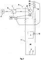
- Fig. 1 presents as a block diagram an elevator system according to a first embodiment of the invention, wherein the elevator car 1 is moved in the elevator hoistway 24 with an electric drive 6, which comprises the hoisting machine 16 of the elevator and also a frequency converter 7.
- the elevator car 1 and the counterweight 18 are suspended in the elevator hoistway 24 with hoisting ropes, a belt or corresponding (not shown in the figure) passing via the traction sheave of the hoisting machine 16 of the elevator.
- the power supply to the electric motor of the hoisting machine 16 of the elevator occurs with a frequency converter 7 from an electricity network 17.
- the control unit 10 of the elevator calculates the target value for speed, i.e.
- the frequency converter 7 adjusts the speed of the hoisting machine 16, and thereby indirectly also the speed of the elevator car 1, towards the aforementioned speed reference communicated to the frequency converter 7.
- the frequency converter measures the speed of rotation of the hoisting machine 16 of the elevator with a speed sensor, such as with a pulse encoder 20, a tachometer or corresponding, fitted to the shaft of the hoisting machine 16.
- the elevator system also comprises a monitoring arrangement, which is usually made to be at least partly separate from the rest of the control system of the elevator.
- the task of the monitoring arrangement is to take care of the safety of the elevator system.
- the monitoring arrangement comprises, in addition to the safety circuit 11 of the elevator, inter alia, monitoring units 8, 14, sensors 20, and braking devices 9, 12.
- the braking devices such as a machinery brake 9 and a safety gear 12, are connected to the safety circuit such that the machinery brake 9 and the safety gear 12 can be activated via the safety circuit.
- the monitoring arrangement measures the operating state of the elevator system and when it detects a hazardous situation performs one or more procedures for bringing the elevator system to a safe state. These procedures are e.g. activation of emergency braking and also prevention of the starting of a run of the elevator car 1.
- the sensors incorporated in the safety circuit 11 of the elevator system are e.g. the safety switches (not shown in the figure) monitoring the locking/state of entrances to the elevator hoistway 13, and also the limit switches (not shown in the figure) monitoring the limits of the areas of permitted movement of the elevator car 1 in the elevator hoistway 24.
- the speed of the elevator car is measured with sensors 20 that measure the speed of rotation of the hoisting machine 16.
- the monitoring arrangement comprises speed monitoring units 14, which are disposed in the bottom end zone of the elevator hoistway 24.
- Each of the speed monitoring units 14 comprises an input for the speed measurement signal 21 of the elevator car, which signal is formed here with the encoder 20 of the hoisting machine of the elevator; the speed measurement signal 21 of the elevator car could, however, also be formed with e.g. a sensor that measures the speed of rotation of a rope pulley 13 fitted in connection with the rope pulley 13 of the overspeed governor.
- the speed monitoring units 14 are disposed at different points beside the path of movement of the elevator car 1.
- the speed monitoring units 14 are connected to the safety circuit 11 of the elevator such that each of the speed monitoring units is able, if necessary, to activate the machinery brake 9.
- the monitoring arrangement measures the speed of the elevator car 1 and compares the measured speed to the limit values for permitted speed. When the speed of the elevator car 1 exceeds the limit value for permitted speed, the monitoring arrangement activates consecutive emergency braking procedures such that the deceleration of the elevator car increases progressively.
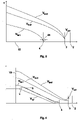
- Fig. 3 illustrates in more detail some limit values v lim1 , v lim2 for permitted speed according to the embodiment of Fig. 1 , described in relation to the position 15 of the elevator car in the end zone of the elevator hoistway.
- Each of the limit values v lim1 , v lim2 for permitted speed of the elevator car depends upon the position 15 of the elevator car on its path of movement such that the limit value v lim1 , v lim2 for permitted speed, to which the speed v of the elevator car 1 is compared, decreases when the position 15 of the elevator car 1 towards the end 2 of the elevator hoistway changes.
- the control unit 8 of an emergency stop fitted in connection with the frequency converter 7 compares the speed v of the elevator car 1 measured with the encoder 20 of the hoisting machine of the elevator to the first limit value v lim1 for permitted speed.
- the control unit 8 of an emergency stop activates a first emergency braking procedure.
- a first emergency braking procedure the control unit 8 of an emergency stop controls the electric drive 6, adjusting the speed v of the elevator car towards the target value 5 for speed during an emergency stop.
- the control unit 8 of an emergency stop also calculates the aforementioned target value 5 for speed during an emergency stop such that the target value for speed during an emergency stop is formed independently from the speed reference during normal operation of the elevator calculated by the control unit 10 of the elevator.
- the aforementioned first limit value v liml for permitted speed of an elevator car is determined such that the elevator car can be stopped at a first deceleration a 1 at the terminal floor 4, or in the immediate proximity of the terminal floor 4, from the speed v that the elevator car has at the moment of activating the first emergency braking procedure.
- the first limit value v liml for permitted speed in the equation above is increased by adding the term ⁇ s to the distance of the elevator car from the terminal floor s. This ensures that the first emergency braking procedure is not activated in the proximity of the stopping floor of the elevator owing to a fluctuation in the instantaneous speed of the elevator car.
- the speed monitoring units 14 presented above that are fitted beside the path of movement of the elevator car 1 monitor the speed v of the elevator car 1 arriving at the point of a speed monitoring unit 14.
- the speed monitoring unit 14 compares the speed data of the speed measurement signal 21 of the elevator car to the second limit value v lim2 for permitted speed of the elevator car, which limit value is determined for each speed monitoring unit 14 separately such that the limit values for permitted speed of the different monitoring units 14 are located on the limit value curve for permitted speed of the second limit value v lim2 , which curve is illustrated in Fig. 3 .
- the speed monitoring unit 14 activates, as a second emergency braking procedure, the machinery brake 9.
- the aforementioned second limit value v lim2 for permitted speed of the elevator car is determined such that the speed of the elevator car can be slowed down before collision with the end buffer 3 at a second deceleration a 2 , greater than the first deceleration a1, determined by the machinery brake 9 to the permitted buffer collision speed v coll from the speed v that the elevator car has at the moment of activating the second emergency braking procedure.
- the second limit value V lim2 for speed in the equation above is reduced for safety reasons with the term ⁇ v safety . This ensures an adequate braking distance irrespective of a possible instantaneous fluctuation in the deceleration of the elevator car and also irrespective of e.g. an activation delay of the machinery brake.
- the accuracy of the monitoring of the movement of the elevator car can be improved by increasing the number of consecutively disposed speed monitoring units 14 such that the intermediate distance between the speed monitoring units 14 decreases.
- Fig. 2 presents as a block diagram an elevator system according to a second embodiment of the invention, wherein the elevator car 1 is moved in the elevator hoistway 13 with an electric drive 6, which comprises the hoisting machine 16 of the elevator and also a frequency converter 7.
- the elevator car 1 and the counterweight 18 are suspended in the elevator hoistway 24 with hoisting ropes, a belt or corresponding (not shown in the figure) passing via the traction sheave of the hoisting machine 16 of the elevator.
- the power supply to the electric motor of the hoisting machine 16 of the elevator occurs with a frequency converter 7 from an electricity network 17.
- the control unit 10 of the elevator calculates the target value for speed, i.e.
- the frequency converter 7 adjusts the speed of the hoisting machine 16, and thereby indirectly also the speed of the elevator car 1, towards the aforementioned speed reference communicated to the frequency converter 7.
- the frequency converter measures the speed of rotation of the hoisting machine 16 of the elevator with a speed sensor, such as with a pulse encoder 20, a tachometer or corresponding, fitted to the shaft of the hoisting machine 16.
- the elevator system also comprises a monitoring arrangement, which is usually made to be at least partly separate from the rest of the control system of the elevator.
- the task of the monitoring arrangement is to take care of the safety of the elevator system.
- the monitoring arrangement comprises, in addition to the safety circuit 11 of the elevator, inter alia, monitoring units 8, sensors 20, 22, and braking devices 9, 12.
- the braking devices such as a machinery brake 9 and a safety gear 12, are connected to the safety circuit such that the machinery brake 9 and the safety gear 12 can be activated via the safety circuit.
- the monitoring arrangement measures the operating state of the elevator system and when it detects a hazardous situation performs one or more procedures for bringing the elevator system to a safe state. Such procedures are, inter alia, activation of emergency braking and also prevention of the starting of a run of the elevator car 1.
- the sensors incorporated in the safety circuit 11 of the elevator system are e.g. the safety switches (not shown in the figure) monitoring the locking/state of entrances to the elevator hoistway 13, and also the limit switches (not shown in the figure) monitoring the limits of the areas of permitted movement of the elevator car 1 in the elevator hoistway 24.
- the speed of the elevator car is measured with sensors 20 that measure the speed of rotation of the hoisting machine 16. Additionally, in this embodiment of the invention the speed of the elevator car is measured directly with a sensor 22, which is arranged in connection with the rope pulley 13 of the overspeed governor, for measuring the speed of rotation of the rope pulley 13.
- the monitoring arrangement also comprises a speed monitoring unit 23, which is connected to a sensor 22 arranged in connection with the rope pulley 13.
- the speed monitoring unit 23 is connected to the safety circuit of the elevator.
- the monitoring arrangement measures the speed of the elevator car 1 and compares the measured speed to the limit values for permitted maximum speed. When the speed of the elevator car 1 exceeds the limit value for permitted speed, the monitoring arrangement activates consecutive emergency braking procedures such that the deceleration of the elevator car increases progressively.
- Fig. 3 illustrates in more detail some limit values v lim1 , v lim2 , v lim3 for permitted speed according to the embodiment of Fig. 2 , described in relation to the position 15 of the elevator car.
- Each of the limit values v lim1 , v lim2 , v lim3 for permitted speed of the elevator car depends upon the position 15 of the elevator car on its path of movement such that the limit value v lim1 , v lim2 for permitted speed, to which the speed v of the elevator car 1 is compared, decreases when the position 15 of the elevator car 1 towards the end 2 of the elevator hoistway changes.
- the control unit 8 of an emergency stop fitted in connection with the frequency converter 7 compares the speed v of the elevator car 1 measured with the encoder 20 of the hoisting machine of the elevator to the first limit value v liml for permitted speed.
- the control unit 8 of an emergency stop activates a first emergency braking procedure.
- a first emergency stop procedure the control unit 8 of an emergency stop controls the electric drive 6, adjusting the speed v of the elevator car towards the target value 5 for speed during an emergency stop.
- the control unit 8 of an emergency stop also calculates the aforementioned target value 5 for speed during an emergency stop such that the target value 5 for speed during an emergency stop is formed independently from the speed reference during normal operation of the elevator calculated by the control unit 10 of the elevator.
- the aforementioned first limit value v liml for permitted speed of an elevator car is determined such that the elevator car can be stopped at a first deceleration a 1 at the terminal floor 4, or in the immediate proximity of the terminal floor 4, from the speed v that the elevator car has at the moment of activating the first emergency stop procedure.
- the first limit value v liml for permitted speed in the equation above is increased by adding the term ⁇ s to the distance of the elevator car from the terminal floor s. This ensures that the first emergency braking procedure is not activated in the proximity of the stopping floor of the elevator owing to a fluctuation in the instantaneous speed of the elevator car.
- the sensor 22 presented above that is arranged in connection with the rope pulley 13 of the overspeed governor measures the speed v of the elevator car 1.
- the speed monitoring unit 23 connected in connection with the sensor 22 compares the speed data measured by the sensor 22 also to the second limit value v lim2 for permitted speed of the elevator car. If the speed v of the elevator car 1 still increases, exceeding the second limit value v lim2 for permitted speed that is larger than the aforementioned first limit value v lim1 for permitted speed, the speed monitoring unit 23 activates, as a second emergency braking procedure, the machinery brake 9.
- the speed monitoring unit 23 connected in connection with the sensor 22 determines the aforementioned second limit value v lim2 for permitted speed of the elevator car such that the speed of the elevator car can be slowed down before collision with the end buffer 3 at a second deceleration a 2 , greater than the first deceleration a1, determined by the machinery brake 9 to the permitted buffer collision speed V coll from the speed v that the elevator car has at the moment of activating the second emergency braking procedure.
- the second limit value v lim2 for speed in the equation above is reduced for safety reasons with the term ⁇ v safety . This ensures an adequate braking distance irrespective of a possible instantaneous fluctuation in the deceleration of the elevator car and also irrespective of e.g. an activation delay of the machinery brake.
- the speed monitoring unit 23 connected in connection with the sensor 22 compares the speed data measured by the sensor 22 also to the third limit value v lim3 for permitted speed of the elevator car. If the speed v of the elevator car 1 still increases, exceeding the third limit value v lim3 for permitted speed that is larger than the aforementioned second limit value v lim2 for permitted speed, the speed monitoring unit 23 activates, as a third emergency braking procedure, the safety gear 12 of the elevator car by stopping the rotation of the rope pulley 13 of the overspeed governor, and thus the movement of the rope of the overspeed governor, by controlling a solenoid into the path of movement of the rope pulley 13 of the overspeed governor.
- the speed monitoring unit 23 connected in connection with the sensor 22 determines the aforementioned third limit value v lim3 for permitted speed of the elevator car such that the speed of the elevator car 1 can be slowed down before collision with the end buffer 3 at a third deceleration a3 determined by the safety gear 12 of the elevator car to the permitted buffer collision speed v coll from the speed v that the elevator car has at the moment of activating the third emergency braking procedure.
- the third limit value v lim3 for speed in the equation above is further reduced for safety reasons with the term ⁇ v safety . This ensures an adequate braking distance irrespective of a possible instantaneous fluctuation in the deceleration of the elevator car and also irrespective of e.g. an activation delay of the safety gear of the elevator car.
- the magnitude of the progressive increase in deceleration in connection with the first and the second emergency braking procedure is in the first and second embodiment of the invention set at ten percent of the normal deceleration of the elevator, in which case e.g. when the normal deceleration determined by the speed reference of the elevator is 1m/s ⁇ 2 the first deceleration according to the first emergency braking procedure is approx. 1.1m/s ⁇ 2 and the second deceleration according to the second emergency braking procedure is approx. 1.2m/s ⁇ 2.
- Fig. 4 further presents the speed reference v ref of an elevator, the starting moment 19 of the deceleration phase of an elevator car, the target value 5 for speed during an emergency stop, the limit values v lim1 ,v lim2, v lim3 for permitted speed of an elevator car, and also the measured speed v of an elevator car as a function of time in the deceleration phase of a run of an elevator car.
- the monitoring of the movement of an elevator car in the bottom part of an elevator hoistway is described.
- the invention can, however, be used for monitoring the movement of an elevator car also in the top part of an elevator hoistway in a corresponding manner, taking into account the effect on the second and third deceleration of the elevator car possibly caused by a change in the direction of movement of the masses of the elevator.
- the invention can be applied to monitoring the movement of a counterweight, instead of or in addition to the movement of an elevator car.
- the elevator system according to the invention can be provided with a counterweight or can be one without a counterweight.
Landscapes
- Engineering & Computer Science (AREA)
- Automation & Control Theory (AREA)
- Computer Networks & Wireless Communication (AREA)
- Mechanical Engineering (AREA)
- Maintenance And Inspection Apparatuses For Elevators (AREA)
- Elevator Control (AREA)
Description
- The invention relates to the safety of elevators and more particularly to the monitoring of the movement of an elevator car.
- The electric drive of an elevator attends to the moving of an elevator car in an elevator hoistway between stopping floors. The control system of the elevator forms a target value for the speed of the elevator car, i.e. a speed reference, for the electric drive. The speed reference can be divided into the acceleration phase of a run, the phase of even speed, and also the deceleration phase. The control system of the elevator starts the deceleration phase of a run when the elevator car has arrived at a predefined distance from the stopping floor. Normally the speed of the elevator car decelerates in a controlled manner at the deceleration determined by the speed reference such that the speed of the elevator car decreases to zero when the elevator car arrives at the stopping floor. The aim, especially when the elevator car stops at the terminal floor, is to ensure that the speed of the elevator car decelerates rapidly enough, because otherwise the elevator car or the counterweight is in danger of colliding with the end buffer. It is particularly important to ensure adequate deceleration when using so-called shallow end zones, such as a shallow pit of the elevator hoistway or shallow top clearance in the top part of the elevator hoistway. When using shallow end zones also the length of the end buffers, and therefore the collision damping capability, is usually limited. To ensure deceleration of the elevator car, the speed of an elevator car approaching the terminal floor is measured, and if the speed exceeds a set monitoring limit a mechanical stopping appliance, such as a safety gear, is activated to stop the elevator car. The aforementioned monitoring limit can be determined dependently on location such that the same value for the monitoring limit is always used in the same location and at the same distance from the end of the elevator hoistway.
- A passenger in the elevator may find the gripping situation a quite unpleasant experience owing to the significantly greater than normal deceleration of the elevator car during the gripping. When the elevator is driving upwards, if the deceleration of the elevator car were to exceed the acceleration of free fall of the attractive force of the earth's gravity when the elevator is driving upwards, there would be the additional danger that an elevator passenger would rise into the air as a consequence of the gripping situation. Additionally, during an emergency stop of the elevator car the deceleration might vary in different parts of the elevator hoistway owing to, among other things, the effect of the weight of the elevator ropes. Elongation of the elevator ropes, on the other hand, might result in the speed of the elevator car during deceleration being momentarily greater than that permitted even if the speed of the traction sheave of the hoisting machine were to decelerate in the manner specified by the speed reference. Particularly with large travel heights, speed monitoring could activate the safety gear as a result of instantaneous overspeed caused by elongation of the elevator ropes.
-
EP 1 997 766 A1 -
EP 1953107 A1 , on which the preambles ofclaims -
US 7533763 B2 discloses a safety system comprising an electric safety device, which monitors the velocity and position of the elevator in the elevator shaft. The safety device is e.g. a computer that is able to stop the elevator, using the brake of the hoisting machine or an optional car brake. The safety system forms a continuous limit curve for control of elevator speed. The limit curve defines the limits of allowed elevator motion, which are determined on the basis of the nominal speed of the elevator and the location of the car. The safety system of the invention comprises measuring means for continuous measurement of elevator motion data and a safety device that receives data about the motion of the elevator, calculates its velocity at each instant of time utilizing the elevator motion data and watches the elevator motion to ensure that it remains within the allowed limit curve. Moreover, the safety system comprises a stopping device for stopping uncontrolled motion of the car if the elevator motion exceeds the limit curve set for it. -
US 2009/2777724 A1 discloses an elevator system comprising a decentralized control system having a first analysis unit associated with one of the at least one elevator cabin, a second analysis unit associated with the elevator shaft, and a number of third analysis units. The first, second, and third analysis units are connected to one another via a bus connection, wherein signal transmission occurs via the bus connection using a safety protocol such that the transmission of safety-relevant data is allowed between the analysis units. The safety protocol is structured such that transmission errors are detected and data corruption is indicated. Moreover, the first analysis unit associated with the elevator cabin is connected to sensors for securely detecting the position of the elevator cabin, allowing control of safety devices of the elevator system. The second analysis unit is connected to a drive of the elevator system. - The aim of the invention is therefore to disclose a method for monitoring the movement of an elevator car, and also an elevator system wherein the movement of an elevator car is monitored. According to the invention, the deceleration of the elevator car is increased progressively in connection with an emergency stop of the elevator car by activating separate emergency braking procedures consecutively such that it is endeavored to stop the elevator car with as small a deceleration as possible while, however, simultaneously taking into account the safety of the elevator passengers.
- In relation to the characteristic attributes of the invention, reference is made to the claims. Some inventive embodiments and inventive combinations of the various embodiments are also presented in the descriptive section and in the drawings of the present application.
- The invention relates to a method for emergency braking of an elevator car. In the method a first emergency braking procedure is activated for braking the elevator car at a first deceleration a1 if the speed of the elevator car exceeds the first limit value vlim1 for permitted speed, and in the method a second emergency braking procedure is further activated for braking the elevator car at a second deceleration a2 that is greater than the first, if the speed of the elevator car exceeds the second limit value vlim2 for permitted speed that is greater than the first limit value vliml for permitted speed. The aforementioned first deceleration a1 of the elevator car is preferably greater than the normal deceleration of the elevator car according to the deceleration phase of the speed reference vref. According to the basic idea of the invention the deceleration of the elevator car is increased progressively by activating consecutive emergency braking procedures during an emergency stop such that the deceleration of the elevator car achieved by the subsequent emergency braking procedure is always greater than the deceleration of the elevator car achieved by the preceding emergency braking procedure.
- In one embodiment of the invention a third emergency braking procedure is further activated for braking the elevator car at a third deceleration a3 that is greater than the second, if the speed of the elevator car exceeds the third limit value vlim3 for permitted speed that is greater than the second limit value vlim2 for permitted speed.
- In a preferred embodiment of the invention, as a first emergency braking procedure, the speed of the elevator car is adjusted towards the target value for speed during an emergency stop by controlling the electric drive of the elevator with a control unit of an emergency stop and, as a second emergency braking procedure, one or more machinery brakes of the hoisting machine of the elevator are activated. The aforementioned target value for speed during an emergency stop is determined such that the target value for speed decreases by the angular coefficient determined by the first deceleration a1 according to the aforementioned first emergency stop procedure of the elevator car. The aforementioned one or more machinery brakes of the hoisting machine of the elevator is/are dimensioned, on the other hand, to exert braking force on the traction sheave of the hoisting machine of the elevator, the second deceleration a2 achieved by which braking force is greater than the first deceleration a1 according to the first emergency stop procedure. In some embodiments of the invention one or more machinery brakes of the hoisting machine are activated consecutively to each other such that first only one machinery brake is activated; after this, if the speed of the elevator car exceeds the set limit value for permitted speed, a second machinery brake is further activated.
- In a preferred embodiment of the invention, as a third emergency braking procedure, the safety gear of the elevator car is activated. The safety gear is in this case dimensioned to exert braking force between the elevator car and the guide rail, the third deceleration a3 achieved by which braking force is greater than the second deceleration a2 according to the second emergency stop procedure.
- With regard to the second aspect, the invention relates to an elevator system, which comprises an electric drive, for moving an elevator car in an elevator hoistway; a machinery brake; a monitoring arrangement, which monitoring arrangement comprises means for controlling the electric drive and the machinery brake; and which monitoring arrangement is arranged to activate a first emergency braking procedure for braking the elevator car at a first deceleration a1 if the speed of the elevator car exceeds the first limit value vlim1 for permitted speed; and which monitoring arrangement is arranged to further activate a second emergency braking procedure for braking the elevator car at a second deceleration a2 that is greater than the first, if the speed of the elevator car exceeds the second limit value vlim2 for permitted speed that is greater than the first limit value vlim1 for permitted speed. The aforementioned first deceleration a1 is preferably greater than the normal deceleration of the elevator car according to the deceleration phase of the speed reference vref. According to the basic idea of the invention the deceleration of the elevator car is increased progressively by activating consecutive emergency braking procedures during an emergency stop such that the deceleration of the elevator car achieved by the subsequent emergency braking procedure is always greater than the deceleration of the elevator car achieved by the preceding emergency braking procedure. The aforementioned consecutive different emergency braking procedures are preferably independent of each other such that braking apparatuses separate to each other are used in the different emergency braking procedures. The progressive increase in deceleration in connection with the first and the second emergency braking procedure can be e.g. approx. ten percent of the normal deceleration of the elevator.
- The monitoring arrangement according to the invention preferably comprises a control unit of an emergency stop. In a preferred embodiment of the invention the control unit of an emergency stop is, as a first emergency braking procedure, arranged to adjust the speed of the elevator car with the electric drive towards the target value for speed during an emergency stop. The control unit of an emergency stop is preferably fitted into the control system of the elevator such that the calculation performed by the control unit of an emergency stop, said calculation being of the target value for the speed of the elevator car during an emergency stop, is independent of any other calculation of the speed reference of the elevator. The aforementioned target value for speed during an emergency stop is determined such that the target value for speed decreases by the angular coefficient determined by the first deceleration a1 according to the aforementioned first emergency stop procedure of the elevator car.
- According to the invention the monitoring arrangement is, as a second emergency braking procedure, arranged to activate one or more machinery brakes for braking the elevator car at a second deceleration a2 that is greater than the first. The aforementioned one or more machinery brakes is/are dimensioned to exert braking force on the traction sheave of the hoisting machine of the elevator, the second deceleration a2 achieved by which braking force is greater than the first deceleration a1 according to the first emergency stop procedure.
- In a preferred embodiment of the invention the elevator system comprises a safety gear; and the monitoring arrangement comprises means for controlling the safety gear; and the monitoring arrangement is in this case arranged to further activate the safety gear, as a third emergency braking procedure, for braking the elevator car at a third deceleration a3 that is greater than the second, if the speed of the elevator car exceeds the third limit value Vlim3 for permitted speed that is greater than the second limit value vlim2 for permitted speed. The safety gear is in this case dimensioned to exert braking force between the elevator car and the guide rail, the third deceleration a3 achieved by which braking force is greater than the second deceleration a2 according to the second emergency stop procedure.
- Each of the aforementioned limit values vlim1, Vlim2, Vlim3 for permitted speed of the elevator car depends preferably upon the position of the elevator car on its path of movement such that the limit value Vlim1, Vlim2, Vlim3 for permitted speed, to which the speed of the elevator car is compared, decreases when the position of the elevator car towards the end of the elevator hoistway changes.
- In a preferred embodiment of the invention the first limit value Vlim1 for permitted speed of the elevator car in this case decreases towards the end of the elevator hoistway by a gradient, which gradient depends on the aforementioned first deceleration a1 of the elevator car. The second limit value vlim2 for permitted speed of the elevator car, on the other hand, decreases in this case by a gradient, which gradient depends on the aforementioned second deceleration a2 of the elevator car. The first limit value Vlim1 for permitted speed of the elevator car is in this case determined preferably by means of the first deceleration a1 of the elevator car and also the distance of the elevator car from the terminal floor s, using the equation:

- The second limit value vlim2 for permitted speed of the elevator car is in this case determined preferably by means of the second deceleration a2 of the elevator car, the distance of the elevator car from the end buffer d and also the permitted buffer collision speed vcoll, using the equation:

- The third limit value Vlim3 for permitted speed of the elevator car, on the other hand, in this case preferably decreases by a gradient, which gradient depends on the aforementioned third deceleration a3 of the elevator car. The third limit value Vlim3 for permitted speed of the elevator car is in this case determined preferably by means of the third deceleration a3 of the elevator car, the distance of the elevator car/counterweight from the end buffer d and also the permitted buffer collision speed vcoll, using the equation:

- It must be noted here that above the constant values are used for the first a1, the second a2 and the third a3 deceleration of the elevator car. In practice, however, the deceleration might vary slightly during the braking, e.g. owing to variation in the structure of the braking apparatus, in the braking method and/or in the friction. In this case the first a1, the second a2 and the third a3 deceleration are understood to be the average deceleration during braking. The first limit value vlim1 for permitted speed of the elevator car presented above approaches the speed reference of the elevator car during the deceleration phase of the speed reference. For this reason, when the elevator car approaches a stopping floor an instantaneous fluctuation in the speed of the elevator car could cause unnecessary activation of the first emergency braking procedure. In order to prevent this the first limit value for speed is increased, according to the invention, in the proximity of the stopping floor, e.g. by adding a defined additional term to the first limit value for speed and/or by increasing the value of the distance of the elevator car from the terminal floor s in the calculation equation of the first limit value for speed presented above such that the stopping point of the elevator is located slightly beyond the terminal floor. The equations of the second and third limit values Vlim2, Vlim3 for permitted speed presented above describe the maximum value for which the limit values can be set. Before commissioning, however, the second and third limit values Vlim2, Vlim3 for permitted speed can for safety reasons be reduced slightly, which ensures an adequate braking distance irrespective of a possible fluctuation in the deceleration of the elevator car and also irrespective of e.g. activation delays, such as an activation delay of the machinery brake and/or of the safety gear, of the emergency braking procedures.
- The aforementioned first vlim1, second vlim2 and third Vlim3 limit value for permitted speed preferably do not overlap each other but instead they are determined such that the aforementioned third limit value vlim3 for permitted speed is always greater in absolute value than the aforementioned second limit value vlim2 for permitted speed, and the aforementioned second limit value vlim2 for permitted speed is always greater in absolute value than the aforementioned first limit value vlim1 for permitted speed.
- In one embodiment of the invention the monitoring arrangement comprises speed monitoring units, which speed monitoring units are disposed in the end zone of the elevator hoistway. Each speed monitoring unit comprises an input for the speed measurement signal of the elevator car. The speed monitoring units are disposed at different points beside the path of movement of the elevator car. The speed monitoring units are connected to the safety circuit of the elevator such that each speed monitoring unit is able, if necessary, to activate the machinery brake. In some embodiments the speed measurement of each speed monitoring unit is duplicated such that each speed monitoring unit comprises an input for the machine encoder that measures the movement of the traction sheave of the hoisting machine and also in addition an input for the encoder that measures the movement of the elevator car and that is to be connected to a guide rail via a rotating roller fitted in connection with the elevator car. In this case the speed monitoring unit is arranged to compare the measuring signals of the different sensors to each other and when it detects that the measuring data deviate from each other by more than what is permitted the speed monitoring unit is arranged to activate an emergency braking procedure.
- In a second embodiment of the invention the monitoring arrangement comprises a sensor, which sensor is arranged in connection with the rope pulley of the overspeed governor, for measuring the speed of rotation of the rope pulley. In some embodiments the monitoring arrangement comprises two sensors, both of which are arranged in connection with the rope pulley of the overspeed governor for duplicating the speed measurement. The monitoring arrangement also comprises a speed monitoring unit, which is connected to the aforementioned sensor/sensors. In those embodiments in which the monitoring arrangement comprises two sensors, the speed monitoring unit is arranged to compare the measuring signals of the different sensors to each other and when it detects that the measuring data deviate from each other by more than what is permitted the speed monitoring unit is arranged to activate an emergency braking procedure. The speed monitoring unit is connected to the safety circuit of the elevator, for activating the machinery brake and/or the safety gear. The speed monitoring unit is arranged to activate a second emergency braking procedure for braking the elevator car at a second deceleration if the speed of the elevator car exceeds the second limit value for permitted speed. The speed monitoring unit is arranged to further activate a third emergency braking procedure for braking the elevator car at a third deceleration that is greater than the second, if the speed of the elevator car exceeds the third limit value for permitted speed that is greater than the second limit value for permitted speed.
- When determining the aforementioned limit values Vlim1, Vlim2, Vlim3 for permitted speed by means of the acceleration a1, a2, a3 according to each emergency braking procedure in the manner presented above, the emergency braking procedures to be activated consecutively can always be started at the correct moment and in a controlled manner such that the emergency braking procedure to be activated at any given time is able to stop the elevator car safely before the end of the elevator hoistway if the emergency braking apparatus to be used in the emergency braking procedure is operationally viable. The safety of an elevator system also increases as the number of consecutive emergency braking procedures increases. The set limit values Vlim1, Vlim2, Vlim3 for permitted speed correspond essentially to the maximum possible limit values for safe operation. Since the instantaneous speed of the elevator car can vary within the scope of the aforementioned limit values vlim1, vlim2, vlim3 for permitted speed, according to the invention it is thus possible with the set limit values vlim1, vlim2, vlim3 for permitted speed to essentially reduce e.g. emergency stops occurring as a consequence of an instantaneous speed fluctuation/overspeed of the elevator car caused by elongation of the elevator ropes.
- In the invention the speed of the elevator car can also be determined e.g. from the measuring signal of an acceleration sensor that is fitted in connection with the elevator car and that moves along with the elevator car. The determination of speed from the measuring signal of the acceleration sensor that moves along with the elevator car is thus advantageous so that in this case no measuring error occurs in the speed data of the elevator car e.g. when the ropes slip on the traction sheave of the hoisting machine of the elevator.
- The aforementioned summary, as well as the additional features and advantages of the invention presented below, will be better understood by the aid of the following description of some embodiments, said description not limiting the scope of application of the invention.
-
- Fig. 1
- presents as a block diagram an elevator system according to a first embodiment of the invention
- Fig. 2
- presents as a block diagram an elevator system according to a second embodiment of the invention
- Fig. 3
- illustrates some limit values for permitted speed according to the invention, described in relation to the position of the elevator car
- Fig. 4
- illustrates the speed reference of an elevator, the limit values for permitted speed of an elevator car, and also the measured speed of an elevator car during the deceleration phase of a run of the elevator car
-
Fig. 1 presents as a block diagram an elevator system according to a first embodiment of the invention, wherein theelevator car 1 is moved in theelevator hoistway 24 with anelectric drive 6, which comprises the hoistingmachine 16 of the elevator and also afrequency converter 7. Theelevator car 1 and the counterweight 18 are suspended in theelevator hoistway 24 with hoisting ropes, a belt or corresponding (not shown in the figure) passing via the traction sheave of the hoistingmachine 16 of the elevator. The power supply to the electric motor of the hoistingmachine 16 of the elevator occurs with afrequency converter 7 from anelectricity network 17. Thecontrol unit 10 of the elevator calculates the target value for speed, i.e. the speed reference, of theelevator car 1 to be moved in theelevator hoistway 24 and thefrequency converter 7 adjusts the speed of the hoistingmachine 16, and thereby indirectly also the speed of theelevator car 1, towards the aforementioned speed reference communicated to thefrequency converter 7. For adjusting the speed the frequency converter measures the speed of rotation of the hoistingmachine 16 of the elevator with a speed sensor, such as with apulse encoder 20, a tachometer or corresponding, fitted to the shaft of the hoistingmachine 16. - The elevator system also comprises a monitoring arrangement, which is usually made to be at least partly separate from the rest of the control system of the elevator. The task of the monitoring arrangement is to take care of the safety of the elevator system. The monitoring arrangement comprises, in addition to the
safety circuit 11 of the elevator, inter alia,monitoring units sensors 20, andbraking devices machinery brake 9 and asafety gear 12, are connected to the safety circuit such that themachinery brake 9 and thesafety gear 12 can be activated via the safety circuit. The monitoring arrangement measures the operating state of the elevator system and when it detects a hazardous situation performs one or more procedures for bringing the elevator system to a safe state. These procedures are e.g. activation of emergency braking and also prevention of the starting of a run of theelevator car 1. - The sensors incorporated in the
safety circuit 11 of the elevator system are e.g. the safety switches (not shown in the figure) monitoring the locking/state of entrances to theelevator hoistway 13, and also the limit switches (not shown in the figure) monitoring the limits of the areas of permitted movement of theelevator car 1 in theelevator hoistway 24. The speed of the elevator car is measured withsensors 20 that measure the speed of rotation of the hoistingmachine 16. - In this embodiment of the invention the monitoring arrangement comprises
speed monitoring units 14, which are disposed in the bottom end zone of theelevator hoistway 24. Each of thespeed monitoring units 14 comprises an input for thespeed measurement signal 21 of the elevator car, which signal is formed here with theencoder 20 of the hoisting machine of the elevator; thespeed measurement signal 21 of the elevator car could, however, also be formed with e.g. a sensor that measures the speed of rotation of arope pulley 13 fitted in connection with therope pulley 13 of the overspeed governor. Thespeed monitoring units 14 are disposed at different points beside the path of movement of theelevator car 1. Thespeed monitoring units 14 are connected to thesafety circuit 11 of the elevator such that each of the speed monitoring units is able, if necessary, to activate themachinery brake 9. - The monitoring arrangement measures the speed of the
elevator car 1 and compares the measured speed to the limit values for permitted speed. When the speed of theelevator car 1 exceeds the limit value for permitted speed, the monitoring arrangement activates consecutive emergency braking procedures such that the deceleration of the elevator car increases progressively.Fig. 3 illustrates in more detail some limit values vlim1, vlim2 for permitted speed according to the embodiment ofFig. 1 , described in relation to theposition 15 of the elevator car in the end zone of the elevator hoistway. Each of the limit values vlim1, vlim2 for permitted speed of the elevator car depends upon theposition 15 of the elevator car on its path of movement such that the limit value vlim1, vlim2 for permitted speed, to which the speed v of theelevator car 1 is compared, decreases when theposition 15 of theelevator car 1 towards theend 2 of the elevator hoistway changes. Thecontrol unit 8 of an emergency stop fitted in connection with thefrequency converter 7 compares the speed v of theelevator car 1 measured with theencoder 20 of the hoisting machine of the elevator to the first limit value vlim1 for permitted speed. If the speed v of theelevator car 1 exceeds the first limit value vliml for permitted speed, thecontrol unit 8 of an emergency stop activates a first emergency braking procedure. As a first emergency braking procedure thecontrol unit 8 of an emergency stop controls theelectric drive 6, adjusting the speed v of the elevator car towards thetarget value 5 for speed during an emergency stop. Thecontrol unit 8 of an emergency stop also calculates theaforementioned target value 5 for speed during an emergency stop such that the target value for speed during an emergency stop is formed independently from the speed reference during normal operation of the elevator calculated by thecontrol unit 10 of the elevator. - The aforementioned first limit value vliml for permitted speed of an elevator car is determined such that the elevator car can be stopped at a first deceleration a1 at the
terminal floor 4, or in the immediate proximity of theterminal floor 4, from the speed v that the elevator car has at the moment of activating the first emergency braking procedure. The first limit value vliml for permitted speed is determined by means of the first deceleration a1 of the elevator car and also the distance of the elevator car from the terminal floor s from the equation:
- In addition, the first limit value vliml for permitted speed in the equation above is increased by adding the term Δs to the distance of the elevator car from the terminal floor s. This ensures that the first emergency braking procedure is not activated in the proximity of the stopping floor of the elevator owing to a fluctuation in the instantaneous speed of the elevator car.
- The
speed monitoring units 14 presented above that are fitted beside the path of movement of theelevator car 1 monitor the speed v of theelevator car 1 arriving at the point of aspeed monitoring unit 14. Thespeed monitoring unit 14 compares the speed data of thespeed measurement signal 21 of the elevator car to the second limit value vlim2 for permitted speed of the elevator car, which limit value is determined for eachspeed monitoring unit 14 separately such that the limit values for permitted speed of thedifferent monitoring units 14 are located on the limit value curve for permitted speed of the second limit value vlim2, which curve is illustrated inFig. 3 . If the speed v of theelevator car 1 still increases, exceeding the second limit value vlim2 for permitted speed that is larger than the aforementioned first limit value vlim1 for permitted speed, thespeed monitoring unit 14 activates, as a second emergency braking procedure, themachinery brake 9. - The aforementioned second limit value vlim2 for permitted speed of the elevator car is determined such that the speed of the elevator car can be slowed down before collision with the
end buffer 3 at a second deceleration a2, greater than the first deceleration a1, determined by themachinery brake 9 to the permitted buffer collision speed vcoll from the speed v that the elevator car has at the moment of activating the second emergency braking procedure. The second limit value vlim2 for speed is determined by means of the second deceleration a2 of the elevator car, the distance of the elevator car from the end buffer d and also the permitted buffer collision speed vcoll, from the equation:
- In addition, the second limit value Vlim2 for speed in the equation above is reduced for safety reasons with the term Δvsafety. This ensures an adequate braking distance irrespective of a possible instantaneous fluctuation in the deceleration of the elevator car and also irrespective of e.g. an activation delay of the machinery brake.
- The accuracy of the monitoring of the movement of the elevator car can be improved by increasing the number of consecutively disposed
speed monitoring units 14 such that the intermediate distance between thespeed monitoring units 14 decreases. -
Fig. 2 presents as a block diagram an elevator system according to a second embodiment of the invention, wherein theelevator car 1 is moved in theelevator hoistway 13 with anelectric drive 6, which comprises the hoistingmachine 16 of the elevator and also afrequency converter 7. Theelevator car 1 and the counterweight 18 are suspended in theelevator hoistway 24 with hoisting ropes, a belt or corresponding (not shown in the figure) passing via the traction sheave of the hoistingmachine 16 of the elevator. The power supply to the electric motor of the hoistingmachine 16 of the elevator occurs with afrequency converter 7 from anelectricity network 17. Thecontrol unit 10 of the elevator calculates the target value for speed, i.e. the speed reference, of theelevator car 1 to be moved in theelevator hoistway 24 and thefrequency converter 7 adjusts the speed of the hoistingmachine 16, and thereby indirectly also the speed of theelevator car 1, towards the aforementioned speed reference communicated to thefrequency converter 7. For adjusting the speed the frequency converter measures the speed of rotation of the hoistingmachine 16 of the elevator with a speed sensor, such as with apulse encoder 20, a tachometer or corresponding, fitted to the shaft of the hoistingmachine 16. - The elevator system also comprises a monitoring arrangement, which is usually made to be at least partly separate from the rest of the control system of the elevator. The task of the monitoring arrangement is to take care of the safety of the elevator system. The monitoring arrangement comprises, in addition to the
safety circuit 11 of the elevator, inter alia,monitoring units 8,sensors braking devices machinery brake 9 and asafety gear 12, are connected to the safety circuit such that themachinery brake 9 and thesafety gear 12 can be activated via the safety circuit. The monitoring arrangement measures the operating state of the elevator system and when it detects a hazardous situation performs one or more procedures for bringing the elevator system to a safe state. Such procedures are, inter alia, activation of emergency braking and also prevention of the starting of a run of theelevator car 1. - The sensors incorporated in the
safety circuit 11 of the elevator system are e.g. the safety switches (not shown in the figure) monitoring the locking/state of entrances to theelevator hoistway 13, and also the limit switches (not shown in the figure) monitoring the limits of the areas of permitted movement of theelevator car 1 in theelevator hoistway 24. The speed of the elevator car is measured withsensors 20 that measure the speed of rotation of the hoistingmachine 16. Additionally, in this embodiment of the invention the speed of the elevator car is measured directly with asensor 22, which is arranged in connection with therope pulley 13 of the overspeed governor, for measuring the speed of rotation of therope pulley 13. - The monitoring arrangement also comprises a
speed monitoring unit 23, which is connected to asensor 22 arranged in connection with therope pulley 13. Thespeed monitoring unit 23 is connected to the safety circuit of the elevator. - The monitoring arrangement measures the speed of the
elevator car 1 and compares the measured speed to the limit values for permitted maximum speed. When the speed of theelevator car 1 exceeds the limit value for permitted speed, the monitoring arrangement activates consecutive emergency braking procedures such that the deceleration of the elevator car increases progressively.Fig. 3 illustrates in more detail some limit values vlim1, vlim2, vlim3 for permitted speed according to the embodiment ofFig. 2 , described in relation to theposition 15 of the elevator car. Each of the limit values vlim1, vlim2, vlim3 for permitted speed of the elevator car depends upon theposition 15 of the elevator car on its path of movement such that the limit value vlim1, vlim2 for permitted speed, to which the speed v of theelevator car 1 is compared, decreases when theposition 15 of theelevator car 1 towards theend 2 of the elevator hoistway changes. Thecontrol unit 8 of an emergency stop fitted in connection with thefrequency converter 7 compares the speed v of theelevator car 1 measured with theencoder 20 of the hoisting machine of the elevator to the first limit value vliml for permitted speed. If the speed v of theelevator car 1 exceeds the first limit value vliml for permitted speed, thecontrol unit 8 of an emergency stop activates a first emergency braking procedure. As a first emergency stop procedure thecontrol unit 8 of an emergency stop controls theelectric drive 6, adjusting the speed v of the elevator car towards thetarget value 5 for speed during an emergency stop. Thecontrol unit 8 of an emergency stop also calculates theaforementioned target value 5 for speed during an emergency stop such that thetarget value 5 for speed during an emergency stop is formed independently from the speed reference during normal operation of the elevator calculated by thecontrol unit 10 of the elevator. - The aforementioned first limit value vliml for permitted speed of an elevator car is determined such that the elevator car can be stopped at a first deceleration a1 at the
terminal floor 4, or in the immediate proximity of theterminal floor 4, from the speed v that the elevator car has at the moment of activating the first emergency stop procedure. The first limit value vlim1 for permitted speed is determined by means of the first deceleration a1 of the elevator car and also the distance of the elevator car from the terminal floor s from the equation:
- In addition, the first limit value vliml for permitted speed in the equation above is increased by adding the term Δs to the distance of the elevator car from the terminal floor s. This ensures that the first emergency braking procedure is not activated in the proximity of the stopping floor of the elevator owing to a fluctuation in the instantaneous speed of the elevator car.
- The
sensor 22 presented above that is arranged in connection with therope pulley 13 of the overspeed governor measures the speed v of theelevator car 1. Thespeed monitoring unit 23 connected in connection with thesensor 22 compares the speed data measured by thesensor 22 also to the second limit value vlim2 for permitted speed of the elevator car. If the speed v of theelevator car 1 still increases, exceeding the second limit value vlim2 for permitted speed that is larger than the aforementioned first limit value vlim1 for permitted speed, thespeed monitoring unit 23 activates, as a second emergency braking procedure, themachinery brake 9. - The
speed monitoring unit 23 connected in connection with thesensor 22 determines the aforementioned second limit value vlim2 for permitted speed of the elevator car such that the speed of the elevator car can be slowed down before collision with theend buffer 3 at a second deceleration a2, greater than the first deceleration a1, determined by themachinery brake 9 to the permitted buffer collision speed Vcoll from the speed v that the elevator car has at the moment of activating the second emergency braking procedure. The second limit value vlim2 for permitted speed is determined by means of the second deceleration a2 of the elevator car, the distance of the elevator car from the end buffer d and also the permitted buffer collision speed vcoll, from the equation: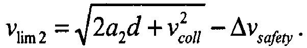
- In addition, the second limit value vlim2 for speed in the equation above is reduced for safety reasons with the term Δvsafety. This ensures an adequate braking distance irrespective of a possible instantaneous fluctuation in the deceleration of the elevator car and also irrespective of e.g. an activation delay of the machinery brake.
- The
speed monitoring unit 23 connected in connection with thesensor 22 compares the speed data measured by thesensor 22 also to the third limit value vlim3 for permitted speed of the elevator car. If the speed v of theelevator car 1 still increases, exceeding the third limit value vlim3 for permitted speed that is larger than the aforementioned second limit value vlim2 for permitted speed, thespeed monitoring unit 23 activates, as a third emergency braking procedure, thesafety gear 12 of the elevator car by stopping the rotation of therope pulley 13 of the overspeed governor, and thus the movement of the rope of the overspeed governor, by controlling a solenoid into the path of movement of therope pulley 13 of the overspeed governor. - The
speed monitoring unit 23 connected in connection with thesensor 22 determines the aforementioned third limit value vlim3 for permitted speed of the elevator car such that the speed of theelevator car 1 can be slowed down before collision with theend buffer 3 at a third deceleration a3 determined by thesafety gear 12 of the elevator car to the permitted buffer collision speed vcoll from the speed v that the elevator car has at the moment of activating the third emergency braking procedure. The third limit value vlim3 for permitted speed is determined by means of the third deceleration a3 of the elevator car, the distance of the elevator car from the end buffer d and also the permitted buffer collision speed vcoll, from the equation:
- In addition, the third limit value vlim3 for speed in the equation above is further reduced for safety reasons with the term Δvsafety. This ensures an adequate braking distance irrespective of a possible instantaneous fluctuation in the deceleration of the elevator car and also irrespective of e.g. an activation delay of the safety gear of the elevator car.
- The magnitude of the progressive increase in deceleration in connection with the first and the second emergency braking procedure is in the first and second embodiment of the invention set at ten percent of the normal deceleration of the elevator, in which case e.g. when the normal deceleration determined by the speed reference of the elevator is 1m/s^2 the first deceleration according to the first emergency braking procedure is approx. 1.1m/s^2 and the second deceleration according to the second emergency braking procedure is approx. 1.2m/s^2.
- For illustrative purposes and relating to the embodiments of the invention that are described above,
Fig. 4 further presents the speed reference vref of an elevator, the startingmoment 19 of the deceleration phase of an elevator car, thetarget value 5 for speed during an emergency stop, the limit values vlim1,vlim2, vlim3 for permitted speed of an elevator car, and also the measured speed v of an elevator car as a function of time in the deceleration phase of a run of an elevator car. - In the preceding embodiments of the invention, the monitoring of the movement of an elevator car in the bottom part of an elevator hoistway is described. The invention can, however, be used for monitoring the movement of an elevator car also in the top part of an elevator hoistway in a corresponding manner, taking into account the effect on the second and third deceleration of the elevator car possibly caused by a change in the direction of movement of the masses of the elevator. Likewise the invention can be applied to monitoring the movement of a counterweight, instead of or in addition to the movement of an elevator car.
- The elevator system according to the invention can be provided with a counterweight or can be one without a counterweight.
- The invention is described above by the aid of a few examples of its embodiment. It is obvious to the person skilled in the art that the invention is not limited only to the embodiments described above, but that many other applications are possible within the scope of the inventive concept defined by the claims.
Claims (19)
- Method for an emergency braking of an elevator car (1), in which method:a first emergency braking procedure is activated for braking the elevator car (1) at a first deceleration (a1) if the speed (v) of the elevator car exceeds a first limit value (vlim1) for permitted speed,characterized in thata second emergency braking procedure is further activated for braking the elevator car (1) at a second deceleration (a2) that is greater than the first deceleration (a1), if the speed (v) of the elevator car exceeds a second limit value (Vlim2) for permitted speed that is greater than the first limit value (vlim1) for permitted speed, wherein the first limit value (vlim1) for permitted speed is increased in the proximity of a terminal floor.
- Method according to claim 1, characterized in that the aforementioned first deceleration (a1) of the elevator car is greater than the normal deceleration of the elevator car according to the deceleration phase of the speed reference (vref).
- Method according to claim 1 or 2, characterized in that:- a third emergency braking procedure is further activated for braking the elevator car (1) at a third deceleration (a3) that is greater than the second deceleration (a2), if the speed (v) of the elevator car exceeds a third limit value (vlim3) for permitted speed that is greater than the second limit value (vlim2) for permitted speed.
- Method according to any of claims 1 - 3, characterized in that each of the aforementioned limit values (vlim1, vlim2, vlim3) for permitted speed of the elevator car depends upon the position (15) of the elevator car (1) on its path of movement such that the limit value (vlim1, vlim2, vlim3) for permitted speed, to which the speed (v) of the elevator car is compared, decreases when the position (15) of the elevator car (1) towards the end (2) of the elevator hoistway changes.
- Method according to claim 4, characterized in that the first limit value (vlim1) for permitted speed of the elevator car decreases by a gradient, which gradient depends on the aforementioned first deceleration (a1) of the elevator car.
- Method according to claim 4 or 5, characterized in that the second limit value (vlim2) for permitted speed of the elevator car decreases by a gradient, which gradient depends on the aforementioned second deceleration (a2) of the elevator car.
- Method according to any of claims 4 - 6, characterized in that the third limit value (vlim3) for permitted speed of the elevator car deceases by a gradient, which gradient depends on the aforementioned third deceleration (a3) of the elevator car.
- Method according to any of the preceding claims, characterized in that:- as the first emergency braking procedure the speed (v) of the elevator car is adjusted towards a target value (5) for speed during an emergency stop by controlling an electric drive (6) of the elevator with a control unit (8) of an emergency stop.
- Method according to any of the preceding claims, characterized in that:- as the second emergency braking procedure one or more machinery brakes (9) of a hoisting machine of the elevator is/are activated
- Method according to any of the preceding claims, characterized in that:
as the third emergency braking procedure a safety gear (12) of the elevator car is activated. - Elevator system, which comprises:an electric drive (6), for moving the elevator car (1) in the elevator hoistway (24);a machinery brake (9);a monitoring arrangement, which monitoring arrangement comprises means (8, 11) for controlling the electric drive (6) and the machinery brake (9);and which monitoring arrangement is arranged to activate a first emergency braking procedure for braking the elevator car (1) at a first deceleration (a1), if the speed (v) of the elevator car exceeds a first limit value (vlim1) for permitted speed;characterized in that the monitoring arrangement is arranged to further activate a second emergency braking procedure for braking the elevator car (1) at a second deceleration (a2) that is greater than the first deceleration (a1), if the speed (v) of the elevator car exceeds a second limit value (vlim2) for permitted speed that is greater than the first limit value (vlim1) for permitted speed, wherein the monitoring arrangement is configured to increase the first limit value (vlim1) for permitted speed in the proximity of a terminal floor.
- Elevator system according to claim 11, characterized in that the aforementioned first deceleration (a1) is greater than the normal deceleration of the elevator car according to the deceleration phase of the speed reference (vref).
- Elevator system according to claim 11 or 12, characterized in that the monitoring arrangement comprises a control unit (8) of an emergency stop;
and in that the control unit (8) of an emergency stop is, as the first emergency braking procedure, arranged to adjust with the electric drive (6) the speed (v) of the elevator car towards a target value (5) for speed during an emergency stop. - Elevator system according to any of claims 11 - 13, characterized in that the monitoring arrangement is, as the second emergency braking procedure, arranged to activate the machinery brake (9) for braking the elevator car (1) at a second deceleration (a2) that is greater than the first deceleration (a1).
- Elevator system according to any of claims 11 - 14, characterized in that the elevator system comprises a safety gear (12);and in that the monitoring arrangement comprises means (13) for controlling the safety gear (12);and in that the monitoring arrangement is, as a third emergency braking procedure, arranged to further activate the safety gear (12) for braking the elevator car (1) at a third deceleration (a3) that is greater than the second, if the speed (v) of the elevator car exceeds the third limit value (vlim3) for permitted speed that is greater than the second limit value (vlim2) for permitted speed.
- Elevator system according to any of claims 11 - 15, characterized in that each of the aforementioned limit values (vlim1, vlim2, vlim3) for permitted speed of the elevator car depends upon the position (15) of the elevator car (1) on its path of movement such that the limit value (vlim1, vlim2, vlim3) for permitted speed, to which the speed (v) of the elevator car is compared, decreases when the position (15) of the elevator car (1) towards the end (2) of the elevator hoistway changes.
- Elevator system according to claim 16, characterized in that the first limit value (vlim1) for permitted speed of the elevator car is arranged to be reduced by a gradient, which gradient depends on the aforementioned first deceleration (a1) of the elevator car.
- Elevator system according to claim 16 or 17, characterized in that the second limit value (vlim2) for permitted speed of the elevator car is arranged to be reduced by a gradient, which gradient depends on the aforementioned second deceleration (a2) of the elevator car.
- Elevator system according to any of claims 16 - 18, characterized in that the third limit value (vlim3) for permitted speed of the elevator car is arranged to be reduced by a gradient, which gradient depends on the aforementioned third deceleration (a3) of the elevator car.
Applications Claiming Priority (2)
| Application Number | Priority Date | Filing Date | Title |
|---|---|---|---|
| FI20105033A FI20105033L (en) | 2010-01-18 | 2010-01-18 | Method for monitoring the movement of an elevator car and an elevator system |
| PCT/FI2011/000003 WO2011086230A1 (en) | 2010-01-18 | 2011-01-18 | Method for monitoring the movement of an elevator car, and an elevator system |
Publications (3)
| Publication Number | Publication Date |
|---|---|
| EP2526041A1 EP2526041A1 (en) | 2012-11-28 |
| EP2526041A4 EP2526041A4 (en) | 2017-07-26 |
| EP2526041B1 true EP2526041B1 (en) | 2022-08-24 |
Family
ID=41620871
Family Applications (1)
| Application Number | Title | Priority Date | Filing Date |
|---|---|---|---|
| EP11732702.3A Active EP2526041B1 (en) | 2010-01-18 | 2011-01-18 | Method for monitoring the movement of an elevator car, and an elevator system |
Country Status (5)
| Country | Link |
|---|---|
| US (2) | US8752677B2 (en) |
| EP (1) | EP2526041B1 (en) |
| CN (1) | CN102933480B (en) |
| FI (1) | FI20105033L (en) |
| WO (1) | WO2011086230A1 (en) |
Families Citing this family (30)
| Publication number | Priority date | Publication date | Assignee | Title |
|---|---|---|---|---|
| EP2408702B1 (en) * | 2009-03-16 | 2018-09-19 | Otis Elevator Company | Over-acceleration and over-speed detection and processing system |
| FI20105033L (en) * | 2010-01-18 | 2011-07-19 | Kone Corp | Method for monitoring the movement of an elevator car and an elevator system |
| FI122473B (en) * | 2010-12-14 | 2012-02-15 | Kone Corp | Interface, transport system and method |
| NZ611166A (en) * | 2010-12-17 | 2015-02-27 | Inventio Ag | Lift installation comprising car and counterweight |
| AU2012297033B2 (en) * | 2011-08-16 | 2017-06-29 | Inventio Ag | Triggering of a lift brake in an emergency situation |
| GB2513518B (en) * | 2012-02-03 | 2017-06-14 | Otis Elevator Co | System and method for reducing speed of an elevator car |
| ITMI20131134A1 (en) * | 2013-07-05 | 2015-01-06 | Andrea Paone | ANTI-FLAG EMERGENCY ELECTROMAGNETIC BRAKE |
| FI125316B (en) | 2013-09-10 | 2015-08-31 | Kone Corp | Procedure for performing emergency stops and safety arrangements for lifts |
| FI124545B (en) | 2013-09-26 | 2014-10-15 | Kone Corp | Procedure for monitoring the movement of a lift component and safety arrangements for a lift |
| ES2727947T3 (en) * | 2014-08-07 | 2019-10-21 | Inventio Ag | Elevator system, brake system for an elevator system and procedure for controlling a brake installation of an elevator system |
| WO2017001884A1 (en) * | 2015-07-01 | 2017-01-05 | Otis Elevator Company | Monitored braking blocks |
| ES2694854T3 (en) * | 2015-08-18 | 2018-12-27 | Kone Corporation | Method to move an elevator car |
| WO2017028919A1 (en) | 2015-08-19 | 2017-02-23 | Otis Elevator Company | Elevator control system and method of operating an elevator system |
| CN106542392B (en) * | 2015-09-16 | 2020-09-15 | 奥的斯电梯公司 | Elevator brake control system |
| DE102016100533A1 (en) * | 2016-01-14 | 2017-07-20 | Thyssenkrupp Ag | Method for monitoring a first brake of a car of an elevator system |
| IL247342A (en) * | 2016-08-18 | 2017-10-31 | Yoram Madar | Elevator brake monitoring |
| US11046552B2 (en) | 2018-03-27 | 2021-06-29 | Otis Elevator Company | Method and system of reducing false actuation of safety brakes in elevator system |
| EP3599200B1 (en) * | 2018-07-23 | 2022-06-01 | KONE Corporation | Elevator |
| EP3608274A1 (en) | 2018-08-10 | 2020-02-12 | Otis Elevator Company | Enhancing the transport capacity of an elevator system |
| US11866295B2 (en) * | 2018-08-20 | 2024-01-09 | Otis Elevator Company | Active braking for immediate stops |
| JP6742676B1 (en) * | 2019-03-25 | 2020-08-19 | 三精テクノロジーズ株式会社 | Elevator control equipment |
| US11492117B2 (en) * | 2019-06-10 | 2022-11-08 | Goodrich Corporation | Dual bus architecture for high reliability control of helicopter hoist |
| EP3750837B1 (en) * | 2019-06-14 | 2025-08-06 | KONE Corporation | Elevator monitoring the traction of the hoisting machine and adjusting the emergency terminal speed limit threshold based on the traction. |
| DE112020007566T5 (en) * | 2020-09-02 | 2023-07-13 | Mitsubishi Electric Corporation | elevator |
| EP3978412B1 (en) * | 2020-10-02 | 2025-12-31 | KONE Corporation | ELEVATOR SAFETY SYSTEM, METHOD FOR COLLISION PROTECTION IN AN ELEVATOR SYSTEM AND ELEVATOR SYSTEM |
| EP4008664B1 (en) * | 2020-12-04 | 2024-10-23 | Otis Elevator Company | Method of preventing gravity jump at emergency stop in elevator systems |
| CN113860098A (en) * | 2021-11-03 | 2021-12-31 | 广东省特种设备检测研究院惠州检测院 | High-speed elevator speed reducer |
| CN117550445A (en) * | 2022-08-03 | 2024-02-13 | 湖南大举信息科技有限公司 | A protection system for traction-free wire rope elevators |
| EP4332042A1 (en) * | 2022-09-05 | 2024-03-06 | Otis Elevator Company | Setting a rescue time period |
| CN120057700B (en) * | 2025-04-09 | 2025-12-12 | 安徽中煤三建试验检测有限责任公司 | Fully digital slack rope protection device |
Citations (6)
| Publication number | Priority date | Publication date | Assignee | Title |
|---|---|---|---|---|
| DE10392710T5 (en) * | 2002-09-24 | 2005-09-15 | Mitsubishi Denki K.K. | Elevator safety system |
| EP1953107A1 (en) * | 2005-11-21 | 2008-08-06 | Mitsubishi Electric Corporation | Brake system for elevator |
| WO2008102051A1 (en) * | 2007-02-21 | 2008-08-28 | Kone Corporation | Unintended movement governor |
| US7533763B2 (en) * | 2005-02-04 | 2009-05-19 | Kone Corporation | Safety device, safety system, and method for supervising safety of an elevator system |
| US20090277724A1 (en) * | 2007-08-07 | 2009-11-12 | Gerhard Thumm | Elevator system |
| EP1997766B1 (en) * | 2007-05-09 | 2009-12-09 | Hitachi, Ltd. | Elevator |
Family Cites Families (19)
| Publication number | Priority date | Publication date | Assignee | Title |
|---|---|---|---|---|
| US4102436A (en) * | 1975-12-12 | 1978-07-25 | Westinghouse Electric Corp. | Elevator system |
| MY118747A (en) * | 1995-11-08 | 2005-01-31 | Inventio Ag | Method and device for increased safety in elevators |
| US6082498A (en) * | 1999-01-22 | 2000-07-04 | Otis Elevator | Normal thermal stopping device with non-critical vane spacing |
| JP4553535B2 (en) * | 2001-09-28 | 2010-09-29 | 三菱電機株式会社 | Elevator equipment |
| FI20031647A0 (en) * | 2003-11-12 | 2003-11-12 | Kone Corp | Lift brake control circuit |
| JP4368854B2 (en) * | 2003-11-21 | 2009-11-18 | 三菱電機株式会社 | Elevator equipment |
| JP4705407B2 (en) * | 2005-05-13 | 2011-06-22 | 株式会社日立製作所 | Elevator control device |
| EP1958909B1 (en) * | 2005-11-25 | 2014-01-08 | Mitsubishi Denki Kabushiki Kaisha | Emergency stop system for elevator |
| WO2007088599A1 (en) * | 2006-02-01 | 2007-08-09 | Mitsubishi Denki Kabushiki Kaisha | Door device for elevator |
| WO2007108068A1 (en) * | 2006-03-17 | 2007-09-27 | Mitsubishi Denki Kabushiki Kaisha | Elevator device |
| FR2904594B1 (en) * | 2006-08-04 | 2008-10-17 | Pomagalski Sa | METHOD FOR CONTROLLING A BRAKING UNIT OF A CABLE TRANSPORTATION SYSTEM AND BRAKING UNIT |
| FI119767B (en) * | 2006-08-14 | 2009-03-13 | Kone Corp | Elevator systems and procedures that ensure the safety of an elevator system |
| EP2682360B1 (en) * | 2006-11-20 | 2016-08-10 | Mitsubishi Electric Corporation | Elevator system |
| JP4987074B2 (en) * | 2007-04-26 | 2012-07-25 | 三菱電機株式会社 | Elevator equipment |
| WO2009078088A1 (en) * | 2007-12-17 | 2009-06-25 | Mitsubishi Electric Corporation | Elevator device |
| JP2009215047A (en) * | 2008-03-12 | 2009-09-24 | Toshiba Elevator Co Ltd | Control device for elevator |
| FI20105033L (en) * | 2010-01-18 | 2011-07-19 | Kone Corp | Method for monitoring the movement of an elevator car and an elevator system |
| FI121879B (en) * | 2010-04-16 | 2011-05-31 | Kone Corp | Lift system |
| FI125316B (en) * | 2013-09-10 | 2015-08-31 | Kone Corp | Procedure for performing emergency stops and safety arrangements for lifts |
-
2010
- 2010-01-18 FI FI20105033A patent/FI20105033L/en not_active IP Right Cessation
-
2011
- 2011-01-18 CN CN201180014447.9A patent/CN102933480B/en active Active
- 2011-01-18 WO PCT/FI2011/000003 patent/WO2011086230A1/en not_active Ceased
- 2011-01-18 EP EP11732702.3A patent/EP2526041B1/en active Active
-
2012
- 2012-06-28 US US13/536,657 patent/US8752677B2/en active Active
-
2014
- 2014-06-13 US US14/304,256 patent/US9776827B2/en active Active
Patent Citations (6)
| Publication number | Priority date | Publication date | Assignee | Title |
|---|---|---|---|---|
| DE10392710T5 (en) * | 2002-09-24 | 2005-09-15 | Mitsubishi Denki K.K. | Elevator safety system |
| US7533763B2 (en) * | 2005-02-04 | 2009-05-19 | Kone Corporation | Safety device, safety system, and method for supervising safety of an elevator system |
| EP1953107A1 (en) * | 2005-11-21 | 2008-08-06 | Mitsubishi Electric Corporation | Brake system for elevator |
| WO2008102051A1 (en) * | 2007-02-21 | 2008-08-28 | Kone Corporation | Unintended movement governor |
| EP1997766B1 (en) * | 2007-05-09 | 2009-12-09 | Hitachi, Ltd. | Elevator |
| US20090277724A1 (en) * | 2007-08-07 | 2009-11-12 | Gerhard Thumm | Elevator system |
Also Published As
| Publication number | Publication date |
|---|---|
| US9776827B2 (en) | 2017-10-03 |
| CN102933480A (en) | 2013-02-13 |
| FI20105033A7 (en) | 2011-07-19 |
| EP2526041A1 (en) | 2012-11-28 |
| FI20105033A0 (en) | 2010-01-18 |
| US20140332322A1 (en) | 2014-11-13 |
| FI20105033L (en) | 2011-07-19 |
| US8752677B2 (en) | 2014-06-17 |
| US20120267200A1 (en) | 2012-10-25 |
| EP2526041A4 (en) | 2017-07-26 |
| HK1182076A1 (en) | 2013-11-22 |
| WO2011086230A1 (en) | 2011-07-21 |
| CN102933480B (en) | 2015-09-30 |
Similar Documents
| Publication | Publication Date | Title |
|---|---|---|
| EP2526041B1 (en) | Method for monitoring the movement of an elevator car, and an elevator system | |
| US10196234B2 (en) | Method for controlling unintended vertical speed and acceleration of an elevator | |
| EP2695838B1 (en) | Multi-car elevator and method for controlling same | |
| CN103459289B (en) | Lift appliance | |
| EP2853511A1 (en) | Method for monitoring the movement of an elevator component, and a safety arrangement for an elevator | |
| US11554933B2 (en) | Elevator | |
| EP2509905B1 (en) | Selective elevator braking during emergency stop | |
| EP2958843B1 (en) | Method and arrangement for monitoring the safety of a counterweighted elevator | |
| US20150251877A1 (en) | Elevator apparatus | |
| US11286132B2 (en) | Enhancing the transport capacity of an elevator system | |
| EP3337745B1 (en) | Elevator control system and method of operating an elevator system | |
| EP3502034A1 (en) | An elevator counterweight arrangement | |
| EP1927567B1 (en) | Elevator device | |
| US20210371240A1 (en) | Emergency terminal stopping systems | |
| CN115867505B (en) | elevator | |
| EP4008667B1 (en) | Emergency terminal deceleration in elevator systems | |
| JP5310551B2 (en) | Elevator equipment | |
| HK1182076B (en) | Method for monitoring the movement of an elevator car, and an elevator system | |
| HK40037910A (en) | Elevator | |
| HK1220673B (en) | Method for controlling an elevator and elevator |
Legal Events
| Date | Code | Title | Description |
|---|---|---|---|
| PUAI | Public reference made under article 153(3) epc to a published international application that has entered the european phase |
Free format text: ORIGINAL CODE: 0009012 |
|
| 17P | Request for examination filed |
Effective date: 20120626 |
|
| AK | Designated contracting states |
Kind code of ref document: A1 Designated state(s): AL AT BE BG CH CY CZ DE DK EE ES FI FR GB GR HR HU IE IS IT LI LT LU LV MC MK MT NL NO PL PT RO RS SE SI SK SM TR |
|
| DAX | Request for extension of the european patent (deleted) | ||
| RA4 | Supplementary search report drawn up and despatched (corrected) |
Effective date: 20170627 |
|
| RIC1 | Information provided on ipc code assigned before grant |
Ipc: B66B 5/04 20060101AFI20170621BHEP Ipc: B66B 1/34 20060101ALI20170621BHEP |
|
| STAA | Information on the status of an ep patent application or granted ep patent |
Free format text: STATUS: EXAMINATION IS IN PROGRESS |
|
| 17Q | First examination report despatched |
Effective date: 20200514 |
|
| GRAP | Despatch of communication of intention to grant a patent |
Free format text: ORIGINAL CODE: EPIDOSNIGR1 |
|
| STAA | Information on the status of an ep patent application or granted ep patent |
Free format text: STATUS: GRANT OF PATENT IS INTENDED |
|
| INTG | Intention to grant announced |
Effective date: 20220601 |
|
| GRAS | Grant fee paid |
Free format text: ORIGINAL CODE: EPIDOSNIGR3 |
|
| GRAA | (expected) grant |
Free format text: ORIGINAL CODE: 0009210 |
|
| STAA | Information on the status of an ep patent application or granted ep patent |
Free format text: STATUS: THE PATENT HAS BEEN GRANTED |
|
| AK | Designated contracting states |
Kind code of ref document: B1 Designated state(s): AL AT BE BG CH CY CZ DE DK EE ES FI FR GB GR HR HU IE IS IT LI LT LU LV MC MK MT NL NO PL PT RO RS SE SI SK SM TR |
|
| REG | Reference to a national code |
Ref country code: GB Ref legal event code: FG4D |
|
| REG | Reference to a national code |
Ref country code: CH Ref legal event code: EP |
|
| REG | Reference to a national code |
Ref country code: DE Ref legal event code: R096 Ref document number: 602011073201 Country of ref document: DE |
|
| REG | Reference to a national code |
Ref country code: IE Ref legal event code: FG4D |
|
| REG | Reference to a national code |
Ref country code: AT Ref legal event code: REF Ref document number: 1513541 Country of ref document: AT Kind code of ref document: T Effective date: 20220915 |
|
| REG | Reference to a national code |
Ref country code: LT Ref legal event code: MG9D |
|
| REG | Reference to a national code |
Ref country code: NL Ref legal event code: MP Effective date: 20220824 |
|
| PG25 | Lapsed in a contracting state [announced via postgrant information from national office to epo] |
Ref country code: SE Free format text: LAPSE BECAUSE OF FAILURE TO SUBMIT A TRANSLATION OF THE DESCRIPTION OR TO PAY THE FEE WITHIN THE PRESCRIBED TIME-LIMIT Effective date: 20220824 Ref country code: RS Free format text: LAPSE BECAUSE OF FAILURE TO SUBMIT A TRANSLATION OF THE DESCRIPTION OR TO PAY THE FEE WITHIN THE PRESCRIBED TIME-LIMIT Effective date: 20220824 Ref country code: PT Free format text: LAPSE BECAUSE OF FAILURE TO SUBMIT A TRANSLATION OF THE DESCRIPTION OR TO PAY THE FEE WITHIN THE PRESCRIBED TIME-LIMIT Effective date: 20221226 Ref country code: NO Free format text: LAPSE BECAUSE OF FAILURE TO SUBMIT A TRANSLATION OF THE DESCRIPTION OR TO PAY THE FEE WITHIN THE PRESCRIBED TIME-LIMIT Effective date: 20221124 Ref country code: NL Free format text: LAPSE BECAUSE OF FAILURE TO SUBMIT A TRANSLATION OF THE DESCRIPTION OR TO PAY THE FEE WITHIN THE PRESCRIBED TIME-LIMIT Effective date: 20220824 Ref country code: LV Free format text: LAPSE BECAUSE OF FAILURE TO SUBMIT A TRANSLATION OF THE DESCRIPTION OR TO PAY THE FEE WITHIN THE PRESCRIBED TIME-LIMIT Effective date: 20220824 Ref country code: LT Free format text: LAPSE BECAUSE OF FAILURE TO SUBMIT A TRANSLATION OF THE DESCRIPTION OR TO PAY THE FEE WITHIN THE PRESCRIBED TIME-LIMIT Effective date: 20220824 Ref country code: FI Free format text: LAPSE BECAUSE OF FAILURE TO SUBMIT A TRANSLATION OF THE DESCRIPTION OR TO PAY THE FEE WITHIN THE PRESCRIBED TIME-LIMIT Effective date: 20220824 Ref country code: ES Free format text: LAPSE BECAUSE OF FAILURE TO SUBMIT A TRANSLATION OF THE DESCRIPTION OR TO PAY THE FEE WITHIN THE PRESCRIBED TIME-LIMIT Effective date: 20220824 |
|
| REG | Reference to a national code |
Ref country code: AT Ref legal event code: MK05 Ref document number: 1513541 Country of ref document: AT Kind code of ref document: T Effective date: 20220824 |
|
| PG25 | Lapsed in a contracting state [announced via postgrant information from national office to epo] |
Ref country code: PL Free format text: LAPSE BECAUSE OF FAILURE TO SUBMIT A TRANSLATION OF THE DESCRIPTION OR TO PAY THE FEE WITHIN THE PRESCRIBED TIME-LIMIT Effective date: 20220824 Ref country code: IS Free format text: LAPSE BECAUSE OF FAILURE TO SUBMIT A TRANSLATION OF THE DESCRIPTION OR TO PAY THE FEE WITHIN THE PRESCRIBED TIME-LIMIT Effective date: 20221224 Ref country code: HR Free format text: LAPSE BECAUSE OF FAILURE TO SUBMIT A TRANSLATION OF THE DESCRIPTION OR TO PAY THE FEE WITHIN THE PRESCRIBED TIME-LIMIT Effective date: 20220824 Ref country code: GR Free format text: LAPSE BECAUSE OF FAILURE TO SUBMIT A TRANSLATION OF THE DESCRIPTION OR TO PAY THE FEE WITHIN THE PRESCRIBED TIME-LIMIT Effective date: 20221125 |
|
| PG25 | Lapsed in a contracting state [announced via postgrant information from national office to epo] |
Ref country code: SM Free format text: LAPSE BECAUSE OF FAILURE TO SUBMIT A TRANSLATION OF THE DESCRIPTION OR TO PAY THE FEE WITHIN THE PRESCRIBED TIME-LIMIT Effective date: 20220824 Ref country code: RO Free format text: LAPSE BECAUSE OF FAILURE TO SUBMIT A TRANSLATION OF THE DESCRIPTION OR TO PAY THE FEE WITHIN THE PRESCRIBED TIME-LIMIT Effective date: 20220824 Ref country code: DK Free format text: LAPSE BECAUSE OF FAILURE TO SUBMIT A TRANSLATION OF THE DESCRIPTION OR TO PAY THE FEE WITHIN THE PRESCRIBED TIME-LIMIT Effective date: 20220824 Ref country code: CZ Free format text: LAPSE BECAUSE OF FAILURE TO SUBMIT A TRANSLATION OF THE DESCRIPTION OR TO PAY THE FEE WITHIN THE PRESCRIBED TIME-LIMIT Effective date: 20220824 Ref country code: AT Free format text: LAPSE BECAUSE OF FAILURE TO SUBMIT A TRANSLATION OF THE DESCRIPTION OR TO PAY THE FEE WITHIN THE PRESCRIBED TIME-LIMIT Effective date: 20220824 |
|
| REG | Reference to a national code |
Ref country code: DE Ref legal event code: R097 Ref document number: 602011073201 Country of ref document: DE |
|
| PG25 | Lapsed in a contracting state [announced via postgrant information from national office to epo] |
Ref country code: SK Free format text: LAPSE BECAUSE OF FAILURE TO SUBMIT A TRANSLATION OF THE DESCRIPTION OR TO PAY THE FEE WITHIN THE PRESCRIBED TIME-LIMIT Effective date: 20220824 Ref country code: EE Free format text: LAPSE BECAUSE OF FAILURE TO SUBMIT A TRANSLATION OF THE DESCRIPTION OR TO PAY THE FEE WITHIN THE PRESCRIBED TIME-LIMIT Effective date: 20220824 |
|
| PG25 | Lapsed in a contracting state [announced via postgrant information from national office to epo] |
Ref country code: AL Free format text: LAPSE BECAUSE OF FAILURE TO SUBMIT A TRANSLATION OF THE DESCRIPTION OR TO PAY THE FEE WITHIN THE PRESCRIBED TIME-LIMIT Effective date: 20220824 |
|
| PLBE | No opposition filed within time limit |
Free format text: ORIGINAL CODE: 0009261 |
|
| STAA | Information on the status of an ep patent application or granted ep patent |
Free format text: STATUS: NO OPPOSITION FILED WITHIN TIME LIMIT |
|
| P01 | Opt-out of the competence of the unified patent court (upc) registered |
Effective date: 20230525 |
|
| 26N | No opposition filed |
Effective date: 20230525 |
|
| PG25 | Lapsed in a contracting state [announced via postgrant information from national office to epo] |
Ref country code: SI Free format text: LAPSE BECAUSE OF FAILURE TO SUBMIT A TRANSLATION OF THE DESCRIPTION OR TO PAY THE FEE WITHIN THE PRESCRIBED TIME-LIMIT Effective date: 20220824 |
|
| REG | Reference to a national code |
Ref country code: CH Ref legal event code: PL |
|
| PG25 | Lapsed in a contracting state [announced via postgrant information from national office to epo] |
Ref country code: LU Free format text: LAPSE BECAUSE OF NON-PAYMENT OF DUE FEES Effective date: 20230118 |
|
| REG | Reference to a national code |
Ref country code: BE Ref legal event code: MM Effective date: 20230131 |
|
| PG25 | Lapsed in a contracting state [announced via postgrant information from national office to epo] |
Ref country code: LI Free format text: LAPSE BECAUSE OF NON-PAYMENT OF DUE FEES Effective date: 20230131 Ref country code: CH Free format text: LAPSE BECAUSE OF NON-PAYMENT OF DUE FEES Effective date: 20230131 |
|
| PG25 | Lapsed in a contracting state [announced via postgrant information from national office to epo] |
Ref country code: BE Free format text: LAPSE BECAUSE OF NON-PAYMENT OF DUE FEES Effective date: 20230131 |
|
| PG25 | Lapsed in a contracting state [announced via postgrant information from national office to epo] |
Ref country code: IE Free format text: LAPSE BECAUSE OF NON-PAYMENT OF DUE FEES Effective date: 20230118 |
|
| PGFP | Annual fee paid to national office [announced via postgrant information from national office to epo] |
Ref country code: GB Payment date: 20240119 Year of fee payment: 14 |
|
| PG25 | Lapsed in a contracting state [announced via postgrant information from national office to epo] |
Ref country code: IT Free format text: LAPSE BECAUSE OF FAILURE TO SUBMIT A TRANSLATION OF THE DESCRIPTION OR TO PAY THE FEE WITHIN THE PRESCRIBED TIME-LIMIT Effective date: 20220824 |
|
| PGFP | Annual fee paid to national office [announced via postgrant information from national office to epo] |
Ref country code: FR Payment date: 20240124 Year of fee payment: 14 |
|
| PG25 | Lapsed in a contracting state [announced via postgrant information from national office to epo] |
Ref country code: MC Free format text: LAPSE BECAUSE OF FAILURE TO SUBMIT A TRANSLATION OF THE DESCRIPTION OR TO PAY THE FEE WITHIN THE PRESCRIBED TIME-LIMIT Effective date: 20220824 |
|
| PG25 | Lapsed in a contracting state [announced via postgrant information from national office to epo] |
Ref country code: MC Free format text: LAPSE BECAUSE OF FAILURE TO SUBMIT A TRANSLATION OF THE DESCRIPTION OR TO PAY THE FEE WITHIN THE PRESCRIBED TIME-LIMIT Effective date: 20220824 |
|
| PG25 | Lapsed in a contracting state [announced via postgrant information from national office to epo] |
Ref country code: BG Free format text: LAPSE BECAUSE OF FAILURE TO SUBMIT A TRANSLATION OF THE DESCRIPTION OR TO PAY THE FEE WITHIN THE PRESCRIBED TIME-LIMIT Effective date: 20220824 |
|
| PG25 | Lapsed in a contracting state [announced via postgrant information from national office to epo] |
Ref country code: BG Free format text: LAPSE BECAUSE OF FAILURE TO SUBMIT A TRANSLATION OF THE DESCRIPTION OR TO PAY THE FEE WITHIN THE PRESCRIBED TIME-LIMIT Effective date: 20220824 |
|
| PGFP | Annual fee paid to national office [announced via postgrant information from national office to epo] |
Ref country code: DE Payment date: 20250121 Year of fee payment: 15 |
|
| PG25 | Lapsed in a contracting state [announced via postgrant information from national office to epo] |
Ref country code: CY Free format text: LAPSE BECAUSE OF FAILURE TO SUBMIT A TRANSLATION OF THE DESCRIPTION OR TO PAY THE FEE WITHIN THE PRESCRIBED TIME-LIMIT; INVALID AB INITIO Effective date: 20110118 |
|
| PG25 | Lapsed in a contracting state [announced via postgrant information from national office to epo] |
Ref country code: HU Free format text: LAPSE BECAUSE OF FAILURE TO SUBMIT A TRANSLATION OF THE DESCRIPTION OR TO PAY THE FEE WITHIN THE PRESCRIBED TIME-LIMIT; INVALID AB INITIO Effective date: 20110118 |
|
| GBPC | Gb: european patent ceased through non-payment of renewal fee |
Effective date: 20250118 |
|
| PG25 | Lapsed in a contracting state [announced via postgrant information from national office to epo] |
Ref country code: GB Free format text: LAPSE BECAUSE OF NON-PAYMENT OF DUE FEES Effective date: 20250118 |
|
| PG25 | Lapsed in a contracting state [announced via postgrant information from national office to epo] |
Ref country code: FR Free format text: LAPSE BECAUSE OF NON-PAYMENT OF DUE FEES Effective date: 20250131 |
|
| PG25 | Lapsed in a contracting state [announced via postgrant information from national office to epo] |
Ref country code: TR Free format text: LAPSE BECAUSE OF FAILURE TO SUBMIT A TRANSLATION OF THE DESCRIPTION OR TO PAY THE FEE WITHIN THE PRESCRIBED TIME-LIMIT Effective date: 20220824 |