EP2525734B1 - Appareil pour entraîner en mouvement des outils utilisés en chirurgie - Google Patents
Appareil pour entraîner en mouvement des outils utilisés en chirurgie Download PDFInfo
- Publication number
- EP2525734B1 EP2525734B1 EP11704651.6A EP11704651A EP2525734B1 EP 2525734 B1 EP2525734 B1 EP 2525734B1 EP 11704651 A EP11704651 A EP 11704651A EP 2525734 B1 EP2525734 B1 EP 2525734B1
- Authority
- EP
- European Patent Office
- Prior art keywords
- movement
- shaft
- tool
- axis
- reduction gear
- Prior art date
- Legal status (The legal status is an assumption and is not a legal conclusion. Google has not performed a legal analysis and makes no representation as to the accuracy of the status listed.)
- Active
Links
Images

Classifications
-
- A—HUMAN NECESSITIES
- A61—MEDICAL OR VETERINARY SCIENCE; HYGIENE
- A61C—DENTISTRY; APPARATUS OR METHODS FOR ORAL OR DENTAL HYGIENE
- A61C1/00—Dental machines for boring or cutting ; General features of dental machines or apparatus, e.g. hand-piece design
- A61C1/02—Dental machines for boring or cutting ; General features of dental machines or apparatus, e.g. hand-piece design characterised by the drive of the dental tools
-
- A—HUMAN NECESSITIES
- A61—MEDICAL OR VETERINARY SCIENCE; HYGIENE
- A61C—DENTISTRY; APPARATUS OR METHODS FOR ORAL OR DENTAL HYGIENE
- A61C1/00—Dental machines for boring or cutting ; General features of dental machines or apparatus, e.g. hand-piece design
- A61C1/0007—Control devices or systems
-
- A—HUMAN NECESSITIES
- A61—MEDICAL OR VETERINARY SCIENCE; HYGIENE
- A61C—DENTISTRY; APPARATUS OR METHODS FOR ORAL OR DENTAL HYGIENE
- A61C1/00—Dental machines for boring or cutting ; General features of dental machines or apparatus, e.g. hand-piece design
- A61C1/02—Dental machines for boring or cutting ; General features of dental machines or apparatus, e.g. hand-piece design characterised by the drive of the dental tools
- A61C1/06—Dental machines for boring or cutting ; General features of dental machines or apparatus, e.g. hand-piece design characterised by the drive of the dental tools with electric drive
-
- A—HUMAN NECESSITIES
- A61—MEDICAL OR VETERINARY SCIENCE; HYGIENE
- A61C—DENTISTRY; APPARATUS OR METHODS FOR ORAL OR DENTAL HYGIENE
- A61C1/00—Dental machines for boring or cutting ; General features of dental machines or apparatus, e.g. hand-piece design
- A61C1/08—Machine parts specially adapted for dentistry
- A61C1/18—Flexible shafts; Clutches or the like; Bearings or lubricating arrangements; Drives or transmissions
- A61C1/185—Drives or transmissions
Definitions
- the invention relates to an apparatus for driving in motion tools used in surgery, in particular in dental surgery, apparatus of the type consisting of a head in which a tool attaches, a handle on which is fixed the head and means of transmission of motion between a motor and the tool.
- apparatus of the type consisting of a head in which a tool attaches, a handle on which is fixed the head and means of transmission of motion between a motor and the tool.
- Such devices are commonly called right handpiece or contra-angle, according to their general external shape.
- Such devices are particularly used in dental surgery, especially for endodontic treatments.
- a dentist uses endodontic tools or instruments commonly referred to as canal instruments.
- canal instruments At the beginning of endodontic dentistry, these instruments were used manually, the movements of the instrument, rotation and / or back and forth being ensured by the fingers of the dentist.
- the nickel-titanium used for the manufacture of the canal instruments has made it possible to obtain instruments having a better resistance to fatigue, and thereby allowed to drive them in continuous rotation while limiting the risks of rupture by tired.
- Some new root canal instruments which are very resistant to fatigue because they are also made of nickel-titanium, are designed to work with fast axial back and forth movements in the range of 3000 to 5000 steps per minute for a stroke of about 0.4 mm.
- An object of the invention is to further improve the efficiency of these latter instruments.
- the invention proposes a new apparatus, moreover in accordance with an apparatus as described above, and characterized in that it comprises means for transmitting the movement of an engine to the tool, the transmission means comprising a first transmission axis for transmitting a first movement at a first frequency and a second transmission axis for transmitting a second motion at a second frequency, the first frequency being different from the second frequency in a ratio of 20 to 120.
- the first movement is for example an alternating movement of translation and the second movement is for example a rotational movement.
- the effectiveness of the tool is improved if the frequencies of the movements are different.
- the improvement is particularly significant if the ratio between the two frequencies is important, for example in a ratio of 20 to 120.
- the frequency of a periodic movement is the measure of the number of times that the periodic phenomenon is reproduced per unit. of time.
- a fast reciprocating frequency of the order of 3000 to 6000 round trips per minute associated with a slow rotation frequency of the order of 50 to 150 revolutions per minute gives good results.
- the transmission means may comprise a first transmission axis of the first movement and a second transmission axis of the second movement, partially or totally coaxial.
- the apparatus thus obtained is more compact.
- the apparatus is adapted for a standard tool.
- a bushing holds and moves the tool in the head of the device.
- the first drive shaft comprises at one end, the head side of the apparatus, an eccentric crank pin adapted to cooperate with a groove of the bushing, so that a rotational movement of the first drive shaft generates the reciprocating motion back and forth from the socket.
- the device can thus be used with all tools compliant with ISO 1797-1.
- the crankpin is for example eccentric from 0.05 to 0.4 mm, which makes it possible to obtain a back and forth movement of the tool with an amplitude of 0.1 to 0.8 mm, which is very suitable for the treatment a dental canal.
- the apparatus is adapted to rotate a tool comprising a handle equipped with a gear and a groove.
- a tool comprising a handle equipped with a gear and a groove.
- the first drive shaft comprises at one end an eccentric crank pin adapted to cooperate with the groove of the handle of the tool.
- the device does not have a socket. The total mass to be set in motion and the inertia that it generates are lower, which facilitates the movements, in particular the reciprocating translation movement.
- the drive means may be a speed reducer, of which a first shaft of the gearbox is used to drive in rotation the first transmission axis and thus to generate the first movement, and of which a second shaft of the gearbox is used to drive in rotation the second transmission axis and thus generate the second movement.
- the gearbox is for example of the epicyclic gear type, comprising one or more stages of reduction.
- the apparatus shown on the figure 1 is of the contra-angle type. It comprises a head in which the tool is held and rotated and a handle attached to the head. Inside the handle are positioned the elements of the transmission means, made as follows.
- An input axis 1 is rotated by a motor, not shown, whose speed is conventionally adjustable, for example between 1000 and 40 000 revolutions / minute.
- the first movement is obtained as follows.
- the axis 1 drives a first transmission axis 2 through a set of pinions 3 and 4.
- the axis 2 is provided at its end end of the contra-angle, a crank pin 5 eccentric to the axis of rotation of the transmission axis 2.
- the crankpin is off-center by 0.2 mm, which makes it possible to obtain a movement back and forth of the tool with an amplitude of 0, 4 mm.
- the crankpin 5 cooperates with a groove 6 made outside of a sleeve 7 containing the clamping and retention system of the canal instrument. This sleeve 7 is guided in translation and in rotation by the pads 8a and 8b.
- the second movement is obtained as follows.
- the axis 1 also drives a planetary reducer (or epicyclic gear) with three stages 9 through a gear 10.
- a planetary reducer or epicyclic gear
- three planet gears 11, 12 and 13 are guided and rotate around the central axis 1
- the output planet carrier 13 is in addition guided in a bearing 14 consisting for example of two ball bearings.
- a pinion 15 is fixedly secured to the end of the output planet carrier 13 and meshes with a pinion 16 secured to a second transmission axis 17 concentrically positioned at the axis 2.
- At the other end of the axis 17 is integrally fixed a pinion 18 which meshes with a pinion 19 fixed integrally on the sleeve 7.
- the gearbox 9 consists of a fixed ring C provided with an internal tooth gear of 39 teeth, and three reduction stages whose input gears A have fifteen teeth and whose satellite gears B has twelve teeth.
- the connection between the axes 1 and 2 consists of two pinions 3 and 4 having the same number of teeth.
- the connection between the output planet carrier 13 and the axis 17 consists of two pinions 15 and 16 having the same number of teeth.
- the reduction ratio can be adjusted in different ways: the reducer 9 can have other reduction ratios, with more or fewer planetary reduction stages; the number of teeth of the pinions A, B and C could be different for each of the stages of the planetary gearbox; the pairs of pinions 3 and 4 or / and 15 and 16 may have different numbers of teeth, and therefore different reduction ratios of 1.
- the purpose of an apparatus according to the invention is to obtain, from an input rotational speed, two movements, one rotary, the other linear alternative, whose frequency ranges are different, and very different preferences.
- pairs of pinions 3 and 4 and / or 15 and 16 are indispensable in the example shown insofar as the apparatus is of the contra-angle type with a bent handle.
- these couples of pinion could be removed in the case of a right handpiece where the input axis 1, the output axis of the planet carrier 13, the drive axes 2, 17 have the same axis of rotation.
- a particularly interesting configuration of the present invention is to use a motor whose speed is 40000 revolutions per minute, which avoids the dentist to have to change the speed setting of his engine.
- the speed of rotation and the frequency of the comings and goings of the instrument can be similar to that of the preceding example, by adapting the elements of the gearbox and the number of teeth of the different gears.
- the invention offers multiple possibilities of obtaining, from an input rotational speed, two movements, one of axial back and forth, the other rotary, in ranges of speeds or frequencies that can be very different from each other.
- the axial back and forth movement is faster than the rotary movement, but it may be noted that the same principle also makes it possible to obtain a movement back and forth slower than the rotational movement; it suffices for this to invert the power take-offs at the output of the gearbox 9.
Landscapes
- Health & Medical Sciences (AREA)
- Oral & Maxillofacial Surgery (AREA)
- Dentistry (AREA)
- Epidemiology (AREA)
- Life Sciences & Earth Sciences (AREA)
- Animal Behavior & Ethology (AREA)
- General Health & Medical Sciences (AREA)
- Public Health (AREA)
- Veterinary Medicine (AREA)
- Engineering & Computer Science (AREA)
- Water Supply & Treatment (AREA)
- Dental Tools And Instruments Or Auxiliary Dental Instruments (AREA)
Description
- L'invention concerne un appareil pour entraîner en mouvement des outils utilisés en chirurgie, notamment en chirurgie dentaire, appareil du type composé d'une tête dans laquelle se fixe un outil, d'un manche sur lequel est fixée la tête et de moyens de transmission de mouvement entre un moteur et l'outil. De tels appareils sont communément appelés pièce à main droite ou contre-angle, selon leur forme générale externe.
- De tels appareils sont notamment utilisés en chirurgie dentaire, en particulier pour les traitements endodontiques. Pour nettoyer et aléser les canaux dentaires, un dentiste utilise des outils ou instruments endodontiques communément appelés instruments canalaires. Au début de la dentisterie endodontique, ces instruments étaient utilisés manuellement, les mouvements de l'instrument, rotation et / ou va et vient étant assurés par les doigts du dentiste.
- Progressivement, l'évolution de la technique des pièces à main dentaires a permis de mécaniser ce travail manuel fastidieux en proposant différentes solutions de mouvement.
- On a d'abord vu apparaître des contre-angles rotatifs alternatifs, puis des mouvements de rotation alternative combinés à des mouvements de va et vient axial de l'instrument canalaire, les deux mouvements ayant la même fréquence.
- Parallèlement, on a également vu apparaître des pièces à main à vibration ainsi que des pièces à main imprimant un mouvement de va et vient axial à l'instrument canalaire.
- Plus récemment, le nickel-titane utilisé pour la fabrication des instruments canalaires a permis d'obtenir des instruments présentant une meilleure résistance à la fatigue, et par là-même a permis de les entraîner en rotation continue tout en limitant les risques de rupture par fatigue.
- Certains nouveaux instruments canalaires, très résistants en fatigue car également en Nickel-Titane, sont conçus pour fonctionner en mouvement de va et vient axial rapide de l'ordre de 3000 à 5000 aller et retour par minute pour une course d'environ 0,4 mm.
- Un but de l'invention est d'améliorer encore l'efficacité de ces derniers instruments.
- Pour cela, l'invention propose un nouvel appareil, par ailleurs conforme à un appareil tel que décrit ci-dessus, et caractérisé en ce qu'il comprend des moyens de transmission de mouvement d'un moteur jusqu'à l'outil, les moyens de transmission comprenant un premier axe de transmission pour transmettre un premier mouvement à une première fréquence et un deuxième axe de transmission pour transmettre un deuxième mouvement à une deuxième fréquence, la première fréquence étant différente de la deuxième fréquence dans un rapport 20 à 120.
- Le premier mouvement est par exemple un mouvement alternatif de translation et le deuxième mouvement est par exemple un mouvement de rotation.
- Des essais ont montré que l'efficacité de l'outil est améliorée si les fréquences des mouvements sont différentes. L'amélioration est particulièrement significative si le rapport entre les deux fréquences est important, par exemple dans un rapport 20 à 120. On rappelle que la fréquence d'un mouvement périodique est la mesure du nombre de fois que le phénomène périodique se reproduit par unité de temps. Ainsi, à titre d'exemple, une fréquence de va et vient rapide de l'ordre de 3000 à 6000 allers et retours par minute, associé à une fréquence de rotation lente de l'ordre de 50 à 150 tours par minute donne de bons résultats.
- Pour la mise en oeuvre de l'invention, les moyens de transmission peuvent comprendre un premier axe de transmission du premier mouvement et un deuxième axe de transmission du deuxième mouvement, partiellement ou totalement coaxiaux. L'appareil ainsi obtenu est plus compact.
- Selon une variante, l'appareil est adapté pour un outil standard. Pour cela une douille maintient et entraîne en mouvement l'outil dans la tête de l'appareil. Et le premier axe d'entraînement comprend à une extrémité, côté tête de l'appareil, un maneton excentrique adapté pour coopérer avec une gorge de la douille, de sorte qu'un mouvement de rotation du premier axe d'entraînement génère le mouvement alternatif de va et vient de la douille. L'appareil peut ainsi être utilisé avec tous les outils conformes à la norme ISO 1797-1. Le maneton est par exemple excentré de 0,05 à 0,4 mm, ce qui permet d'obtenir un mouvement de va et vient de l'outil d'une amplitude de 0,1 à 0,8 mm, bien appropriée au traitement d'un canal dentaire.
- Selon une autre variante, l'appareil est adapté pour entraîner en rotation un outil comprenant un manche équipé d'un engrenage et d'une gorge. Un tel instrument est par exemple décrit dans le document
FR 2 849 767 - Pour entraîner en rotation les deux axes de transmission à des fréquences différentes, les moyens d'entraînement peuvent être un réducteur de vitesse, dont un premier arbre du réducteur est utilisé pour entraîner en rotation le premier axe de transmission et générer ainsi le premier mouvement, et dont un deuxième arbre du réducteur est utilisé pour entraîner en rotation le deuxième axe de transmission et générer ainsi le deuxième mouvement. Le réducteur est par exemple du type train épicycloïdal, comprenant un ou plusieurs étages de réduction.
- Un autre instrument de l'état de la technique est décrit dans le document
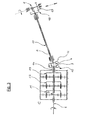
US 5974615 . - L'invention sera mieux comprise, et d'autres caractéristiques et avantages de l'invention apparaîtront à la lumière de la description qui suit d'exemples de réalisation d'appareils selon l'invention. Cet exemple est donné à titre non limitatif. La description est à lire en relation avec les dessins annexés dans lesquels :
- la
figure 1 est une vue en coupe d'un appareil selon un premier mode de réalisation de l'invention, - la
figure 2 est une vue en coupe partielle d'un appareil selon un deuxième mode de réalisation de l'invention, - la
figure 3 est un schéma cinétique d'un appareil selon l'invention, et - la
figure 4 est une vue de détail de la tête de l'appareil de lafigure 1 . - L'appareil représenté sur la
figure 1 est du type contre-angle. Il comprend une tête dans laquelle l'outil est maintenu et entraîné en rotation et un manche fixé à la tête. A l'intérieur du manche sont positionnés les éléments des moyens de transmission, réalisés comme suit. - Un axe d'entrée 1 est entraîné en rotation par un moteur non représenté, dont la vitesse est classiquement réglable, par exemple entre 1000 et 40 000 tours / minutes.
- Le premier mouvement est obtenu comme suit. L'axe 1 entraîne un premier axe de transmission 2 au travers d'un jeu de pignons 3 et 4. L'axe 2 est muni à son extrémité côté tête du contre-angle, d'un maneton 5 excentré par rapport à l'axe de rotation de l'axe de transmission 2. Dans l'exemple représenté, le maneton est excentré de 0,2 mm, ce qui permet d'obtenir un mouvement de va et vient de l'outil d'une amplitude de 0,4 mm. Le maneton 5 coopère avec une gorge 6 pratiquée à l'extérieur d'une douille 7 contenant le système de serrage et de rétention de l'instrument canalaire. Cette douille 7 est guidée en translation et en rotation par les coussinets 8a et 8b.
- La rotation du moteur, donc de l'axe 1 puis de l'axe 2, va ainsi provoquer un mouvement de va et vient de la douille 7 ainsi que du système de serrage et de l'instrument canalaire qu'elle contient.
- Le deuxième mouvement est obtenu comme suit. L'axe 1 entraine également un réducteur planétaire (ou train épicycloïdal) à trois étages 9 au travers d'un engrenage 10. Dans le réducteur, trois portes-satellites 11, 12 et 13 sont guidés et tournent autour de l'axe central 1, le porte- satellites de sortie 13 est en plus guidé dans un palier 14 constitué par exemple de deux roulements à billes. Un pignon 15 est fixé solidairement sur l'extrémité du porte-satellites de sortie 13 et engrène avec un pignon 16 solidaire d'un deuxième axe de transmission 17 positionné concentriquement à l'axe 2. A l'autre extrémité de l'axe 17, est fixé solidairement un pignon 18 qui engrène avec un pignon 19 fixé solidairement sur la douille 7.
- La rotation du moteur, donc de l'axe 2 puis de l'axe 17, va ainsi provoquer un mouvement de rotation à vitesse réduite de la douille 7 ainsi que du système de serrage et de l'instrument canalaire qu'elle contient.
- Dans l'exemple représenté, le réducteur 9 est constitué d'une couronne fixe C munie d'un engrenage à denture intérieure de 39 dents, et de trois étages de réduction dont les pignons d'entrée A comportent quinze dents et dont les pignons satellites B comporte douze dents. La liaison entre les axes 1 et 2 est constituée de deux pignons 3 et 4 ayant le même nombre de dents. La liaison entre le porte-satellites de sortie 13 et l'axe 17 est constituée de deux pignons 15 et 16 ayant le même nombre de dents. La liaison entre l'axe 17 et la douille 7 contenant l'instrument canalaire et son système de serrage, est constitué d'un pignon menant 18 de dix dents et d'un pignon mené 19 de quatorze dents. Dans ces conditions, le rapport de réduction de vitesse entre l'axe d'entrée 1 et la douille 7 est égal à :

- Ainsi, quand on règle la vitesse de rotation de l'axe 1 (vitesse du moteur) à 5000 tours par minute, l'instrument canalaire fixé dans la tête du contre-angle va tourner à 5000 / R = 76 tours par minute tout en ayant un mouvement axial de va et vient de 5000 aller et retour par minute pour une course de 0,4 mm.
- Il est bien évident que le mode de réalisation de la
figure 1 n'est donné qu'à titre d'exemple, et de nombreuses variantes sont envisageables. - Par exemple, le rapport de réduction peut être ajusté de différentes manières : le réducteur 9 peut avoir d'autres rapports de réduction, avec plus ou moins d'étages de réduction planétaire ; le nombre de dents des pignons A, B et C pourrait être différent pour chacun des étages du réducteur à planétaire ; les couples de pignons 3 et 4 ou/et 15 et 16 peuvent avoir des nombres de dents différents, et donc des rapports de réduction différents de 1.
- Le but d'un appareil selon l'invention est d'obtenir à partir d'une vitesse de rotation d'entrée, deux mouvements, l'un rotatif, l'autre linéaire alternatif, dont les plages de fréquence sont différentes, et de préférence très différentes.
- Egalement, les couples de pignons 3 et 4 ou/et 15 et 16 sont indispensables dans l'exemple représenté dans la mesure où l'appareil est de type contre-angle avec un manche coudé. Toutefois, ces couples de pignon pourraient être supprimés dans le cas d'une pièce à main droite où l'axe d'entrée 1, l'axe de sortie du porte-satellites 13, les axes d'entraînement 2, 17 ont un même axe de rotation.
- Il est à noter que la plupart des moteurs de dentisterie sont réglables entre 1000 et 40000 tours par minute. Pour utiliser le contre-angle décrit dans les conditions décrites ci-dessus, le dentiste doit donc régler la vitesse de son moteur à 5000 tours par minute ce qui est une contrainte puisque en général le dentiste laisse son moteur réglé à 40000 tours par minute, et fait ensuite confiance aux rapports de réduction ou de multiplication des ses différents contre-angles pour ajuster la vitesse de l'outil à la valeur correcte.
- Aussi, une configuration particulièrement intéressante de la présente invention consiste à utiliser un moteur dont la vitesse est de 40000 tours par minute, ce qui évite au dentiste d'avoir à modifier le réglage de la vitesse de son moteur. La vitesse de rotation et la fréquence de va et vient de l'instrument peuvent être similaires à celle de l'exemple précédent, en adaptant les éléments du réducteur et le nombre de dents des différents pignons.
- Pour cela, il est possible d'utiliser par exemple :
- un réducteur de 4 étages de réduction avec :
- ➢ une couronne fixe C comprenant 39 dents pour les deux premiers étages et 41 dents pour les deux derniers étages,
- ➢ des pignons d'entrée A comprenant 19 dents pour les deux premiers étages et 9 dents pour les deux derniers étages
- ➢ des pignons satellite B comprenant 10 dents pour les deux premiers étages et 16 dents pour les deux derniers étages,
- un pignon 3 de 14 dents et un pignon 4 de 12 dents,
- un pignon 15 de 20 dents et un pignon 16 de 24 dents, et
- un pignon 18 de 9 dents et un pignon 19 de 14 dents.
- Si la vitesse de l'axe 1 est de 40000 tours / min et si l'axe 2 est entraîné par le porte-satellites de sortie du deuxième étage, la vitesse de rotation de l'axe 2, c'est-à-dire le nombre de va et vient appliqués à l'instrument canalaire, est égale à : 40000 X (19/(19+39))2 X 14/12 = 5007,93
- Si la vitesse de l'axe 1 est de 40000 tours / min et si l'axe 17 est entraîné par le porte-satellites de sortie du quatrième étage, la vitesse de rotation de la douille 7 et de l'instrument canalaire est égale à :

- On voit donc que l'invention offre des possibilités multiples d'obtenir, à partir d'une vitesse de rotation d'entrée, deux mouvements, l'un de va et vient axial, l'autre rotatif, dans des plages de vitesses ou fréquences qui peuvent être très différentes l'une de l'autre.
- Dans les exemples décrit ci-dessus, le mouvement de va et vient axial est plus rapide que le mouvement rotatif mais on peut noter que le même principe permet également d'obtenir un mouvement de va et vient plus lent que le mouvement de rotation ; il suffit pour cela d'intervertir les prises de mouvement en sortie du réducteur 9.
- Selon la même conception, on peut obtenir plus de deux mouvements simultanés, il suffit de connecter d'autres axes de transmission à d'autres étages de réduction planétaire du même réducteur. Un mouvement additionnel pourrait par exemple être utilisé pour entraîner une pompe d'amenée d'un fluide au niveau de la tête de l'appareil ou au niveau de la zone de travail de l'outil.
- La
figure 1 présente un mode de réalisation de l'invention particulièrement adapté à l'entraînement d'un outil à manche normalisé, maintenu par un système de serrage classique à pince. - La
figure 2 présente un mode de réalisation de l'invention particulièrement adapté à l'entraînement d'un outil à manche spécifique muni de son propre engrenage 19a et de sa propre gorge 6a. Par rapport à l'appareil de lafigure 1 , l'appareil de lafigure 2 ne comprend pas de douille ni de système de serrage de l'outil. Le pignon 18 entraîne directement le pignon 19a de l'outil et le maneton 5 coopère directement avec une gorge 6a prévue à cet effet sur le manche de l'outil. Ainsi, la masse à entraîner en mouvement est limitée à la masse de l'outil. Elle est donc beaucoup plus légère que celle d'un système à manche normalisé, surtout si le manche spécifique est réalisé en plastique.
Claims (9)
- Appareil pour entraîner en mouvement des outils utilisés en chirurgie, notamment en chirurgie dentaire, appareil composé d'une tête dans laquelle est fixé un outil, d'un manche sur lequel est fixée la tête, et des moyens de transmission de mouvement d'un moteur jusqu'à l'outil, les moyens de transmission comprenant un premier axe de transmission (2) pour transmettre un premier mouvement à une première fréquence et un deuxième axe de transmission (17) pour transmettre un deuxième mouvement à une deuxième fréquence, caractérisé en ce que la première fréquence étant différente de la deuxième fréquence dans un rapport 20 à 120.
- Appareil selon la revendication 1, dans lequel le premier mouvement est un mouvement alternatif de translation et dans lequel le deuxième mouvement est un mouvement de rotation.
- Appareil selon l'une des revendications précédentes, dans lequel le premier axe de transmission et le deuxième axe de transmission sont partiellement ou totalement coaxiaux.
- Appareil selon l'une des revendications 2 à 3, dans lequel :• une douille (7) maintient et entraîne en mouvement l'outil dans la tête de l'appareil,• le premier axe d'entraînement (2) comprend à une extrémité un maneton (5) excentrique adapté pour coopérer avec une gorge (6) de la douille (7), de sorte qu'un mouvement de rotation du premier axe d'entraînement génère le mouvement alternatif de va et vient de la douille.
- Appareil selon l'une des revendications 2 à 3, adapté pour entraîner en rotation un outil comprenant un manche équipé d'un engrenage (19a) et d'une gorge (6a), dans lequel le premier axe d'entraînement (2) comprend à une extrémité un maneton (5) excentrique adapté pour coopérer avec la gorge du manche de l'outil.
- Appareil selon l'une des revendications précédentes, dans lequel les moyens d'entraînement comprennent également un réducteur de vitesse, un premier arbre du réducteur étant utilisé pour entraîner en rotation le premier axe de transmission et générer le premier mouvement, et un deuxième arbre du réducteur étant utilisé pour entraîner en rotation le deuxième axe de transmission et générer le deuxième mouvement.
- Appareil selon la revendication 6, dans lequel le réducteur est un train épicycloïdal, comprenant un ou plusieurs étages de réduction.
- Appareil selon la revendication 7, dans lequel :• le premier arbre du réducteur est un arbre d'entrée ou un arbre intermédiaire du réducteur et / ou• le deuxième arbre du réducteur est un arbre intermédiaire ou un arbre de sortie du réducteur.
- Appareil selon l'une des revendications précédentes, dans lequel les moyens de transmission sont également adaptés pour générer plus de deux mouvements.
Applications Claiming Priority (2)
| Application Number | Priority Date | Filing Date | Title |
|---|---|---|---|
| FR1050315A FR2955243B1 (fr) | 2010-01-19 | 2010-01-19 | Appareil pour entrainer en mouvement des outils utilises en chirurgie |
| PCT/FR2011/050080 WO2011089348A1 (fr) | 2010-01-19 | 2011-01-18 | Appareil pour entraîner en mouvement des outils utilisés en chirurgie |
Publications (2)
| Publication Number | Publication Date |
|---|---|
| EP2525734A1 EP2525734A1 (fr) | 2012-11-28 |
| EP2525734B1 true EP2525734B1 (fr) | 2015-03-25 |
Family
ID=42634854
Family Applications (1)
| Application Number | Title | Priority Date | Filing Date |
|---|---|---|---|
| EP11704651.6A Active EP2525734B1 (fr) | 2010-01-19 | 2011-01-18 | Appareil pour entraîner en mouvement des outils utilisés en chirurgie |
Country Status (5)
| Country | Link |
|---|---|
| US (1) | US20130101958A1 (fr) |
| EP (1) | EP2525734B1 (fr) |
| JP (1) | JP2013517079A (fr) |
| FR (1) | FR2955243B1 (fr) |
| WO (1) | WO2011089348A1 (fr) |
Cited By (1)
| Publication number | Priority date | Publication date | Assignee | Title |
|---|---|---|---|---|
| CN106974736A (zh) * | 2011-11-21 | 2017-07-25 | W和H牙科产品比莫斯有限公司 | 用于医疗工具尤其是牙科或外科工具的驱动装置 |
Families Citing this family (8)
| Publication number | Priority date | Publication date | Assignee | Title |
|---|---|---|---|---|
| JP5840924B2 (ja) * | 2011-11-09 | 2016-01-06 | 長田電機工業株式会社 | 歯科治療用マイクロモータハンドピース |
| JP5785929B2 (ja) * | 2012-12-21 | 2015-09-30 | 株式会社モリタ製作所 | 歯科用ハンドピース |
| EP3763318B1 (fr) * | 2013-12-10 | 2022-03-30 | Dentsply Sirona Inc. | Pièce à main multidirectionnelle |
| EP2910215B1 (fr) * | 2014-02-20 | 2018-11-07 | W & H Dentalwerk Bürmoos GmbH | Instrument manuel médical, en particulier dentaire |
| US20170245960A1 (en) * | 2014-09-30 | 2017-08-31 | Matthew GHADAMI | Endodontic handpiece with rotational and vertical motion |
| FR3028172B1 (fr) * | 2014-11-07 | 2016-11-25 | Micro Mega Int Mft | Tete de contre angle |
| DE102015214081A1 (de) * | 2015-07-24 | 2017-01-26 | Sirona Dental Systems Gmbh | Zahnärztliches Präparationsinstrument für ein abwechselnd umkehrbar rotierendes Werkzeug |
| CN113007280A (zh) * | 2021-02-23 | 2021-06-22 | 常州赛乐医疗技术有限公司 | 一种增速牙科弯手机 |
Family Cites Families (7)
| Publication number | Priority date | Publication date | Assignee | Title |
|---|---|---|---|---|
| US5145369A (en) * | 1990-04-23 | 1992-09-08 | L. Paul Lustig | Dental tool driving apparatus having rotating and roto-reciprocating motions |
| DE19627752A1 (de) * | 1996-07-10 | 1998-01-15 | Braun Ag | Elektrische Zahnbürste |
| JP4224745B2 (ja) * | 1999-08-27 | 2009-02-18 | マニー株式会社 | 歯科用コントラアングルハンドピース |
| JP4942866B2 (ja) * | 2000-08-29 | 2012-05-30 | マニー株式会社 | 歯科用ハンドピース |
| DE10255120A1 (de) * | 2002-11-26 | 2004-06-03 | Kaltenbach & Voigt Gmbh & Co. Kg | Ärztlichees oder zahnärztliches Handstück mit mehrstufiger Getriebeanordnung |
| FR2849767B1 (fr) | 2003-01-15 | 2006-02-03 | Micro Mega Int Mfg Sa | Perfectionnement aux instruments dentaires mecanises notamment aux instruments d'endodontie et piece a main, dit contre-angle adapte pour recevoir de maniere amovible de tel instruments |
| US8172572B2 (en) * | 2009-06-24 | 2012-05-08 | Redent-Nova Ltd. | Dental tool displacement apparatus with slow rotational motion |
-
2010
- 2010-01-19 FR FR1050315A patent/FR2955243B1/fr not_active Expired - Fee Related
-
2011
- 2011-01-18 WO PCT/FR2011/050080 patent/WO2011089348A1/fr not_active Ceased
- 2011-01-18 JP JP2012549398A patent/JP2013517079A/ja active Pending
- 2011-01-18 EP EP11704651.6A patent/EP2525734B1/fr active Active
- 2011-01-18 US US13/520,945 patent/US20130101958A1/en not_active Abandoned
Cited By (2)
| Publication number | Priority date | Publication date | Assignee | Title |
|---|---|---|---|---|
| CN106974736A (zh) * | 2011-11-21 | 2017-07-25 | W和H牙科产品比莫斯有限公司 | 用于医疗工具尤其是牙科或外科工具的驱动装置 |
| CN106974736B (zh) * | 2011-11-21 | 2019-06-28 | W和H牙科产品比莫斯有限公司 | 用于医疗工具尤其是牙科或外科工具的驱动装置 |
Also Published As
| Publication number | Publication date |
|---|---|
| US20130101958A1 (en) | 2013-04-25 |
| FR2955243B1 (fr) | 2013-01-18 |
| WO2011089348A1 (fr) | 2011-07-28 |
| EP2525734A1 (fr) | 2012-11-28 |
| JP2013517079A (ja) | 2013-05-16 |
| FR2955243A1 (fr) | 2011-07-22 |
Similar Documents
| Publication | Publication Date | Title |
|---|---|---|
| WO2011089348A1 (fr) | Appareil pour entraîner en mouvement des outils utilisés en chirurgie | |
| EP2618772B1 (fr) | Instrument endodontique dont la partie active présente une fente formant un passage pour un fluide | |
| EP1761199B1 (fr) | Instrument dentaire a ultrasons | |
| US20090136896A1 (en) | Dental apparatus for shaping and cleaning a root canal | |
| EP3204626B1 (fr) | Transmission spinale compacte | |
| FR3018712A1 (fr) | Outil de percage a deux moteurs coaxiaux | |
| FR2533286A1 (fr) | Dispositif pour la conversion de mouvements de rotation dans un seul sens en mouvements de rotation alternes et utilisation dudit dispositif | |
| CA2980430A1 (fr) | Reducteur de vitesse a deux lignes intermediaires de transmission | |
| EP1519691A1 (fr) | Contre-angle pour outils rotatifs utilises en chirurgie, notamment en chirurgie dentaire | |
| CA2656727A1 (fr) | Fraise a usage dentaire et a inertie modulee | |
| EP0281847B1 (fr) | Pièce à main dentaire | |
| EP0936382A1 (fr) | Dispositif de réduction de vitesse de rotation | |
| EP0185400B1 (fr) | Dispositif de réduction ou multiplication de vitesse d'une pièce à main dentaire | |
| EP0054484B2 (fr) | Procédé de traitement de l'extrémité des fibres naturelles pour brosses à dents | |
| FR2645430A1 (fr) | Contre-angle d'endodontie | |
| EP3274610A1 (fr) | Boîte à engrenages comportant un réducteur amélioré | |
| EP0181669A1 (fr) | Pièce à main dentaire, notamment contre-angle | |
| FR2530454A1 (fr) | Moteur a air a deux plages de vitesse distinctes pour l'entrainement de pieces rotatives de dentisterie | |
| FR3036609A1 (fr) | Appareil d'entrainement en rotation alternative d'un instrument canalaire | |
| FR3011053A1 (fr) | Dispositif reducteur de vitesse angulaire | |
| FR2799113A1 (fr) | Piece a main dentaire a gestion mecanique du couple limite de debrayage | |
| WO2024051946A1 (fr) | Équipement porte-instrument apte à entraîner en rotation un instrument endodontique, et dispositif endodontique comprenant un tel équipement | |
| WO2012076420A1 (fr) | Dispositif endodontique, destiné à la mise en forme d'un canal dentaire et/ou à la réalisation d'un logement de tenon | |
| FR2611483A1 (fr) | Piece a main dentaire | |
| FR2838494A1 (fr) | Dispositif permettant de transmettre les mouvements de changement de vitesse et de selection depuis des motoreducteurs a un doigt de commande |
Legal Events
| Date | Code | Title | Description |
|---|---|---|---|
| PUAI | Public reference made under article 153(3) epc to a published international application that has entered the european phase |
Free format text: ORIGINAL CODE: 0009012 |
|
| 17P | Request for examination filed |
Effective date: 20120820 |
|
| AK | Designated contracting states |
Kind code of ref document: A1 Designated state(s): AL AT BE BG CH CY CZ DE DK EE ES FI FR GB GR HR HU IE IS IT LI LT LU LV MC MK MT NL NO PL PT RO RS SE SI SK SM TR |
|
| DAX | Request for extension of the european patent (deleted) | ||
| GRAP | Despatch of communication of intention to grant a patent |
Free format text: ORIGINAL CODE: EPIDOSNIGR1 |
|
| INTG | Intention to grant announced |
Effective date: 20140725 |
|
| GRAS | Grant fee paid |
Free format text: ORIGINAL CODE: EPIDOSNIGR3 |
|
| GRAA | (expected) grant |
Free format text: ORIGINAL CODE: 0009210 |
|
| AK | Designated contracting states |
Kind code of ref document: B1 Designated state(s): AL AT BE BG CH CY CZ DE DK EE ES FI FR GB GR HR HU IE IS IT LI LT LU LV MC MK MT NL NO PL PT RO RS SE SI SK SM TR |
|
| REG | Reference to a national code |
Ref country code: GB Ref legal event code: FG4D Free format text: NOT ENGLISH |
|
| REG | Reference to a national code |
Ref country code: CH Ref legal event code: EP |
|
| REG | Reference to a national code |
Ref country code: IE Ref legal event code: FG4D Free format text: LANGUAGE OF EP DOCUMENT: FRENCH |
|
| REG | Reference to a national code |
Ref country code: DE Ref legal event code: R096 Ref document number: 602011014997 Country of ref document: DE Effective date: 20150507 |
|
| REG | Reference to a national code |
Ref country code: AT Ref legal event code: REF Ref document number: 717382 Country of ref document: AT Kind code of ref document: T Effective date: 20150515 |
|
| REG | Reference to a national code |
Ref country code: CH Ref legal event code: NV Representative=s name: MICHELI AND CIE SA, CH |
|
| PG25 | Lapsed in a contracting state [announced via postgrant information from national office to epo] |
Ref country code: LT Free format text: LAPSE BECAUSE OF FAILURE TO SUBMIT A TRANSLATION OF THE DESCRIPTION OR TO PAY THE FEE WITHIN THE PRESCRIBED TIME-LIMIT Effective date: 20150325 Ref country code: HR Free format text: LAPSE BECAUSE OF FAILURE TO SUBMIT A TRANSLATION OF THE DESCRIPTION OR TO PAY THE FEE WITHIN THE PRESCRIBED TIME-LIMIT Effective date: 20150325 Ref country code: FI Free format text: LAPSE BECAUSE OF FAILURE TO SUBMIT A TRANSLATION OF THE DESCRIPTION OR TO PAY THE FEE WITHIN THE PRESCRIBED TIME-LIMIT Effective date: 20150325 Ref country code: SE Free format text: LAPSE BECAUSE OF FAILURE TO SUBMIT A TRANSLATION OF THE DESCRIPTION OR TO PAY THE FEE WITHIN THE PRESCRIBED TIME-LIMIT Effective date: 20150325 |
|
| REG | Reference to a national code |
Ref country code: AT Ref legal event code: MK05 Ref document number: 717382 Country of ref document: AT Kind code of ref document: T Effective date: 20150325 |
|
| REG | Reference to a national code |
Ref country code: LT Ref legal event code: MG4D |
|
| PG25 | Lapsed in a contracting state [announced via postgrant information from national office to epo] |
Ref country code: LV Free format text: LAPSE BECAUSE OF FAILURE TO SUBMIT A TRANSLATION OF THE DESCRIPTION OR TO PAY THE FEE WITHIN THE PRESCRIBED TIME-LIMIT Effective date: 20150325 Ref country code: RS Free format text: LAPSE BECAUSE OF FAILURE TO SUBMIT A TRANSLATION OF THE DESCRIPTION OR TO PAY THE FEE WITHIN THE PRESCRIBED TIME-LIMIT Effective date: 20150325 Ref country code: GR Free format text: LAPSE BECAUSE OF FAILURE TO SUBMIT A TRANSLATION OF THE DESCRIPTION OR TO PAY THE FEE WITHIN THE PRESCRIBED TIME-LIMIT Effective date: 20150626 |
|
| PG25 | Lapsed in a contracting state [announced via postgrant information from national office to epo] |
Ref country code: NL Free format text: LAPSE BECAUSE OF FAILURE TO SUBMIT A TRANSLATION OF THE DESCRIPTION OR TO PAY THE FEE WITHIN THE PRESCRIBED TIME-LIMIT Effective date: 20150325 |
|
| PG25 | Lapsed in a contracting state [announced via postgrant information from national office to epo] |
Ref country code: ES Free format text: LAPSE BECAUSE OF FAILURE TO SUBMIT A TRANSLATION OF THE DESCRIPTION OR TO PAY THE FEE WITHIN THE PRESCRIBED TIME-LIMIT Effective date: 20150325 Ref country code: SK Free format text: LAPSE BECAUSE OF FAILURE TO SUBMIT A TRANSLATION OF THE DESCRIPTION OR TO PAY THE FEE WITHIN THE PRESCRIBED TIME-LIMIT Effective date: 20150325 Ref country code: CZ Free format text: LAPSE BECAUSE OF FAILURE TO SUBMIT A TRANSLATION OF THE DESCRIPTION OR TO PAY THE FEE WITHIN THE PRESCRIBED TIME-LIMIT Effective date: 20150325 Ref country code: RO Free format text: LAPSE BECAUSE OF FAILURE TO SUBMIT A TRANSLATION OF THE DESCRIPTION OR TO PAY THE FEE WITHIN THE PRESCRIBED TIME-LIMIT Effective date: 20150325 Ref country code: EE Free format text: LAPSE BECAUSE OF FAILURE TO SUBMIT A TRANSLATION OF THE DESCRIPTION OR TO PAY THE FEE WITHIN THE PRESCRIBED TIME-LIMIT Effective date: 20150325 Ref country code: PT Free format text: LAPSE BECAUSE OF FAILURE TO SUBMIT A TRANSLATION OF THE DESCRIPTION OR TO PAY THE FEE WITHIN THE PRESCRIBED TIME-LIMIT Effective date: 20150727 |
|
| PG25 | Lapsed in a contracting state [announced via postgrant information from national office to epo] |
Ref country code: PL Free format text: LAPSE BECAUSE OF FAILURE TO SUBMIT A TRANSLATION OF THE DESCRIPTION OR TO PAY THE FEE WITHIN THE PRESCRIBED TIME-LIMIT Effective date: 20150325 Ref country code: AT Free format text: LAPSE BECAUSE OF FAILURE TO SUBMIT A TRANSLATION OF THE DESCRIPTION OR TO PAY THE FEE WITHIN THE PRESCRIBED TIME-LIMIT Effective date: 20150325 Ref country code: IS Free format text: LAPSE BECAUSE OF FAILURE TO SUBMIT A TRANSLATION OF THE DESCRIPTION OR TO PAY THE FEE WITHIN THE PRESCRIBED TIME-LIMIT Effective date: 20150725 |
|
| REG | Reference to a national code |
Ref country code: DE Ref legal event code: R097 Ref document number: 602011014997 Country of ref document: DE |
|
| REG | Reference to a national code |
Ref country code: FR Ref legal event code: PLFP Year of fee payment: 6 |
|
| PG25 | Lapsed in a contracting state [announced via postgrant information from national office to epo] |
Ref country code: DK Free format text: LAPSE BECAUSE OF FAILURE TO SUBMIT A TRANSLATION OF THE DESCRIPTION OR TO PAY THE FEE WITHIN THE PRESCRIBED TIME-LIMIT Effective date: 20150325 |
|
| PLBE | No opposition filed within time limit |
Free format text: ORIGINAL CODE: 0009261 |
|
| STAA | Information on the status of an ep patent application or granted ep patent |
Free format text: STATUS: NO OPPOSITION FILED WITHIN TIME LIMIT |
|
| 26N | No opposition filed |
Effective date: 20160105 |
|
| REG | Reference to a national code |
Ref country code: DE Ref legal event code: R082 Ref document number: 602011014997 Country of ref document: DE Representative=s name: HERNANDEZ, YORCK, DIPL.-ING., DE |
|
| PG25 | Lapsed in a contracting state [announced via postgrant information from national office to epo] |
Ref country code: SI Free format text: LAPSE BECAUSE OF FAILURE TO SUBMIT A TRANSLATION OF THE DESCRIPTION OR TO PAY THE FEE WITHIN THE PRESCRIBED TIME-LIMIT Effective date: 20150325 Ref country code: BE Free format text: LAPSE BECAUSE OF NON-PAYMENT OF DUE FEES Effective date: 20160131 |
|
| PG25 | Lapsed in a contracting state [announced via postgrant information from national office to epo] |
Ref country code: LU Free format text: LAPSE BECAUSE OF FAILURE TO SUBMIT A TRANSLATION OF THE DESCRIPTION OR TO PAY THE FEE WITHIN THE PRESCRIBED TIME-LIMIT Effective date: 20160118 |
|
| GBPC | Gb: european patent ceased through non-payment of renewal fee |
Effective date: 20160118 |
|
| PG25 | Lapsed in a contracting state [announced via postgrant information from national office to epo] |
Ref country code: MC Free format text: LAPSE BECAUSE OF FAILURE TO SUBMIT A TRANSLATION OF THE DESCRIPTION OR TO PAY THE FEE WITHIN THE PRESCRIBED TIME-LIMIT Effective date: 20150325 |
|
| PG25 | Lapsed in a contracting state [announced via postgrant information from national office to epo] |
Ref country code: GB Free format text: LAPSE BECAUSE OF NON-PAYMENT OF DUE FEES Effective date: 20160118 |
|
| REG | Reference to a national code |
Ref country code: IE Ref legal event code: MM4A |
|
| REG | Reference to a national code |
Ref country code: FR Ref legal event code: PLFP Year of fee payment: 7 |
|
| PG25 | Lapsed in a contracting state [announced via postgrant information from national office to epo] |
Ref country code: IE Free format text: LAPSE BECAUSE OF NON-PAYMENT OF DUE FEES Effective date: 20160118 |
|
| PG25 | Lapsed in a contracting state [announced via postgrant information from national office to epo] |
Ref country code: MT Free format text: LAPSE BECAUSE OF FAILURE TO SUBMIT A TRANSLATION OF THE DESCRIPTION OR TO PAY THE FEE WITHIN THE PRESCRIBED TIME-LIMIT Effective date: 20150325 |
|
| REG | Reference to a national code |
Ref country code: FR Ref legal event code: PLFP Year of fee payment: 8 |
|
| PG25 | Lapsed in a contracting state [announced via postgrant information from national office to epo] |
Ref country code: CY Free format text: LAPSE BECAUSE OF FAILURE TO SUBMIT A TRANSLATION OF THE DESCRIPTION OR TO PAY THE FEE WITHIN THE PRESCRIBED TIME-LIMIT Effective date: 20150325 Ref country code: SM Free format text: LAPSE BECAUSE OF FAILURE TO SUBMIT A TRANSLATION OF THE DESCRIPTION OR TO PAY THE FEE WITHIN THE PRESCRIBED TIME-LIMIT Effective date: 20150325 Ref country code: HU Free format text: LAPSE BECAUSE OF FAILURE TO SUBMIT A TRANSLATION OF THE DESCRIPTION OR TO PAY THE FEE WITHIN THE PRESCRIBED TIME-LIMIT; INVALID AB INITIO Effective date: 20110118 |
|
| PG25 | Lapsed in a contracting state [announced via postgrant information from national office to epo] |
Ref country code: MK Free format text: LAPSE BECAUSE OF FAILURE TO SUBMIT A TRANSLATION OF THE DESCRIPTION OR TO PAY THE FEE WITHIN THE PRESCRIBED TIME-LIMIT Effective date: 20150325 Ref country code: TR Free format text: LAPSE BECAUSE OF FAILURE TO SUBMIT A TRANSLATION OF THE DESCRIPTION OR TO PAY THE FEE WITHIN THE PRESCRIBED TIME-LIMIT Effective date: 20150325 Ref country code: NO Free format text: LAPSE BECAUSE OF NON-PAYMENT OF DUE FEES Effective date: 20150625 |
|
| PG25 | Lapsed in a contracting state [announced via postgrant information from national office to epo] |
Ref country code: BG Free format text: LAPSE BECAUSE OF FAILURE TO SUBMIT A TRANSLATION OF THE DESCRIPTION OR TO PAY THE FEE WITHIN THE PRESCRIBED TIME-LIMIT Effective date: 20150325 |
|
| PG25 | Lapsed in a contracting state [announced via postgrant information from national office to epo] |
Ref country code: AL Free format text: LAPSE BECAUSE OF FAILURE TO SUBMIT A TRANSLATION OF THE DESCRIPTION OR TO PAY THE FEE WITHIN THE PRESCRIBED TIME-LIMIT Effective date: 20150325 |
|
| PGFP | Annual fee paid to national office [announced via postgrant information from national office to epo] |
Ref country code: FR Payment date: 20230126 Year of fee payment: 13 Ref country code: CH Payment date: 20230130 Year of fee payment: 13 |
|
| PGFP | Annual fee paid to national office [announced via postgrant information from national office to epo] |
Ref country code: IT Payment date: 20230110 Year of fee payment: 13 Ref country code: DE Payment date: 20230112 Year of fee payment: 13 |
|
| REG | Reference to a national code |
Ref country code: DE Ref legal event code: R119 Ref document number: 602011014997 Country of ref document: DE |
|
| REG | Reference to a national code |
Ref country code: CH Ref legal event code: PL |
|
| PG25 | Lapsed in a contracting state [announced via postgrant information from national office to epo] |
Ref country code: DE Free format text: LAPSE BECAUSE OF NON-PAYMENT OF DUE FEES Effective date: 20240801 |
|
| PG25 | Lapsed in a contracting state [announced via postgrant information from national office to epo] |
Ref country code: FR Free format text: LAPSE BECAUSE OF NON-PAYMENT OF DUE FEES Effective date: 20240131 |
|
| PG25 | Lapsed in a contracting state [announced via postgrant information from national office to epo] |
Ref country code: CH Free format text: LAPSE BECAUSE OF NON-PAYMENT OF DUE FEES Effective date: 20240131 |
|
| PG25 | Lapsed in a contracting state [announced via postgrant information from national office to epo] |
Ref country code: FR Free format text: LAPSE BECAUSE OF NON-PAYMENT OF DUE FEES Effective date: 20240131 Ref country code: DE Free format text: LAPSE BECAUSE OF NON-PAYMENT OF DUE FEES Effective date: 20240801 Ref country code: CH Free format text: LAPSE BECAUSE OF NON-PAYMENT OF DUE FEES Effective date: 20240131 |
|
| PG25 | Lapsed in a contracting state [announced via postgrant information from national office to epo] |
Ref country code: IT Free format text: LAPSE BECAUSE OF NON-PAYMENT OF DUE FEES Effective date: 20240118 |