EP2525503A1 - Stromleitungskommunikationsmodem, Stromleitungskommunikationssystem, Stromleitungskommunikationsverfahren - Google Patents
Stromleitungskommunikationsmodem, Stromleitungskommunikationssystem, Stromleitungskommunikationsverfahren Download PDFInfo
- Publication number
- EP2525503A1 EP2525503A1 EP20120000138 EP12000138A EP2525503A1 EP 2525503 A1 EP2525503 A1 EP 2525503A1 EP 20120000138 EP20120000138 EP 20120000138 EP 12000138 A EP12000138 A EP 12000138A EP 2525503 A1 EP2525503 A1 EP 2525503A1
- Authority
- EP
- European Patent Office
- Prior art keywords
- power
- power line
- signal
- line communication
- wires
- Prior art date
- Legal status (The legal status is an assumption and is not a legal conclusion. Google has not performed a legal analysis and makes no representation as to the accuracy of the status listed.)
- Granted
Links
Images



Classifications
-
- H—ELECTRICITY
- H04—ELECTRIC COMMUNICATION TECHNIQUE
- H04B—TRANSMISSION
- H04B3/00—Line transmission systems
- H04B3/54—Systems for transmission via power distribution lines
- H04B3/544—Setting up communications; Call and signalling arrangements
-
- H—ELECTRICITY
- H04—ELECTRIC COMMUNICATION TECHNIQUE
- H04B—TRANSMISSION
- H04B3/00—Line transmission systems
- H04B3/54—Systems for transmission via power distribution lines
-
- H—ELECTRICITY
- H04—ELECTRIC COMMUNICATION TECHNIQUE
- H04B—TRANSMISSION
- H04B3/00—Line transmission systems
- H04B3/54—Systems for transmission via power distribution lines
- H04B3/56—Circuits for coupling, blocking, or by-passing of signals
-
- H—ELECTRICITY
- H04—ELECTRIC COMMUNICATION TECHNIQUE
- H04B—TRANSMISSION
- H04B2203/00—Indexing scheme relating to line transmission systems
- H04B2203/54—Aspects of powerline communications not already covered by H04B3/54 and its subgroups
- H04B2203/5429—Applications for powerline communications
- H04B2203/5454—Adapter and plugs
-
- H—ELECTRICITY
- H04—ELECTRIC COMMUNICATION TECHNIQUE
- H04B—TRANSMISSION
- H04B2203/00—Indexing scheme relating to line transmission systems
- H04B2203/54—Aspects of powerline communications not already covered by H04B3/54 and its subgroups
- H04B2203/5462—Systems for power line communications
- H04B2203/5466—Systems for power line communications using three phases conductors
Definitions
- the invention relates to a power line communication modem, to a power line communication system and to a power line communication method.
- Power line communication also called mains communication, power line transmission (PLT), broadband power line (BPL), power band or power line networking (PLN), is a term describing several different systems for using power distribution wires or power lines for simultaneous distribution of data.
- a carrier can communicate voice and data by superimposing an analogue signal over the standard 50 Hz or 60 Hz alternating current (AC).
- AC alternating current
- PLC equipment can use household electrical power wiring as a transmission medium.
- MIMO multiple-input - multiple output schemes
- household power line networks include at least three different wires or lines that are named "phase”, “neutral”, and “protective earth”.
- data is transmitted via those wires by transmitting differential signals on different combination of the wires, e.g. between phase and neutral (PN), phase and protective earth (PE), and/or neutral and protective earth (NE).
- PN phase and neutral
- PE phase and protective earth
- NE neutral and protective earth
- MIMO PLC might influence reception of radio broadcasts or amateur radio broadcast, it is intended to define levels of MIMO feeding in the future.
- Fig. 1 there is depicted schematically a power line communication modem 100 according to an embodiment of the invention.
- the power line communication modem 100 includes a connection element 110 configured to connect the power line communication modem 100 to at least three wires of a power line network 115, e.g. in a household. In many households three of those at least three wires are named "phase" line (P), "neutral” line (N) and “protective earth” line (PE or E).
- P phase line
- N neutral line
- PE or E protective earth
- the power line communication modem 100 further includes a transmitter 120 that is configured to transmit a first signal via a first combination of at least two wires of the at least three wires, e.g. between the phase line and the neutral line (PN), and to transmit a second signal via a second combination of at least two wires of the at least three wires, e.g. between the protective earth line and the phase line (EP) or between the neutral line and the protective earth line (NE).
- PN phase line and the neutral line
- NE neutral line and the protective earth line
- two of the at least three wires might be grouped or connected and the signal is fed between the group of wires and the third wire.
- MIMO multiple-input - multiple output
- phase line e.g. phase line, neutral line and protective earth line
- two lines i.e. phase-neutral (PN), protective earth-phase (EP), neutral-protective earth (NE).
- PN phase-neutral
- EP protective earth-phase
- NE neutral-protective earth
- MIMO-schemes to use all three combinations, i.e. with a first signal at the first combination, a second signal at the second combination and a third signal at the third combination, however, due to Kirchhoff's law only two of them can be used independently at the same time.
- the first, second and third signal generally are fed in differential mode (DM).
- DM differential mode
- the power line communication modem 100 further includes a controller 130 that is adapted to individually control a transmit power of the first signal and the second signal.
- the "transmit power” might also be referred to as “power spectral density (PSD)".
- controller 130 With the help of the controller 130 it is possible to transmit the first signal and second signal with different transmit power.
- Fig. 2 it is schematically depicted that in a step S200 the first signal is transmitted with a first transmit power and in step S202 the second signal is transmitted with a second transmit power.
- the transmit power of the first signal and the second signal is adjusted according to their potential of interference to radio receivers, it is possible to transmit a signal with less radiation with a higher transmit power, resulting in the possibility of using e.g. higher constellations in adaptive OFDM (orthogonal frequency division multiplexing) schemes or simply in resulting in higher signal to noise ratios (SNR) achieving higher bandwidth than when feeding the signals with the same transmit power for all possible combinations.
- SNR signal to noise ratios
- Measurements were undertaken to record the interference potential from MIMO PLC.
- the measurement set-up depicted in Fig. 3 consisted of a Network Analyzer NWA 302 connected with a MIMO PLC probe 304 to the mains of a building 306 via an outlet 308.
- the power supply of the Network Analyzer 302 was isolated from the buildings mains grid.
- the Network Analyzer 302 fed signals into the mains using a MIMO PLC probe 304. All possible potential feeding possibilities (PN, NE, EP) were examined. For comparison common mode (CM) signals were also fed.
- an antenna 310, 312 was located in- or outside the building 306 at various distances d from the injecting outlet 308. Depending on the frequencies of interests a magnetic loop antenna 312 (for frequencies below 30MHz) or a biconal antenna 310 (frequencies between 1MHz and 100MHz) was used.
- the link (cable) 320 from the antenna to the Network Analyzer 302 was filtered from common mode signals. Otherwise the signal ingress into the cable 320 might affect the measurement.
- the outlets 308 used for feeding the signals were arbitrary selected in the building 306.
- Figures 4 and 5 wherein Figure 5 shows only a part of Figure 4 , show the attenuation (the scattering parameter S21 (forward gain) in dB) recorded by the Network Analyzer 302 of more than 100000 measurements for each combination of wires independent of frequency and feeding plug or outlet 308 at several buildings 306.
- Fig. 4 and Fig. 5 the attenuation from feeding to an outlet 308 to the reception of the signals at an antenna 310, 312 is depicted.
- differential mode feeding in EP protection earth line - phase line
- NE neutral line- protective earth line
- PN phase line - neutral line
- the common mode is the dotted line.
- the x-axis shows the S21 parameter from -110dB to -30dB.
- the y-axis shows the cumulative probability of the attenuation.
- the attenuation is higher than 30 dB and for 0% (none) of all values the attenuation is higher than 110 dB.
- the negative sign of the S21 parameter reflects that the signal at the antenna 310, 312 is attenuated as compared to the fed signal at the outlet 308. As more left the lines are in these figures as higher is the attenuation, as lower is the radiation or the interference potential. It can be seen that signals feed in common mode do radiate most.
- Fig. 5 which is zoomed into a part of Fig. 4 , helps in identifying the differences between the 3 differential mode feedings.
- Feeding in EP causes 1.3dB more radiation compared to feeding in PN (phase - neutral).
- Feeding into NE (neutral - protective earth) causes 0.8dB less radiation than feeding to PN (phase - neutral) at the 50%-point.
- power line communication modems can improve their transmission characteristics by adopting their individual feeding power spectral density (PSD).
- PSD power spectral density
- a power line communication system 600 is schematically depicted. It includes the first power line communication modem 100 and a second power line communication modem 610, which are connected via the power line network 115, in Fig. 6 represented by the three lines phase (P), neutral (N) and protective earth (E).
- the first power line communication modem 100 further includes a receiver 620 adapted to receive signals transmitted from a transmitter 630 of the second power line communication modem 610.
- the transmitter 630 of the second power line communication modem is connected via a connecting element 640 of the second power line communication modem 610 to the power line network 115.
- the second power line communication modem 610 further includes a controller 650 adapted to control individually the transmit power of signals that are transmitted by the transmitter 610 via different combinations of wires P, N, PE and a receiver 660 adapted to receive signals transmitted from the first transmitter 120.
- the first power line communication modem 100 might further include a storage unit 666 adapted to store a power difference value and the controller 130 is further adapted to feed the first signal and second signal with respective transmit powers that are distinguished by the stored power difference value.
- a power quotient value might be stored in the storage unit 666 and the controller 130 might be adapted to feed the first signal and the second signal with transmit powers that are distinguished by the stored power quotient value.
- the stored power difference value or the stored power quotient value might be frequency independent, since the measurements did not show any particular frequency dependency of the different radiation properties of the different combinations of wires.
- the stored power difference value or the stored power quotient value might be used as a constant, predetermined value that is not changed during the lifetime of the power line communication modem, which would result in an easy implementation, since no updating is necessary. More sophisticated approaches, however, might include updating of the power difference value or the power quotient value, e.g. for certain particular radiation characteristics of the power line network or for considering amended regulatory limits.
- the controller 130 might be adapted to feed a signal via the combination EP of the protective earth line E and the phase line P with 1 dB less transmit power than a signal via the combination PN of the phase line P and the neutral line N, which reflects the measurement results depicted in Fig. 5 that signals transmitted via the combination PN of the phase line P and the neutral N show a higher attenuation of the received signal of approximately 1dB due to lower radiation than signals transmitted via the combination EP of the protective earth line E and the phase line P.
- the controller 130 might be adapted to feed a signal via the combination NE of the neutral line N and the protective earth line E with 1 dB more transmit power than a signal via the combination PN of the phase line P and the neutral line N, which reflects the measurement results depicted in Fig. 5 that signals transmitted via the combination NE of the neutral line N and the protective earth line E show a higher attenuation of the received signal of approximately 1dB due to lower radiation than signals transmitted via the combination PN of the phase line P and the neutral line N.
- a feeding between the phase line P and the neutral line N is meant to describe a feeding according to single-input single-output (SISO) schemes currently used, i.e. feeding differentially between the phase line P and the neutral line N without termination towards the protective earth line or with a left open connection towards protective earth.
- SISO single-input single-output
- the 1dB difference between the respective transmit powers might also be referred to as a possible power quotient value.
- the first power line communication modem 100 might include a measuring unit 680
- the second power line communication modem 610 might include a measuring unit 690, respectively, adapted to measure the voltages between the at least three lines P, N, E and is further adapted to determine the phase line and the neutral line based on measuring the voltages.
- power line networks 115 where it is not certain, which of the wires is the phase line P and the neutral line N, it is possible to determine the phase line and the neutral line among the wires of the power line network and to adapt the transmit power of the combinations accordingly by the controller 130.
- the supply voltage AC (230 V or 110 V) is present between the phase line P and the neutral line N and between the phase line P and the protective earth line E, whereas between the neutral line N and the protective earth line E the voltage is 0V, it can be determined which of the lines or wires is the phase line P.
- the second power line communication modem 610 might also include a storage unit 695 adapted to perform functions as the storage unit 666 of the first power line communication modem 100.
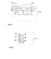
- FIG. 7 shows a star-style MIMO PLC probe 700. It is mainly intended for receiving only.
- the CM choke 702 blocks the common mode current from the star transformers 704.
- the choke 702 simultaneously acts as a transformer which allows the reception of the CM signal.
- the signals on S1, S2 or S3 are directly coupled onto the individual wires P, N, PE.
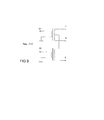
- Figure 8 shows a delta style coupler 800.
- the signals S1, S2 or S3 create the differential voltages U P-N , U N-PE and U PE-P .
- Figure 9 shows a T-style coupler 900 where the first signal is coupled differentially between two of the three wires and the second signal is coupled differentially between one wire and two other wires.
- the couplers are published in ETSI TR 101 562.
- Fig. 10 also the attenuation from feeding to an outlet 308 to the reception of the signals at an antenna 310, 312 is depicted.
- differential mode feeding in EP protection earth line - phase line
- NE neutral line- protective earth line
- PN phase line - neutral line
- the feedings on the T-style coupler 900 are presented using the fat dashed line when feeding on S1 at the T-style coupler 900 (T-stylel) (i.e.
- T-style2 T-style coupier 900
- the x-axis shows the S21 parameter from -78dB to -75dB.
- the y-axis shows the cumulative probability of the attenuation. It can be seen that signals fed in T-style radiate less than the signals fed in delta style.
- Feeding in T-style 1 generates roughly 0.5 dB less radiation compared to feeding in PN (phase - neutral). Feeding into T-style2 causes roughly 1.0 dB less radiation than feeding to PN (phase - neutral) at the 50% point.
- the controller 130 might be adapted to feed a signal with 0.5 dB more transmit power when using a T-style coupler and when the signal is coupled differentially between phase and neutral with a termination of the midpoint between phase and neutral towards protective earth than when coupling the signal between phase and neutral without termination and/or the controller might be adapted to feed a signal with 1 dB more transmit power when using a T-style coupler and when the signal is coupled differentially between protective earth and the midpoint of phase and neutral than when coupling the signal between phase and neutral without termination.
- power line communication modems can improve their transmission characteristics by adopting their individual feeding power spectral density (PSD).
- PSD power spectral density
Landscapes
- Engineering & Computer Science (AREA)
- Power Engineering (AREA)
- Computer Networks & Wireless Communication (AREA)
- Signal Processing (AREA)
- Cable Transmission Systems, Equalization Of Radio And Reduction Of Echo (AREA)
Priority Applications (1)
| Application Number | Priority Date | Filing Date | Title |
|---|---|---|---|
| EP12000138.3A EP2525503B1 (de) | 2011-05-16 | 2012-01-11 | Stromleitungskommunikationsmodem, Stromleitungskommunikationssystem, Stromleitungskommunikationsverfahren |
Applications Claiming Priority (2)
| Application Number | Priority Date | Filing Date | Title |
|---|---|---|---|
| EP11004046 | 2011-05-16 | ||
| EP12000138.3A EP2525503B1 (de) | 2011-05-16 | 2012-01-11 | Stromleitungskommunikationsmodem, Stromleitungskommunikationssystem, Stromleitungskommunikationsverfahren |
Publications (2)
| Publication Number | Publication Date |
|---|---|
| EP2525503A1 true EP2525503A1 (de) | 2012-11-21 |
| EP2525503B1 EP2525503B1 (de) | 2018-03-07 |
Family
ID=45443019
Family Applications (1)
| Application Number | Title | Priority Date | Filing Date |
|---|---|---|---|
| EP12000138.3A Active EP2525503B1 (de) | 2011-05-16 | 2012-01-11 | Stromleitungskommunikationsmodem, Stromleitungskommunikationssystem, Stromleitungskommunikationsverfahren |
Country Status (3)
| Country | Link |
|---|---|
| US (2) | US8902957B2 (de) |
| EP (1) | EP2525503B1 (de) |
| CN (2) | CN105429677B (de) |
Cited By (2)
| Publication number | Priority date | Publication date | Assignee | Title |
|---|---|---|---|---|
| EP2874325A1 (de) * | 2013-11-19 | 2015-05-20 | Devolo AG | Vorrichtung zur MIMO-Einkopplung von Powerline-Signalen über zwei Kanäle in ein Dreileiter-Stromversorgungsnetz |
| CN116032313A (zh) * | 2022-12-15 | 2023-04-28 | 南京邮电大学 | 一种用于电力线通信的t型阻抗匹配耦合器 |
Families Citing this family (13)
| Publication number | Priority date | Publication date | Assignee | Title |
|---|---|---|---|---|
| US20120265355A1 (en) | 2011-04-15 | 2012-10-18 | Power Tagging Technologies, Inc. | System and method for single and multizonal optimization of utility services delivery and utilization |
| US9059842B2 (en) | 2011-06-09 | 2015-06-16 | Astrolink International Llc | System and method for grid based cyber security |
| US10097240B2 (en) | 2013-02-19 | 2018-10-09 | Astrolink International, Llc | System and method for inferring schematic and topological properties of an electrical distribution grid |
| WO2014201410A1 (en) | 2013-06-13 | 2014-12-18 | Astrolink International Llc C/O Lockheed Martin Corporation | Inferring feeder and phase powering a transmitter |
| MX357831B (es) | 2013-06-13 | 2018-07-26 | Astrolink Int Llc | Perdidas no tecnicas en una rejilla electrica publica. |
| CN203787191U (zh) * | 2014-04-22 | 2014-08-20 | 中怡(苏州)科技有限公司 | 电力传输线通信信号通过装置与其信号传输线 |
| US9577707B1 (en) * | 2014-07-14 | 2017-02-21 | Marvell International Ltd. | Method and device for stabilizing impedance on a power-line communication device |
| AU2015338943B2 (en) | 2014-10-30 | 2019-09-12 | Dominion Energy Technologies, Inc. | System and methods for assigning slots and resolving slot conflicts in an electrical distribution grid |
| US9843436B2 (en) * | 2015-06-27 | 2017-12-12 | Intel Corporation | Flexible interconnect architecture |
| US9559752B1 (en) | 2015-09-24 | 2017-01-31 | Qualcomm Incorporated | Switching signal polarity of a network device plug for use in a powerline communication network |
| CN107342793B (zh) * | 2016-04-28 | 2021-06-29 | 松下知识产权经营株式会社 | 电力发送装置、电力接收装置以及电力传送系统 |
| WO2020061744A1 (zh) * | 2018-09-25 | 2020-04-02 | 华为技术有限公司 | 一种plc控制方法和装置 |
| CN110289889B (zh) * | 2019-06-26 | 2021-08-27 | 国网江西省电力有限公司经济技术研究院 | 用于低压电力线载波通信的新型耦合器 |
Citations (3)
| Publication number | Priority date | Publication date | Assignee | Title |
|---|---|---|---|---|
| EP1217760A1 (de) * | 2000-12-11 | 2002-06-26 | Siemens Aktiengesellschaft | Anordnung und Verfahren zur Datenkommunikation in einem Energieverteilungsnetz |
| WO2011001430A2 (en) * | 2009-06-29 | 2011-01-06 | Coppergate Communication Ltd. | Power line communication method and apparatus |
| US20110026621A1 (en) * | 2009-08-03 | 2011-02-03 | Texas Instruments Incorporated | Ofdm transmission methods in three phase modes |
Family Cites Families (13)
| Publication number | Priority date | Publication date | Assignee | Title |
|---|---|---|---|---|
| US7321291B2 (en) * | 2004-10-26 | 2008-01-22 | Current Technologies, Llc | Power line communications system and method of operating the same |
| JP2006094308A (ja) * | 2004-09-27 | 2006-04-06 | Alps Electric Co Ltd | 電力線通信用モデムにおける信号重畳方法及び電力線通信用モデム |
| US7804763B2 (en) * | 2005-04-04 | 2010-09-28 | Current Technologies, Llc | Power line communication device and method |
| EP2800285B1 (de) * | 2006-08-24 | 2019-10-02 | Sony Deutschland Gmbh | Verfahren zum Senden eines Signals in einem Stromnetz, Sendeeinheit, Empfangseinheit und System |
| CN101689043B (zh) * | 2007-05-02 | 2014-05-07 | 西格玛设计以色列有限公司 | 基于户内线缆的多输入多输出(mimo)通信系统 |
| CN101102127B (zh) * | 2007-07-31 | 2010-05-19 | 南京中网通信有限公司 | 电力调制解调器在应急通信中的应用方法 |
| EP2393214B1 (de) | 2007-08-22 | 2020-06-17 | Sony Corporation | Verfahren zur Übertragung eines Signals über ein Stromleitungsnetzwerk, Sender, Empfänger, Stromleitungskommunikationsmodem und Stromleitungskommunikationssystem |
| CN101414852B (zh) * | 2007-10-19 | 2012-08-22 | 弥亚微电子(上海)有限公司 | 用于电力线载波通信的输出耦合及滤波电路 |
| US20090295551A1 (en) * | 2008-05-28 | 2009-12-03 | Dickey John A | Electric power and control communications distribution system |
| EP2157704B1 (de) * | 2008-08-20 | 2012-01-25 | Sony Corporation | Vorrichtung zum Bestimmen eines Gleichtaktsignals in einem Stromleitungs-Kommunikationsnetz |
| CN101520942A (zh) * | 2008-12-26 | 2009-09-02 | 康佳集团股份有限公司 | 一种基于电力线载波通信的电器控制方法及其控制装置 |
| CN101820303A (zh) * | 2010-01-25 | 2010-09-01 | 苏州泰思特电子科技有限公司 | 一种应用于电力线通信网络的辐射噪声测试方法 |
| CN101887095B (zh) * | 2010-07-01 | 2013-11-27 | 苏州泰思特电子科技有限公司 | 一种用于数字式重力计量设备的辐射噪声测试方法 |
-
2012
- 2012-01-11 EP EP12000138.3A patent/EP2525503B1/de active Active
- 2012-05-07 US US13/465,420 patent/US8902957B2/en active Active
- 2012-05-15 CN CN201510647134.7A patent/CN105429677B/zh not_active Expired - Fee Related
- 2012-05-15 CN CN201210160761.4A patent/CN102811074B/zh not_active Expired - Fee Related
-
2014
- 2014-10-28 US US14/525,897 patent/US9667320B2/en active Active
Patent Citations (3)
| Publication number | Priority date | Publication date | Assignee | Title |
|---|---|---|---|---|
| EP1217760A1 (de) * | 2000-12-11 | 2002-06-26 | Siemens Aktiengesellschaft | Anordnung und Verfahren zur Datenkommunikation in einem Energieverteilungsnetz |
| WO2011001430A2 (en) * | 2009-06-29 | 2011-01-06 | Coppergate Communication Ltd. | Power line communication method and apparatus |
| US20110026621A1 (en) * | 2009-08-03 | 2011-02-03 | Texas Instruments Incorporated | Ofdm transmission methods in three phase modes |
Cited By (3)
| Publication number | Priority date | Publication date | Assignee | Title |
|---|---|---|---|---|
| EP2874325A1 (de) * | 2013-11-19 | 2015-05-20 | Devolo AG | Vorrichtung zur MIMO-Einkopplung von Powerline-Signalen über zwei Kanäle in ein Dreileiter-Stromversorgungsnetz |
| US9136909B2 (en) | 2013-11-19 | 2015-09-15 | Devolo Ag | Apparatus for MIMO coupling power line signals into a three-conductor power supply network via two channels |
| CN116032313A (zh) * | 2022-12-15 | 2023-04-28 | 南京邮电大学 | 一种用于电力线通信的t型阻抗匹配耦合器 |
Also Published As
| Publication number | Publication date |
|---|---|
| US20150117503A1 (en) | 2015-04-30 |
| US8902957B2 (en) | 2014-12-02 |
| CN102811074B (zh) | 2015-10-07 |
| CN105429677B (zh) | 2018-03-06 |
| EP2525503B1 (de) | 2018-03-07 |
| CN105429677A (zh) | 2016-03-23 |
| US20120294342A1 (en) | 2012-11-22 |
| CN102811074A (zh) | 2012-12-05 |
| US9667320B2 (en) | 2017-05-30 |
Similar Documents
| Publication | Publication Date | Title |
|---|---|---|
| US9667320B2 (en) | Power line communication modem, power line communication system, power line communication method | |
| CN114008929B (zh) | 用于光伏模块级监测系统内的通信的方法 | |
| US7265664B2 (en) | Power line communications system and method | |
| EP2157704B1 (de) | Vorrichtung zum Bestimmen eines Gleichtaktsignals in einem Stromleitungs-Kommunikationsnetz | |
| US9191068B2 (en) | Method for transmitting a signal via a power line network, transmitter, receiver, power line communication modem and power line communication system | |
| US7962118B2 (en) | Method for transmitting a signal on a power line network, transmitting unit, receiving unit and system | |
| US20070054622A1 (en) | Hybrid power line wireless communication system | |
| EP2154789B1 (de) | Verfahren zum Detektieren einer Einstreuung von einem Kurzwellen-Funksignal auf ein Stromleitungskommunikationssystem und Stromleitungskommunikationsmodem | |
| US9143198B2 (en) | Power line communication method and apparatus | |
| US9479221B2 (en) | Power line communication method and apparatus | |
| JP5853189B2 (ja) | 分岐器 | |
| US7079012B2 (en) | System and method for distributing broadband communication signals over power lines | |
| US20120313764A1 (en) | System for coupling a power line communication device to a power line network | |
| EP2909951B1 (de) | Kommunikationsvorrichtung und verfahren zur übertragung von mindestens zwei parallelen übertragungssignalen | |
| CN101471699A (zh) | 电力线传输 | |
| US10727900B2 (en) | Communication over a communication line | |
| JP2004080441A (ja) | 送信装置及び受信装置 | |
| EP1842297B1 (de) | Kommunikationsvorrichtung und kommunikationsverfahren | |
| Battermann et al. | Influence of PLC transmission on the sensitivity of a short-wave receiving station | |
| US20090124209A1 (en) | Methods and system for configuration of broadband over power lines | |
| CN109728837B (zh) | 一种抵消串扰信号的方法、装置及系统 | |
| EP2696512A1 (de) | System zum Koppeln einer Stromkabelkommunikationsvorrichtung zu einem Stromkabelnetzwerk | |
| Dulay et al. | Performance evaluation of G3 narrowband PLC standard for transmission through single and paired transformer | |
| Battermann et al. | Interference potential of PLC and measurement of mains characteristics | |
| Tahsien et al. | Performance limitations of a 2× 2 MIMO power line communication system impaired by non-white impulsive and non-Gaussian power line noise |
Legal Events
| Date | Code | Title | Description |
|---|---|---|---|
| PUAI | Public reference made under article 153(3) epc to a published international application that has entered the european phase |
Free format text: ORIGINAL CODE: 0009012 |
|
| 17P | Request for examination filed |
Effective date: 20120111 |
|
| AK | Designated contracting states |
Kind code of ref document: A1 Designated state(s): AL AT BE BG CH CY CZ DE DK EE ES FI FR GB GR HR HU IE IS IT LI LT LU LV MC MK MT NL NO PL PT RO RS SE SI SK SM TR |
|
| AX | Request for extension of the european patent |
Extension state: BA ME |
|
| 17Q | First examination report despatched |
Effective date: 20160425 |
|
| STAA | Information on the status of an ep patent application or granted ep patent |
Free format text: STATUS: EXAMINATION IS IN PROGRESS |
|
| GRAP | Despatch of communication of intention to grant a patent |
Free format text: ORIGINAL CODE: EPIDOSNIGR1 |
|
| STAA | Information on the status of an ep patent application or granted ep patent |
Free format text: STATUS: GRANT OF PATENT IS INTENDED |
|
| INTG | Intention to grant announced |
Effective date: 20170726 |
|
| GRAJ | Information related to disapproval of communication of intention to grant by the applicant or resumption of examination proceedings by the epo deleted |
Free format text: ORIGINAL CODE: EPIDOSDIGR1 |
|
| STAA | Information on the status of an ep patent application or granted ep patent |
Free format text: STATUS: EXAMINATION IS IN PROGRESS |
|
| GRAP | Despatch of communication of intention to grant a patent |
Free format text: ORIGINAL CODE: EPIDOSNIGR1 |
|
| STAA | Information on the status of an ep patent application or granted ep patent |
Free format text: STATUS: GRANT OF PATENT IS INTENDED |
|
| INTC | Intention to grant announced (deleted) | ||
| INTG | Intention to grant announced |
Effective date: 20170927 |
|
| GRAS | Grant fee paid |
Free format text: ORIGINAL CODE: EPIDOSNIGR3 |
|
| GRAA | (expected) grant |
Free format text: ORIGINAL CODE: 0009210 |
|
| STAA | Information on the status of an ep patent application or granted ep patent |
Free format text: STATUS: THE PATENT HAS BEEN GRANTED |
|
| AK | Designated contracting states |
Kind code of ref document: B1 Designated state(s): AL AT BE BG CH CY CZ DE DK EE ES FI FR GB GR HR HU IE IS IT LI LT LU LV MC MK MT NL NO PL PT RO RS SE SI SK SM TR |
|
| REG | Reference to a national code |
Ref country code: GB Ref legal event code: FG4D |
|
| REG | Reference to a national code |
Ref country code: CH Ref legal event code: EP Ref country code: AT Ref legal event code: REF Ref document number: 977595 Country of ref document: AT Kind code of ref document: T Effective date: 20180315 |
|
| REG | Reference to a national code |
Ref country code: IE Ref legal event code: FG4D |
|
| REG | Reference to a national code |
Ref country code: DE Ref legal event code: R096 Ref document number: 602012043568 Country of ref document: DE |
|
| REG | Reference to a national code |
Ref country code: NL Ref legal event code: MP Effective date: 20180307 |
|
| REG | Reference to a national code |
Ref country code: LT Ref legal event code: MG4D |
|
| PG25 | Lapsed in a contracting state [announced via postgrant information from national office to epo] |
Ref country code: ES Free format text: LAPSE BECAUSE OF FAILURE TO SUBMIT A TRANSLATION OF THE DESCRIPTION OR TO PAY THE FEE WITHIN THE PRESCRIBED TIME-LIMIT Effective date: 20180307 Ref country code: NO Free format text: LAPSE BECAUSE OF FAILURE TO SUBMIT A TRANSLATION OF THE DESCRIPTION OR TO PAY THE FEE WITHIN THE PRESCRIBED TIME-LIMIT Effective date: 20180607 Ref country code: FI Free format text: LAPSE BECAUSE OF FAILURE TO SUBMIT A TRANSLATION OF THE DESCRIPTION OR TO PAY THE FEE WITHIN THE PRESCRIBED TIME-LIMIT Effective date: 20180307 Ref country code: CY Free format text: LAPSE BECAUSE OF FAILURE TO SUBMIT A TRANSLATION OF THE DESCRIPTION OR TO PAY THE FEE WITHIN THE PRESCRIBED TIME-LIMIT Effective date: 20180307 Ref country code: LT Free format text: LAPSE BECAUSE OF FAILURE TO SUBMIT A TRANSLATION OF THE DESCRIPTION OR TO PAY THE FEE WITHIN THE PRESCRIBED TIME-LIMIT Effective date: 20180307 Ref country code: HR Free format text: LAPSE BECAUSE OF FAILURE TO SUBMIT A TRANSLATION OF THE DESCRIPTION OR TO PAY THE FEE WITHIN THE PRESCRIBED TIME-LIMIT Effective date: 20180307 |
|
| REG | Reference to a national code |
Ref country code: AT Ref legal event code: MK05 Ref document number: 977595 Country of ref document: AT Kind code of ref document: T Effective date: 20180307 |
|
| PG25 | Lapsed in a contracting state [announced via postgrant information from national office to epo] |
Ref country code: BG Free format text: LAPSE BECAUSE OF FAILURE TO SUBMIT A TRANSLATION OF THE DESCRIPTION OR TO PAY THE FEE WITHIN THE PRESCRIBED TIME-LIMIT Effective date: 20180607 Ref country code: RS Free format text: LAPSE BECAUSE OF FAILURE TO SUBMIT A TRANSLATION OF THE DESCRIPTION OR TO PAY THE FEE WITHIN THE PRESCRIBED TIME-LIMIT Effective date: 20180307 Ref country code: SE Free format text: LAPSE BECAUSE OF FAILURE TO SUBMIT A TRANSLATION OF THE DESCRIPTION OR TO PAY THE FEE WITHIN THE PRESCRIBED TIME-LIMIT Effective date: 20180307 Ref country code: LV Free format text: LAPSE BECAUSE OF FAILURE TO SUBMIT A TRANSLATION OF THE DESCRIPTION OR TO PAY THE FEE WITHIN THE PRESCRIBED TIME-LIMIT Effective date: 20180307 Ref country code: GR Free format text: LAPSE BECAUSE OF FAILURE TO SUBMIT A TRANSLATION OF THE DESCRIPTION OR TO PAY THE FEE WITHIN THE PRESCRIBED TIME-LIMIT Effective date: 20180608 |
|
| PG25 | Lapsed in a contracting state [announced via postgrant information from national office to epo] |
Ref country code: EE Free format text: LAPSE BECAUSE OF FAILURE TO SUBMIT A TRANSLATION OF THE DESCRIPTION OR TO PAY THE FEE WITHIN THE PRESCRIBED TIME-LIMIT Effective date: 20180307 Ref country code: NL Free format text: LAPSE BECAUSE OF FAILURE TO SUBMIT A TRANSLATION OF THE DESCRIPTION OR TO PAY THE FEE WITHIN THE PRESCRIBED TIME-LIMIT Effective date: 20180307 Ref country code: RO Free format text: LAPSE BECAUSE OF FAILURE TO SUBMIT A TRANSLATION OF THE DESCRIPTION OR TO PAY THE FEE WITHIN THE PRESCRIBED TIME-LIMIT Effective date: 20180307 Ref country code: PL Free format text: LAPSE BECAUSE OF FAILURE TO SUBMIT A TRANSLATION OF THE DESCRIPTION OR TO PAY THE FEE WITHIN THE PRESCRIBED TIME-LIMIT Effective date: 20180307 Ref country code: AL Free format text: LAPSE BECAUSE OF FAILURE TO SUBMIT A TRANSLATION OF THE DESCRIPTION OR TO PAY THE FEE WITHIN THE PRESCRIBED TIME-LIMIT Effective date: 20180307 |
|
| PG25 | Lapsed in a contracting state [announced via postgrant information from national office to epo] |
Ref country code: AT Free format text: LAPSE BECAUSE OF FAILURE TO SUBMIT A TRANSLATION OF THE DESCRIPTION OR TO PAY THE FEE WITHIN THE PRESCRIBED TIME-LIMIT Effective date: 20180307 Ref country code: SM Free format text: LAPSE BECAUSE OF FAILURE TO SUBMIT A TRANSLATION OF THE DESCRIPTION OR TO PAY THE FEE WITHIN THE PRESCRIBED TIME-LIMIT Effective date: 20180307 Ref country code: SK Free format text: LAPSE BECAUSE OF FAILURE TO SUBMIT A TRANSLATION OF THE DESCRIPTION OR TO PAY THE FEE WITHIN THE PRESCRIBED TIME-LIMIT Effective date: 20180307 Ref country code: CZ Free format text: LAPSE BECAUSE OF FAILURE TO SUBMIT A TRANSLATION OF THE DESCRIPTION OR TO PAY THE FEE WITHIN THE PRESCRIBED TIME-LIMIT Effective date: 20180307 |
|
| REG | Reference to a national code |
Ref country code: DE Ref legal event code: R097 Ref document number: 602012043568 Country of ref document: DE |
|
| PG25 | Lapsed in a contracting state [announced via postgrant information from national office to epo] |
Ref country code: PT Free format text: LAPSE BECAUSE OF FAILURE TO SUBMIT A TRANSLATION OF THE DESCRIPTION OR TO PAY THE FEE WITHIN THE PRESCRIBED TIME-LIMIT Effective date: 20180709 |
|
| PLBE | No opposition filed within time limit |
Free format text: ORIGINAL CODE: 0009261 |
|
| STAA | Information on the status of an ep patent application or granted ep patent |
Free format text: STATUS: NO OPPOSITION FILED WITHIN TIME LIMIT |
|
| PG25 | Lapsed in a contracting state [announced via postgrant information from national office to epo] |
Ref country code: DK Free format text: LAPSE BECAUSE OF FAILURE TO SUBMIT A TRANSLATION OF THE DESCRIPTION OR TO PAY THE FEE WITHIN THE PRESCRIBED TIME-LIMIT Effective date: 20180307 |
|
| 26N | No opposition filed |
Effective date: 20181210 |
|
| PG25 | Lapsed in a contracting state [announced via postgrant information from national office to epo] |
Ref country code: SI Free format text: LAPSE BECAUSE OF FAILURE TO SUBMIT A TRANSLATION OF THE DESCRIPTION OR TO PAY THE FEE WITHIN THE PRESCRIBED TIME-LIMIT Effective date: 20180307 Ref country code: IT Free format text: LAPSE BECAUSE OF FAILURE TO SUBMIT A TRANSLATION OF THE DESCRIPTION OR TO PAY THE FEE WITHIN THE PRESCRIBED TIME-LIMIT Effective date: 20180307 |
|
| PG25 | Lapsed in a contracting state [announced via postgrant information from national office to epo] |
Ref country code: MC Free format text: LAPSE BECAUSE OF FAILURE TO SUBMIT A TRANSLATION OF THE DESCRIPTION OR TO PAY THE FEE WITHIN THE PRESCRIBED TIME-LIMIT Effective date: 20180307 |
|
| REG | Reference to a national code |
Ref country code: CH Ref legal event code: PL |
|
| PG25 | Lapsed in a contracting state [announced via postgrant information from national office to epo] |
Ref country code: LU Free format text: LAPSE BECAUSE OF NON-PAYMENT OF DUE FEES Effective date: 20190111 |
|
| REG | Reference to a national code |
Ref country code: BE Ref legal event code: MM Effective date: 20190131 |
|
| REG | Reference to a national code |
Ref country code: IE Ref legal event code: MM4A |
|
| PG25 | Lapsed in a contracting state [announced via postgrant information from national office to epo] |
Ref country code: BE Free format text: LAPSE BECAUSE OF NON-PAYMENT OF DUE FEES Effective date: 20190131 |
|
| PG25 | Lapsed in a contracting state [announced via postgrant information from national office to epo] |
Ref country code: CH Free format text: LAPSE BECAUSE OF NON-PAYMENT OF DUE FEES Effective date: 20190131 Ref country code: LI Free format text: LAPSE BECAUSE OF NON-PAYMENT OF DUE FEES Effective date: 20190131 |
|
| PG25 | Lapsed in a contracting state [announced via postgrant information from national office to epo] |
Ref country code: IE Free format text: LAPSE BECAUSE OF NON-PAYMENT OF DUE FEES Effective date: 20190111 |
|
| PG25 | Lapsed in a contracting state [announced via postgrant information from national office to epo] |
Ref country code: TR Free format text: LAPSE BECAUSE OF FAILURE TO SUBMIT A TRANSLATION OF THE DESCRIPTION OR TO PAY THE FEE WITHIN THE PRESCRIBED TIME-LIMIT Effective date: 20180307 |
|
| PG25 | Lapsed in a contracting state [announced via postgrant information from national office to epo] |
Ref country code: MT Free format text: LAPSE BECAUSE OF NON-PAYMENT OF DUE FEES Effective date: 20190111 |
|
| PG25 | Lapsed in a contracting state [announced via postgrant information from national office to epo] |
Ref country code: IS Free format text: LAPSE BECAUSE OF FAILURE TO SUBMIT A TRANSLATION OF THE DESCRIPTION OR TO PAY THE FEE WITHIN THE PRESCRIBED TIME-LIMIT Effective date: 20180707 |
|
| PG25 | Lapsed in a contracting state [announced via postgrant information from national office to epo] |
Ref country code: HU Free format text: LAPSE BECAUSE OF FAILURE TO SUBMIT A TRANSLATION OF THE DESCRIPTION OR TO PAY THE FEE WITHIN THE PRESCRIBED TIME-LIMIT; INVALID AB INITIO Effective date: 20120111 |
|
| PG25 | Lapsed in a contracting state [announced via postgrant information from national office to epo] |
Ref country code: MK Free format text: LAPSE BECAUSE OF FAILURE TO SUBMIT A TRANSLATION OF THE DESCRIPTION OR TO PAY THE FEE WITHIN THE PRESCRIBED TIME-LIMIT Effective date: 20180307 |
|
| P01 | Opt-out of the competence of the unified patent court (upc) registered |
Effective date: 20230527 |
|
| PGFP | Annual fee paid to national office [announced via postgrant information from national office to epo] |
Ref country code: FR Payment date: 20241220 Year of fee payment: 14 |
|
| PGFP | Annual fee paid to national office [announced via postgrant information from national office to epo] |
Ref country code: GB Payment date: 20251217 Year of fee payment: 15 |
|
| PGFP | Annual fee paid to national office [announced via postgrant information from national office to epo] |
Ref country code: DE Payment date: 20251217 Year of fee payment: 15 |