EP2525471A1 - Notstromversorgungsvorrichtung für haushaltsgeräte mit intelligentem stromnetz - Google Patents
Notstromversorgungsvorrichtung für haushaltsgeräte mit intelligentem stromnetz Download PDFInfo
- Publication number
- EP2525471A1 EP2525471A1 EP10843231A EP10843231A EP2525471A1 EP 2525471 A1 EP2525471 A1 EP 2525471A1 EP 10843231 A EP10843231 A EP 10843231A EP 10843231 A EP10843231 A EP 10843231A EP 2525471 A1 EP2525471 A1 EP 2525471A1
- Authority
- EP
- European Patent Office
- Prior art keywords
- power supply
- supply device
- electricity
- home appliances
- auxiliary power
- Prior art date
- Legal status (The legal status is an assumption and is not a legal conclusion. Google has not performed a legal analysis and makes no representation as to the accuracy of the status listed.)
- Granted
Links
Images


Classifications
-
- H—ELECTRICITY
- H02—GENERATION; CONVERSION OR DISTRIBUTION OF ELECTRIC POWER
- H02J—CIRCUIT ARRANGEMENTS OR SYSTEMS FOR SUPPLYING OR DISTRIBUTING ELECTRIC POWER; SYSTEMS FOR STORING ELECTRIC ENERGY
- H02J3/00—Circuit arrangements for ac mains or ac distribution networks
- H02J3/38—Arrangements for parallely feeding a single network by two or more generators, converters or transformers
- H02J3/381—Dispersed generators
-
- H—ELECTRICITY
- H02—GENERATION; CONVERSION OR DISTRIBUTION OF ELECTRIC POWER
- H02J—CIRCUIT ARRANGEMENTS OR SYSTEMS FOR SUPPLYING OR DISTRIBUTING ELECTRIC POWER; SYSTEMS FOR STORING ELECTRIC ENERGY
- H02J13/00—Circuit arrangements for providing remote indication of network conditions, e.g. an instantaneous record of the open or closed condition of each circuitbreaker in the network; Circuit arrangements for providing remote control of switching means in a power distribution network, e.g. switching in and out of current consumers by using a pulse code signal carried by the network
- H02J13/00006—Circuit arrangements for providing remote indication of network conditions, e.g. an instantaneous record of the open or closed condition of each circuitbreaker in the network; Circuit arrangements for providing remote control of switching means in a power distribution network, e.g. switching in and out of current consumers by using a pulse code signal carried by the network characterised by information or instructions transport means between the monitoring, controlling or managing units and monitored, controlled or operated power network element or electrical equipment
- H02J13/00022—Circuit arrangements for providing remote indication of network conditions, e.g. an instantaneous record of the open or closed condition of each circuitbreaker in the network; Circuit arrangements for providing remote control of switching means in a power distribution network, e.g. switching in and out of current consumers by using a pulse code signal carried by the network characterised by information or instructions transport means between the monitoring, controlling or managing units and monitored, controlled or operated power network element or electrical equipment using wireless data transmission
-
- H—ELECTRICITY
- H02—GENERATION; CONVERSION OR DISTRIBUTION OF ELECTRIC POWER
- H02J—CIRCUIT ARRANGEMENTS OR SYSTEMS FOR SUPPLYING OR DISTRIBUTING ELECTRIC POWER; SYSTEMS FOR STORING ELECTRIC ENERGY
- H02J3/00—Circuit arrangements for ac mains or ac distribution networks
- H02J3/12—Circuit arrangements for ac mains or ac distribution networks for adjusting voltage in ac networks by changing a characteristic of the network load
- H02J3/14—Circuit arrangements for ac mains or ac distribution networks for adjusting voltage in ac networks by changing a characteristic of the network load by switching loads on to, or off from, network, e.g. progressively balanced loading
-
- H—ELECTRICITY
- H02—GENERATION; CONVERSION OR DISTRIBUTION OF ELECTRIC POWER
- H02J—CIRCUIT ARRANGEMENTS OR SYSTEMS FOR SUPPLYING OR DISTRIBUTING ELECTRIC POWER; SYSTEMS FOR STORING ELECTRIC ENERGY
- H02J13/00—Circuit arrangements for providing remote indication of network conditions, e.g. an instantaneous record of the open or closed condition of each circuitbreaker in the network; Circuit arrangements for providing remote control of switching means in a power distribution network, e.g. switching in and out of current consumers by using a pulse code signal carried by the network
- H02J13/00004—Circuit arrangements for providing remote indication of network conditions, e.g. an instantaneous record of the open or closed condition of each circuitbreaker in the network; Circuit arrangements for providing remote control of switching means in a power distribution network, e.g. switching in and out of current consumers by using a pulse code signal carried by the network characterised by the power network being locally controlled
-
- H—ELECTRICITY
- H02—GENERATION; CONVERSION OR DISTRIBUTION OF ELECTRIC POWER
- H02J—CIRCUIT ARRANGEMENTS OR SYSTEMS FOR SUPPLYING OR DISTRIBUTING ELECTRIC POWER; SYSTEMS FOR STORING ELECTRIC ENERGY
- H02J13/00—Circuit arrangements for providing remote indication of network conditions, e.g. an instantaneous record of the open or closed condition of each circuitbreaker in the network; Circuit arrangements for providing remote control of switching means in a power distribution network, e.g. switching in and out of current consumers by using a pulse code signal carried by the network
- H02J13/00006—Circuit arrangements for providing remote indication of network conditions, e.g. an instantaneous record of the open or closed condition of each circuitbreaker in the network; Circuit arrangements for providing remote control of switching means in a power distribution network, e.g. switching in and out of current consumers by using a pulse code signal carried by the network characterised by information or instructions transport means between the monitoring, controlling or managing units and monitored, controlled or operated power network element or electrical equipment
- H02J13/00007—Circuit arrangements for providing remote indication of network conditions, e.g. an instantaneous record of the open or closed condition of each circuitbreaker in the network; Circuit arrangements for providing remote control of switching means in a power distribution network, e.g. switching in and out of current consumers by using a pulse code signal carried by the network characterised by information or instructions transport means between the monitoring, controlling or managing units and monitored, controlled or operated power network element or electrical equipment using the power network as support for the transmission
- H02J13/00009—Circuit arrangements for providing remote indication of network conditions, e.g. an instantaneous record of the open or closed condition of each circuitbreaker in the network; Circuit arrangements for providing remote control of switching means in a power distribution network, e.g. switching in and out of current consumers by using a pulse code signal carried by the network characterised by information or instructions transport means between the monitoring, controlling or managing units and monitored, controlled or operated power network element or electrical equipment using the power network as support for the transmission using pulsed signals
-
- H—ELECTRICITY
- H02—GENERATION; CONVERSION OR DISTRIBUTION OF ELECTRIC POWER
- H02J—CIRCUIT ARRANGEMENTS OR SYSTEMS FOR SUPPLYING OR DISTRIBUTING ELECTRIC POWER; SYSTEMS FOR STORING ELECTRIC ENERGY
- H02J13/00—Circuit arrangements for providing remote indication of network conditions, e.g. an instantaneous record of the open or closed condition of each circuitbreaker in the network; Circuit arrangements for providing remote control of switching means in a power distribution network, e.g. switching in and out of current consumers by using a pulse code signal carried by the network
- H02J13/00032—Systems characterised by the controlled or operated power network elements or equipment, the power network elements or equipment not otherwise provided for
- H02J13/00034—Systems characterised by the controlled or operated power network elements or equipment, the power network elements or equipment not otherwise provided for the elements or equipment being or involving an electric power substation
-
- H—ELECTRICITY
- H02—GENERATION; CONVERSION OR DISTRIBUTION OF ELECTRIC POWER
- H02J—CIRCUIT ARRANGEMENTS OR SYSTEMS FOR SUPPLYING OR DISTRIBUTING ELECTRIC POWER; SYSTEMS FOR STORING ELECTRIC ENERGY
- H02J2300/00—Systems for supplying or distributing electric power characterised by decentralized, dispersed, or local generation
- H02J2300/20—The dispersed energy generation being of renewable origin
- H02J2300/22—The renewable source being solar energy
- H02J2300/24—The renewable source being solar energy of photovoltaic origin
-
- H—ELECTRICITY
- H02—GENERATION; CONVERSION OR DISTRIBUTION OF ELECTRIC POWER
- H02J—CIRCUIT ARRANGEMENTS OR SYSTEMS FOR SUPPLYING OR DISTRIBUTING ELECTRIC POWER; SYSTEMS FOR STORING ELECTRIC ENERGY
- H02J2300/00—Systems for supplying or distributing electric power characterised by decentralized, dispersed, or local generation
- H02J2300/20—The dispersed energy generation being of renewable origin
- H02J2300/28—The renewable source being wind energy
-
- H—ELECTRICITY
- H02—GENERATION; CONVERSION OR DISTRIBUTION OF ELECTRIC POWER
- H02J—CIRCUIT ARRANGEMENTS OR SYSTEMS FOR SUPPLYING OR DISTRIBUTING ELECTRIC POWER; SYSTEMS FOR STORING ELECTRIC ENERGY
- H02J2310/00—The network for supplying or distributing electric power characterised by its spatial reach or by the load
- H02J2310/10—The network having a local or delimited stationary reach
- H02J2310/12—The local stationary network supplying a household or a building
-
- H—ELECTRICITY
- H02—GENERATION; CONVERSION OR DISTRIBUTION OF ELECTRIC POWER
- H02J—CIRCUIT ARRANGEMENTS OR SYSTEMS FOR SUPPLYING OR DISTRIBUTING ELECTRIC POWER; SYSTEMS FOR STORING ELECTRIC ENERGY
- H02J2310/00—The network for supplying or distributing electric power characterised by its spatial reach or by the load
- H02J2310/50—The network for supplying or distributing electric power characterised by its spatial reach or by the load for selectively controlling the operation of the loads
- H02J2310/56—The network for supplying or distributing electric power characterised by its spatial reach or by the load for selectively controlling the operation of the loads characterised by the condition upon which the selective controlling is based
- H02J2310/62—The condition being non-electrical, e.g. temperature
- H02J2310/64—The condition being economic, e.g. tariff based load management
-
- Y—GENERAL TAGGING OF NEW TECHNOLOGICAL DEVELOPMENTS; GENERAL TAGGING OF CROSS-SECTIONAL TECHNOLOGIES SPANNING OVER SEVERAL SECTIONS OF THE IPC; TECHNICAL SUBJECTS COVERED BY FORMER USPC CROSS-REFERENCE ART COLLECTIONS [XRACs] AND DIGESTS
- Y02—TECHNOLOGIES OR APPLICATIONS FOR MITIGATION OR ADAPTATION AGAINST CLIMATE CHANGE
- Y02B—CLIMATE CHANGE MITIGATION TECHNOLOGIES RELATED TO BUILDINGS, e.g. HOUSING, HOUSE APPLIANCES OR RELATED END-USER APPLICATIONS
- Y02B10/00—Integration of renewable energy sources in buildings
- Y02B10/10—Photovoltaic [PV]
-
- Y—GENERAL TAGGING OF NEW TECHNOLOGICAL DEVELOPMENTS; GENERAL TAGGING OF CROSS-SECTIONAL TECHNOLOGIES SPANNING OVER SEVERAL SECTIONS OF THE IPC; TECHNICAL SUBJECTS COVERED BY FORMER USPC CROSS-REFERENCE ART COLLECTIONS [XRACs] AND DIGESTS
- Y02—TECHNOLOGIES OR APPLICATIONS FOR MITIGATION OR ADAPTATION AGAINST CLIMATE CHANGE
- Y02B—CLIMATE CHANGE MITIGATION TECHNOLOGIES RELATED TO BUILDINGS, e.g. HOUSING, HOUSE APPLIANCES OR RELATED END-USER APPLICATIONS
- Y02B70/00—Technologies for an efficient end-user side electric power management and consumption
- Y02B70/30—Systems integrating technologies related to power network operation and communication or information technologies for improving the carbon footprint of the management of residential or tertiary loads, i.e. smart grids as climate change mitigation technology in the buildings sector, including also the last stages of power distribution and the control, monitoring or operating management systems at local level
- Y02B70/3225—Demand response systems, e.g. load shedding, peak shaving
-
- Y—GENERAL TAGGING OF NEW TECHNOLOGICAL DEVELOPMENTS; GENERAL TAGGING OF CROSS-SECTIONAL TECHNOLOGIES SPANNING OVER SEVERAL SECTIONS OF THE IPC; TECHNICAL SUBJECTS COVERED BY FORMER USPC CROSS-REFERENCE ART COLLECTIONS [XRACs] AND DIGESTS
- Y02—TECHNOLOGIES OR APPLICATIONS FOR MITIGATION OR ADAPTATION AGAINST CLIMATE CHANGE
- Y02B—CLIMATE CHANGE MITIGATION TECHNOLOGIES RELATED TO BUILDINGS, e.g. HOUSING, HOUSE APPLIANCES OR RELATED END-USER APPLICATIONS
- Y02B90/00—Enabling technologies or technologies with a potential or indirect contribution to GHG emissions mitigation
- Y02B90/20—Smart grids as enabling technology in buildings sector
-
- Y—GENERAL TAGGING OF NEW TECHNOLOGICAL DEVELOPMENTS; GENERAL TAGGING OF CROSS-SECTIONAL TECHNOLOGIES SPANNING OVER SEVERAL SECTIONS OF THE IPC; TECHNICAL SUBJECTS COVERED BY FORMER USPC CROSS-REFERENCE ART COLLECTIONS [XRACs] AND DIGESTS
- Y02—TECHNOLOGIES OR APPLICATIONS FOR MITIGATION OR ADAPTATION AGAINST CLIMATE CHANGE
- Y02E—REDUCTION OF GREENHOUSE GAS [GHG] EMISSIONS, RELATED TO ENERGY GENERATION, TRANSMISSION OR DISTRIBUTION
- Y02E10/00—Energy generation through renewable energy sources
- Y02E10/50—Photovoltaic [PV] energy
- Y02E10/56—Power conversion systems, e.g. maximum power point trackers
-
- Y—GENERAL TAGGING OF NEW TECHNOLOGICAL DEVELOPMENTS; GENERAL TAGGING OF CROSS-SECTIONAL TECHNOLOGIES SPANNING OVER SEVERAL SECTIONS OF THE IPC; TECHNICAL SUBJECTS COVERED BY FORMER USPC CROSS-REFERENCE ART COLLECTIONS [XRACs] AND DIGESTS
- Y02—TECHNOLOGIES OR APPLICATIONS FOR MITIGATION OR ADAPTATION AGAINST CLIMATE CHANGE
- Y02E—REDUCTION OF GREENHOUSE GAS [GHG] EMISSIONS, RELATED TO ENERGY GENERATION, TRANSMISSION OR DISTRIBUTION
- Y02E10/00—Energy generation through renewable energy sources
- Y02E10/70—Wind energy
- Y02E10/76—Power conversion electric or electronic aspects
-
- Y—GENERAL TAGGING OF NEW TECHNOLOGICAL DEVELOPMENTS; GENERAL TAGGING OF CROSS-SECTIONAL TECHNOLOGIES SPANNING OVER SEVERAL SECTIONS OF THE IPC; TECHNICAL SUBJECTS COVERED BY FORMER USPC CROSS-REFERENCE ART COLLECTIONS [XRACs] AND DIGESTS
- Y02—TECHNOLOGIES OR APPLICATIONS FOR MITIGATION OR ADAPTATION AGAINST CLIMATE CHANGE
- Y02E—REDUCTION OF GREENHOUSE GAS [GHG] EMISSIONS, RELATED TO ENERGY GENERATION, TRANSMISSION OR DISTRIBUTION
- Y02E40/00—Technologies for an efficient electrical power generation, transmission or distribution
- Y02E40/70—Smart grids as climate change mitigation technology in the energy generation sector
-
- Y—GENERAL TAGGING OF NEW TECHNOLOGICAL DEVELOPMENTS; GENERAL TAGGING OF CROSS-SECTIONAL TECHNOLOGIES SPANNING OVER SEVERAL SECTIONS OF THE IPC; TECHNICAL SUBJECTS COVERED BY FORMER USPC CROSS-REFERENCE ART COLLECTIONS [XRACs] AND DIGESTS
- Y02—TECHNOLOGIES OR APPLICATIONS FOR MITIGATION OR ADAPTATION AGAINST CLIMATE CHANGE
- Y02E—REDUCTION OF GREENHOUSE GAS [GHG] EMISSIONS, RELATED TO ENERGY GENERATION, TRANSMISSION OR DISTRIBUTION
- Y02E70/00—Other energy conversion or management systems reducing GHG emissions
- Y02E70/30—Systems combining energy storage with energy generation of non-fossil origin
-
- Y—GENERAL TAGGING OF NEW TECHNOLOGICAL DEVELOPMENTS; GENERAL TAGGING OF CROSS-SECTIONAL TECHNOLOGIES SPANNING OVER SEVERAL SECTIONS OF THE IPC; TECHNICAL SUBJECTS COVERED BY FORMER USPC CROSS-REFERENCE ART COLLECTIONS [XRACs] AND DIGESTS
- Y04—INFORMATION OR COMMUNICATION TECHNOLOGIES HAVING AN IMPACT ON OTHER TECHNOLOGY AREAS
- Y04S—SYSTEMS INTEGRATING TECHNOLOGIES RELATED TO POWER NETWORK OPERATION, COMMUNICATION OR INFORMATION TECHNOLOGIES FOR IMPROVING THE ELECTRICAL POWER GENERATION, TRANSMISSION, DISTRIBUTION, MANAGEMENT OR USAGE, i.e. SMART GRIDS
- Y04S10/00—Systems supporting electrical power generation, transmission or distribution
- Y04S10/12—Monitoring or controlling equipment for energy generation units, e.g. distributed energy generation [DER] or load-side generation
- Y04S10/123—Monitoring or controlling equipment for energy generation units, e.g. distributed energy generation [DER] or load-side generation the energy generation units being or involving renewable energy sources
-
- Y—GENERAL TAGGING OF NEW TECHNOLOGICAL DEVELOPMENTS; GENERAL TAGGING OF CROSS-SECTIONAL TECHNOLOGIES SPANNING OVER SEVERAL SECTIONS OF THE IPC; TECHNICAL SUBJECTS COVERED BY FORMER USPC CROSS-REFERENCE ART COLLECTIONS [XRACs] AND DIGESTS
- Y04—INFORMATION OR COMMUNICATION TECHNOLOGIES HAVING AN IMPACT ON OTHER TECHNOLOGY AREAS
- Y04S—SYSTEMS INTEGRATING TECHNOLOGIES RELATED TO POWER NETWORK OPERATION, COMMUNICATION OR INFORMATION TECHNOLOGIES FOR IMPROVING THE ELECTRICAL POWER GENERATION, TRANSMISSION, DISTRIBUTION, MANAGEMENT OR USAGE, i.e. SMART GRIDS
- Y04S20/00—Management or operation of end-user stationary applications or the last stages of power distribution; Controlling, monitoring or operating thereof
- Y04S20/12—Energy storage units, uninterruptible power supply [UPS] systems or standby or emergency generators, e.g. in the last power distribution stages
-
- Y—GENERAL TAGGING OF NEW TECHNOLOGICAL DEVELOPMENTS; GENERAL TAGGING OF CROSS-SECTIONAL TECHNOLOGIES SPANNING OVER SEVERAL SECTIONS OF THE IPC; TECHNICAL SUBJECTS COVERED BY FORMER USPC CROSS-REFERENCE ART COLLECTIONS [XRACs] AND DIGESTS
- Y04—INFORMATION OR COMMUNICATION TECHNOLOGIES HAVING AN IMPACT ON OTHER TECHNOLOGY AREAS
- Y04S—SYSTEMS INTEGRATING TECHNOLOGIES RELATED TO POWER NETWORK OPERATION, COMMUNICATION OR INFORMATION TECHNOLOGIES FOR IMPROVING THE ELECTRICAL POWER GENERATION, TRANSMISSION, DISTRIBUTION, MANAGEMENT OR USAGE, i.e. SMART GRIDS
- Y04S20/00—Management or operation of end-user stationary applications or the last stages of power distribution; Controlling, monitoring or operating thereof
- Y04S20/20—End-user application control systems
- Y04S20/222—Demand response systems, e.g. load shedding, peak shaving
-
- Y—GENERAL TAGGING OF NEW TECHNOLOGICAL DEVELOPMENTS; GENERAL TAGGING OF CROSS-SECTIONAL TECHNOLOGIES SPANNING OVER SEVERAL SECTIONS OF THE IPC; TECHNICAL SUBJECTS COVERED BY FORMER USPC CROSS-REFERENCE ART COLLECTIONS [XRACs] AND DIGESTS
- Y04—INFORMATION OR COMMUNICATION TECHNOLOGIES HAVING AN IMPACT ON OTHER TECHNOLOGY AREAS
- Y04S—SYSTEMS INTEGRATING TECHNOLOGIES RELATED TO POWER NETWORK OPERATION, COMMUNICATION OR INFORMATION TECHNOLOGIES FOR IMPROVING THE ELECTRICAL POWER GENERATION, TRANSMISSION, DISTRIBUTION, MANAGEMENT OR USAGE, i.e. SMART GRIDS
- Y04S40/00—Systems for electrical power generation, transmission, distribution or end-user application management characterised by the use of communication or information technologies, or communication or information technology specific aspects supporting them
- Y04S40/12—Systems for electrical power generation, transmission, distribution or end-user application management characterised by the use of communication or information technologies, or communication or information technology specific aspects supporting them characterised by data transport means between the monitoring, controlling or managing units and monitored, controlled or operated electrical equipment
- Y04S40/121—Systems for electrical power generation, transmission, distribution or end-user application management characterised by the use of communication or information technologies, or communication or information technology specific aspects supporting them characterised by data transport means between the monitoring, controlling or managing units and monitored, controlled or operated electrical equipment using the power network as support for the transmission
-
- Y—GENERAL TAGGING OF NEW TECHNOLOGICAL DEVELOPMENTS; GENERAL TAGGING OF CROSS-SECTIONAL TECHNOLOGIES SPANNING OVER SEVERAL SECTIONS OF THE IPC; TECHNICAL SUBJECTS COVERED BY FORMER USPC CROSS-REFERENCE ART COLLECTIONS [XRACs] AND DIGESTS
- Y04—INFORMATION OR COMMUNICATION TECHNOLOGIES HAVING AN IMPACT ON OTHER TECHNOLOGY AREAS
- Y04S—SYSTEMS INTEGRATING TECHNOLOGIES RELATED TO POWER NETWORK OPERATION, COMMUNICATION OR INFORMATION TECHNOLOGIES FOR IMPROVING THE ELECTRICAL POWER GENERATION, TRANSMISSION, DISTRIBUTION, MANAGEMENT OR USAGE, i.e. SMART GRIDS
- Y04S40/00—Systems for electrical power generation, transmission, distribution or end-user application management characterised by the use of communication or information technologies, or communication or information technology specific aspects supporting them
- Y04S40/12—Systems for electrical power generation, transmission, distribution or end-user application management characterised by the use of communication or information technologies, or communication or information technology specific aspects supporting them characterised by data transport means between the monitoring, controlling or managing units and monitored, controlled or operated electrical equipment
- Y04S40/126—Systems for electrical power generation, transmission, distribution or end-user application management characterised by the use of communication or information technologies, or communication or information technology specific aspects supporting them characterised by data transport means between the monitoring, controlling or managing units and monitored, controlled or operated electrical equipment using wireless data transmission
-
- Y—GENERAL TAGGING OF NEW TECHNOLOGICAL DEVELOPMENTS; GENERAL TAGGING OF CROSS-SECTIONAL TECHNOLOGIES SPANNING OVER SEVERAL SECTIONS OF THE IPC; TECHNICAL SUBJECTS COVERED BY FORMER USPC CROSS-REFERENCE ART COLLECTIONS [XRACs] AND DIGESTS
- Y04—INFORMATION OR COMMUNICATION TECHNOLOGIES HAVING AN IMPACT ON OTHER TECHNOLOGY AREAS
- Y04S—SYSTEMS INTEGRATING TECHNOLOGIES RELATED TO POWER NETWORK OPERATION, COMMUNICATION OR INFORMATION TECHNOLOGIES FOR IMPROVING THE ELECTRICAL POWER GENERATION, TRANSMISSION, DISTRIBUTION, MANAGEMENT OR USAGE, i.e. SMART GRIDS
- Y04S50/00—Market activities related to the operation of systems integrating technologies related to power network operation or related to communication or information technologies
- Y04S50/10—Energy trading, including energy flowing from end-user application to grid
Definitions
- the present disclosure relates to an auxiliary power supply device of home appliances using a smart grid.
- power is supplied not by a distributed structure but by a centralized structure.
- power is supplied through a radial structure expanding from the center to the periphery. This is not a customer-centered structure but a supplier-centered one-way structure.
- a smart grid is a next-generation power and management system developed by applying information technology (IT) to the existing power grid for improving energy efficiency by realizing two-way and real-time information exchange between power providers and consumers.
- IT information technology
- two-way communication is necessary between the power supply source and the network to realize a smart grid for residential customers.
- new devices are necessary for such two-way communication.
- Embodiments also provide an auxiliary power supply device of home appliances using a smart grid which is connected to the plurality of home appliances to inform a charge completion state to the home appliances through communication therebetween, thereby allowing a user to use the charged power first.
- an auxiliary power supply device of home appliances using a smart grid is connected to a power supply network and charged through a power source having relatively inexpensive price information, and is selectively connected to the home appliances so that the charged electricity is used as an operation power source of the home appliances
- the power supply network includes: an advanced metering infrastructure (AMI) bidirectionally communicating with a power supply source to measure and display power information in real time; and an energy management system (EMS) connected to the AMI to supply electricity to the home appliances on the basis of the power information provided from the outside.
- AMI advanced metering infrastructure
- EMS energy management system
- the auxiliary power supply device which supplies the charged power as power for operating the home appliances is provided.
- the auxiliary power supply device charged as described above, when the charging is completed, whether the auxiliary power supply device is usable is informed into the communicable home appliances through the EMS.
- the auxiliary power supply device that is a relatively inexpensive power supply source may be used.
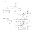
- Fig. 1 is a schematic view of a home power management network charged by being connected to an auxiliary power supply device according to an embodiment.
- Fig. 2 is a view illustrating an example of the auxiliary power supply device according to an embodiment.
- Fig. 3 is a view illustrating an internal constitution of the auxiliary power supply device according to an embodiment.
- Fig. 4 is a view illustrating an example of a home appliance connected to the auxiliary power supply device according to an embodiment.
- Fig. 6 is a view illustrating another example of a home appliance connected to the auxiliary power supply device according to an embodiment.
- Fig. 8 is a view illustrating another example of a home appliance connected to the auxiliary power supply device according to an embodiment.
- Fig. 10 is a flowchart illustrating a process of supplying power to the home appliance using the auxiliary power supply device according to an embodiment.
- the smart grid includes a plurality of power plants and a plurality of power generating facilities such as a solar cell station, a wind power plant, and a fuel cell station. Electricity generated by the power plants and power generating facilities are transmitted to a sub-control center.
- the sub-control center stores the electricity and transmits the electricity to a substation where the electricity is adjusted in voltage for being distributed to consumers such as residential customers and manufacturing plants.
- Fig. 1 illustrates an example of a power management network in a home that is one of consumers to which the electricity is distributed as described above.
- a home power management network 10 charged by being connected to an auxiliary power supply device includes an advanced metering infrastructure (AMI) 20 which is used to measure an amount of electricity and calculate electricity charges and an energy management system (EMS) connected to the AMI 20 for real-time power management and real-time power consumption prediction for consumers.
- AMI advanced metering infrastructure
- EMS energy management system
- the AMI 20 of the smart grid is backbone technology for integrating consumers based on an open architecture.
- the AMI 20 provides consumers with the ability to use electricity efficiently and power providers with the ability to detect problems on their systems and operate them efficiently.
- the AMI 20 provides a reference so that all electric devices can be connected to each other regardless of manufactures of the electric devices, and a real-time price signal of an electricity market is transmitted through the AMI 20 to the EMS 30 provided in a consumer.
- the EMS 30 includes the AMI 20 for real-time measurements of power, electricity rates, power consumption peak times and the EMS 30 capable of communicating with both the AMI 20 and the home appliances 1 to transmit and receive control signals for distributing electricity to the home appliances 1 to construct a power supply network 10. Also, the home appliances 1 may be connected to the power supply network 10 constructed as described above to receive operation power.
- the EMS 30 includes a display unit 31 for displaying current electricity consumption states and external environments (such as temperature and humidity), an input unit 32 that can be manipulated by a user, a communication unit (now shown) for communication with the home appliances 1 through radio waves or wires such as PLC, and the control unit (not shown) for processing control signals.
- a display unit 31 for displaying current electricity consumption states and external environments (such as temperature and humidity)
- an input unit 32 that can be manipulated by a user
- a communication unit (now shown) for communication with the home appliances 1 through radio waves or wires such as PLC
- the control unit not shown
- an auxiliary power supply device 200 is coupled to an outlet 50 connected to the power management network 10 including the AMI 20 and the EMS 30 to receive power for charging.
- the auxiliary power supply device 200 includes a connecting plug 300 communicating with the EMS 30.
- a coupling part 312 which is fitted into a socket 52 provided in the outlet 50 is disposed in the connecting plug 300.
- the electricity supplied from the connecting plug 300 is transmitted into an electricity input unit 230 provided in the auxiliary power supply device 200 and stored in a charging unit 260.
- the auxiliary power supply device 200 includes a power supply device communication unit 270 for transmitting/receiving a control signal into/from the home appliances 1 and a power supply device control unit 250 for controlling the charging and the supply of the charged power and processing the control signal.
- Fig. 4 is a view illustrating an example of a home appliance connected to the auxiliary power supply device according to an embodiment.
- Fig. 5 is a block diagram illustrating a control constitution of the home appliance and the auxiliary power supply device of Fig. 4 .
- a cooker 400 for cooking foods is provided.
- the cooker 400 includes a cooker body 410 having an approximately rectangular shape with a hollow therein to receive foods and a cooking chamber 420 for cooking the received foods by selectively using a plurality of heating sources.
- control panel 440 includes a manipulation unit 444 for selecting a heating source to be operated by a user's push manipulation or rotation manipulation and controlling a cooking time of the selected heating source and a cooker display 442 for displaying a control command inputted by the manipulation unit 444, a control state according to the control command, and operation information of the cooking chamber 420.
- a cooker auxiliary power connection unit 490 for using the charging power stored in the auxiliary power supply device 200 is disposed on a side of the cooker body 410.
- the cooker auxiliary power connection unit 490 and the auxiliary power supply device 200 may be connected to each other through a connection cable 90.
- a home appliance interface 240 connected to the cooker 400 through the connection cable 90 is disposed in the cooker auxiliary power connection unit 490
- a cooker interface 470 connected to the auxiliary power supply device 200 through the cooker auxiliary power connection unit 490 is disposed in the cooker 400 to supply the charged electricity and transmit the control signal.
- the electricity provided from the auxiliary power supply device 200 may be used by the cooker power management unit 460.
- the cooker power management unit 460 controls the electricity provided through the power supply network 10 to use the electricity as an operation power source for cooker 400.
- a humidifier 500 for adjusting humidity to provide a clean indoor environment to an indoor space is provided.
- the humidifier body 510 provides a space for mounting the water tank 520 on a rear portion thereof. When the water tank 520 is mounted, the humidifier 510 processes water received in the water tank 520 to generate wet vapor.
- an ultrasonic generator or a heating element is equipped in the humidifier body 510, and a blower unit for discharging the generated wet vapor may be further included in the humidifier body 510.
- a home appliance interface 240 connected to the humidifier 500 through the connection cable 90 is disposed in the humidifier auxiliary power connection unit 590, and a humidifier interface 586 connected to the auxiliary power supply device 200 through the humidifier auxiliary power connection unit 590 is disposed in the humidifier 500 to supply the charged electricity and transmit the control signal.
- auxiliary power supply device 200 and the humidifier 500 are connected to each other through the connection cable 90, electricity stored in the charging unit 260 of the auxiliary power supply device 200 is supplied into the humidifier 500 through the electricity output unit 290. Also, a humidifier power management unit 584 for operating the humidifier 500 using the supplied electricity is disposed in the humidifier 500.
- the electricity provided from the auxiliary power supply device 200 may be used by the humidifier power management unit 584.
- the humidifier power management unit 584 controls the electricity provided through the power supply network 10 to use the electricity as an operation power source for humidifier 500.
- the auxiliary power supply device display unit 220 of the auxiliary power supply device 200 may display consumption of the charged electricity and a charge of the electricity.
- Fig. 8 is a view illustrating another example of the home appliance connected to the auxiliary power supply device according to an embodiment.
- Fig. 9 is a block diagram illustrating a control constitution of the home appliance and the auxiliary power supply device of Fig. 8 .
- a massage chair 600 for massaging a user's body is provided.
- the massage chair 600 includes a massage chair body 610 having a chair shape to massage the user's body, a plurality of motors, and an air adjustment device connected to a plurality of air bags to selectively massage at least one portion of the user's body.
- the massage chair body 610 includes a back pad 614 for massaging a user's back, a headrest pad 612 for massaging the user's neck, a hip pad 616 for massaging the user's hip, an arm massage part 440, a leg massage part 640, and a foot massage part 630, which are operated independently.
- the motors or air adjustment device that are controlled independently are provided to separately massage each portion of the user's body.
- each of the back pad 614, the headrest pad 612, and the hip pad 616 includes a plurality of massage protrusions connected to the motors to massage corresponding portions of the user seated thereon while moving in various patterns.
- the arm massage part 640 and the leg massage part 760 use the air adjustment devices to expand and contract the air bags, thereby massaging the user's hands and legs.
- the massage chair 600 includes a remote controller 660 for separately or concurrently operating the massage parts configured above according to a user's need and a control unit 660 for transmitting a control command to each massage part according to contents selected by the remote controller 660.
- the remote controller 660 is disposed on a side of the arm massage part 640 so that the user seated on the massage chair 600 may conveniently check and operate the remote controller 660.
- the remote controller 660 includes a touch type display 662 so that the user may easily check and select an operation mode.
- the user may input a control signal and confirm a controlled state through the touch type display 662 in a state where the user is seated on the massage chair body 610.
- a massage chair auxiliary power connection unit 690 for using the charging power stored in the auxiliary power supply device 200 is disposed on a side of the massage chair body 610.
- the massage chair auxiliary power connection unit 690 and the auxiliary power supply device 200 may be connected to each other through a connection cable 90, like the humidifier 500.
- auxiliary power supply device 200 and the massage chair 600 are connected to each other through the connection cable 90, electricity stored in the charging unit 260 of the auxiliary power supply device 200 is supplied into the massage chair 600 through the electricity output unit 290. Also, a massage chair power management unit 684 for operating the massage chair 600 using the supplied electricity is disposed in the massage chair 600.
- the electricity provided from the auxiliary power supply device 200 may be used by the massage chair power management unit 684.
- the massage chair power management unit 684 controls the electricity provided through the power supply network 10 to use the electricity as an operation power source for massage chair 600.
- the auxiliary power supply device display unit 220 of the auxiliary power supply device 200 may display consumption of the charged electricity and a charge of the electricity.
- Fig. 10 is a flowchart illustrating a process of supplying power to the home appliance using the auxiliary power supply device according to an embodiment.
- the auxiliary power supply device 200 is connected to the power supply network 10 configured to receive electricity from the plurality of power sources, thereby distributing the electricity into the home appliances.
- the connecting plug 300 of the auxiliary power supply device 200 is fitted into the socket 52.
- the EMS 30 and the auxiliary power supply device 200 communicate with each other through the plug communication unit 360.
- the uppermost suppliable electricity charge may be an electricity charge supplied from an electric power company in a late night time.
- the auxiliary power supply device 200 is charged from the power supply source.
- the auxiliary power supply device 200 informs charge completion information into the EMS 30 through the plug communication unit 360.
- the EMS 30 receiving the charge completion information informs whether the charging of the auxiliary power supply device 200 is completed into only the home appliances 1 connected to the power management network 10.
- the home appliances 1 connected to the power management network 10 to operate may confirm the transmitted information and thus confirm that the auxiliary power supply device 200 is usable.
- the user may release the connection of the power plug connected to the power management network 10 and connect the auxiliary power supply device 200 so as to use the electricity having the relatively inexpensive electricity charge.
- the user connects the power plug to the power management network 10 before the connection of the auxiliary power supply device 200 is released.
- the connection of the auxiliary power supply device 200 is released in a state where the power supply is maintained.
- the auxiliary power supply device 200 of which the connection is released may be connected to the power management network 10 again and charged. When the charging is completed, the above-described processes may be repeated to provide relatively inexpensive electricity into the home appliances 1.
- electricity supplied into homes may be provided at a low price during the late night time at which the number of consumers is relatively less.
- electricity may be produced using solar energy, wind power, fuel cells, and the like, except for the power supplied from the electric power company.
- the produced electricity may be relatively inexpensive than that of the electricity provided from the electric power company.
- the user may use the relatively inexpensive electricity.
- the auxiliary power supply device may be connected to the home power management network including the EMS, and thus charged at a relatively inexpensive price.
- the charge completion state may be informed to the communicable home appliances through the power management network.
- the user which confirmed the charge completion information of the auxiliary power supply device transmitted into the home appliances may connect the auxiliary power supply device to the home appliances to utilize the electricity at a relatively inexpensive price.
- auxiliary power supply device when used, power losses may be reduced to develop related industries and reduce environmental pollution occurring when electricity is produced.
Applications Claiming Priority (1)
| Application Number | Priority Date | Filing Date | Title |
|---|---|---|---|
| PCT/KR2010/000230 WO2011087165A1 (ko) | 2010-01-14 | 2010-01-14 | 지능형 전력망을 이용하는 가전제품의 보조전원공급장치 |
Publications (3)
| Publication Number | Publication Date |
|---|---|
| EP2525471A1 true EP2525471A1 (de) | 2012-11-21 |
| EP2525471A4 EP2525471A4 (de) | 2013-12-25 |
| EP2525471B1 EP2525471B1 (de) | 2015-04-29 |
Family
ID=44304423
Family Applications (1)
| Application Number | Title | Priority Date | Filing Date |
|---|---|---|---|
| EP20100843231 Not-in-force EP2525471B1 (de) | 2010-01-14 | 2010-01-14 | Notstromversorgungsvorrichtung für haushaltsgeräte mit intelligentem stromnetz |
Country Status (4)
| Country | Link |
|---|---|
| US (1) | US20120310425A1 (de) |
| EP (1) | EP2525471B1 (de) |
| RU (1) | RU2510557C1 (de) |
| WO (1) | WO2011087165A1 (de) |
Families Citing this family (12)
| Publication number | Priority date | Publication date | Assignee | Title |
|---|---|---|---|---|
| DE102010040296A1 (de) * | 2010-09-06 | 2012-03-08 | BSH Bosch und Siemens Hausgeräte GmbH | Verfahren für den Wechsel zu einem günstigeren Verbrauchstarif für ein Hausgerät sowie dafür geeignetes Hausgerät |
| US8761050B2 (en) | 2011-10-04 | 2014-06-24 | Advanergy, Inc. | Network integration system and method |
| KR101530314B1 (ko) * | 2011-12-16 | 2015-06-23 | 주식회사 케이티 | 수요반응 시스템 및 방법 |
| US10116747B2 (en) * | 2013-02-05 | 2018-10-30 | Txu Energy Retail Company Llc | Electricity provider content platform |
| EP3497768B8 (de) * | 2016-08-08 | 2023-12-06 | Orison Inc. | Plug-and-play mit intelligenten energiespeichereinheiten |
| USD891422S1 (en) | 2018-12-04 | 2020-07-28 | Innovative Strollers Llc | Single-sided kiosk system |
| USD891421S1 (en) | 2018-12-04 | 2020-07-28 | Innovative Strollers Llc | Double-sided kiosk system |
| WO2020150028A1 (en) | 2019-01-18 | 2020-07-23 | Innovative Strollers, LLC | Vending system with smart lock mechanisms |
| USD914667S1 (en) | 2020-01-08 | 2021-03-30 | Innovative Vending Solutions, Llc | Display device |
| USD1018097S1 (en) | 2020-01-31 | 2024-03-19 | Innovative Vending Solutions, Llc | Massage chairs with display device |
| USD1002217S1 (en) | 2020-09-14 | 2023-10-24 | Innovative Vending Solutions Llc | Massage chairs with a display device and a partition |
| USD979270S1 (en) | 2020-09-14 | 2023-02-28 | Innovative Vending Solutions Llc | Massage chair with kiosk display and partition |
Citations (8)
| Publication number | Priority date | Publication date | Assignee | Title |
|---|---|---|---|---|
| WO2002017151A1 (en) * | 2000-08-21 | 2002-02-28 | Anil Lasantha Michael Perera | Method to enable customers to respond to prices in a pool type energy market |
| WO2003084022A1 (en) * | 2002-03-28 | 2003-10-09 | Robertshaw Controls Company | Energy management system and method |
| CA2469768A1 (en) * | 2004-06-22 | 2005-12-22 | Brian R. Parisien | A methodology for time-shifting electrical grid energy consumption to optimize cost rate and grid load level |
| US20060276938A1 (en) * | 2005-06-06 | 2006-12-07 | Equinox Energy Solutions, Inc. | Optimized energy management system |
| US20090048716A1 (en) * | 2004-06-15 | 2009-02-19 | John Joseph Marhoefer | Method and Apparatus for Optimization of Distributed Generation |
| US20090127932A1 (en) * | 2007-11-21 | 2009-05-21 | Donald Warren | Intelligent auxiliary power supply system with current and temperature monitoring capabilities |
| US20090292402A1 (en) * | 2008-04-14 | 2009-11-26 | Cruickshank Iii Robert F | Method & apparatus for orchestrating utility power supply & demand in real time using a continuous pricing signal sent via a network to home networks & smart appliances |
| WO2009146287A1 (en) * | 2008-05-30 | 2009-12-03 | Chun-Chieh Chang | Multipurpose portable storage and supply system |
Family Cites Families (10)
| Publication number | Priority date | Publication date | Assignee | Title |
|---|---|---|---|---|
| KR100186435B1 (ko) * | 1996-12-31 | 1999-05-15 | 구자홍 | 가정용 전력 제어기 |
| KR20000010188A (ko) * | 1998-07-30 | 2000-02-15 | 김준철 | 전원공급 시스템의 절전 제어장치와 그 방법 |
| JP2003172578A (ja) * | 2001-12-07 | 2003-06-20 | Hitachi Ltd | ネットワーク対応家電機器、家電機器点検システム及び家電機器点検サービス |
| EP1367685A1 (de) * | 2002-05-31 | 2003-12-03 | Whirlpool Corporation | Elektronisches System zur Geräteleistungsverbrauchsverwaltung |
| KR100613577B1 (ko) * | 2004-11-11 | 2006-08-16 | 주식회사 대우일렉트로닉스 | 홈 네트워크 시스템의 전력 제어장치 |
| US8615332B2 (en) * | 2005-06-09 | 2013-12-24 | Whirlpool Corporation | Smart current attenuator for energy conservation in appliances |
| WO2008073453A1 (en) * | 2006-12-11 | 2008-06-19 | V2Green, Inc. | Power aggregation system for distributed electric resources |
| JP4807329B2 (ja) * | 2007-06-14 | 2011-11-02 | トヨタ自動車株式会社 | ハイブリッド車両およびハイブリッド車両運用システム |
| US8872379B2 (en) * | 2007-11-30 | 2014-10-28 | Johnson Controls Technology Company | Efficient usage, storage, and sharing of energy in buildings, vehicles, and equipment |
| US8255090B2 (en) * | 2008-02-01 | 2012-08-28 | Energyhub | System and method for home energy monitor and control |
-
2010
- 2010-01-14 EP EP20100843231 patent/EP2525471B1/de not_active Not-in-force
- 2010-01-14 US US13/522,210 patent/US20120310425A1/en not_active Abandoned
- 2010-01-14 RU RU2012131516/07A patent/RU2510557C1/ru not_active IP Right Cessation
- 2010-01-14 WO PCT/KR2010/000230 patent/WO2011087165A1/ko active Application Filing
Patent Citations (8)
| Publication number | Priority date | Publication date | Assignee | Title |
|---|---|---|---|---|
| WO2002017151A1 (en) * | 2000-08-21 | 2002-02-28 | Anil Lasantha Michael Perera | Method to enable customers to respond to prices in a pool type energy market |
| WO2003084022A1 (en) * | 2002-03-28 | 2003-10-09 | Robertshaw Controls Company | Energy management system and method |
| US20090048716A1 (en) * | 2004-06-15 | 2009-02-19 | John Joseph Marhoefer | Method and Apparatus for Optimization of Distributed Generation |
| CA2469768A1 (en) * | 2004-06-22 | 2005-12-22 | Brian R. Parisien | A methodology for time-shifting electrical grid energy consumption to optimize cost rate and grid load level |
| US20060276938A1 (en) * | 2005-06-06 | 2006-12-07 | Equinox Energy Solutions, Inc. | Optimized energy management system |
| US20090127932A1 (en) * | 2007-11-21 | 2009-05-21 | Donald Warren | Intelligent auxiliary power supply system with current and temperature monitoring capabilities |
| US20090292402A1 (en) * | 2008-04-14 | 2009-11-26 | Cruickshank Iii Robert F | Method & apparatus for orchestrating utility power supply & demand in real time using a continuous pricing signal sent via a network to home networks & smart appliances |
| WO2009146287A1 (en) * | 2008-05-30 | 2009-12-03 | Chun-Chieh Chang | Multipurpose portable storage and supply system |
Non-Patent Citations (1)
| Title |
|---|
| See also references of WO2011087165A1 * |
Also Published As
| Publication number | Publication date |
|---|---|
| WO2011087165A1 (ko) | 2011-07-21 |
| EP2525471A4 (de) | 2013-12-25 |
| RU2510557C1 (ru) | 2014-03-27 |
| RU2012131516A (ru) | 2014-02-20 |
| EP2525471B1 (de) | 2015-04-29 |
| US20120310425A1 (en) | 2012-12-06 |
Similar Documents
| Publication | Publication Date | Title |
|---|---|---|
| EP2525471B1 (de) | Notstromversorgungsvorrichtung für haushaltsgeräte mit intelligentem stromnetz | |
| EP2525307B1 (de) | Kundendienstsystem für hausgeräte mit intelligentem stromnetz | |
| US9337658B2 (en) | Network system | |
| US8798834B2 (en) | Movable component for a network system | |
| US20120203391A1 (en) | Network system and method of controlling the same | |
| WO2013057516A9 (en) | Smart meter apparatus | |
| KR101537620B1 (ko) | 전력공급네트워크 시스템 및 그 제어방법 | |
| KR20110042866A (ko) | 전력공급네트워크 시스템 및 그 제어방법 | |
| KR101069058B1 (ko) | 지능형 전력망을 이용하는 정수기 | |
| KR101101657B1 (ko) | 지능형 전력망을 이용하는 가전제품의 보조전원공급장치 | |
| KR101678439B1 (ko) | 이동식 전력공급장치 | |
| KR101166624B1 (ko) | 지능형 전력망을 이용하는 가전제품 | |
| KR101897816B1 (ko) | 네트워크 시스템 | |
| WO2011103283A1 (en) | A movable component for a network system | |
| KR101687026B1 (ko) | 네트워크 시스템 | |
| KR101611623B1 (ko) | 네트워크 시스템 | |
| KR101820163B1 (ko) | 네트워크 시스템 | |
| KR101821815B1 (ko) | 네트워크 시스템 | |
| KR101897819B1 (ko) | 네트워크 시스템 및 그 제어방법 | |
| KR101605209B1 (ko) | 네트워크 시스템 | |
| KR101605910B1 (ko) | 네트워크 시스템 | |
| KR20120029568A (ko) | 네트워크 시스템 | |
| KR20120005666A (ko) | 통신컴포넌트의 제어방법 | |
| KR20110042863A (ko) | 전력공급네트워크 시스템 및 그 제어방법 | |
| KR20110042867A (ko) | 전력공급네트워크 시스템 및 그 제어방법 |
Legal Events
| Date | Code | Title | Description |
|---|---|---|---|
| PUAI | Public reference made under article 153(3) epc to a published international application that has entered the european phase |
Free format text: ORIGINAL CODE: 0009012 |
|
| 17P | Request for examination filed |
Effective date: 20120801 |
|
| AK | Designated contracting states |
Kind code of ref document: A1 Designated state(s): AT BE BG CH CY CZ DE DK EE ES FI FR GB GR HR HU IE IS IT LI LT LU LV MC MK MT NL NO PL PT RO SE SI SK SM TR |
|
| DAX | Request for extension of the european patent (deleted) | ||
| A4 | Supplementary search report drawn up and despatched |
Effective date: 20131121 |
|
| RIC1 | Information provided on ipc code assigned before grant |
Ipc: H02J 13/00 20060101AFI20131115BHEP Ipc: H02J 3/14 20060101ALI20131115BHEP |
|
| GRAP | Despatch of communication of intention to grant a patent |
Free format text: ORIGINAL CODE: EPIDOSNIGR1 |
|
| INTG | Intention to grant announced |
Effective date: 20140812 |
|
| GRAS | Grant fee paid |
Free format text: ORIGINAL CODE: EPIDOSNIGR3 |
|
| GRAP | Despatch of communication of intention to grant a patent |
Free format text: ORIGINAL CODE: EPIDOSNIGR1 |
|
| GRAA | (expected) grant |
Free format text: ORIGINAL CODE: 0009210 |
|
| INTG | Intention to grant announced |
Effective date: 20150311 |
|
| AK | Designated contracting states |
Kind code of ref document: B1 Designated state(s): AT BE BG CH CY CZ DE DK EE ES FI FR GB GR HR HU IE IS IT LI LT LU LV MC MK MT NL NO PL PT RO SE SI SK SM TR |
|
| REG | Reference to a national code |
Ref country code: GB Ref legal event code: FG4D |
|
| REG | Reference to a national code |
Ref country code: CH Ref legal event code: EP |
|
| REG | Reference to a national code |
Ref country code: AT Ref legal event code: REF Ref document number: 724913 Country of ref document: AT Kind code of ref document: T Effective date: 20150515 |
|
| REG | Reference to a national code |
Ref country code: IE Ref legal event code: FG4D |
|
| REG | Reference to a national code |
Ref country code: DE Ref legal event code: R096 Ref document number: 602010024388 Country of ref document: DE Effective date: 20150611 |
|
| REG | Reference to a national code |
Ref country code: NL Ref legal event code: VDEP Effective date: 20150429 |
|
| REG | Reference to a national code |
Ref country code: AT Ref legal event code: MK05 Ref document number: 724913 Country of ref document: AT Kind code of ref document: T Effective date: 20150429 |
|
| REG | Reference to a national code |
Ref country code: LT Ref legal event code: MG4D |
|
| PG25 | Lapsed in a contracting state [announced via postgrant information from national office to epo] |
Ref country code: NL Free format text: LAPSE BECAUSE OF FAILURE TO SUBMIT A TRANSLATION OF THE DESCRIPTION OR TO PAY THE FEE WITHIN THE PRESCRIBED TIME-LIMIT Effective date: 20150429 |
|
| PG25 | Lapsed in a contracting state [announced via postgrant information from national office to epo] |
Ref country code: LT Free format text: LAPSE BECAUSE OF FAILURE TO SUBMIT A TRANSLATION OF THE DESCRIPTION OR TO PAY THE FEE WITHIN THE PRESCRIBED TIME-LIMIT Effective date: 20150429 Ref country code: ES Free format text: LAPSE BECAUSE OF FAILURE TO SUBMIT A TRANSLATION OF THE DESCRIPTION OR TO PAY THE FEE WITHIN THE PRESCRIBED TIME-LIMIT Effective date: 20150429 Ref country code: FI Free format text: LAPSE BECAUSE OF FAILURE TO SUBMIT A TRANSLATION OF THE DESCRIPTION OR TO PAY THE FEE WITHIN THE PRESCRIBED TIME-LIMIT Effective date: 20150429 Ref country code: PT Free format text: LAPSE BECAUSE OF FAILURE TO SUBMIT A TRANSLATION OF THE DESCRIPTION OR TO PAY THE FEE WITHIN THE PRESCRIBED TIME-LIMIT Effective date: 20150831 Ref country code: NO Free format text: LAPSE BECAUSE OF FAILURE TO SUBMIT A TRANSLATION OF THE DESCRIPTION OR TO PAY THE FEE WITHIN THE PRESCRIBED TIME-LIMIT Effective date: 20150729 Ref country code: HR Free format text: LAPSE BECAUSE OF FAILURE TO SUBMIT A TRANSLATION OF THE DESCRIPTION OR TO PAY THE FEE WITHIN THE PRESCRIBED TIME-LIMIT Effective date: 20150429 |
|
| PG25 | Lapsed in a contracting state [announced via postgrant information from national office to epo] |
Ref country code: AT Free format text: LAPSE BECAUSE OF FAILURE TO SUBMIT A TRANSLATION OF THE DESCRIPTION OR TO PAY THE FEE WITHIN THE PRESCRIBED TIME-LIMIT Effective date: 20150429 Ref country code: IS Free format text: LAPSE BECAUSE OF FAILURE TO SUBMIT A TRANSLATION OF THE DESCRIPTION OR TO PAY THE FEE WITHIN THE PRESCRIBED TIME-LIMIT Effective date: 20150829 Ref country code: LV Free format text: LAPSE BECAUSE OF FAILURE TO SUBMIT A TRANSLATION OF THE DESCRIPTION OR TO PAY THE FEE WITHIN THE PRESCRIBED TIME-LIMIT Effective date: 20150429 Ref country code: GR Free format text: LAPSE BECAUSE OF FAILURE TO SUBMIT A TRANSLATION OF THE DESCRIPTION OR TO PAY THE FEE WITHIN THE PRESCRIBED TIME-LIMIT Effective date: 20150730 |
|
| REG | Reference to a national code |
Ref country code: FR Ref legal event code: PLFP Year of fee payment: 7 |
|
| PG25 | Lapsed in a contracting state [announced via postgrant information from national office to epo] |
Ref country code: DK Free format text: LAPSE BECAUSE OF FAILURE TO SUBMIT A TRANSLATION OF THE DESCRIPTION OR TO PAY THE FEE WITHIN THE PRESCRIBED TIME-LIMIT Effective date: 20150429 Ref country code: EE Free format text: LAPSE BECAUSE OF FAILURE TO SUBMIT A TRANSLATION OF THE DESCRIPTION OR TO PAY THE FEE WITHIN THE PRESCRIBED TIME-LIMIT Effective date: 20150429 |
|
| REG | Reference to a national code |
Ref country code: DE Ref legal event code: R097 Ref document number: 602010024388 Country of ref document: DE |
|
| PG25 | Lapsed in a contracting state [announced via postgrant information from national office to epo] |
Ref country code: RO Free format text: LAPSE BECAUSE OF NON-PAYMENT OF DUE FEES Effective date: 20150429 Ref country code: CZ Free format text: LAPSE BECAUSE OF FAILURE TO SUBMIT A TRANSLATION OF THE DESCRIPTION OR TO PAY THE FEE WITHIN THE PRESCRIBED TIME-LIMIT Effective date: 20150429 Ref country code: SK Free format text: LAPSE BECAUSE OF FAILURE TO SUBMIT A TRANSLATION OF THE DESCRIPTION OR TO PAY THE FEE WITHIN THE PRESCRIBED TIME-LIMIT Effective date: 20150429 Ref country code: PL Free format text: LAPSE BECAUSE OF FAILURE TO SUBMIT A TRANSLATION OF THE DESCRIPTION OR TO PAY THE FEE WITHIN THE PRESCRIBED TIME-LIMIT Effective date: 20150429 |
|
| PLBE | No opposition filed within time limit |
Free format text: ORIGINAL CODE: 0009261 |
|
| STAA | Information on the status of an ep patent application or granted ep patent |
Free format text: STATUS: NO OPPOSITION FILED WITHIN TIME LIMIT |
|
| 26N | No opposition filed |
Effective date: 20160201 |
|
| PG25 | Lapsed in a contracting state [announced via postgrant information from national office to epo] |
Ref country code: SI Free format text: LAPSE BECAUSE OF FAILURE TO SUBMIT A TRANSLATION OF THE DESCRIPTION OR TO PAY THE FEE WITHIN THE PRESCRIBED TIME-LIMIT Effective date: 20150429 Ref country code: BE Free format text: LAPSE BECAUSE OF NON-PAYMENT OF DUE FEES Effective date: 20160131 |
|
| PG25 | Lapsed in a contracting state [announced via postgrant information from national office to epo] |
Ref country code: LU Free format text: LAPSE BECAUSE OF FAILURE TO SUBMIT A TRANSLATION OF THE DESCRIPTION OR TO PAY THE FEE WITHIN THE PRESCRIBED TIME-LIMIT Effective date: 20160114 Ref country code: BE Free format text: LAPSE BECAUSE OF FAILURE TO SUBMIT A TRANSLATION OF THE DESCRIPTION OR TO PAY THE FEE WITHIN THE PRESCRIBED TIME-LIMIT Effective date: 20150429 |
|
| REG | Reference to a national code |
Ref country code: CH Ref legal event code: PL |
|
| PG25 | Lapsed in a contracting state [announced via postgrant information from national office to epo] |
Ref country code: MC Free format text: LAPSE BECAUSE OF FAILURE TO SUBMIT A TRANSLATION OF THE DESCRIPTION OR TO PAY THE FEE WITHIN THE PRESCRIBED TIME-LIMIT Effective date: 20150429 |
|
| PG25 | Lapsed in a contracting state [announced via postgrant information from national office to epo] |
Ref country code: LI Free format text: LAPSE BECAUSE OF NON-PAYMENT OF DUE FEES Effective date: 20160131 Ref country code: CH Free format text: LAPSE BECAUSE OF NON-PAYMENT OF DUE FEES Effective date: 20160131 |
|
| REG | Reference to a national code |
Ref country code: IE Ref legal event code: MM4A |
|
| REG | Reference to a national code |
Ref country code: FR Ref legal event code: PLFP Year of fee payment: 8 |
|
| PG25 | Lapsed in a contracting state [announced via postgrant information from national office to epo] |
Ref country code: IE Free format text: LAPSE BECAUSE OF NON-PAYMENT OF DUE FEES Effective date: 20160114 |
|
| PG25 | Lapsed in a contracting state [announced via postgrant information from national office to epo] |
Ref country code: SE Free format text: LAPSE BECAUSE OF FAILURE TO SUBMIT A TRANSLATION OF THE DESCRIPTION OR TO PAY THE FEE WITHIN THE PRESCRIBED TIME-LIMIT Effective date: 20150429 |
|
| PG25 | Lapsed in a contracting state [announced via postgrant information from national office to epo] |
Ref country code: MT Free format text: LAPSE BECAUSE OF FAILURE TO SUBMIT A TRANSLATION OF THE DESCRIPTION OR TO PAY THE FEE WITHIN THE PRESCRIBED TIME-LIMIT Effective date: 20150429 |
|
| REG | Reference to a national code |
Ref country code: FR Ref legal event code: PLFP Year of fee payment: 9 |
|
| PG25 | Lapsed in a contracting state [announced via postgrant information from national office to epo] |
Ref country code: CY Free format text: LAPSE BECAUSE OF FAILURE TO SUBMIT A TRANSLATION OF THE DESCRIPTION OR TO PAY THE FEE WITHIN THE PRESCRIBED TIME-LIMIT Effective date: 20150429 Ref country code: SM Free format text: LAPSE BECAUSE OF FAILURE TO SUBMIT A TRANSLATION OF THE DESCRIPTION OR TO PAY THE FEE WITHIN THE PRESCRIBED TIME-LIMIT Effective date: 20150429 Ref country code: HU Free format text: LAPSE BECAUSE OF FAILURE TO SUBMIT A TRANSLATION OF THE DESCRIPTION OR TO PAY THE FEE WITHIN THE PRESCRIBED TIME-LIMIT; INVALID AB INITIO Effective date: 20100114 |
|
| PG25 | Lapsed in a contracting state [announced via postgrant information from national office to epo] |
Ref country code: MT Free format text: LAPSE BECAUSE OF FAILURE TO SUBMIT A TRANSLATION OF THE DESCRIPTION OR TO PAY THE FEE WITHIN THE PRESCRIBED TIME-LIMIT Effective date: 20160131 Ref country code: MK Free format text: LAPSE BECAUSE OF FAILURE TO SUBMIT A TRANSLATION OF THE DESCRIPTION OR TO PAY THE FEE WITHIN THE PRESCRIBED TIME-LIMIT Effective date: 20150429 Ref country code: TR Free format text: LAPSE BECAUSE OF FAILURE TO SUBMIT A TRANSLATION OF THE DESCRIPTION OR TO PAY THE FEE WITHIN THE PRESCRIBED TIME-LIMIT Effective date: 20150429 |
|
| PG25 | Lapsed in a contracting state [announced via postgrant information from national office to epo] |
Ref country code: BG Free format text: LAPSE BECAUSE OF FAILURE TO SUBMIT A TRANSLATION OF THE DESCRIPTION OR TO PAY THE FEE WITHIN THE PRESCRIBED TIME-LIMIT Effective date: 20150429 |
|
| PGFP | Annual fee paid to national office [announced via postgrant information from national office to epo] |
Ref country code: FR Payment date: 20191209 Year of fee payment: 11 |
|
| PGFP | Annual fee paid to national office [announced via postgrant information from national office to epo] |
Ref country code: GB Payment date: 20191209 Year of fee payment: 11 Ref country code: IT Payment date: 20200114 Year of fee payment: 11 |
|
| PGFP | Annual fee paid to national office [announced via postgrant information from national office to epo] |
Ref country code: DE Payment date: 20201207 Year of fee payment: 12 |
|
| GBPC | Gb: european patent ceased through non-payment of renewal fee |
Effective date: 20210114 |
|
| PG25 | Lapsed in a contracting state [announced via postgrant information from national office to epo] |
Ref country code: FR Free format text: LAPSE BECAUSE OF NON-PAYMENT OF DUE FEES Effective date: 20210131 |
|
| PG25 | Lapsed in a contracting state [announced via postgrant information from national office to epo] |
Ref country code: GB Free format text: LAPSE BECAUSE OF NON-PAYMENT OF DUE FEES Effective date: 20210114 |
|
| PG25 | Lapsed in a contracting state [announced via postgrant information from national office to epo] |
Ref country code: IT Free format text: LAPSE BECAUSE OF NON-PAYMENT OF DUE FEES Effective date: 20210114 |
|
| REG | Reference to a national code |
Ref country code: DE Ref legal event code: R119 Ref document number: 602010024388 Country of ref document: DE |
|
| PG25 | Lapsed in a contracting state [announced via postgrant information from national office to epo] |
Ref country code: DE Free format text: LAPSE BECAUSE OF NON-PAYMENT OF DUE FEES Effective date: 20220802 |