EP2525382B1 - Combined function circuit protection and control device actuator - Google Patents
Combined function circuit protection and control device actuator Download PDFInfo
- Publication number
- EP2525382B1 EP2525382B1 EP11004034.2A EP11004034A EP2525382B1 EP 2525382 B1 EP2525382 B1 EP 2525382B1 EP 11004034 A EP11004034 A EP 11004034A EP 2525382 B1 EP2525382 B1 EP 2525382B1
- Authority
- EP
- European Patent Office
- Prior art keywords
- control device
- circuit protection
- plunger
- actuator
- magnetic
- Prior art date
- Legal status (The legal status is an assumption and is not a legal conclusion. Google has not performed a legal analysis and makes no representation as to the accuracy of the status listed.)
- Not-in-force
Links
Images

Classifications
-
- H—ELECTRICITY
- H01—ELECTRIC ELEMENTS
- H01H—ELECTRIC SWITCHES; RELAYS; SELECTORS; EMERGENCY PROTECTIVE DEVICES
- H01H51/00—Electromagnetic relays
-
- H—ELECTRICITY
- H01—ELECTRIC ELEMENTS
- H01H—ELECTRIC SWITCHES; RELAYS; SELECTORS; EMERGENCY PROTECTIVE DEVICES
- H01H71/00—Details of the protective switches or relays covered by groups H01H73/00 - H01H83/00
- H01H71/10—Operating or release mechanisms
- H01H71/12—Automatic release mechanisms with or without manual release
- H01H71/24—Electromagnetic mechanisms
Definitions
- An actuator is typically used in electrical protection devices as a means to break a circuit after a fault condition has been detected.
- an actuator used in electrical protection devices are typically a relay or a solenoid both having some form of plunger or lever which travels a set distance to interface with a mechanism that determines the contact state.
- Circuit protection and control device current rating and short circuit fault breaking capacity are key functions that contribute to the size of a circuit protection and control device in terms of primary current path conductor size in relation to the maximum current rating of the circuit protection and control device and the size of the arc extinguishing components in relation to the short circuit breaking capacity.
- Circuit protection and control device over current fault protection functionality is typically provided by a bimetal which due to its size and actuating action requires a significant portion of the available space within a circuit protection and control device.
- This problem is added to further by specific generic types of circuit protection and control device technology, namely voltage dependant and voltage independent type circuit protection and control device technology.
- the differential current sensor in a voltage independent circuit protection and control device is significantly larger than is typical in a voltage dependant circuit protection and control device due mainly to the need for the current induced in the secondary winding from the differential fault current to be sufficient to power the actuator to trip the circuit protection and control device mechanism and open the primary conductor path contacts.
- a magnetic latch relay is the typical actuation method used in a voltage independent circuit protection and control device due to the minimal amount of current required to change the relay state.
- the size and manufactured cost of these relays are typically larger and higher than a solenoid used in a voltage dependant circuit protection and control device.
- This invention overcomes and resolves these problems by combining tripping functionality typically taking up a large amount of available space within a circuit protection and control device into the space taken by a single actuator.
- This invention combines two independent actuators in the physical space typically taken up by a solenoid assembly used in a circuit protection and control device to provide actuation in the case of a short circuit or gross over current fault condition.
- This invention describes an actuation means combining two independent actuators occupying the three dimensional space used by a single actuator characterized by a primary actuator and a secondary actuator whereby the secondary actuator is the plunger of the primary actuator said secondary actuator construction is further characterized by a combined function housing in which the secondary actuator components are located said combined function housing acting to isolate the magnetic field generated by the windings of the primary actuator from the magnetic components of said secondary actuator.
- This invention further describes the said actuation means used to open & close a circuit protection device characterized by at least a pair of separable contacts in the line or plurality of conductor paths used for controlling the current supplied to a load circuit, the contacts being operated by a mechanism which uses an actuator as its stimulus to open & close said contacts the actuator having two independent means of tripping said circuit protection device and constructed in a manner where both tripping means occupy the three dimensional physical space used for a single tripping means the actuator is characterized as having a primary and secondary actuator.
- the primary actuator can be used as a means to trip a mechanism as a result of a short circuit condition.
- the primary actuator is a solenoid characterized by a primary winding, molding, frame and spring, the plunger which is driven against the force of a spring during a gross over current fault condition to move the plunger towards the centre of the solenoid windings.
- the plunger engages with the circuit protection and control device mechanism to open the main circuit protection and control device contacts.
- the combination of the spring and magnitude of the over current determine the rate at which the device opens the circuit protection and control device contacts and thus complying with the requirement of the relevant circuit protection and control device standards.
- the secondary actuator is the primary actuator plunger.
- the primary actuator plunger comprises a combined function housing for the secondary actuator which isolates the magnetic circuit within the secondary actuator from the magnetic field developed by the primary actuator and a winding to generate a magnetic field within the secondary actuator.
- the combined function housing is characterized by a magnetic external housing, a non magnetic region which magnetically isolates the secondary actuator magnetic circuit however the combined function housing may also be characterized by a magnetic external housing, non magnetic region which magnetically isolates the secondary actuator.
- the secondary actuator is characterized by a secondary actuator plunger comprising of a magnetic portion and a non magnetic portion the magnetic portion is contained within the magnetic circuit component & is contained within the combined function housing non magnetic region.
- the non magnetic portion of the plunger is a combined interface function for the primary & secondary actuator
- the secondary actuator can be a solenoid, magnetic latch solenoid or mechanical latch solenoid.
- the secondary actuator comprises of a bobbin and either a winding or plurality of windings. The terminations for the secondary actuator windings pass through the combined function housing.
- An embodiment of this invention has as the secondary actuator a magnetic latch solenoid comprises a combined function housing, spring, magnetic plunger, non magnetic plunger, permanent magnet, plunger plate, bobbin and winding which utilises a permanent magnet in circuit with a plunger plate, a secondary plunger in which the magnetic portion is held by a permanent magnet and the inner portion of the primary actuator plunger and housing.
- a secondary actuator can be used as a means to trip a mechanism as a result of a over current fault condition, earth leakage fault condition, arc fault condition, under voltage fault condition, over voltage fault condition, loss of neutral fault condition, as a result of an internal component failure condition which renders the device unsafe, a result of a command from an external or remote location, an energy usage limit, a signal embedded in the line voltage and as a result of a DC residual current fault condition.
- This embodiment of a secondary actuator has a coil wound around a bobbin which the secondary plunger passes through and when the coil has a small amount of pulsed current applied will act on the magnetic circuit sufficiently to weaken the magnetic holding force of the permanent magnet on the secondary plunger sufficient to allow the force of a secondary actuating spring to pull the secondary plunger away from the plunger plate and the non magnetic portion of the secondary plunger to engage with the circuit protection and control device mechanism to trip or open the main circuit protection and control device contacts.
- the secondary actuator is reset by the action of the circuit protection and control device mechanism when the circuit protection and control device main contacts are closed thus forcing the secondary plunger to engage with the plunger plate and the holding force of the permanent magnet and compressing the secondary actuating spring.
- This embodiment of a combination of two independent actuators in the same space typically used by a circuit protection and control device which uses a solenoid assembly to provide actuation in the case of a short circuit or gross over current fault condition can be used in either a voltage independent or voltage dependant circuit protection and control device for tripping or opening the main circuit protection and control device contacts in response to a plurality of fault conditions or functional requirements.
- a further embodiment of this invention has as the secondary actuator a mechanical latch solenoid comprises a combined function housing, spring, magnetic plunger, non magnetic plunger, mechanical latch, bobbin and winding
- This embodiment of a secondary actuator has a coil wound around a bobbin which the secondary plunger passes through and when the coil has a small amount of pulsed current applied will act on the secondary plunger sufficiently to weaken the mechanical latch holding force on the secondary plunger sufficient to allow the force of a secondary actuating spring to pull the secondary plunger away from the mechanical latch and the non magnetic portion of the secondary plunger to engage with the circuit protection and control device mechanism to trip or open the main circuit protection and control device contacts.
- the secondary actuator is reset by the action of the circuit protection and control device mechanism when the circuit protection and control device main contacts are closed thus forcing the secondary plunger to engage with the mechanical latch and compress the secondary actuating spring.
- This embodiment of a combination of two independent actuators in the same space typically used by a circuit protection and control device which uses a solenoid assembly to provide actuation in the case of a short circuit or gross over current fault condition can be used in either a voltage independent or voltage dependant circuit protection and control device for tripping or opening the main circuit protection and control device contacts in response to a plurality of fault conditions or functional requirements.
- a further embodiment of this invention has as the secondary actuator a solenoid comprises a combined function housing, pole piece, firming ring, magnetic plunger, non magnetic plunger, bobbin and winding.
- This embodiment of a secondary actuator has a pole piece, a firming ring, a secondary plunger which the non magnetic portion is located within the secondary actuator magnetic portion and is held in position by an opposing spring, a winding around a bobbin all of which the secondary plunger passes through and when sufficient current is applied to the winding will pull the secondary plunger magnetic portion against the force of the primary actuator spring to move to engage with the pole piece, the firming ring preventing buzzing when AC current is applied and thus the non magnetic portion of the secondary plunger to engage with the circuit protection and control device mechanism to trip or open the main circuit protection and control device contacts.
- the secondary actuator is reset when the current to the secondary winding is removed and the primary actuator spring returns the secondary plunger back to its rest position.
- This embodiment is suitable for a voltage dependant circuit protection and control device due to the increased amount of current required in the secondary actuator windings to move the secondary plunger.
- a further embodiment of this invention has as a secondary actuator a solenoid comprises a combined function housing, magnetic plunger, non magnetic plunger, bobbin and winding.
- This secondary actuator is located within the primary actuator plunger and when sufficient current is applied to the winding will pull the secondary plunger which the non magnetic portion is located within the secondary actuator magnetic portion and is held in position by an opposing spring, to the centre of the windings against the force of the primary actuator spring and the non magnetic portion of the secondary plunger to engage with the circuit protection and control device mechanism to trip or open the circuit protection and control device main contacts.
- the secondary actuator is reset when the current to the secondary winding is removed and the primary actuator spring returns the secondary plunger back to its rest position.
- the primary actuator plunger also acts as a housing having the means to isolate the secondary plunger from the effects of the magnetic field generated from the winding of the primary actuator in an over current or gross over current fault condition.
- This embodiment can be used in a voltage dependant circuit protection and control device due to the increased amount of current required in the secondary actuator windings to move the secondary plunger.
- the primary or secondary actuators can be physically configured to operate in opposite axial directions or in the same axial direction thus enabling a suitable mechanism to open the main contacts of a circuit protection and control device with either the primary or secondary actuator and subsequently using either the primary or secondary actuator to act upon the mechanism to close the main contacts of a circuit protection and control device dependant on sufficient energy being available to the actuator when the main contacts are open.
- a further embodiment of this invention has the combined primary and secondary actuation utilised in a circuit protection and control device to open and close at least a pair of separable contacts in the line or plurality of conductor paths used for controlling the current supplied to a load circuit, the contacts being operated by a mechanism which uses an actuator as its stimulus to open and close said contacts the actuator having two independent means of opening or closing the said circuit protection and control device contacts and constructed in a manner where both actuation means occupy the three dimensional physical space used for a single actuation means the actuator is characterized as having a primary and secondary actuator.
- Sufficient energy to enable actuation of either the primary or secondary actuator to engage the mechanism to close the main contacts can be sourced from the input side of the device, a capacitor, a battery, a mechanical energy store such as a spring or mechanism, a solar cell or an independent power supply.
- the primary actuator functions to open the main contacts of the circuit protection and control device by engaging the primary plunger against the force of the spring with the mechanism as a result of a short circuit fault condition.
- the secondary actuator being the plunger of the primary actuator is a solenoid comprises a combined function housing, magnetic plunger, non magnetic plunger , bobbin and winding with the secondary plunger which the non magnetic portion engages with a mechanism so when the device main contacts are open the magnetic portion of the secondary actuator will be asymmetrical about the centre of the secondary actuator winding with the spring in compression held by the mechanism.
- a suitable current is placed on the winding as a result of a command from an external or remote location or control electronics or such current derived from a sensor, the magnetic plunger will be draw to the centre of the secondary actuator winding, the spring compression will release and thus move the mechanism to close the main contacts of the circuit protection and control device.
- This embodiment will also allow the circuit protection and control device to be opened and closed by a human manual action.
- Application examples of this embodiment example are by no means limited to open and close an energy metering device, a means to open and close a device when receiving a signal embedded in the line voltage, a means to open and close a device which can be mounted on the front face of a circuit protection and control device or circuit control device, a means to open and close a device as a result of an over current fault condition, a means to open and close a device as a result of an earth leakage fault condition, a means to open and close a device as a result of an arc fault condition, a means to open and close a device as a result of an under voltage fault condition, a means to open and close a device as a result of an over voltage fault condition, a means to open and close a device as a result of a loss of neutral fault condition, a means to open and close a device as a result of an internal failure condition which renders the device unsafe and as a means to open and close a device as a result of a DC residual fault condition
- a circuit protection and control device including: a primary actuator comprising a first solenoid having a primary winding and a primary plunger, configured such that a magnetic field generated by a current in the primary winding causes movement of the primary plunger, characterised in that the primary plunger comprises: a magnetic external housing; a non-magnetic region; and a secondary actuator comprising a second solenoid having magnetic components including a secondary winding and a secondary plunger having a magnetic portion, configured such that the secondary plunger is moveable under the influence of a magnetic field generated by a current in the secondary winding; wherein the non-magnetic region of the primary actuator isolates the magnetic components of the secondary actuator from the effects of the magnetic field generated by the primary winding when the secondary plunger is in a non-actuating position.
- the secondary plunger may include a non-magnetic portion for opening and closing a pair of separable contacts for controlling the current supplied to the circuit.
- the secondary winding may include a plurality of windings.
- the secondary actuator may include a winding that comprises a bobbin.
- the terminations of the secondary winding may pass through the housing of the primary plunger.
- the primary actuator may further include a moulding, a frame and a spring.
- the non-magnetic portion of the second plunger may be moveable to separate the pair of contacts under movement of the primary plunger or the secondary plunger.
- the magnetic portion of the secondary plunger may be releasably held by a permanent magnet.
- a portion of the non-magnetic portion of the secondary plunger may be located within a portion of the secondary plunger, and the non-magnetic portion of the secondary plunger is held in position by an opposing spring.
- the secondary actuator may be a magnetic latch solenoid.
- the secondary actuator may be a mechanical latch solenoid.
- the device may be a voltage dependant circuit protection and control device.
- the device may be a voltage independent or a voltage dependant circuit protection and control device.
- the device may be operable to trip and reset a circuit as a result of one or more of: a short circuit condition, an over current fault condition, an earth leakage fault condition, an arc fault condition, an under voltage fault condition, an over voltage fault condition, a loss of neutral fault condition, an internal component failure condition which renders the device unsafe, a command from an external or remote location, as a result of a DC residual current fault condition, as a result of a energy usage limit, as a result of a signal embedded in the line voltage, as a result of a command from control electronics, as a result of a current derived from a sensor, as a result of a manual human action.
- Current may be provided to one or both of the first winding and second winding from at least one of: a capacitive store of current, a current sourced from an input side of the device, a battery, a solar cell, a mechanical energy store, or an independent power supply.
- the primary and secondary actuators can be configured to operate in axially opposite directions or in the same axial direction.
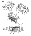
- Figure 1 shows an embodiment where a circuit protection and control device short circuit primary actuator assembly comprising of a frame 15, a primary winding 14, a moulding 12 & a spring 10 has combined entirely within its physical space a magnetic latch solenoid as an independent secondary actuator.
- the primary actuator further comprises of a combined function housing 8 which functions as a primary actuator plunger & a secondary actuator housing which is then allowed to slide within the moulding 12 against the force of the spring 10.
- the secondary independent actuator comprises the combined function housing 8 made from a magnetic material which isolates the internal secondary actuator components from the effects of the magnetic field generated from the current in the primary actuator winding 14.
- the combined function housing 8 has an internal non magnetic region 6 which magnetically isolates the secondary actuator magnetic circuit component 3 from the combined function housing 8.
- Internal to the magnetic circuit component 3 is the secondary actuator magnetic plunger 1 which is held on the plunger plate 2 by a permanent magnet 4 against the opposing spring 7 force.
- the secondary actuator non magnetic plunger 13 is located within the secondary actuator magnetic plunger 1 and also locates the spring 7.
- the secondary actuator magnetic circuit thus comprises the magnetic circuit component 3, the magnetic plunger 1, the plunger plate 2 and the permanent magnet 4.
- the secondary actuator magnetic circuit is isolated from the magnetic field resulting from the primary actuator winding 14 by the combined function housing 8 and the non magnetic plunger 13 when the secondary actuator is in its non actuating position.
- the secondary actuator further comprises a winding 9 connected to a suitable current source which is wound round a bobbin 5 which also locates the magnetic plunger 1, the plunger plate 2 and the permanent magnet 4.
- the winding terminations 11 pass through a small aperture in the bobbin 5, the magnetic circuit component 3, the non magnetic region 6 and the combined function housing 8.
- the primary actuator functions as follows. In a gross over current or short circuit fault condition, the magnetic field generated by the current in the primary actuator winding 14 pulls the secondary actuator combined function housing 8 towards the centre of the primary actuator winding 14 in the direction of arrow A and against the force of the spring 10. Thus the entire secondary actuator assembly slides within the moulding 12 in the direction of arrow A were the non magnetic plunger 13 contacts the circuit protection and control device trip mechanism to cause the main contacts in the circuit protection and control device to open. When the current is removed from the primary actuator winding 14 due to the main circuit protection and control device contacts being open, the spring 10 forces the combined function housing 8 & thus the entire secondary actuator back in the direction of arrow B to the primary actuator rest position determined by the moulding 12.
- the combined function housing 8 and thus the entire secondary actuator is driven back in the direction of arrow B to the rest position determined by the moulding 12 when the circuit protection and control device main contacts are closed and the circuit protection and control device mechanism forces the non magnetic plunger 13 back in the direction of arrow B along with the entire secondary actuator.
- the secondary independent actuator functions as follows.
- a suitable current pulse is applied to the winding 9 resulting in the magnetic circuit of the secondary actuator being influenced to weaken the holding force of the permanent magnet 4 on the magnetic plunger 1 sufficient so that the spring 7 forces the magnetic plunger 1 and the non magnetic plunger 13 in the direction of arrow A sufficient to engage with the circuit protection and control device mechanism and cause the circuit protection and control device main contacts to open.
- the circuit protection and control device main contacts are closed, the non magnetic plunger 13 and the magnetic plunger 1 are forced back in the direction of arrow B, compressing the spring 7 until the magnetic plunger 1 is in contact with the plunger plate 2 and under the influence of the holding force of the permanent magnet 4 and secondary actuator magnetic circuit.
- the independent function of the secondary actuator is ensured by the magnetic isolation of the secondary actuator due to the combined function housing 8 and the non magnetic plunger 13 isolating the secondary actuator internal magnetic circuit from the effects of the current in the primary actuator winding 14.
- FIG. 2 shows a further embodiment where a circuit protection and control device short circuit primary actuator assembly comprising of a frame 15, a primary winding 14, a moulding 12 & a spring 10 has combined entirely within its physical space a solenoid as an independent secondary actuator.
- the primary actuator further comprises of a combined function housing 18 which functions as a primary actuator plunger & a secondary actuator housing which is then allowed to slide within the moulding 12 against the force of the spring 10.
- the secondary independent actuator comprises the combined function housing 18 made from a magnetic material which isolates the internal secondary actuator components from the effects of the magnetic field generated from the current in the primary actuator winding 14.
- the secondary actuator non magnetic plunger 19 is located within the secondary actuator magnetic plunger 20 and also locates the spring 10.
- the secondary actuator thus comprises of the combined function housing 18, the magnetic plunger 20, non magnetic plunger 19, the winding 21, the bobbin 22 and the spring 10.
- the secondary actuator magnetic circuit is isolated from the magnetic field resulting from the primary actuator winding 14 by the combined function housing 18 and the non magnetic plunger 19 when the secondary actuator is in its non actuating position.
- the secondary actuator having a winding 21 connected to a suitable current source which is wound round a bobbin 22 which also locates the magnetic plunger 20.
- the winding terminations 11 pass through a small aperture in the bobbin 22 and the combined function housing 18.
- the primary actuator functions as follows. In a gross over current or short circuit fault condition, the magnetic field generated by the current in the primary actuator winding 14 pulls the secondary actuator combined function housing 18 towards the centre of the primary actuator winding 14 in the direction of arrow A and against the force of the spring 10. Thus the entire secondary actuator assembly slides within the moulding 12 in the direction of arrow A were the non magnetic plunger 19 contacts the circuit protection and control device trip mechanism to cause the main contacts in the circuit protection and control device to open.
- the spring 10 forces the combined function housing 18 & thus the entire secondary actuator back in the direction of arrow B to the primary actuator rest position determined by the moulding 12.
- the combined function housing 18 & thus the entire secondary actuator is driven back in the direction of arrow B to the rest position determined by the moulding 12 when the circuit protection and control device main contacts are closed and the circuit protection and control device mechanism forces the non magnetic plunger 19 back in the direction of arrow B along with the entire secondary actuator.
- the secondary independent actuator functions as follows. A suitable current is applied to the winding 21 resulting in the magnetic plunger 20 being forced in the direction of arrow A against the force of the spring 10 moving toward the axial mid point of the winding 21 sufficient to enable the non magnetic plunger 19 to engage with the circuit protection and control device mechanism and cause the circuit protection and control device main contacts to open. When the current is removed from the winding 21 the force of the spring 10 will return the magnetic plunger 20 & the non magnetic plunger 19 back in the direction of arrow B to their start position.
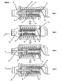
- Figure 3 shows an example embodiment where a circuit protection and control device short circuit primary actuator assembly comprising of a frame 15, a primary winding 14, a moulding 12 & a spring 10 has combined entirely within its physical space a solenoid as an independent secondary actuator.
- the primary actuator further comprises of a combined function housing 18 which functions as a primary actuator plunger & a secondary actuator housing which is then allowed to slide within the moulding 12 against the force of the spring 10.
- the secondary independent actuator comprises the combined function housing 18 made from a magnetic material which isolates the internal secondary actuator components from the effects of the magnetic field generated from the current in the primary actuator winding 14.
- the secondary actuator non magnetic plunger 19 is located within the secondary actuator magnetic plunger 20 and also locates the spring 10.
- the secondary actuator thus comprises of the combined function housing 18, the magnetic plunger 20, non magnetic plunger 19, the winding 21, the bobbin 22 and the spring 10.
- the secondary actuator magnetic circuit is isolated from the magnetic field resulting from the primary actuator winding 14 by the combined function housing 18 and the non magnetic plunger 19 when the secondary actuator is in its non actuating position.
- the secondary actuator having a winding 21 connected to a suitable current source which is wound round a bobbin 22 which also locates the magnetic plunger 20.
- the winding terminations 11 pass through a small aperture in the bobbin 22 and the combined function housing 18.
- the embodiment example functions as follows.
- Stage 1 shows the primary & secondary actuators at rest.
- Stage 2 shows the primary actuator functioning in this example in a gross over current or short circuit fault condition
- the magnetic field generated by the current in the primary actuator winding 14 pulls the secondary actuator combined function housing 18 towards the centre of the primary actuator winding 14 in the direction of arrow A and against the force of the spring 10 which is compressed.
- the entire secondary actuator assembly slides within the moulding 12 in the direction of arrow A were the non magnetic plunger 19 engaged with the circuit protection and control device mechanism results in the main contacts of the circuit protection and control device to open.
- Stage 3 shows when the current is removed from the primary actuator winding 14 due to the main circuit protection and control device contacts being open, the spring 10 decompresses and thus forces the combined function housing 18 & thus the entire secondary actuator back in the direction of arrow B to the primary actuator rest position determined by the moulding 12 with the exception of the non magnetic plunger 19 and the magnetic plunger 20 which remain engaged with the mechanism in the open position.
- Stage 4 shows a suitable current is applied to the winding 21 resulting in the magnetic plunger 20 being forced in the direction of arrow B moving toward the axial mid point of the winding 21 sufficient to enable the non magnetic plunger 19 engaged with the circuit protection and control device mechanism to cause the circuit protection and control device main contacts to close.
- the non magnetic plunger 19 and the magnetic plunger 20 are driven back in the direction of arrow B to the rest position determined by the bobbin 22 when the circuit protection and control device main contacts are manually closed, thus the engaged mechanism forces the non magnetic plunger 19 and the magnetic plunger 20 back in the direction of arrow B to the rest position determined by the bobbin 22.
Description
- An actuator is typically used in electrical protection devices as a means to break a circuit after a fault condition has been detected.
- The most common embodiments of an actuator used in electrical protection devices are typically a relay or a solenoid both having some form of plunger or lever which travels a set distance to interface with a mechanism that determines the contact state.
- The physical space required for such actuators can be considerable relative to the remaining physical space in a standard circuit protection and control device. This problem becomes significant in a miniature circuit protection and control device and significantly contributes to a design compromise between circuit protection and control device cost, overall dimensions and performance.
-
DE 3339400A1 ,US3914720 andEP 1873807A1 each describe switches that include a tripping device, wherein a circuit may be triggered either by a standard actuator or by a solenoid-driven tripping circuit, each being located on a common axis, each resulting in a significant increase in the circuit protection and control device overall dimensions. - Circuit protection and control device current rating and short circuit fault breaking capacity are key functions that contribute to the size of a circuit protection and control device in terms of primary current path conductor size in relation to the maximum current rating of the circuit protection and control device and the size of the arc extinguishing components in relation to the short circuit breaking capacity.
- Circuit protection and control device over current fault protection functionality is typically provided by a bimetal which due to its size and actuating action requires a significant portion of the available space within a circuit protection and control device.
- When additional functionality such as earth leakage current protection or arc fault protection is added to a circuit protection and control device the design compromise between functionality and available space is at its most challenging within a standard miniature circuit protection and control device.
- The space required by the differential current sensor and the additional actuation typically forced a significant increase in the circuit protection and control device overall dimensions resulting in either an increase in device overall height or width. This problem is added to further by specific generic types of circuit protection and control device technology, namely voltage dependant and voltage independent type circuit protection and control device technology. The differential current sensor in a voltage independent circuit protection and control device is significantly larger than is typical in a voltage dependant circuit protection and control device due mainly to the need for the current induced in the secondary winding from the differential fault current to be sufficient to power the actuator to trip the circuit protection and control device mechanism and open the primary conductor path contacts. A magnetic latch relay is the typical actuation method used in a voltage independent circuit protection and control device due to the minimal amount of current required to change the relay state. The size and manufactured cost of these relays are typically larger and higher than a solenoid used in a voltage dependant circuit protection and control device.
- These problems have become a major factor in the commercialisation of circuit protection and control devices and in particular miniature circuit protection and control devices with the size verses cost verses performance criteria being the key selling point in a commodity based market.
- This invention overcomes and resolves these problems by combining tripping functionality typically taking up a large amount of available space within a circuit protection and control device into the space taken by a single actuator.
- This invention combines two independent actuators in the physical space typically taken up by a solenoid assembly used in a circuit protection and control device to provide actuation in the case of a short circuit or gross over current fault condition.
- This invention describes an actuation means combining two independent actuators occupying the three dimensional space used by a single actuator characterized by a primary actuator and a secondary actuator whereby the secondary actuator is the plunger of the primary actuator said secondary actuator construction is further characterized by a combined function housing in which the secondary actuator components are located said combined function housing acting to isolate the magnetic field generated by the windings of the primary actuator from the magnetic components of said secondary actuator.
- This invention further describes the said actuation means used to open & close a circuit protection device characterized by at least a pair of separable contacts in the line or plurality of conductor paths used for controlling the current supplied to a load circuit, the contacts being operated by a mechanism which uses an actuator as its stimulus to open & close said contacts the actuator having two independent means of tripping said circuit protection device and constructed in a manner where both tripping means occupy the three dimensional physical space used for a single tripping means the actuator is characterized as having a primary and secondary actuator.
- The primary actuator can be used as a means to trip a mechanism as a result of a short circuit condition.
- The primary actuator is a solenoid characterized by a primary winding, molding, frame and spring, the plunger which is driven against the force of a spring during a gross over current fault condition to move the plunger towards the centre of the solenoid windings. The plunger engages with the circuit protection and control device mechanism to open the main circuit protection and control device contacts. The combination of the spring and magnitude of the over current determine the rate at which the device opens the circuit protection and control device contacts and thus complying with the requirement of the relevant circuit protection and control device standards.
- The secondary actuator is the primary actuator plunger. The primary actuator plunger comprises a combined function housing for the secondary actuator which isolates the magnetic circuit within the secondary actuator from the magnetic field developed by the primary actuator and a winding to generate a magnetic field within the secondary actuator.
- The combined function housing is characterized by a magnetic external housing, a non magnetic region which magnetically isolates the secondary actuator magnetic circuit however the combined function housing may also be characterized by a magnetic external housing, non magnetic region which magnetically isolates the secondary actuator.
- The secondary actuator is characterized by a secondary actuator plunger comprising of a magnetic portion and a non magnetic portion the magnetic portion is contained within the magnetic circuit component & is contained within the combined function housing non magnetic region. The non magnetic portion of the plunger is a combined interface function for the primary & secondary actuator
- The secondary actuator can be a solenoid, magnetic latch solenoid or mechanical latch solenoid. In all cases the secondary actuator comprises of a bobbin and either a winding or plurality of windings. The terminations for the secondary actuator windings pass through the combined function housing.
- An embodiment of this invention has as the secondary actuator a magnetic latch solenoid comprises a combined function housing, spring, magnetic plunger, non magnetic plunger, permanent magnet, plunger plate, bobbin and winding which utilises a permanent magnet in circuit with a plunger plate, a secondary plunger in which the magnetic portion is held by a permanent magnet and the inner portion of the primary actuator plunger and housing.
- A secondary actuator can be used as a means to trip a mechanism as a result of a over current fault condition, earth leakage fault condition, arc fault condition, under voltage fault condition, over voltage fault condition, loss of neutral fault condition, as a result of an internal component failure condition which renders the device unsafe, a result of a command from an external or remote location, an energy usage limit, a signal embedded in the line voltage and as a result of a DC residual current fault condition.
- This embodiment of a secondary actuator has a coil wound around a bobbin which the secondary plunger passes through and when the coil has a small amount of pulsed current applied will act on the magnetic circuit sufficiently to weaken the magnetic holding force of the permanent magnet on the secondary plunger sufficient to allow the force of a secondary actuating spring to pull the secondary plunger away from the plunger plate and the non magnetic portion of the secondary plunger to engage with the circuit protection and control device mechanism to trip or open the main circuit protection and control device contacts. The secondary actuator is reset by the action of the circuit protection and control device mechanism when the circuit protection and control device main contacts are closed thus forcing the secondary plunger to engage with the plunger plate and the holding force of the permanent magnet and compressing the secondary actuating spring. This embodiment of a combination of two independent actuators in the same space typically used by a circuit protection and control device which uses a solenoid assembly to provide actuation in the case of a short circuit or gross over current fault condition can be used in either a voltage independent or voltage dependant circuit protection and control device for tripping or opening the main circuit protection and control device contacts in response to a plurality of fault conditions or functional requirements.
- A further embodiment of this invention has as the secondary actuator a mechanical latch solenoid comprises a combined function housing, spring, magnetic plunger, non magnetic plunger, mechanical latch, bobbin and winding
- This embodiment of a secondary actuator has a coil wound around a bobbin which the secondary plunger passes through and when the coil has a small amount of pulsed current applied will act on the secondary plunger sufficiently to weaken the mechanical latch holding force on the secondary plunger sufficient to allow the force of a secondary actuating spring to pull the secondary plunger away from the mechanical latch and the non magnetic portion of the secondary plunger to engage with the circuit protection and control device mechanism to trip or open the main circuit protection and control device contacts. The secondary actuator is reset by the action of the circuit protection and control device mechanism when the circuit protection and control device main contacts are closed thus forcing the secondary plunger to engage with the mechanical latch and compress the secondary actuating spring. This embodiment of a combination of two independent actuators in the same space typically used by a circuit protection and control device which uses a solenoid assembly to provide actuation in the case of a short circuit or gross over current fault condition can be used in either a voltage independent or voltage dependant circuit protection and control device for tripping or opening the main circuit protection and control device contacts in response to a plurality of fault conditions or functional requirements.
- A further embodiment of this invention has as the secondary actuator a solenoid comprises a combined function housing, pole piece, firming ring, magnetic plunger, non magnetic plunger, bobbin and winding. This embodiment of a secondary actuator has a pole piece, a firming ring, a secondary plunger which the non magnetic portion is located within the secondary actuator magnetic portion and is held in position by an opposing spring, a winding around a bobbin all of which the secondary plunger passes through and when sufficient current is applied to the winding will pull the secondary plunger magnetic portion against the force of the primary actuator spring to move to engage with the pole piece, the firming ring preventing buzzing when AC current is applied and thus the non magnetic portion of the secondary plunger to engage with the circuit protection and control device mechanism to trip or open the main circuit protection and control device contacts. The secondary actuator is reset when the current to the secondary winding is removed and the primary actuator spring returns the secondary plunger back to its rest position. This embodiment is suitable for a voltage dependant circuit protection and control device due to the increased amount of current required in the secondary actuator windings to move the secondary plunger.
- A further embodiment of this invention has as a secondary actuator a solenoid comprises a combined function housing, magnetic plunger, non magnetic plunger, bobbin and winding. This secondary actuator is located within the primary actuator plunger and when sufficient current is applied to the winding will pull the secondary plunger which the non magnetic portion is located within the secondary actuator magnetic portion and is held in position by an opposing spring, to the centre of the windings against the force of the primary actuator spring and the non magnetic portion of the secondary plunger to engage with the circuit protection and control device mechanism to trip or open the circuit protection and control device main contacts. The secondary actuator is reset when the current to the secondary winding is removed and the primary actuator spring returns the secondary plunger back to its rest position. The primary actuator plunger also acts as a housing having the means to isolate the secondary plunger from the effects of the magnetic field generated from the winding of the primary actuator in an over current or gross over current fault condition. This embodiment can be used in a voltage dependant circuit protection and control device due to the increased amount of current required in the secondary actuator windings to move the secondary plunger.
- In the case of all the embodiments the primary or secondary actuators can be physically configured to operate in opposite axial directions or in the same axial direction thus enabling a suitable mechanism to open the main contacts of a circuit protection and control device with either the primary or secondary actuator and subsequently using either the primary or secondary actuator to act upon the mechanism to close the main contacts of a circuit protection and control device dependant on sufficient energy being available to the actuator when the main contacts are open.
- Therefore, a further embodiment of this invention has the combined primary and secondary actuation utilised in a circuit protection and control device to open and close at least a pair of separable contacts in the line or plurality of conductor paths used for controlling the current supplied to a load circuit, the contacts being operated by a mechanism which uses an actuator as its stimulus to open and close said contacts the actuator having two independent means of opening or closing the said circuit protection and control device contacts and constructed in a manner where both actuation means occupy the three dimensional physical space used for a single actuation means the actuator is characterized as having a primary and secondary actuator. Sufficient energy to enable actuation of either the primary or secondary actuator to engage the mechanism to close the main contacts can be sourced from the input side of the device, a capacitor, a battery, a mechanical energy store such as a spring or mechanism, a solar cell or an independent power supply. In an example of such an embodiment the primary actuator functions to open the main contacts of the circuit protection and control device by engaging the primary plunger against the force of the spring with the mechanism as a result of a short circuit fault condition. The secondary actuator being the plunger of the primary actuator is a solenoid comprises a combined function housing, magnetic plunger, non magnetic plunger , bobbin and winding with the secondary plunger which the non magnetic portion engages with a mechanism so when the device main contacts are open the magnetic portion of the secondary actuator will be asymmetrical about the centre of the secondary actuator winding with the spring in compression held by the mechanism. A suitable current is placed on the winding as a result of a command from an external or remote location or control electronics or such current derived from a sensor, the magnetic plunger will be draw to the centre of the secondary actuator winding, the spring compression will release and thus move the mechanism to close the main contacts of the circuit protection and control device. This embodiment will also allow the circuit protection and control device to be opened and closed by a human manual action.
- Application examples of this embodiment example are by no means limited to open and close an energy metering device, a means to open and close a device when receiving a signal embedded in the line voltage, a means to open and close a device which can be mounted on the front face of a circuit protection and control device or circuit control device, a means to open and close a device as a result of an over current fault condition, a means to open and close a device as a result of an earth leakage fault condition, a means to open and close a device as a result of an arc fault condition, a means to open and close a device as a result of an under voltage fault condition, a means to open and close a device as a result of an over voltage fault condition, a means to open and close a device as a result of a loss of neutral fault condition, a means to open and close a device as a result of an internal failure condition which renders the device unsafe and as a means to open and close a device as a result of a DC residual fault condition
- In the case of all the embodiments a significant amount of space within a circuit protection and control device is made available by each combined actuator embodiment thus enabling additional functionality to be added to a circuit protection and control device without increasing the overall dimensions of the device.
- According to an aspect of the invention we provide a circuit protection and control device, including: a primary actuator comprising a first solenoid having a primary winding and a primary plunger, configured such that a magnetic field generated by a current in the primary winding causes movement of the primary plunger, characterised in that the primary plunger comprises: a magnetic external housing; a non-magnetic region; and a secondary actuator comprising a second solenoid having magnetic components including a secondary winding and a secondary plunger having a magnetic portion, configured such that the secondary plunger is moveable under the influence of a magnetic field generated by a current in the secondary winding; wherein the non-magnetic region of the primary actuator isolates the magnetic components of the secondary actuator from the effects of the magnetic field generated by the primary winding when the secondary plunger is in a non-actuating position.
- The secondary plunger may include a non-magnetic portion for opening and closing a pair of separable contacts for controlling the current supplied to the circuit.
- The secondary winding may include a plurality of windings.
- The secondary actuator may include a winding that comprises a bobbin.
- The terminations of the secondary winding may pass through the housing of the primary plunger.
- The primary actuator may further include a moulding, a frame and a spring.
- The non-magnetic portion of the second plunger may be moveable to separate the pair of contacts under movement of the primary plunger or the secondary plunger.
- The magnetic portion of the secondary plunger may be releasably held by a permanent magnet.
- A portion of the non-magnetic portion of the secondary plunger may be located within a portion of the secondary plunger, and the non-magnetic portion of the secondary plunger is held in position by an opposing spring.
- The secondary actuator may be a magnetic latch solenoid.
- The secondary actuator may be a mechanical latch solenoid.
- The device may be a voltage dependant circuit protection and control device.
- The device may be a voltage independent or a voltage dependant circuit protection and control device.
- The device may be operable to trip and reset a circuit as a result of one or more of: a short circuit condition, an over current fault condition, an earth leakage fault condition, an arc fault condition, an under voltage fault condition, an over voltage fault condition, a loss of neutral fault condition, an internal component failure condition which renders the device unsafe, a command from an external or remote location, as a result of a DC residual current fault condition, as a result of a energy usage limit, as a result of a signal embedded in the line voltage, as a result of a command from control electronics, as a result of a current derived from a sensor, as a result of a manual human action.
- Current may be provided to one or both of the first winding and second winding from at least one of: a capacitive store of current, a current sourced from an input side of the device, a battery, a solar cell, a mechanical energy store, or an independent power supply.
- The primary and secondary actuators can be configured to operate in axially opposite directions or in the same axial direction.
-
-
Figure 1 shows an embodiment having a magnetic latch solenoid as an independent secondary actuator which is combined within the physical space of a circuit protection and control device primary short circuit or gross over current actuator -
Figure 2 shows an embodiment having a solenoid as an independent secondary actuator which is combined within the physical space of a circuit protection and control device primary short circuit or gross over current actuator -
Figure 3 shows the stages of operation of an embodiment example with the combined primary and secondary actuation utilised to engage with a suitable mechanism to open and close the main contacts of a circuit protection and control device -
Figure 1 shows an embodiment where a circuit protection and control device short circuit primary actuator assembly comprising of aframe 15, a primary winding 14, amoulding 12 & aspring 10 has combined entirely within its physical space a magnetic latch solenoid as an independent secondary actuator. - The primary actuator further comprises of a combined
function housing 8 which functions as a primary actuator plunger & a secondary actuator housing which is then allowed to slide within themoulding 12 against the force of thespring 10. - The secondary independent actuator comprises the combined
function housing 8 made from a magnetic material which isolates the internal secondary actuator components from the effects of the magnetic field generated from the current in the primary actuator winding 14. The combinedfunction housing 8 has an internal non magnetic region 6 which magnetically isolates the secondary actuatormagnetic circuit component 3 from the combinedfunction housing 8. Internal to themagnetic circuit component 3 is the secondary actuatormagnetic plunger 1 which is held on theplunger plate 2 by apermanent magnet 4 against the opposing spring 7 force. The secondary actuator nonmagnetic plunger 13 is located within the secondary actuatormagnetic plunger 1 and also locates the spring 7. The secondary actuator magnetic circuit thus comprises themagnetic circuit component 3, themagnetic plunger 1, theplunger plate 2 and thepermanent magnet 4. The secondary actuator magnetic circuit is isolated from the magnetic field resulting from the primary actuator winding 14 by the combinedfunction housing 8 and the nonmagnetic plunger 13 when the secondary actuator is in its non actuating position. The secondary actuator further comprises a winding 9 connected to a suitable current source which is wound round abobbin 5 which also locates themagnetic plunger 1, theplunger plate 2 and thepermanent magnet 4. The windingterminations 11 pass through a small aperture in thebobbin 5, themagnetic circuit component 3, the non magnetic region 6 and the combinedfunction housing 8. - The primary actuator functions as follows. In a gross over current or short circuit fault condition, the magnetic field generated by the current in the primary actuator winding 14 pulls the secondary actuator combined
function housing 8 towards the centre of the primary actuator winding 14 in the direction of arrow A and against the force of thespring 10. Thus the entire secondary actuator assembly slides within themoulding 12 in the direction of arrow A were the nonmagnetic plunger 13 contacts the circuit protection and control device trip mechanism to cause the main contacts in the circuit protection and control device to open. When the current is removed from the primary actuator winding 14 due to the main circuit protection and control device contacts being open, thespring 10 forces the combinedfunction housing 8 & thus the entire secondary actuator back in the direction of arrow B to the primary actuator rest position determined by themoulding 12. Alternatively, the combinedfunction housing 8 and thus the entire secondary actuator is driven back in the direction of arrow B to the rest position determined by themoulding 12 when the circuit protection and control device main contacts are closed and the circuit protection and control device mechanism forces the nonmagnetic plunger 13 back in the direction of arrow B along with the entire secondary actuator. - The secondary independent actuator functions as follows. A suitable current pulse is applied to the winding 9 resulting in the magnetic circuit of the secondary actuator being influenced to weaken the holding force of the
permanent magnet 4 on themagnetic plunger 1 sufficient so that the spring 7 forces themagnetic plunger 1 and the nonmagnetic plunger 13 in the direction of arrow A sufficient to engage with the circuit protection and control device mechanism and cause the circuit protection and control device main contacts to open. When the circuit protection and control device main contacts are closed, the nonmagnetic plunger 13 and themagnetic plunger 1 are forced back in the direction of arrow B, compressing the spring 7 until themagnetic plunger 1 is in contact with theplunger plate 2 and under the influence of the holding force of thepermanent magnet 4 and secondary actuator magnetic circuit. The independent function of the secondary actuator is ensured by the magnetic isolation of the secondary actuator due to the combinedfunction housing 8 and the nonmagnetic plunger 13 isolating the secondary actuator internal magnetic circuit from the effects of the current in the primary actuator winding 14. -
Figure 2 shows a further embodiment where a circuit protection and control device short circuit primary actuator assembly comprising of aframe 15, a primary winding 14, amoulding 12 & aspring 10 has combined entirely within its physical space a solenoid as an independent secondary actuator. - The primary actuator further comprises of a combined
function housing 18 which functions as a primary actuator plunger & a secondary actuator housing which is then allowed to slide within themoulding 12 against the force of thespring 10. - The secondary independent actuator comprises the combined
function housing 18 made from a magnetic material which isolates the internal secondary actuator components from the effects of the magnetic field generated from the current in the primary actuator winding 14. - The secondary actuator non
magnetic plunger 19 is located within the secondary actuatormagnetic plunger 20 and also locates thespring 10. The secondary actuator thus comprises of the combinedfunction housing 18, themagnetic plunger 20, nonmagnetic plunger 19, the winding 21, thebobbin 22 and thespring 10. The secondary actuator magnetic circuit is isolated from the magnetic field resulting from the primary actuator winding 14 by the combinedfunction housing 18 and the nonmagnetic plunger 19 when the secondary actuator is in its non actuating position. The secondary actuator having a winding 21 connected to a suitable current source which is wound round abobbin 22 which also locates themagnetic plunger 20. The windingterminations 11 pass through a small aperture in thebobbin 22 and the combinedfunction housing 18. - The primary actuator functions as follows. In a gross over current or short circuit fault condition, the magnetic field generated by the current in the primary actuator winding 14 pulls the secondary actuator combined
function housing 18 towards the centre of the primary actuator winding 14 in the direction of arrow A and against the force of thespring 10. Thus the entire secondary actuator assembly slides within themoulding 12 in the direction of arrow A were the nonmagnetic plunger 19 contacts the circuit protection and control device trip mechanism to cause the main contacts in the circuit protection and control device to open. - When the current is removed from the primary actuator winding 14 due to the main circuit protection and control device contacts being open, the
spring 10 forces the combinedfunction housing 18 & thus the entire secondary actuator back in the direction of arrow B to the primary actuator rest position determined by themoulding 12. Alternatively, the combinedfunction housing 18 & thus the entire secondary actuator is driven back in the direction of arrow B to the rest position determined by themoulding 12 when the circuit protection and control device main contacts are closed and the circuit protection and control device mechanism forces the nonmagnetic plunger 19 back in the direction of arrow B along with the entire secondary actuator. - The secondary independent actuator functions as follows. A suitable current is applied to the winding 21 resulting in the
magnetic plunger 20 being forced in the direction of arrow A against the force of thespring 10 moving toward the axial mid point of the winding 21 sufficient to enable the nonmagnetic plunger 19 to engage with the circuit protection and control device mechanism and cause the circuit protection and control device main contacts to open. When the current is removed from the winding 21 the force of thespring 10 will return themagnetic plunger 20 & the nonmagnetic plunger 19 back in the direction of arrow B to their start position. -
Figure 3 shows an example embodiment where a circuit protection and control device short circuit primary actuator assembly comprising of aframe 15, a primary winding 14, amoulding 12 & aspring 10 has combined entirely within its physical space a solenoid as an independent secondary actuator. - The primary actuator further comprises of a combined
function housing 18 which functions as a primary actuator plunger & a secondary actuator housing which is then allowed to slide within themoulding 12 against the force of thespring 10. - The secondary independent actuator comprises the combined
function housing 18 made from a magnetic material which isolates the internal secondary actuator components from the effects of the magnetic field generated from the current in the primary actuator winding 14. - The secondary actuator non
magnetic plunger 19 is located within the secondary actuatormagnetic plunger 20 and also locates thespring 10. The secondary actuator thus comprises of the combinedfunction housing 18, themagnetic plunger 20, nonmagnetic plunger 19, the winding 21, thebobbin 22 and thespring 10. The secondary actuator magnetic circuit is isolated from the magnetic field resulting from the primary actuator winding 14 by the combinedfunction housing 18 and the nonmagnetic plunger 19 when the secondary actuator is in its non actuating position. The secondary actuator having a winding 21 connected to a suitable current source which is wound round abobbin 22 which also locates themagnetic plunger 20. The windingterminations 11 pass through a small aperture in thebobbin 22 and the combinedfunction housing 18. - The embodiment example functions as follows.
-
Stage 1 shows the primary & secondary actuators at rest. -
Stage 2 shows the primary actuator functioning in this example in a gross over current or short circuit fault condition, the magnetic field generated by the current in the primary actuator winding 14 pulls the secondary actuator combinedfunction housing 18 towards the centre of the primary actuator winding 14 in the direction of arrow A and against the force of thespring 10 which is compressed. Thus the entire secondary actuator assembly slides within themoulding 12 in the direction of arrow A were the nonmagnetic plunger 19 engaged with the circuit protection and control device mechanism results in the main contacts of the circuit protection and control device to open. -
Stage 3 shows when the current is removed from the primary actuator winding 14 due to the main circuit protection and control device contacts being open, thespring 10 decompresses and thus forces the combinedfunction housing 18 & thus the entire secondary actuator back in the direction of arrow B to the primary actuator rest position determined by themoulding 12 with the exception of the nonmagnetic plunger 19 and themagnetic plunger 20 which remain engaged with the mechanism in the open position. -
Stage 4 shows a suitable current is applied to the winding 21 resulting in themagnetic plunger 20 being forced in the direction of arrow B moving toward the axial mid point of the winding 21 sufficient to enable the nonmagnetic plunger 19 engaged with the circuit protection and control device mechanism to cause the circuit protection and control device main contacts to close. - Alternatively, the non
magnetic plunger 19 and themagnetic plunger 20 are driven back in the direction of arrow B to the rest position determined by thebobbin 22 when the circuit protection and control device main contacts are manually closed, thus the engaged mechanism forces the nonmagnetic plunger 19 and themagnetic plunger 20 back in the direction of arrow B to the rest position determined by thebobbin 22.
Claims (15)
- A circuit protection and control device, including:a primary actuator comprising a first solenoid having a primary winding (14) and a primary plunger (8,18), configured such that a magnetic field generated by a current in the primary winding (14) causes movement of the primary plunger (8,18),characterised in that the primary plunger (8,18) comprises:a magnetic external housing;a non-magnetic region (6); anda secondary actuator comprising a second solenoid having magnetic components including a secondary winding (9, 21) and a secondary plunger having a magnetic portion (1, 20), configured such that the secondary plunger is moveable under the influence of a magnetic field generated by a current in the secondary winding (9, 21);wherein the non-magnetic region (6) of the primary actuator or the magnetic external housing isolates the magnetic components of the secondary actuator from the effects of the magnetic field generated by the primary winding (14) when the secondary plunger is in a non-actuating position.
- A circuit protection and control device according to claim 1, wherein the secondary plunger includes a non-magnetic portion (13,19) for opening and closing a pair of separable contacts for controlling the current supplied to the circuit.
- A circuit protection and control device according to claim 1 wherein the secondary winding (9,21) includes a plurality of windings.
- A circuit protection and control device according to claim 1 wherein the secondary winding (9, 21) comprises a bobbin (5,22).
- A circuit protection and control device according to claim 1 wherein the terminations of the secondary winding (9,21) pass through the housing of the primary plunger (8,18).
- A circuit protection and control device according to claim 1 wherein the primary actuator further includes a moulding (12), a frame (15) and a primary actuator spring (10).
- A circuit protection and control device according to claim 2 wherein the non-magnetic portion (13, 19) of the secondary plunger is moveable to separate the pair of contacts under movement of the primary plunger (8,18) or the secondary plunger.
- A circuit protection and control device according to claim 1, wherein the magnetic portion (1) of the secondary plunger is releasably held by a permanent magnet (4).
- A circuit protection and control device according to claim 1, in which a portion of the non-magnetic portion (19) of the secondary plunger is located within a portion of the magnetic portion (20) of the secondary plunger, and the non-magnetic portion (19) of the secondary plunger is held in position by an opposing spring (10).
- A circuit protection and control device according to claim 1, wherein the secondary actuator is a magnetic latch solenoid or a mechanical latch solenoid.
- A circuit protection and control device according to claim 1, wherein the device is a voltage dependant circuit protection and control device.
- A circuit protection and control device according to claim 10, wherein the device is a voltage independent or a voltage dependant circuit protection and control device.
- A circuit protection and control device according to claim 1 operable to trip and reset a circuit as a result of one or more of: a short circuit condition, an over current fault condition, an earth leakage fault condition, an arc fault condition, an under voltage fault condition, an over voltage fault condition, a loss of neutral fault condition, an internal component failure condition which renders the device unsafe, a command from an external or remote location, as a result of a DC residual current fault condition, as a result of a energy usage limit, as a result of a signal embedded in the line voltage, as a result of a command from control electronics, as a result of a current derived from a sensor, as a result of a manual human action.
- A circuit protection and control device according to claim 1, wherein current is provided to one or both of the primary winding (14) and secondary winding (9,21) from at least one of: a capacitive store of current, a current sourced from an input side of the device, a battery, a solar cell, a mechanical energy store, or an independent power supply.
- A circuit protection and control device according to claim 1, wherein the primary and secondary actuators can be configured to operate in axially opposite directions or in the same axial direction.
Priority Applications (1)
| Application Number | Priority Date | Filing Date | Title |
|---|---|---|---|
| EP11004034.2A EP2525382B1 (en) | 2011-05-16 | 2011-05-16 | Combined function circuit protection and control device actuator |
Applications Claiming Priority (1)
| Application Number | Priority Date | Filing Date | Title |
|---|---|---|---|
| EP11004034.2A EP2525382B1 (en) | 2011-05-16 | 2011-05-16 | Combined function circuit protection and control device actuator |
Publications (2)
| Publication Number | Publication Date |
|---|---|
| EP2525382A1 EP2525382A1 (en) | 2012-11-21 |
| EP2525382B1 true EP2525382B1 (en) | 2015-12-02 |
Family
ID=44581896
Family Applications (1)
| Application Number | Title | Priority Date | Filing Date |
|---|---|---|---|
| EP11004034.2A Not-in-force EP2525382B1 (en) | 2011-05-16 | 2011-05-16 | Combined function circuit protection and control device actuator |
Country Status (1)
| Country | Link |
|---|---|
| EP (1) | EP2525382B1 (en) |
Families Citing this family (1)
| Publication number | Priority date | Publication date | Assignee | Title |
|---|---|---|---|---|
| CN103594295B (en) * | 2013-11-08 | 2015-11-25 | 上海诺雅克电气有限公司 | The trip gear of residual current action breaker |
Family Cites Families (3)
| Publication number | Priority date | Publication date | Assignee | Title |
|---|---|---|---|---|
| DE2348613C2 (en) * | 1973-09-27 | 1975-11-06 | Siemens Ag, 1000 Berlin Und 8000 Muenchen | Circuit breakers, especially circuit breakers |
| DE3339400A1 (en) * | 1983-10-29 | 1985-05-09 | Sursum Elektrizitätsgesellschaft Leyhausen GmbH & Co, 8500 Nürnberg | SELF-SWITCH WITH PITCH ARM RELEASE |
| FR2903223B1 (en) * | 2006-06-29 | 2008-08-15 | Schneider Electric Ind Sas | ELECTRICAL PROTECTION APPARATUS CONTROLLED BY AN AUXILIARY CONTROL DEVICE. |
-
2011
- 2011-05-16 EP EP11004034.2A patent/EP2525382B1/en not_active Not-in-force
Also Published As
| Publication number | Publication date |
|---|---|
| EP2525382A1 (en) | 2012-11-21 |
Similar Documents
| Publication | Publication Date | Title |
|---|---|---|
| KR101044423B1 (en) | Circuit breaker and method for switch the same | |
| JP4590409B2 (en) | Power switch | |
| US8692636B2 (en) | Bistable magnetic actuator for a medium voltage circuit breaker | |
| JPS6258095B2 (en) | ||
| KR20150006058A (en) | Dropout recloser | |
| WO2007063394A3 (en) | Circuit breaker including open neutral interlock | |
| JP2001103724A (en) | Electromagnetic actuator | |
| CA2859108C (en) | Electrical switching apparatus with embedded arc fault protection and system employing same | |
| CA2624387A1 (en) | Magnetostrictive electrical switching device | |
| WO2008139533A1 (en) | Electronic overload relay | |
| EP2779191B1 (en) | Trip actuator for switch of electric power circuit | |
| EP2136383B1 (en) | A control device for an automatic reset apparatus | |
| EP2525382B1 (en) | Combined function circuit protection and control device actuator | |
| US20130009731A1 (en) | Magnetic actuator | |
| JP2019096575A (en) | Vacuum circuit breaker | |
| CN105830189B (en) | Flux shunt device trip actuator interface and breaker for breaker reset mechanism | |
| EP3493236B1 (en) | Noncontact solenoid for miniature circuit breakers with a movable frame and magnetic coupling | |
| CN105047491A (en) | Anti-pumping device of permanent-magnet operation mechanism | |
| CA2531211A1 (en) | Manual trip control method and arrangement for multiple circuit interrupters | |
| EP3130001B1 (en) | Multi-purpose mounting for an electrical switching apparatus | |
| CN205194636U (en) | Permanent magnetism operating device anti -bouncing device | |
| US9805896B2 (en) | Mechanically operated switching device and related switchgear having a movable member for operating the switching device | |
| CN103329223B (en) | There is the electromagnetic driver of low pressure release | |
| CN112820596A (en) | Coaxial circuit breaker tripping device | |
| EP2335264B1 (en) | Low voltage circuit breaker |
Legal Events
| Date | Code | Title | Description |
|---|---|---|---|
| PUAI | Public reference made under article 153(3) epc to a published international application that has entered the european phase |
Free format text: ORIGINAL CODE: 0009012 |
|
| AK | Designated contracting states |
Kind code of ref document: A1 Designated state(s): AL AT BE BG CH CY CZ DE DK EE ES FI FR GB GR HR HU IE IS IT LI LT LU LV MC MK MT NL NO PL PT RO RS SE SI SK SM TR |
|
| AX | Request for extension of the european patent |
Extension state: BA ME |
|
| 17P | Request for examination filed |
Effective date: 20130509 |
|
| GRAP | Despatch of communication of intention to grant a patent |
Free format text: ORIGINAL CODE: EPIDOSNIGR1 |
|
| RIC1 | Information provided on ipc code assigned before grant |
Ipc: H01H 51/00 20060101AFI20150609BHEP Ipc: H01H 71/24 20060101ALI20150609BHEP |
|
| INTG | Intention to grant announced |
Effective date: 20150624 |
|
| RIN1 | Information on inventor provided before grant (corrected) |
Inventor name: LEWIS, CARL, JUSTIN Inventor name: GANLEY, SEAN CHRISTOHER |
|
| GRAS | Grant fee paid |
Free format text: ORIGINAL CODE: EPIDOSNIGR3 |
|
| GRAA | (expected) grant |
Free format text: ORIGINAL CODE: 0009210 |
|
| AK | Designated contracting states |
Kind code of ref document: B1 Designated state(s): AL AT BE BG CH CY CZ DE DK EE ES FI FR GB GR HR HU IE IS IT LI LT LU LV MC MK MT NL NO PL PT RO RS SE SI SK SM TR |
|
| REG | Reference to a national code |
Ref country code: GB Ref legal event code: FG4D |
|
| REG | Reference to a national code |
Ref country code: AT Ref legal event code: REF Ref document number: 763956 Country of ref document: AT Kind code of ref document: T Effective date: 20151215 Ref country code: CH Ref legal event code: EP |
|
| REG | Reference to a national code |
Ref country code: IE Ref legal event code: FG4D |
|
| REG | Reference to a national code |
Ref country code: DE Ref legal event code: R096 Ref document number: 602011021746 Country of ref document: DE |
|
| REG | Reference to a national code |
Ref country code: NL Ref legal event code: MP Effective date: 20160302 |
|
| REG | Reference to a national code |
Ref country code: LT Ref legal event code: MG4D |
|
| REG | Reference to a national code |
Ref country code: AT Ref legal event code: MK05 Ref document number: 763956 Country of ref document: AT Kind code of ref document: T Effective date: 20151202 |
|
| PG25 | Lapsed in a contracting state [announced via postgrant information from national office to epo] |
Ref country code: ES Free format text: LAPSE BECAUSE OF FAILURE TO SUBMIT A TRANSLATION OF THE DESCRIPTION OR TO PAY THE FEE WITHIN THE PRESCRIBED TIME-LIMIT Effective date: 20151202 Ref country code: NO Free format text: LAPSE BECAUSE OF FAILURE TO SUBMIT A TRANSLATION OF THE DESCRIPTION OR TO PAY THE FEE WITHIN THE PRESCRIBED TIME-LIMIT Effective date: 20160302 Ref country code: LT Free format text: LAPSE BECAUSE OF FAILURE TO SUBMIT A TRANSLATION OF THE DESCRIPTION OR TO PAY THE FEE WITHIN THE PRESCRIBED TIME-LIMIT Effective date: 20151202 |
|
| REG | Reference to a national code |
Ref country code: FR Ref legal event code: PLFP Year of fee payment: 6 |
|
| PG25 | Lapsed in a contracting state [announced via postgrant information from national office to epo] |
Ref country code: GR Free format text: LAPSE BECAUSE OF FAILURE TO SUBMIT A TRANSLATION OF THE DESCRIPTION OR TO PAY THE FEE WITHIN THE PRESCRIBED TIME-LIMIT Effective date: 20160303 Ref country code: FI Free format text: LAPSE BECAUSE OF FAILURE TO SUBMIT A TRANSLATION OF THE DESCRIPTION OR TO PAY THE FEE WITHIN THE PRESCRIBED TIME-LIMIT Effective date: 20151202 Ref country code: SE Free format text: LAPSE BECAUSE OF FAILURE TO SUBMIT A TRANSLATION OF THE DESCRIPTION OR TO PAY THE FEE WITHIN THE PRESCRIBED TIME-LIMIT Effective date: 20151202 Ref country code: RS Free format text: LAPSE BECAUSE OF FAILURE TO SUBMIT A TRANSLATION OF THE DESCRIPTION OR TO PAY THE FEE WITHIN THE PRESCRIBED TIME-LIMIT Effective date: 20151202 Ref country code: LV Free format text: LAPSE BECAUSE OF FAILURE TO SUBMIT A TRANSLATION OF THE DESCRIPTION OR TO PAY THE FEE WITHIN THE PRESCRIBED TIME-LIMIT Effective date: 20151202 Ref country code: NL Free format text: LAPSE BECAUSE OF FAILURE TO SUBMIT A TRANSLATION OF THE DESCRIPTION OR TO PAY THE FEE WITHIN THE PRESCRIBED TIME-LIMIT Effective date: 20151202 Ref country code: AT Free format text: LAPSE BECAUSE OF FAILURE TO SUBMIT A TRANSLATION OF THE DESCRIPTION OR TO PAY THE FEE WITHIN THE PRESCRIBED TIME-LIMIT Effective date: 20151202 Ref country code: PL Free format text: LAPSE BECAUSE OF FAILURE TO SUBMIT A TRANSLATION OF THE DESCRIPTION OR TO PAY THE FEE WITHIN THE PRESCRIBED TIME-LIMIT Effective date: 20151202 |
|
| PG25 | Lapsed in a contracting state [announced via postgrant information from national office to epo] |
Ref country code: IS Free format text: LAPSE BECAUSE OF FAILURE TO SUBMIT A TRANSLATION OF THE DESCRIPTION OR TO PAY THE FEE WITHIN THE PRESCRIBED TIME-LIMIT Effective date: 20151202 |
|
| PG25 | Lapsed in a contracting state [announced via postgrant information from national office to epo] |
Ref country code: IT Free format text: LAPSE BECAUSE OF FAILURE TO SUBMIT A TRANSLATION OF THE DESCRIPTION OR TO PAY THE FEE WITHIN THE PRESCRIBED TIME-LIMIT Effective date: 20151202 Ref country code: CZ Free format text: LAPSE BECAUSE OF FAILURE TO SUBMIT A TRANSLATION OF THE DESCRIPTION OR TO PAY THE FEE WITHIN THE PRESCRIBED TIME-LIMIT Effective date: 20151202 |
|
| PG25 | Lapsed in a contracting state [announced via postgrant information from national office to epo] |
Ref country code: BE Free format text: LAPSE BECAUSE OF NON-PAYMENT OF DUE FEES Effective date: 20160531 Ref country code: RO Free format text: LAPSE BECAUSE OF FAILURE TO SUBMIT A TRANSLATION OF THE DESCRIPTION OR TO PAY THE FEE WITHIN THE PRESCRIBED TIME-LIMIT Effective date: 20151202 Ref country code: SK Free format text: LAPSE BECAUSE OF FAILURE TO SUBMIT A TRANSLATION OF THE DESCRIPTION OR TO PAY THE FEE WITHIN THE PRESCRIBED TIME-LIMIT Effective date: 20151202 Ref country code: PT Free format text: LAPSE BECAUSE OF FAILURE TO SUBMIT A TRANSLATION OF THE DESCRIPTION OR TO PAY THE FEE WITHIN THE PRESCRIBED TIME-LIMIT Effective date: 20160404 Ref country code: EE Free format text: LAPSE BECAUSE OF FAILURE TO SUBMIT A TRANSLATION OF THE DESCRIPTION OR TO PAY THE FEE WITHIN THE PRESCRIBED TIME-LIMIT Effective date: 20151202 Ref country code: SM Free format text: LAPSE BECAUSE OF FAILURE TO SUBMIT A TRANSLATION OF THE DESCRIPTION OR TO PAY THE FEE WITHIN THE PRESCRIBED TIME-LIMIT Effective date: 20151202 Ref country code: IS Free format text: LAPSE BECAUSE OF FAILURE TO SUBMIT A TRANSLATION OF THE DESCRIPTION OR TO PAY THE FEE WITHIN THE PRESCRIBED TIME-LIMIT Effective date: 20160402 |
|
| REG | Reference to a national code |
Ref country code: DE Ref legal event code: R097 Ref document number: 602011021746 Country of ref document: DE |
|
| PLBE | No opposition filed within time limit |
Free format text: ORIGINAL CODE: 0009261 |
|
| STAA | Information on the status of an ep patent application or granted ep patent |
Free format text: STATUS: NO OPPOSITION FILED WITHIN TIME LIMIT |
|
| PG25 | Lapsed in a contracting state [announced via postgrant information from national office to epo] |
Ref country code: DK Free format text: LAPSE BECAUSE OF FAILURE TO SUBMIT A TRANSLATION OF THE DESCRIPTION OR TO PAY THE FEE WITHIN THE PRESCRIBED TIME-LIMIT Effective date: 20151202 |
|
| 26N | No opposition filed |
Effective date: 20160905 |
|
| PG25 | Lapsed in a contracting state [announced via postgrant information from national office to epo] |
Ref country code: SI Free format text: LAPSE BECAUSE OF FAILURE TO SUBMIT A TRANSLATION OF THE DESCRIPTION OR TO PAY THE FEE WITHIN THE PRESCRIBED TIME-LIMIT Effective date: 20151202 |
|
| PG25 | Lapsed in a contracting state [announced via postgrant information from national office to epo] |
Ref country code: BE Free format text: LAPSE BECAUSE OF FAILURE TO SUBMIT A TRANSLATION OF THE DESCRIPTION OR TO PAY THE FEE WITHIN THE PRESCRIBED TIME-LIMIT Effective date: 20151202 Ref country code: LU Free format text: LAPSE BECAUSE OF FAILURE TO SUBMIT A TRANSLATION OF THE DESCRIPTION OR TO PAY THE FEE WITHIN THE PRESCRIBED TIME-LIMIT Effective date: 20160516 |
|
| REG | Reference to a national code |
Ref country code: CH Ref legal event code: PL |
|
| PG25 | Lapsed in a contracting state [announced via postgrant information from national office to epo] |
Ref country code: LI Free format text: LAPSE BECAUSE OF NON-PAYMENT OF DUE FEES Effective date: 20160531 Ref country code: CH Free format text: LAPSE BECAUSE OF NON-PAYMENT OF DUE FEES Effective date: 20160531 |
|
| REG | Reference to a national code |
Ref country code: IE Ref legal event code: MM4A |
|
| REG | Reference to a national code |
Ref country code: FR Ref legal event code: PLFP Year of fee payment: 7 |
|
| PG25 | Lapsed in a contracting state [announced via postgrant information from national office to epo] |
Ref country code: IE Free format text: LAPSE BECAUSE OF NON-PAYMENT OF DUE FEES Effective date: 20160516 |
|
| PGFP | Annual fee paid to national office [announced via postgrant information from national office to epo] |
Ref country code: DE Payment date: 20170509 Year of fee payment: 7 Ref country code: FR Payment date: 20170511 Year of fee payment: 7 Ref country code: GB Payment date: 20170510 Year of fee payment: 7 |
|
| PG25 | Lapsed in a contracting state [announced via postgrant information from national office to epo] |
Ref country code: HU Free format text: LAPSE BECAUSE OF FAILURE TO SUBMIT A TRANSLATION OF THE DESCRIPTION OR TO PAY THE FEE WITHIN THE PRESCRIBED TIME-LIMIT; INVALID AB INITIO Effective date: 20110516 Ref country code: CY Free format text: LAPSE BECAUSE OF FAILURE TO SUBMIT A TRANSLATION OF THE DESCRIPTION OR TO PAY THE FEE WITHIN THE PRESCRIBED TIME-LIMIT Effective date: 20151202 |
|
| PG25 | Lapsed in a contracting state [announced via postgrant information from national office to epo] |
Ref country code: TR Free format text: LAPSE BECAUSE OF FAILURE TO SUBMIT A TRANSLATION OF THE DESCRIPTION OR TO PAY THE FEE WITHIN THE PRESCRIBED TIME-LIMIT Effective date: 20151202 Ref country code: MT Free format text: LAPSE BECAUSE OF NON-PAYMENT OF DUE FEES Effective date: 20160531 Ref country code: HR Free format text: LAPSE BECAUSE OF FAILURE TO SUBMIT A TRANSLATION OF THE DESCRIPTION OR TO PAY THE FEE WITHIN THE PRESCRIBED TIME-LIMIT Effective date: 20151202 Ref country code: MK Free format text: LAPSE BECAUSE OF FAILURE TO SUBMIT A TRANSLATION OF THE DESCRIPTION OR TO PAY THE FEE WITHIN THE PRESCRIBED TIME-LIMIT Effective date: 20151202 Ref country code: MC Free format text: LAPSE BECAUSE OF FAILURE TO SUBMIT A TRANSLATION OF THE DESCRIPTION OR TO PAY THE FEE WITHIN THE PRESCRIBED TIME-LIMIT Effective date: 20151202 |
|
| PG25 | Lapsed in a contracting state [announced via postgrant information from national office to epo] |
Ref country code: BG Free format text: LAPSE BECAUSE OF FAILURE TO SUBMIT A TRANSLATION OF THE DESCRIPTION OR TO PAY THE FEE WITHIN THE PRESCRIBED TIME-LIMIT Effective date: 20151202 |
|
| PG25 | Lapsed in a contracting state [announced via postgrant information from national office to epo] |
Ref country code: AL Free format text: LAPSE BECAUSE OF FAILURE TO SUBMIT A TRANSLATION OF THE DESCRIPTION OR TO PAY THE FEE WITHIN THE PRESCRIBED TIME-LIMIT Effective date: 20151202 |
|
| REG | Reference to a national code |
Ref country code: DE Ref legal event code: R119 Ref document number: 602011021746 Country of ref document: DE |
|
| GBPC | Gb: european patent ceased through non-payment of renewal fee |
Effective date: 20180516 |
|
| PG25 | Lapsed in a contracting state [announced via postgrant information from national office to epo] |
Ref country code: DE Free format text: LAPSE BECAUSE OF NON-PAYMENT OF DUE FEES Effective date: 20181201 Ref country code: GB Free format text: LAPSE BECAUSE OF NON-PAYMENT OF DUE FEES Effective date: 20180516 Ref country code: FR Free format text: LAPSE BECAUSE OF NON-PAYMENT OF DUE FEES Effective date: 20180531 |