EP2525263A2 - Image forming apparatus - Google Patents
Image forming apparatus Download PDFInfo
- Publication number
- EP2525263A2 EP2525263A2 EP12165925A EP12165925A EP2525263A2 EP 2525263 A2 EP2525263 A2 EP 2525263A2 EP 12165925 A EP12165925 A EP 12165925A EP 12165925 A EP12165925 A EP 12165925A EP 2525263 A2 EP2525263 A2 EP 2525263A2
- Authority
- EP
- European Patent Office
- Prior art keywords
- section
- toner
- image forming
- image
- forming apparatus
- Prior art date
- Legal status (The legal status is an assumption and is not a legal conclusion. Google has not performed a legal analysis and makes no representation as to the accuracy of the status listed.)
- Granted
Links
- 238000001514 detection method Methods 0.000 claims abstract description 34
- 230000015572 biosynthetic process Effects 0.000 claims abstract description 21
- 238000004140 cleaning Methods 0.000 description 8
- 230000002159 abnormal effect Effects 0.000 description 6
- 230000003287 optical effect Effects 0.000 description 6
- 238000012546 transfer Methods 0.000 description 5
- 238000012545 processing Methods 0.000 description 4
- 230000000903 blocking effect Effects 0.000 description 3
- 238000011161 development Methods 0.000 description 3
- 238000010586 diagram Methods 0.000 description 2
- 239000011521 glass Substances 0.000 description 2
- 239000000463 material Substances 0.000 description 2
- 238000000034 method Methods 0.000 description 2
- 230000004044 response Effects 0.000 description 2
- 230000005856 abnormality Effects 0.000 description 1
- 230000001464 adherent effect Effects 0.000 description 1
- XAGFODPZIPBFFR-UHFFFAOYSA-N aluminium Chemical compound [Al] XAGFODPZIPBFFR-UHFFFAOYSA-N 0.000 description 1
- 229910052782 aluminium Inorganic materials 0.000 description 1
- 229910021417 amorphous silicon Inorganic materials 0.000 description 1
- 239000003086 colorant Substances 0.000 description 1
- 230000007246 mechanism Effects 0.000 description 1
- 238000012986 modification Methods 0.000 description 1
- 230000004048 modification Effects 0.000 description 1
- 108091008695 photoreceptors Proteins 0.000 description 1
- 229920001909 styrene-acrylic polymer Polymers 0.000 description 1
- 230000032258 transport Effects 0.000 description 1
- 238000001771 vacuum deposition Methods 0.000 description 1
- 239000002699 waste material Substances 0.000 description 1
Images


Classifications
-
- G—PHYSICS
- G03—PHOTOGRAPHY; CINEMATOGRAPHY; ANALOGOUS TECHNIQUES USING WAVES OTHER THAN OPTICAL WAVES; ELECTROGRAPHY; HOLOGRAPHY
- G03G—ELECTROGRAPHY; ELECTROPHOTOGRAPHY; MAGNETOGRAPHY
- G03G21/00—Arrangements not provided for by groups G03G13/00 - G03G19/00, e.g. cleaning, elimination of residual charge
-
- G—PHYSICS
- G03—PHOTOGRAPHY; CINEMATOGRAPHY; ANALOGOUS TECHNIQUES USING WAVES OTHER THAN OPTICAL WAVES; ELECTROGRAPHY; HOLOGRAPHY
- G03G—ELECTROGRAPHY; ELECTROPHOTOGRAPHY; MAGNETOGRAPHY
- G03G15/00—Apparatus for electrographic processes using a charge pattern
- G03G15/55—Self-diagnostics; Malfunction or lifetime display
- G03G15/553—Monitoring or warning means for exhaustion or lifetime end of consumables, e.g. indication of insufficient copy sheet quantity for a job
- G03G15/556—Monitoring or warning means for exhaustion or lifetime end of consumables, e.g. indication of insufficient copy sheet quantity for a job for toner consumption, e.g. pixel counting, toner coverage detection or toner density measurement
-
- G—PHYSICS
- G03—PHOTOGRAPHY; CINEMATOGRAPHY; ANALOGOUS TECHNIQUES USING WAVES OTHER THAN OPTICAL WAVES; ELECTROGRAPHY; HOLOGRAPHY
- G03G—ELECTROGRAPHY; ELECTROPHOTOGRAPHY; MAGNETOGRAPHY
- G03G15/00—Apparatus for electrographic processes using a charge pattern
- G03G15/06—Apparatus for electrographic processes using a charge pattern for developing
- G03G15/08—Apparatus for electrographic processes using a charge pattern for developing using a solid developer, e.g. powder developer
- G03G15/0822—Arrangements for preparing, mixing, supplying or dispensing developer
- G03G15/0848—Arrangements for testing or measuring developer properties or quality, e.g. charge, size, flowability
- G03G15/0856—Detection or control means for the developer level
- G03G15/0862—Detection or control means for the developer level the level being measured by optical means
-
- G—PHYSICS
- G03—PHOTOGRAPHY; CINEMATOGRAPHY; ANALOGOUS TECHNIQUES USING WAVES OTHER THAN OPTICAL WAVES; ELECTROGRAPHY; HOLOGRAPHY
- G03G—ELECTROGRAPHY; ELECTROPHOTOGRAPHY; MAGNETOGRAPHY
- G03G21/00—Arrangements not provided for by groups G03G13/00 - G03G19/00, e.g. cleaning, elimination of residual charge
- G03G21/14—Electronic sequencing control
-
- G—PHYSICS
- G03—PHOTOGRAPHY; CINEMATOGRAPHY; ANALOGOUS TECHNIQUES USING WAVES OTHER THAN OPTICAL WAVES; ELECTROGRAPHY; HOLOGRAPHY
- G03G—ELECTROGRAPHY; ELECTROPHOTOGRAPHY; MAGNETOGRAPHY
- G03G21/00—Arrangements not provided for by groups G03G13/00 - G03G19/00, e.g. cleaning, elimination of residual charge
- G03G21/16—Mechanical means for facilitating the maintenance of the apparatus, e.g. modular arrangements
- G03G21/1604—Arrangement or disposition of the entire apparatus
- G03G21/1623—Means to access the interior of the apparatus
- G03G21/1633—Means to access the interior of the apparatus using doors or covers
Definitions
- the paper sheet P discharged from the fixing section 13 is temporarily sent out from the branch section 14 toward the sheet discharge section 16, and then the transportation direction of the paper sheet P is immediately switched in the second sheet transporting section 15 to a direction toward the right side surface of the main body 2. Then, the paper sheet P passes through the branch section 14, and is sent downward through a sheet transportation path 17 for duplex printing, which is provided on a right side of the fixing section 13 and the transferring section 5. The paper sheet P is again sent to the transferring section 5 via the first sheet transporting section 4.
- Step #105 The user notified that the toner in the toner container 10 is used up performs work of replacing the toner container 10 (Step #105). Note that, in Step #105, the user manually replaces the toner container 10. Meanwhile, the main control section 18 causes the image forming section 30 to continue the image formation for the print job that is being executed.
- the main control section 18 halts the image forming section 30 from executing the image formation (Step #109). Then, the main control section 18 ends the flow of operation in relation to the opening of the openable and closable cover 12 during execution of the print job ("END"). That is, the main control section 18 maintains the state of prohibiting the image forming section 30 from executing the image forming operation until the opening/closing detection sensor 23 can detect the closing of the openable and closable cover 12.
Landscapes
- Physics & Mathematics (AREA)
- General Physics & Mathematics (AREA)
- Control Or Security For Electrophotography (AREA)
- Dry Development In Electrophotography (AREA)
- Electrophotography Configuration And Component (AREA)
- Color Electrophotography (AREA)
- Accessory Devices And Overall Control Thereof (AREA)
Abstract
Description
- The present disclosure relates to an image forming apparatus such as a copying machine, a printer, and a facsimile machine.
- An electrophotographic image forming apparatus such as a copying machine and a printer widely employs a photosensitive drum as an image bearing member. A general image forming operation using the photosensitive drum is carried out in the following manner. A charging section uniformly charges a surface of the photosensitive drum at a predetermined potential. An exposure section irradiates the surface of the photosensitive drum with LED light or the like, and the surface potential optically attenuates in part, to thereby form an electrostatic latent image corresponding to a desired image. A developing section develops the electrostatic latent image to form a toner image on the surface of the photosensitive drum. The toner image is transferred to a paper sheet when the paper sheet passes through a transferring region formed by the photosensitive drum and a transferring member, which are held in contact with or proximity to each other.
- In order to achieve smooth image formation, it is necessary to appropriately grasp and notify a user of a remaining amount of toner as developer stored in the developing section that plays a major role in the image forming operation as described above. The user needs to replenish the toner to the image forming apparatus based on information on the remaining amount of the toner. In view of this, there is an image forming apparatus in which a toner container or a toner cartridge easily replaceable by the user is removably provided to a main body of the image forming apparatus.
- The above-mentioned image forming apparatus includes a toner cartridge mountable to and removable from the main body of the image forming apparatus, a hopper serving as a toner buffer for temporarily storing toner supplied from the toner cartridge and replenishing the toner to the developing section, and detection means for detecting mounting and removal of the toner cartridge. With the hopper provided in the image forming apparatus, even when the removal of the toner cartridge is detected, the print job is continued and the user is prompted to mount the toner cartridge. In a case where a cover to be opened and closed when the toner cartridge is mounted and removed is opened, the image forming apparatus prompts the user to close the cover.
- However, in the above-mentioned image forming apparatus, when the print job is continued in the case where the removal of the toner cartridge is detected, the remaining amount of toner replenished to the developing section from the toner cartridge is not taken into consideration.
- That is, when it is detected that the toner cartridge is removed or the cover is opened under a state in which the toner is used up or almost used up, the toner cartridge is likely to be replaced with a new toner cartridge in a relatively early stage after the detection, which hardly disturbs continuation of the print job. On the other hand, when it is detected that the toner cartridge is removed or the cover is opened under a state in which the toner is sufficiently loaded, some trouble may occur in the image forming apparatus and the user may be unaware of the trouble. As a result, for example, the replenishment of the toner to the developing section is not smoothly performed so that the image quality is lowered, and an unnecessary replenishing operation is repeated even though the toner does not need to be replenished to the developing section so that the operation efficiency is lowered. Therefore, there is a risk that the continuation of the print job is seriously disturbed in the above-mentioned state.
- The present disclosure has been made in view of the above-mentioned matters, and has an object to provide an image forming apparatus capable of correctly determining a normal/abnormal state of the image forming apparatus in relation to opening of an openable and closable cover during execution of a print job, which is to be opened and closed when a toner container is mounted to and removed from a main body of the image forming apparatus, to thereby appropriately control an image forming operation in accordance with the normal/abnormal state. Further, the present disclosure has an object to provide an image forming apparatus capable of obtaining an image with suitable quality and having improved operation efficiency as a result of the control.
- In order to achieve the above-mentioned objects, an image forming apparatus according to an exemplary embodiment of the present disclosure includes an image forming section, a toner container, an intermediate hopper, a remaining amount detection sensor, an openable and closable cover, an opening/closing detection sensor, and a control section. The image forming section includes a developing section for developing an electrostatic latent image formed on a surface of an image bearing member into a toner image through supply of toner to the image bearing member. The image forming section is configured to execute image formation for transferring an image onto a paper sheet. The toner container stores the toner, and is mountable to and removable from a main body of the image forming apparatus. The intermediate hopper stores the toner supplied from the toner container to replenish the toner to the developing section. The remaining amount detection sensor detects a remaining amount of the toner in the intermediate hopper. The openable and closable cover is to be opened and closed when the toner container is mounted to and removed from the main body of the image forming apparatus. The opening/closing detection sensor detects an operation of opening and closing the openable and closable cover. The control section is configured to acquire output from each of the remaining amount detection sensor and the opening/closing detection sensor, and control the image formation executed by the image forming section. During execution of a print job, the control section is configured to cause the image forming section to continue the image formation for the print job that is being executed, when the control section recognizes based on the output acquired from the opening/closing detection sensor that the openable and closable cover is opened, and when the control section recognizes based on the output acquired from the remaining amount detection sensor that an amount of the toner in the intermediate hopper is less than a predetermined amount. Further, the control section is configured to cause the image forming section to halt the image formation for the print job that is being executed, when the control section recognizes based on the output acquired from the opening/closing detection sensor that the openable and closable cover is opened, and when the control section recognizes based on the output acquired from the remaining amount detection sensor that the amount of the toner in the intermediate hopper is the predetermined amount or more.
- Further features and advantages of the present disclosure will become apparent from the description of embodiments given below.
-
-
FIG. 1 is a schematic vertically-sectional front view of an image forming apparatus according to an embodiment of the present disclosure. -
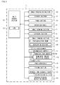
FIG. 2 is a block diagram illustrating a configuration of the image forming apparatus according to the embodiment of the present disclosure. -
FIG. 3 is a vertically-sectional partial front view illustrating an image forming section and its vicinity in the image forming apparatus according to the embodiment of the present disclosure. -
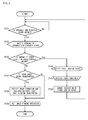
FIG. 4 is a flow chart illustrating an operation in relation to opening of an openable and closable cover during execution of a print job in the image forming apparatus according to the embodiment of the present disclosure. - Hereinafter, an embodiment of the present disclosure is described with reference to
FIGS. 1 to 4 . Note that, elements such as components and arrangements described in the embodiment are not limitations to the scope of the disclosure but merely examples for description thereof. - First, with regard to an image forming apparatus according to the embodiment of the present disclosure, an image output operation is described by referring to
FIGS. 1 and2 while describing an outline structure and configuration thereof.FIG. 1 is a schematic vertically-sectional front view of the image forming apparatus, andFIG. 2 is a block diagram illustrating the configuration of the image forming apparatus. InFIG. 1 , the chain line arrow indicates a laser beam L. - As illustrated in
FIG. 1 , animage forming apparatus 1 includes amain body 2, inside whichsheet feeding cassettes 3 are arranged on a lower side thereof. Thesheet feeding cassette 3 stores therein a bundle of paper sheets P as recording media, such as cut sheets to be subjected to printing. The paper sheets P are separately sent out one by one toward a top right side of thesheet feeding cassette 3 ofFIG. 1 . Thesheet feeding cassette 3 can be pulled out horizontally from a front surface side of themain body 2. - A first
sheet transporting section 4 is provided inside themain body 2 on a right side of thesheet feeding cassette 3. The firstsheet transporting section 4 is formed substantially vertically along a right side surface of themain body 2. The firstsheet transporting section 4 receives the paper sheet P sent out from thesheet feeding cassette 3, and transports the paper sheet P to a transferringsection 5 vertically upward along the right side surface of themain body 2. - On the other hand, an
original transporting device 6 is mounted above themain body 2 of theimage forming apparatus 1, and animage reading section 7 is mounted inside themain body 2 below theoriginal transporting device 6. When a user performs copying of an original, originals on which images of characters, graphics, patterns, and the like are drawn are stacked on theoriginal transporting device 6, or each original is placed on a contact glass (not shown) on an upper surface of theimage reading section 7. Theoriginal transporting device 6 separately sends out the originals one by one, and theimage reading section 7 reads an image of each original. Theimage reading section 7 reads an image of the original placed on the contact glass through scanning of light performed inside theimage reading section 7. - The start of reading of the original image and printing is instructed with use of an
operation panel 8 provided on an upper right side of theimage forming apparatus 1. Theoperation panel 8 is provided so as to project upward from themain body 2. Further, theoperation panel 8 serves as an operation section for receiving settings performed by the user on printing conditions, such as a type and size of the paper sheet P to be used for printing, resizing, and a setting on duplex printing, and for receiving instructions to indicate an error state and to cancel the indication. Theoperation panel 8 serves also as a notification section for notifying the user of, for example, a state of the image forming apparatus, notices, and error messages which are displayed on adisplay section 8a. - Information on image data on the original is subjected to image processing via a main control section and an image processing section to be described later, and is then sent to an
exposure section 9 arranged above thesheet feeding cassette 3 at a center part of themain body 2. Theexposure section 9 irradiates animage forming section 30 with the laser beam L controlled based on the image data. - The
image forming section 30 and the transferringsection 5 are provided above the firstsheet transporting section 4 on a right side of theexposure section 9. In theimage forming section 30, an electrostatic latent image corresponding to the original image is formed by the laser beam L irradiated by theexposure section 9, and a toner image is developed from the electrostatic latent image. Toner is supplied from atoner container 10 provided at an upper part of themain body 2 to anintermediate hopper 11 provided below thetoner container 10 and above theexposure section 9. The toner is replenished to theimage forming section 30 from theintermediate hopper 11. The toner image formed by theimage forming section 30 is transferred by the transferringsection 5 onto the paper sheet P before printing, which is sent by the firstsheet transporting section 4 in synchronization with the formation of the toner image. - The
toner container 10 is mountable to and removable from themain body 2. For the mounting and removal of thetoner container 10, an openable andclosable cover 12 is provided in the front surface of themain body 2. Thetoner container 10 is mountable to and removable from themain body 2 through an opening appearing when the openable andclosable cover 12 is opened toward the front side. - A fixing
section 13 is provided above the transferringsection 5 and theimage forming section 30. The paper sheet P having an unfixed toner image borne at thetransferring section 5 is sent to the fixingsection 13, and a heat roller and a pressure roller heat and pressurize the toner image so that the toner image is fixed to the paper sheet P. - A
branch section 14 is provided above the fixingsection 13. When the duplex printing is not performed, the paper sheet P discharged from the fixingsection 13 is transported from thebranch section 14 through a secondsheet transporting section 15 extending substantially horizontally toward a left side surface of themain body 2, and is discharged to asheet discharge section 16 provided outside themain body 2 at the upper part of the left side surface of themain body 2. - When the duplex printing is performed, the paper sheet P discharged from the fixing
section 13 is temporarily sent out from thebranch section 14 toward thesheet discharge section 16, and then the transportation direction of the paper sheet P is immediately switched in the secondsheet transporting section 15 to a direction toward the right side surface of themain body 2. Then, the paper sheet P passes through thebranch section 14, and is sent downward through asheet transportation path 17 for duplex printing, which is provided on a right side of the fixingsection 13 and thetransferring section 5. The paper sheet P is again sent to thetransferring section 5 via the firstsheet transporting section 4. - As illustrated in
FIG. 2 , for operation control of the entireimage forming apparatus 1, theimage forming apparatus 1 further includes, inside themain body 2 thereof, amain control section 18 formed of a central processing unit (CPU) 19 and other such electronic components (not shown). Themain control section 18 uses theCPU 19 and animage processing section 20 to implement a series of image forming operations by controlling the components such as theimage reading section 7, theexposure section 9, theimage forming section 30, and the fixingsection 13 based on a program and data stored in and input to astorage section 21. Theimage forming apparatus 1 further includes atimer section 22 for measuring time, to thereby grasp various kinds of time necessary for the image forming operation. - An opening/
closing detection sensor 23 is provided at a location corresponding to the location of the openable andclosable cover 12. For example, the opening/closing detection sensor 23 is constructed with use of a transmissive optical sensor provided to themain body 2 and a blocking plate provided to the openable andclosable cover 12, for blocking light from the optical sensor under a closed state of the openable andclosable cover 12. The blocking plate moves along with an operation of opening and closing the openable andclosable cover 12, and accordingly the level of a signal output from the optical sensor is switched. In response to the output from the opening/closing detection sensor 23, themain control section 18 detects the opened state or the closed state of the openable andclosable cover 12. - Next, in addition to
FIGS. 1 and2 , reference is made toFIG. 3 to describe the detailed configuration of theimage forming section 30 and its vicinity.FIG. 3 is a vertically-sectional partial front view illustrating the image forming section and its vicinity. - As illustrated in
FIG. 3 , theimage forming section 30 includes aphotosensitive drum 31 serving as an image bearing member at the center thereof. In the vicinity of thephotosensitive drum 31, a chargingsection 32, a developingsection 33, and acleaning section 34 are arranged in the stated order along a rotational direction of thephotosensitive drum 31. The transferringsection 5 is provided between the developingsection 33 and thecleaning section 34 along the rotational direction of thephotosensitive drum 31. - The
photosensitive drum 31 extends in a sheet width direction orthogonal to the sheet transportation direction in theimage forming apparatus 1, that is, in a depth direction of the drawing sheet ofFIG. 3 . Thephotosensitive drum 31 is arranged with its axial direction kept horizontal. Thephotosensitive drum 31 is an inorganic photoreceptor drum, in which a photosensitive layer made of amorphous silicon as an inorganic photoconductive material is provided by vacuum deposition or the like on an outer side of a conductive roller-like base material made of aluminum or the like. For example, thephotosensitive drum 31 has a diameter of 30 mm. Thephotosensitive drum 31 rotates counterclockwise inFIG. 3 by a drive section (not shown) so that a circumferential speed thereof substantially equals the sheet transportation speed (for example, 230 mm/sec). - The charging
section 32 is a scorotron charging device using a corona charger, which is arranged on a substantially left side of thephotosensitive drum 31. Note that, the chargingsection 32 may be a corotron charging device similarly using a corona charger, or a contact charging device such as a charging roller and a charging brush. The chargingsection 32 uniformly charges a surface of thephotosensitive drum 31 at a predetermined polarity and potential. At this time, the charging potential is generally +350 V, for example. - The developing
section 33 is arranged below thephotosensitive drum 31, and includes a developingroller 33b inside ahousing 33a thereof. The development method using the developingroller 33b involves, for example, magnetic toner projection development, and the developingroller 33b is provided in the vicinity of thephotosensitive drum 31. A developing bias having the same polarity as the charging polarity of thephotosensitive drum 31 is applied to the developingroller 33b. The developingroller 33b charges toner as developer, and moves and supplies the toner to the electrostatic latent image formed on the surface of thephotosensitive drum 31, to thereby develop the electrostatic latent image. - The toner is, for example, styrene acrylic magnetic single component toner, and is stored in the
toner container 10 illustrated inFIG. 1 . The toner is transported by a toner transporting mechanism (not shown) to the developingsection 33 via theintermediate hopper 11, and is replenished to atoner storage chamber 33c provided inside thehousing 33a of the developingsection 33. Note that, the development method and the kind of toner applied to the developingsection 33 are not limited to the above. - The transferring
section 5 is arranged on a substantially right side of thephotosensitive drum 31, and includes a transferringroller 5a. The transferringroller 5 a is held in press contact with thephotosensitive drum 31 from the right side ofFIG. 3 , and forms a transfer nip portion, through which the paper sheet P passes, between the transferringroller 5a and thephotosensitive drum 31. The transferringroller 5 a is held in contact with thephotosensitive drum 31 to rotate without a drive device in accordance with the rotation of thephotosensitive drum 31. A transfer bias of, for example, -500 V to -1,000 V having a polarity different from the charging polarity of thephotosensitive drum 31 and the toner is applied to the transferringroller 5 a as necessary. - The
cleaning section 34 is arranged above thephotosensitive drum 31, and includes, inside ahousing 34a thereof, a cleaningroller 34b, acleaning blade 34c, and atoner discharge screw 34d. The cleaningroller 34b and thecleaning blade 34c are held in press contact with thephotosensitive drum 31, and clean thephotosensitive drum 31 by removing adherents such as toner remaining on the surface of thephotosensitive drum 31. The toner or the like removed from the surface of thephotosensitive drum 31 is sent toward thetoner discharge screw 34d, and is discharged by thetoner discharge screw 34d to a waste toner collecting container (not shown) provided outside thecleaning section 34. - As illustrated in
FIGS. 1 and2 , theintermediate hopper 11 for replenishing toner to thetoner storage chamber 33c of the developingsection 33 is provided with a remainingamount detection sensor 11a for detecting a remaining amount of the toner in theintermediate hopper 11. For example, the remainingamount detection sensor 11a is constructed with use of a transmissive optical sensor. When at least a predetermined amount of toner is present in theintermediate hopper 11, light from the optical sensor is blocked so that the level of a signal output from the optical sensor is switched. In response to the output from the remainingamount detection sensor 11a, themain control section 18 detects that theintermediate hopper 11 is filled with at least the predetermined amount of toner, that is, the amount of the toner suffices to continue the image forming operation. - Note that, based on the output acquired from the remaining
amount detection sensor 11a, when the amount of the toner in theintermediate hopper 11 is less than the predetermined amount, that is, under a state in which the toner is not supplied from thetoner container 10, themain control section 18 recognizes that thetoner container 10 is in a toner used-up state. When thetoner container 10 is in the toner used-up state, themain control section 18 uses thedisplay section 8a of theoperation panel 8 serving as the notification section to notify the user of the toner used-up state, and prompts the user to replace thetoner container 10. - When the
toner container 10 is replaced, it is necessary to open the openable andclosable cover 12 provided in the front surface of themain body 2. Themain control section 18 correctly determines a normal/abnormal state of the image forming apparatus in relation to the opening of the openable andclosable cover 12 during execution of a print job, to thereby appropriately control the image forming operation in accordance with the normal/abnormal state. - Next, an operation in relation to the opening of the openable and
closable cover 12 during execution of the print job in theimage forming apparatus 1 is described with reference to a flow illustrated inFIG. 4. FIG. 4 is a flow chart illustrating the operation in relation to the opening of the openable andclosable cover 12 during execution of the print job. - When the print job is executed in the image forming apparatus 1 ("START"), the
main control section 18 determines based on the output acquired from the opening/closing detection sensor 23 whether or not the openable andclosable cover 12 is in the opened state (Step #101). When themain control section 18 recognizes that the openable andclosable cover 12 is in the closed state ("No" in Step #101), themain control section 18 causes theimage forming apparatus 1 to normally operate. On the other hand, when themain control section 18 recognizes that the openable andclosable cover 12 is in the opened state ("Yes" in Step #101), themain control section 18 causes thedisplay section 8a of theoperation panel 8 serving as the notification section to display an indication that the openable andclosable cover 12 is in the opened state, to thereby notify the user of the opened state of the openable and closable cover 12 (Step #102). - Subsequently, the
main control section 18 determines based on the output acquired from the remainingamount detection sensor 11a whether or not the amount of the toner in theintermediate hopper 11 is less than the predetermined amount (Step #103). When themain control section 18 recognizes that the amount of the toner in theintermediate hopper 11 is less than the predetermined amount ("Yes" in Step #103), themain control section 18 causes thedisplay section 8a of theoperation panel 8 to display an indication that thetoner container 10 is in the toner used-up state, to thereby notify the user of the toner used-up state of thetoner container 10, and prompts the user to replace the toner container 10 (Step #104). - The user notified that the toner in the
toner container 10 is used up performs work of replacing the toner container 10 (Step #105). Note that, inStep # 105, the user manually replaces thetoner container 10. Meanwhile, themain control section 18 causes theimage forming section 30 to continue the image formation for the print job that is being executed. - When the user finishes the work of replacing the
toner container 10, themain control section 18 recognizes that the amount of the toner in theintermediate hopper 11 has become the predetermined amount or more, and accordingly cancels the determination state in which thetoner container 10 is in the toner used-up state (Step #106). Further, themain control section 18 stops the indication displayed on theoperation panel 8 for prompting the user to replace thetoner container 10. Then, themain control section 18 causes theimage forming apparatus 1 to normally operate through the determination that the amount of the toner in theintermediate hopper 11 suffices to continue the image forming operation (returns to Step #101). - On the other hand, when the
main control section 18 determines inStep # 103 that the amount of the toner in theintermediate hopper 11 is the predetermined amount or more ("No" in Step #103), themain control section 18 determines whether or not the paper sheet P is being transported by the firstsheet transporting section 4 toward the transferringsection 5 in the current print job (Step #107). When the paper sheet is being transported ("Yes" in Step #107), themain control section 18 causes theimage forming section 30 to execute the image formation for the paper sheet P that is being transported, and causes thetransferring section 5 to transfer the formed image onto the paper sheet P (Step #108). Then, themain control section 18 prohibits subsequent execution of sheet transportation from thesheet feeding cassette 3. - Subsequently, the
main control section 18 halts theimage forming section 30 from executing the image formation (Step #109). Then, themain control section 18 ends the flow of operation in relation to the opening of the openable andclosable cover 12 during execution of the print job ("END"). That is, themain control section 18 maintains the state of prohibiting theimage forming section 30 from executing the image forming operation until the opening/closing detection sensor 23 can detect the closing of the openable andclosable cover 12. - As described above, in the case where the amount of the toner in the
intermediate hopper 11 is less than the predetermined amount, that is, thetoner container 10 is in the toner used-up state when the openable andclosable cover 12 is opened during execution of the print job, themain control section 18 of theimage forming apparatus 1 determines that the openable andclosable cover 12 is normally opened. Then, themain control section 18 causes theimage forming section 30 to continue the image formation on the assumption that thetoner container 10 is replaced and accordingly the toner is newly replenished. Thus, theimage forming apparatus 1 can smoothly execute the image formation with a sufficient amount of toner, to thereby obtain an image with suitable quality. - On the other hand, in the case where the amount of the toner in the
intermediate hopper 11 is the predetermined amount or more when the openable andclosable cover 12 is opened during execution of the print job, themain control section 18 of theimage forming apparatus 1 determines that the openable andclosable cover 12 is opened because of abnormality. Then, themain control section 18 prohibits theimage forming section 30 from executing the image formation for the risk that some trouble has occurred in the image forming apparatus. Thus, theimage forming apparatus 1 can suppress an unnecessary toner replenishing operation for the developingsection 33, for example, to thereby improve operation efficiency. - Note that, even in a case where the openable and
closable cover 12 is opened and themain control section 18 recognizes that the amount of the toner in theintermediate hopper 11 is the predetermined amount or more, themain control section 18 of theimage forming apparatus 1 allows the image formation to be executed for the paper sheet P that is being transported toward the transferringsection 5, and allows thetransferring section 5 to transfer the formed image onto the paper sheet P. After that, themain control section 18 halts the image formation. Thus, it is possible to prevent theimage forming apparatus 1 from such an incomplete state that the paper sheet P is stopped in the middle of transportation. - Further, the
image forming apparatus 1 includes theoperation panel 8 serving as the notification section for notifying the user of the opened state of the openable andclosable cover 12, and hence the user can promptly recognize the opened state of the openable andclosable cover 12. Thus, the user can quickly deal with the trouble caused by the fact that the openable andclosable cover 12 is opened even though the amount of the toner in theintermediate hopper 11 is the predetermined amount or more. - The
operation panel 8 serves also as the notification section for notifying the user of the event that themain control section 18 recognizes based on the output acquired from the remainingamount detection sensor 11a that the amount of the toner in theintermediate hopper 11 is less than the predetermined amount. Accordingly, the user can promptly recognize that thetoner container 10 is in the toner used-up state. Thus, the user can quickly replace thetoner container 10. - According to the configuration of the above-mentioned embodiment, it is possible to provide the
image forming apparatus 1 capable of correctly determining the normal/abnormal state of the image forming apparatus in relation to the opening of the openable andclosable cover 12 during execution of the print job, which is to be opened and closed when thetoner container 10 is mounted to and removed from themain body 2 of theimage forming apparatus 1, to thereby appropriately control the image forming operation in accordance with the normal/abnormal state. Further, it is possible to provide theimage forming apparatus 1 capable of obtaining an image with suitable quality and having improved operation efficiency as a result of the control. - In the above, the embodiment of the present disclosure has been described. However, the scope of the present disclosure is not limited thereto, and the present disclosure may be implemented by being subjected to various modifications without departing from the gist of the present disclosure.
- For example, the above-mentioned embodiment has been described by taking, as an example of the
image forming apparatus 1, an image forming apparatus for monochrome printing with use of only black toner. However, the image forming apparatus to which the present disclosure is applied is not limited to such an image forming apparatus. The image forming apparatus to which the present disclosure is applied may be a tandem or rotary image forming apparatus for color printing, including an intermediate transfer belt, thereby being capable of forming an image of a plurality of colors overlaid one on top of another.
The above embodiments of the invention as well as the appended claims and figures show multiple characterizing features of the invention in specific combinations. The skilled person will easily be able to consider further combinations or sub-combinations of these features in order to adapt the invention as defined in the claims to his specific needs.
Claims (4)
- An image forming apparatus, comprising:an image forming section (30) including a developing section (33) for developing an electrostatic latent image formed on a surface of an image bearing member (31) into a toner image through supply of toner to the image bearing member (31), the image forming section (30) being configured to execute image formation for transferring an image onto a paper sheet (P);a toner container (10) for storing the toner, the toner container (10) being mountable to and removable from a main body (2) of the image forming apparatus (1);an intermediate hopper (11)for storing the toner supplied from the toner container (10) to replenish the toner to the developing section (33);a remaining amount detection sensor (11a) for detecting a remaining amount of the toner in the intermediate hopper (11);an openable and closable cover (12) to be opened and closed when the toner container (10) is mounted to and removed from the main body (2) of the image forming apparatus (1);an opening/closing detection sensor (23) for detecting an operation of opening and closing the openable and closable cover (12); anda control section (18) configured to acquire output from each of the remaining amount detection sensor (11a) and the opening/closing detection sensor (23), and control the image formation executed by the image forming section (30),the image forming apparatus (1) being characterized in that, during execution of a print job, the control section (18) is configured to cause the image forming section (30) to:continue the image formation for the print job that is being executed, when the control section (18) recognizes based on the output acquired from the opening/closing detection sensor (23) that the openable and closable cover (12) is opened, and when the control section (18) recognizes based on the output acquired from the remaining amount detection sensor (11a) that an amount of the toner in the intermediate hopper (11) is less than a predetermined amount; andhalt the image formation for the print job that is being executed, when the control section (18) recognizes based on the output acquired from the opening/closing detection sensor (23) that the openable and closable cover (12) is opened, and when the control section (18) recognizes based on the output acquired from the remaining amount detection sensor (11a) that the amount of the toner in the intermediate hopper (11) is the predetermined amount or more.
- An image forming apparatus according to claim 1, characterized by further comprising a sheet transporting section (4) for transporting the paper sheet toward a transferring section (5) for transferring, onto the paper sheet (P), the image formed by the image forming section (30),
the image forming apparatus being characterized in that, when the paper sheet (P) is being transported by the sheet transporting section (4) toward the transferring section (5), when the control section (18) recognizes that the openable and closable cover (12) is opened, and when the control section (18) recognizes that the amount of the toner in the intermediate hopper (11) is the predetermined amount or more, the control section (18) is configured to cause the image forming section (33) to halt the image formation after the image is transferred onto the paper sheet (P) that is being transported. - An image forming apparatus according to claim 1 or 2, characterized by further comprising a notification section (8a) for notifying a user of an opened state of the openable and closable cover (12).
- An image forming apparatus according to claim 1, characterized by further comprising a notification section (8a) for notifying a user of an event that the control section (18) recognizes based on the output acquired from the remaining amount detection sensor (11a) that the amount of the toner in the intermediate hopper (11) is less than the predetermined amount.
Applications Claiming Priority (1)
| Application Number | Priority Date | Filing Date | Title |
|---|---|---|---|
| JP2011111074A JP5323123B2 (en) | 2011-05-18 | 2011-05-18 | Image forming apparatus |
Publications (3)
| Publication Number | Publication Date |
|---|---|
| EP2525263A2 true EP2525263A2 (en) | 2012-11-21 |
| EP2525263A3 EP2525263A3 (en) | 2017-04-26 |
| EP2525263B1 EP2525263B1 (en) | 2018-10-31 |
Family
ID=45999720
Family Applications (1)
| Application Number | Title | Priority Date | Filing Date |
|---|---|---|---|
| EP12165925.4A Not-in-force EP2525263B1 (en) | 2011-05-18 | 2012-04-27 | Image forming apparatus |
Country Status (5)
| Country | Link |
|---|---|
| US (1) | US8948622B2 (en) |
| EP (1) | EP2525263B1 (en) |
| JP (1) | JP5323123B2 (en) |
| KR (1) | KR101316174B1 (en) |
| CN (1) | CN102789156B (en) |
Cited By (1)
| Publication number | Priority date | Publication date | Assignee | Title |
|---|---|---|---|---|
| EP3358421A1 (en) * | 2017-02-07 | 2018-08-08 | Kabushiki Kaisha Toshiba | Image formation apparatus and alert transmission method |
Families Citing this family (12)
| Publication number | Priority date | Publication date | Assignee | Title |
|---|---|---|---|---|
| JP6124461B2 (en) * | 2013-07-25 | 2017-05-10 | 京セラドキュメントソリューションズ株式会社 | Image forming apparatus |
| JP6557978B2 (en) | 2015-01-21 | 2019-08-14 | ブラザー工業株式会社 | Inkjet recording apparatus and program |
| JP6547303B2 (en) * | 2015-01-21 | 2019-07-24 | ブラザー工業株式会社 | Ink jet recording apparatus and program |
| JP6390444B2 (en) | 2015-01-21 | 2018-09-19 | ブラザー工業株式会社 | Inkjet recording apparatus and program |
| US20160223979A1 (en) * | 2015-01-30 | 2016-08-04 | Canon Kabushiki Kaisha | Cartridge, process cartridge, and image forming apparatus |
| JP2016142878A (en) * | 2015-01-30 | 2016-08-08 | キヤノン株式会社 | Cartridge, process cartridge, and image forming apparatus |
| JP6808499B2 (en) * | 2017-01-11 | 2021-01-06 | キヤノン株式会社 | Image processing device, control method of image processing device, and program |
| JP7107062B2 (en) * | 2018-07-26 | 2022-07-27 | 京セラドキュメントソリューションズ株式会社 | image forming device |
| EP3940461A4 (en) | 2019-03-15 | 2022-12-14 | Canon Kabushiki Kaisha | IMAGE FORMING DEVICE |
| JP7458828B2 (en) * | 2019-03-15 | 2024-04-01 | キヤノン株式会社 | Image forming device |
| CN113727858B (en) * | 2019-04-30 | 2024-03-29 | 惠普发展公司,有限责任合伙企业 | Displaying current colorant supply status information in response to opening of a printing device door |
| JP2025082546A (en) * | 2023-11-17 | 2025-05-29 | 京セラドキュメントソリューションズ株式会社 | Image forming apparatus |
Family Cites Families (22)
| Publication number | Priority date | Publication date | Assignee | Title |
|---|---|---|---|---|
| JPH05181364A (en) * | 1992-01-07 | 1993-07-23 | Fuji Xerox Co Ltd | Image forming device |
| JPH06208263A (en) * | 1993-01-12 | 1994-07-26 | Canon Inc | Image forming device |
| US5790917A (en) * | 1995-10-30 | 1998-08-04 | Canon Kabushiki Kaisha | Developing device having a residual toner amount discrimination feature and image forming apparatus using same |
| JP2000162925A (en) * | 1998-11-30 | 2000-06-16 | Canon Inc | Image forming apparatus and control method thereof |
| JP2000187414A (en) * | 1998-12-24 | 2000-07-04 | Ricoh Co Ltd | Toner magazine detection method and recording apparatus using the same |
| JP2001305845A (en) * | 2000-04-18 | 2001-11-02 | Fuji Xerox Co Ltd | Image forming device |
| JP2002062763A (en) * | 2000-08-18 | 2002-02-28 | Canon Inc | Image forming apparatus, control method for image forming apparatus, and storage medium |
| JP3969045B2 (en) * | 2001-10-03 | 2007-08-29 | 富士ゼロックス株式会社 | Printing device |
| JP2005084072A (en) * | 2003-09-04 | 2005-03-31 | Konica Minolta Business Technologies Inc | Image forming apparatus |
| JP4380361B2 (en) * | 2004-02-25 | 2009-12-09 | 富士ゼロックス株式会社 | Toner replenishing device, developing device using the same, and image forming apparatus |
| JP2006098490A (en) * | 2004-09-28 | 2006-04-13 | Fuji Xerox Co Ltd | Image forming apparatus |
| US7206528B2 (en) * | 2004-11-12 | 2007-04-17 | Kabushiki Kaisha Toshiba | Image forming apparatus and image forming method |
| JP2006195232A (en) * | 2005-01-14 | 2006-07-27 | Konica Minolta Business Technologies Inc | Image forming apparatus |
| JP4810877B2 (en) * | 2005-04-27 | 2011-11-09 | ブラザー工業株式会社 | Image forming apparatus |
| JP4955963B2 (en) * | 2005-08-31 | 2012-06-20 | キヤノン株式会社 | Image forming apparatus |
| JP2008090210A (en) * | 2006-10-05 | 2008-04-17 | Fuji Xerox Co Ltd | Image forming apparatus |
| JP2008116679A (en) * | 2006-11-02 | 2008-05-22 | Murata Mach Ltd | Image forming apparatus |
| JP5084316B2 (en) * | 2007-03-22 | 2012-11-28 | キヤノン株式会社 | Image forming apparatus |
| JP2009047739A (en) * | 2007-08-13 | 2009-03-05 | Sharp Corp | Toner replenishing device, developing device, and image forming apparatus |
| JP5121579B2 (en) * | 2008-05-30 | 2013-01-16 | キヤノン株式会社 | Image forming apparatus |
| JP5323125B2 (en) * | 2011-05-20 | 2013-10-23 | 京セラドキュメントソリューションズ株式会社 | Image forming apparatus |
| JP2012247699A (en) * | 2011-05-30 | 2012-12-13 | Kyocera Document Solutions Inc | Image forming apparatus |
-
2011
- 2011-05-18 JP JP2011111074A patent/JP5323123B2/en active Active
-
2012
- 2012-04-24 CN CN201210122350.6A patent/CN102789156B/en not_active Expired - Fee Related
- 2012-04-25 KR KR1020120043265A patent/KR101316174B1/en active Active
- 2012-04-27 EP EP12165925.4A patent/EP2525263B1/en not_active Not-in-force
- 2012-04-30 US US13/460,782 patent/US8948622B2/en active Active
Non-Patent Citations (1)
| Title |
|---|
| None |
Cited By (1)
| Publication number | Priority date | Publication date | Assignee | Title |
|---|---|---|---|---|
| EP3358421A1 (en) * | 2017-02-07 | 2018-08-08 | Kabushiki Kaisha Toshiba | Image formation apparatus and alert transmission method |
Also Published As
| Publication number | Publication date |
|---|---|
| EP2525263A3 (en) | 2017-04-26 |
| KR101316174B1 (en) | 2013-10-08 |
| US20120294634A1 (en) | 2012-11-22 |
| JP5323123B2 (en) | 2013-10-23 |
| US8948622B2 (en) | 2015-02-03 |
| EP2525263B1 (en) | 2018-10-31 |
| CN102789156A (en) | 2012-11-21 |
| KR20120129760A (en) | 2012-11-28 |
| CN102789156B (en) | 2014-07-16 |
| JP2012242534A (en) | 2012-12-10 |
Similar Documents
| Publication | Publication Date | Title |
|---|---|---|
| US8948622B2 (en) | Self-monitoring image forming apparatus | |
| JPH0820806B2 (en) | Empty toner detection device for developing device | |
| US11526126B2 (en) | Image forming apparatus | |
| JP2009116001A (en) | Method and device for estimating toner residual amount, and image forming apparatus | |
| CN113515027B (en) | Image forming apparatus and control method | |
| JP6525200B2 (en) | Image forming apparatus and process cartridge | |
| JP2010276804A (en) | Image forming apparatus | |
| JP5074869B2 (en) | Development device | |
| JP5423065B2 (en) | Seal member detection apparatus, image forming apparatus, and seal member detection program | |
| JPH09258620A (en) | Image forming device | |
| JP2010276705A (en) | Image forming apparatus | |
| JP3700473B2 (en) | Toner cartridge replacement detection device and image forming apparatus using the same | |
| JP2014115354A (en) | Apparatus for determining time for ordering waste developer recovery container and image forming apparatus | |
| JP2012247699A (en) | Image forming apparatus | |
| EP4296786A2 (en) | Image forming apparatus | |
| WO2021080637A1 (en) | Waste toner container mounting structure of image forming apparatus | |
| JP2009048112A (en) | Method for controlling conveyance of waste toner for image forming apparatus and image forming apparatus | |
| CN110320768B (en) | Toner container and image forming apparatus | |
| JP4398776B2 (en) | Electrophotographic process apparatus and image forming apparatus having the same | |
| JP2012150258A (en) | Image forming device | |
| JP4820274B2 (en) | Image forming apparatus | |
| JP2022126022A (en) | image forming device | |
| JP2022048442A (en) | Image forming device | |
| JP2022122590A (en) | Developing device, image forming device, developer depletion detection method | |
| JP2011027904A (en) | Toner recycle system, process cartridge including the same, and image forming apparatus |
Legal Events
| Date | Code | Title | Description |
|---|---|---|---|
| PUAI | Public reference made under article 153(3) epc to a published international application that has entered the european phase |
Free format text: ORIGINAL CODE: 0009012 |
|
| AK | Designated contracting states |
Kind code of ref document: A2 Designated state(s): AL AT BE BG CH CY CZ DE DK EE ES FI FR GB GR HR HU IE IS IT LI LT LU LV MC MK MT NL NO PL PT RO RS SE SI SK SM TR |
|
| AX | Request for extension of the european patent |
Extension state: BA ME |
|
| PUAL | Search report despatched |
Free format text: ORIGINAL CODE: 0009013 |
|
| AK | Designated contracting states |
Kind code of ref document: A3 Designated state(s): AL AT BE BG CH CY CZ DE DK EE ES FI FR GB GR HR HU IE IS IT LI LT LU LV MC MK MT NL NO PL PT RO RS SE SI SK SM TR |
|
| AX | Request for extension of the european patent |
Extension state: BA ME |
|
| RIC1 | Information provided on ipc code assigned before grant |
Ipc: G03G 15/00 20060101ALI20170322BHEP Ipc: G03G 15/08 20060101ALI20170322BHEP Ipc: G03G 21/16 20060101AFI20170322BHEP |
|
| STAA | Information on the status of an ep patent application or granted ep patent |
Free format text: STATUS: REQUEST FOR EXAMINATION WAS MADE |
|
| 17P | Request for examination filed |
Effective date: 20171026 |
|
| RBV | Designated contracting states (corrected) |
Designated state(s): AL AT BE BG CH CY CZ DE DK EE ES FI FR GB GR HR HU IE IS IT LI LT LU LV MC MK MT NL NO PL PT RO RS SE SI SK SM TR |
|
| GRAP | Despatch of communication of intention to grant a patent |
Free format text: ORIGINAL CODE: EPIDOSNIGR1 |
|
| STAA | Information on the status of an ep patent application or granted ep patent |
Free format text: STATUS: GRANT OF PATENT IS INTENDED |
|
| INTG | Intention to grant announced |
Effective date: 20180814 |
|
| GRAS | Grant fee paid |
Free format text: ORIGINAL CODE: EPIDOSNIGR3 |
|
| GRAA | (expected) grant |
Free format text: ORIGINAL CODE: 0009210 |
|
| STAA | Information on the status of an ep patent application or granted ep patent |
Free format text: STATUS: THE PATENT HAS BEEN GRANTED |
|
| AK | Designated contracting states |
Kind code of ref document: B1 Designated state(s): AL AT BE BG CH CY CZ DE DK EE ES FI FR GB GR HR HU IE IS IT LI LT LU LV MC MK MT NL NO PL PT RO RS SE SI SK SM TR |
|
| REG | Reference to a national code |
Ref country code: CH Ref legal event code: EP Ref country code: GB Ref legal event code: FG4D |
|
| REG | Reference to a national code |
Ref country code: AT Ref legal event code: REF Ref document number: 1060129 Country of ref document: AT Kind code of ref document: T Effective date: 20181115 |
|
| REG | Reference to a national code |
Ref country code: DE Ref legal event code: R096 Ref document number: 602012052791 Country of ref document: DE |
|
| REG | Reference to a national code |
Ref country code: IE Ref legal event code: FG4D |
|
| REG | Reference to a national code |
Ref country code: NL Ref legal event code: MP Effective date: 20181031 |
|
| REG | Reference to a national code |
Ref country code: LT Ref legal event code: MG4D |
|
| REG | Reference to a national code |
Ref country code: AT Ref legal event code: MK05 Ref document number: 1060129 Country of ref document: AT Kind code of ref document: T Effective date: 20181031 |
|
| PG25 | Lapsed in a contracting state [announced via postgrant information from national office to epo] |
Ref country code: NO Free format text: LAPSE BECAUSE OF FAILURE TO SUBMIT A TRANSLATION OF THE DESCRIPTION OR TO PAY THE FEE WITHIN THE PRESCRIBED TIME-LIMIT Effective date: 20190131 Ref country code: BG Free format text: LAPSE BECAUSE OF FAILURE TO SUBMIT A TRANSLATION OF THE DESCRIPTION OR TO PAY THE FEE WITHIN THE PRESCRIBED TIME-LIMIT Effective date: 20190131 Ref country code: PL Free format text: LAPSE BECAUSE OF FAILURE TO SUBMIT A TRANSLATION OF THE DESCRIPTION OR TO PAY THE FEE WITHIN THE PRESCRIBED TIME-LIMIT Effective date: 20181031 Ref country code: ES Free format text: LAPSE BECAUSE OF FAILURE TO SUBMIT A TRANSLATION OF THE DESCRIPTION OR TO PAY THE FEE WITHIN THE PRESCRIBED TIME-LIMIT Effective date: 20181031 Ref country code: LT Free format text: LAPSE BECAUSE OF FAILURE TO SUBMIT A TRANSLATION OF THE DESCRIPTION OR TO PAY THE FEE WITHIN THE PRESCRIBED TIME-LIMIT Effective date: 20181031 Ref country code: LV Free format text: LAPSE BECAUSE OF FAILURE TO SUBMIT A TRANSLATION OF THE DESCRIPTION OR TO PAY THE FEE WITHIN THE PRESCRIBED TIME-LIMIT Effective date: 20181031 Ref country code: AT Free format text: LAPSE BECAUSE OF FAILURE TO SUBMIT A TRANSLATION OF THE DESCRIPTION OR TO PAY THE FEE WITHIN THE PRESCRIBED TIME-LIMIT Effective date: 20181031 Ref country code: IS Free format text: LAPSE BECAUSE OF FAILURE TO SUBMIT A TRANSLATION OF THE DESCRIPTION OR TO PAY THE FEE WITHIN THE PRESCRIBED TIME-LIMIT Effective date: 20190228 Ref country code: HR Free format text: LAPSE BECAUSE OF FAILURE TO SUBMIT A TRANSLATION OF THE DESCRIPTION OR TO PAY THE FEE WITHIN THE PRESCRIBED TIME-LIMIT Effective date: 20181031 Ref country code: FI Free format text: LAPSE BECAUSE OF FAILURE TO SUBMIT A TRANSLATION OF THE DESCRIPTION OR TO PAY THE FEE WITHIN THE PRESCRIBED TIME-LIMIT Effective date: 20181031 |
|
| PG25 | Lapsed in a contracting state [announced via postgrant information from national office to epo] |
Ref country code: AL Free format text: LAPSE BECAUSE OF FAILURE TO SUBMIT A TRANSLATION OF THE DESCRIPTION OR TO PAY THE FEE WITHIN THE PRESCRIBED TIME-LIMIT Effective date: 20181031 Ref country code: SE Free format text: LAPSE BECAUSE OF FAILURE TO SUBMIT A TRANSLATION OF THE DESCRIPTION OR TO PAY THE FEE WITHIN THE PRESCRIBED TIME-LIMIT Effective date: 20181031 Ref country code: GR Free format text: LAPSE BECAUSE OF FAILURE TO SUBMIT A TRANSLATION OF THE DESCRIPTION OR TO PAY THE FEE WITHIN THE PRESCRIBED TIME-LIMIT Effective date: 20190201 Ref country code: RS Free format text: LAPSE BECAUSE OF FAILURE TO SUBMIT A TRANSLATION OF THE DESCRIPTION OR TO PAY THE FEE WITHIN THE PRESCRIBED TIME-LIMIT Effective date: 20181031 Ref country code: PT Free format text: LAPSE BECAUSE OF FAILURE TO SUBMIT A TRANSLATION OF THE DESCRIPTION OR TO PAY THE FEE WITHIN THE PRESCRIBED TIME-LIMIT Effective date: 20190301 Ref country code: NL Free format text: LAPSE BECAUSE OF FAILURE TO SUBMIT A TRANSLATION OF THE DESCRIPTION OR TO PAY THE FEE WITHIN THE PRESCRIBED TIME-LIMIT Effective date: 20181031 |
|
| PG25 | Lapsed in a contracting state [announced via postgrant information from national office to epo] |
Ref country code: CZ Free format text: LAPSE BECAUSE OF FAILURE TO SUBMIT A TRANSLATION OF THE DESCRIPTION OR TO PAY THE FEE WITHIN THE PRESCRIBED TIME-LIMIT Effective date: 20181031 Ref country code: IT Free format text: LAPSE BECAUSE OF FAILURE TO SUBMIT A TRANSLATION OF THE DESCRIPTION OR TO PAY THE FEE WITHIN THE PRESCRIBED TIME-LIMIT Effective date: 20181031 Ref country code: DK Free format text: LAPSE BECAUSE OF FAILURE TO SUBMIT A TRANSLATION OF THE DESCRIPTION OR TO PAY THE FEE WITHIN THE PRESCRIBED TIME-LIMIT Effective date: 20181031 |
|
| REG | Reference to a national code |
Ref country code: DE Ref legal event code: R097 Ref document number: 602012052791 Country of ref document: DE |
|
| PG25 | Lapsed in a contracting state [announced via postgrant information from national office to epo] |
Ref country code: EE Free format text: LAPSE BECAUSE OF FAILURE TO SUBMIT A TRANSLATION OF THE DESCRIPTION OR TO PAY THE FEE WITHIN THE PRESCRIBED TIME-LIMIT Effective date: 20181031 Ref country code: RO Free format text: LAPSE BECAUSE OF FAILURE TO SUBMIT A TRANSLATION OF THE DESCRIPTION OR TO PAY THE FEE WITHIN THE PRESCRIBED TIME-LIMIT Effective date: 20181031 Ref country code: SK Free format text: LAPSE BECAUSE OF FAILURE TO SUBMIT A TRANSLATION OF THE DESCRIPTION OR TO PAY THE FEE WITHIN THE PRESCRIBED TIME-LIMIT Effective date: 20181031 Ref country code: SM Free format text: LAPSE BECAUSE OF FAILURE TO SUBMIT A TRANSLATION OF THE DESCRIPTION OR TO PAY THE FEE WITHIN THE PRESCRIBED TIME-LIMIT Effective date: 20181031 |
|
| PLBE | No opposition filed within time limit |
Free format text: ORIGINAL CODE: 0009261 |
|
| STAA | Information on the status of an ep patent application or granted ep patent |
Free format text: STATUS: NO OPPOSITION FILED WITHIN TIME LIMIT |
|
| 26N | No opposition filed |
Effective date: 20190801 |
|
| PG25 | Lapsed in a contracting state [announced via postgrant information from national office to epo] |
Ref country code: SI Free format text: LAPSE BECAUSE OF FAILURE TO SUBMIT A TRANSLATION OF THE DESCRIPTION OR TO PAY THE FEE WITHIN THE PRESCRIBED TIME-LIMIT Effective date: 20181031 |
|
| REG | Reference to a national code |
Ref country code: CH Ref legal event code: PL |
|
| REG | Reference to a national code |
Ref country code: BE Ref legal event code: MM Effective date: 20190430 |
|
| PG25 | Lapsed in a contracting state [announced via postgrant information from national office to epo] |
Ref country code: LU Free format text: LAPSE BECAUSE OF NON-PAYMENT OF DUE FEES Effective date: 20190427 Ref country code: MC Free format text: LAPSE BECAUSE OF FAILURE TO SUBMIT A TRANSLATION OF THE DESCRIPTION OR TO PAY THE FEE WITHIN THE PRESCRIBED TIME-LIMIT Effective date: 20181031 |
|
| PG25 | Lapsed in a contracting state [announced via postgrant information from national office to epo] |
Ref country code: LI Free format text: LAPSE BECAUSE OF NON-PAYMENT OF DUE FEES Effective date: 20190430 Ref country code: CH Free format text: LAPSE BECAUSE OF NON-PAYMENT OF DUE FEES Effective date: 20190430 |
|
| PG25 | Lapsed in a contracting state [announced via postgrant information from national office to epo] |
Ref country code: BE Free format text: LAPSE BECAUSE OF NON-PAYMENT OF DUE FEES Effective date: 20190430 |
|
| PG25 | Lapsed in a contracting state [announced via postgrant information from national office to epo] |
Ref country code: TR Free format text: LAPSE BECAUSE OF FAILURE TO SUBMIT A TRANSLATION OF THE DESCRIPTION OR TO PAY THE FEE WITHIN THE PRESCRIBED TIME-LIMIT Effective date: 20181031 |
|
| PG25 | Lapsed in a contracting state [announced via postgrant information from national office to epo] |
Ref country code: IE Free format text: LAPSE BECAUSE OF NON-PAYMENT OF DUE FEES Effective date: 20190427 |
|
| PG25 | Lapsed in a contracting state [announced via postgrant information from national office to epo] |
Ref country code: CY Free format text: LAPSE BECAUSE OF FAILURE TO SUBMIT A TRANSLATION OF THE DESCRIPTION OR TO PAY THE FEE WITHIN THE PRESCRIBED TIME-LIMIT Effective date: 20181031 |
|
| PG25 | Lapsed in a contracting state [announced via postgrant information from national office to epo] |
Ref country code: HU Free format text: LAPSE BECAUSE OF FAILURE TO SUBMIT A TRANSLATION OF THE DESCRIPTION OR TO PAY THE FEE WITHIN THE PRESCRIBED TIME-LIMIT; INVALID AB INITIO Effective date: 20120427 Ref country code: MT Free format text: LAPSE BECAUSE OF FAILURE TO SUBMIT A TRANSLATION OF THE DESCRIPTION OR TO PAY THE FEE WITHIN THE PRESCRIBED TIME-LIMIT Effective date: 20181031 |
|
| PGFP | Annual fee paid to national office [announced via postgrant information from national office to epo] |
Ref country code: GB Payment date: 20220303 Year of fee payment: 11 |
|
| PGFP | Annual fee paid to national office [announced via postgrant information from national office to epo] |
Ref country code: FR Payment date: 20220308 Year of fee payment: 11 |
|
| PG25 | Lapsed in a contracting state [announced via postgrant information from national office to epo] |
Ref country code: MK Free format text: LAPSE BECAUSE OF FAILURE TO SUBMIT A TRANSLATION OF THE DESCRIPTION OR TO PAY THE FEE WITHIN THE PRESCRIBED TIME-LIMIT Effective date: 20181031 |
|
| PGFP | Annual fee paid to national office [announced via postgrant information from national office to epo] |
Ref country code: DE Payment date: 20220302 Year of fee payment: 11 |
|
| P01 | Opt-out of the competence of the unified patent court (upc) registered |
Effective date: 20230420 |
|
| REG | Reference to a national code |
Ref country code: DE Ref legal event code: R119 Ref document number: 602012052791 Country of ref document: DE |
|
| GBPC | Gb: european patent ceased through non-payment of renewal fee |
Effective date: 20230427 |
|
| PG25 | Lapsed in a contracting state [announced via postgrant information from national office to epo] |
Ref country code: GB Free format text: LAPSE BECAUSE OF NON-PAYMENT OF DUE FEES Effective date: 20230427 |
|
| PG25 | Lapsed in a contracting state [announced via postgrant information from national office to epo] |
Ref country code: GB Free format text: LAPSE BECAUSE OF NON-PAYMENT OF DUE FEES Effective date: 20230427 Ref country code: FR Free format text: LAPSE BECAUSE OF NON-PAYMENT OF DUE FEES Effective date: 20230430 Ref country code: DE Free format text: LAPSE BECAUSE OF NON-PAYMENT OF DUE FEES Effective date: 20231103 |