EP2525154A1 - Fixation arrangement for a cooking hob - Google Patents
Fixation arrangement for a cooking hob Download PDFInfo
- Publication number
- EP2525154A1 EP2525154A1 EP11004010A EP11004010A EP2525154A1 EP 2525154 A1 EP2525154 A1 EP 2525154A1 EP 11004010 A EP11004010 A EP 11004010A EP 11004010 A EP11004010 A EP 11004010A EP 2525154 A1 EP2525154 A1 EP 2525154A1
- Authority
- EP
- European Patent Office
- Prior art keywords
- fixation
- cooking hob
- section
- accessory
- component
- Prior art date
- Legal status (The legal status is an assumption and is not a legal conclusion. Google has not performed a legal analysis and makes no representation as to the accuracy of the status listed.)
- Withdrawn
Links
- 238000010411 cooking Methods 0.000 title claims abstract description 108
- 230000001681 protective effect Effects 0.000 claims description 4
- 238000010438 heat treatment Methods 0.000 description 7
- 239000000463 material Substances 0.000 description 4
- 238000006073 displacement reaction Methods 0.000 description 3
- 230000006698 induction Effects 0.000 description 2
- 238000004519 manufacturing process Methods 0.000 description 2
- 230000007704 transition Effects 0.000 description 2
- 241000467686 Eschscholzia lobbii Species 0.000 description 1
- 230000007812 deficiency Effects 0.000 description 1
- 230000001419 dependent effect Effects 0.000 description 1
- 239000002241 glass-ceramic Substances 0.000 description 1
- 230000001939 inductive effect Effects 0.000 description 1
- 238000001746 injection moulding Methods 0.000 description 1
- 239000002184 metal Substances 0.000 description 1
- 238000000034 method Methods 0.000 description 1
- 229920003023 plastic Polymers 0.000 description 1
- 239000004033 plastic Substances 0.000 description 1
- 239000000243 solution Substances 0.000 description 1
Images

Classifications
-
- F—MECHANICAL ENGINEERING; LIGHTING; HEATING; WEAPONS; BLASTING
- F24—HEATING; RANGES; VENTILATING
- F24C—DOMESTIC STOVES OR RANGES ; DETAILS OF DOMESTIC STOVES OR RANGES, OF GENERAL APPLICATION
- F24C15/00—Details
- F24C15/36—Protective guards, e.g. for preventing access to heated parts
-
- F—MECHANICAL ENGINEERING; LIGHTING; HEATING; WEAPONS; BLASTING
- F24—HEATING; RANGES; VENTILATING
- F24C—DOMESTIC STOVES OR RANGES ; DETAILS OF DOMESTIC STOVES OR RANGES, OF GENERAL APPLICATION
- F24C15/00—Details
- F24C15/10—Tops, e.g. hot plates; Rings
- F24C15/108—Mounting of hot plate on worktop
Definitions
- the present invention relates to a fixation arrangement for a cooking hob.
- GB 1 036 241 describes a safety device against the overturning of pans on cookers comprising a ring adapted closely to encircle a pan and removably mounted, or adapted to be removably mounted, on the cooker hob so that the ring is spaced above a heating position of the hob, located firmly against lateral displacement but removable in an upward direction.
- DE 93 10 768 U1 discloses a holder for pots, wherein a holder is vertically arranged and has two fixation teeth which are arranged horizontally. By means of the fixation teeth, a pot is fixated precisely upon the cooking zone.
- US 6 517 037 B1 describes a stove-top pan holding apparatus for providing safer conditions around stoves for children.
- the stove-top pan holding apparatus includes a pan holder support member being adapted to securely fastened to a stove; and also includes a pan holder being adjustably fastened to the pan holder support member for holding a handle of a pan upon the stove; and further includes fastening members for fastening the pan holder to the pan holder support member.
- An object of the present invention is to enable a fixation of cookware upon a cooking hob which is easy and safely usable for an operator and which can be mounted and demounted quick and easy.
- a fixation arrangement for a cooking hob comprises:
- a fixation arrangement which enables an easy mounting, of the complete cooking hob to a worktop and offering the possibility to easily mount an accessory to the cooking hob or to an area nearby the cooking hob in a stable position and which provides the possibility to mount and demount the accessories in a quick and secure way.
- the second section of the at least one fixation element has an upper surface and a lower surface, wherein the second section bears on a surface of the worktop with its lower surface and the cooking hob plate bears on the upper surface of the second section, in particular in such a way, that the fixation element is held at least partially in its position by the weight of the cooking hob plate.
- the third section of the at least one fixation element is formed substantially U-shaped, having a first vertical portion, a second vertical portion and a horizontal portion, wherein the horizontal portion comprises at least one first fixation component, in particular such that the first fixation component is arrangeable adjacent to the cooking hob plate and/or such that the first fixation component projects over an upper surface of the adjacent cooking hob plate.
- a section exists for additionally supporting the fixation element on the worktop providing at the same time an arrangement of the first fixation component which is advantageously positioned and which can be cleaned easily.
- several possible positions for mounting the accessories can be chosen prior to the mounting of the cooking hob.
- the at least one first fixation component is a pin, in particular formed cylindrically with a conical end section oppositely to the horizontal portion of the third section and/or that the at least one corresponding second fixation component is a recess and/or a hole, in particular which corresponds in form, dimensions and distances to the arrangement of the at least one pin.
- fixation components as pins and as corresponding recesses or holes within the accessory allows an easy manufacturing of the fixation element and the accessory and at the same time provides an easy assembling of a cooking hob comprising such a fixation element and an accessory combined with a precise and secure connection between these components.
- At least two pins are provided on at least one fixation element and that at least two corresponding recesses or holes are provided on one accessory.
- the accessory can be mounted to the cooking hob in a very secure way. At least in one horizontal plane, a form closure is established between the accessory and at least one fixation. Therefore a single fixation element is sufficient to secure the accessory safely to the cooking hob.
- the accessory is at least one of a frying plate, a frying pan, a cooking pot, a protection grid, a child safety device or a storage plate.
- the cookware can be secured against displacement in a defined position over a cooking zone. Also it is possible to mount components which are not cookware, e.g. a safety device which improves the safety of the cooking hob, in particular the safety for children.
- fixation between the fixation element and the accessory is secured by means of a detachable locking mechanism.
- Such a locking mechanism prevents unintended detaching of the cookware or other accessories and improves the safety of the cooking hob.
- At least two corner sections of the cooking hob are each provided with at least one fixation element, cooperating with an accessory, in particular a protective accessory, that has a longitudinal extension from the one corner section of the cooking hob to the other corner section of the cooking hob.
- Fixation elements can be provided on the cooking hob where it is necessary to mount an accessory.
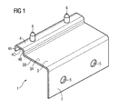
- FIG 1 shows a fixation element 1 enabled to be fixated to a cooking hob.
- fixation elements could be formed such that a fixation to a worktop is also possible.
- the fixation element 1 comprises a first section 2, a second section 3 and a third section 4.
- the first section 2 is arranged substantially rectangular to the second section 3 and the third section 4 adjoins directly to the second section 3.
- Second section 3 has an upper surface 3A and a lower surface 3B.
- the third section 4 is formed substantially U-shaped comprising a first vertical portion 4A, a second vertical portion 4B and a horizontal portion 4C.
- Two first fixation components 6, formed as pins, are arranged on an upper surface of the horizontal portion 4C extending in an upward direction.
- the pins can be formed cylindrically and can be formed conically at their ends which are arranged oppositely to the horizontal portion of the third section 4C. It is also possible to provide only one pin or more than two pins per fixation element.
- screw holes 5 or bore holes or recesses are provided in the first section 2 which can be used to fasten the fixation element to the cooking hob or to the worktop 7.
- FIG 2 shows a fixation element 1 in a mounted state.
- the fixation element 1 is arranged to support a cooking hob on a worktop 7.
- the cooking hob comprises a cooking hob plate 9 and a cooking hob housing 10. Usually such cooking hobs are arranged within a cutout of a worktop 7.
- the cooking hob plate 9 can be made of a glass ceramic plate or of another usual material.
- heating elements such as induction heating elements or electric resistance heating elements can be arranged below the cooking hob plate 9.
- the fixation element 1 is fastened or fixated or attached to the cooking hob housing 9, in particular to a housing side wall 12, by means of a fastening element 13 like a screw. Also other fastening elements like rivets or bolts or clip and/or snap connections can be used. Alternatively the fixation element 1 can be glued to the housing side wall 12.
- a surface 8 is formed by the worktop 7 whereupon the fixation element 1 is supported. More precisely, the second section 3 with its lower surface 3B bears on the surface 8 of the worktop 7. Consequently, the cooking hob housing 10 is supported by the fixation element 1.
- the cooking hob plate 9 which has an upper surface 9A and a lower surface 9B bears on the upper surface 3A of the second section 3 and is supported thereby indirectly on the worktop 7 or the surface 8 of the worktop 7, respectively.
- an assembly is established, comprising a cooking hob with a cooking hob housing 10, a cooking hob plate 9 and a fastening element 1 being supported on a worktop 9.
- an accessory 11 is supported by the cooking hob plate 9 and supported and fixated by the fixation element 1.
- the accessory might be a frying plate as shown but also frying pans or pots or other cookware are possible. Also other accessory parts, such as child safety parts, protective grids, storage elements or the like can be provided.
- an accessory 11 which is a frying plate has an upper surface 11A and a lower surface 11B, wherein the frying plate bears with its lower surface 11B on the upper surface 9A of the cooking hob plate 9.
- the frying plate can be made of an inductive material such that it can be heated up by operating the induction heating elements or, alternatively, independent from the used material, by operating resistance heating elements.
- the fixation element 1 bears on the worktop 7 by means of its third section 4.
- the substantially U-shaped third section 4 bears on the surface 8 of the worktop 7 by means of an end section of the first vertical portion 4A and an end section of the second vertical portion 4B.
- the fixation element 1 is supported upon the surface 8 of the worktop 7 by the second section 3 and the third section 4.
- the horizontal portion 4C which comprises the first fixation components 6 is arranged adjacent to the cooking hob plate 9, wherein the fixation element 1 and the first fixation components 6 are dimensioned such that the first fixation components 6 project over the upper surface 9A of the cooking hob plate 9 in a vertical direction.
- the accessory 11 to be arranged on the cooking hob plate 9 has second fixation components 16 which are formed as recesses or holes arranged on the lower side of the accessory 11 which correspond in dimensions and distance to the arrangement of the first fixation component 6, i.e. the pins provided by the fixation element 1.
- the recesses or holes are arranged on a boundary section 14 of the accessory 11 (here: a frying plate) such that the substantially most part of the lower surface 11B is in contact to the upper surface 9A of the cooking hob plate 9.
- the boundary section 14 is arranged above the third section 4 of the fixation element 1 and might comprise a step-like transition 15 which compensates a difference in height or different vertical levels of the upper surface 9A of the cooking hob plate 9 and the horizontal portion 4C of the third section 4 such that the boundary section 14 is in contact to the horizontal section 4C.
- the first fixation components 6, or the pins, respectively can engage into the recesses or holes and fixate the accessory 11 in a predetermined position relative to the cooking hob or on the cooking hob plate 9.
- fixation elements 1 can support the cooking hob on the worktop 7, wherein the position of the fixation element can be determined arbitrarily on one or several sides of the cooking hob or in corner regions of the cooking hob.
- the fixation elements can be positioned depending on the type of accessories and/or depending on the positions of the heating elements and the so defined cooking zones on the cooking hob plate 9.
- connection between accessory 11 and fixation element 1 can be secured by means of a locking mechanism. Thus, unintended displacement of the accessory is prevented.
- the fixation element 1 can be made of a sheet metal or made of a plastics material, manufactured e.g. in an injection moulding process.
- FIG 3 shows a cooking hob arranged within a cutout of a worktop 7 having a cooking hob plate 9.
- the cooking hob is supported on the worktop 7 by means of several fixation elements 1 which are not shown.
- the accessories 11 are secured in their positions relative to the cooking plate.
- One of the accessories 11 is a frying plate
- the other accessory 11 is a protection grid for preventing touch contact with the hot cooking hob plate, e.g. for the protection of children.
Landscapes
- Engineering & Computer Science (AREA)
- Chemical & Material Sciences (AREA)
- Combustion & Propulsion (AREA)
- Mechanical Engineering (AREA)
- General Engineering & Computer Science (AREA)
- Baking, Grill, Roasting (AREA)
Abstract
Fixation arrangement for a cooking hob, comprising:
- at least one fixation element (1), having:
- a first section (2) for fastening the fixation element (1) to a component of the cooking hob or to a worktop (7);
- a second section (3) for supporting the fixation element (1) upon a surface (8) of the worktop (7);
- a third section (4) having at least one first fixation component (6) being able to cooperate with at least one corresponding second fixation component (16) which is arranged on an accessory (11) provided for being used in association with the cooking hob, wherein the first fixation component (6) and the second fixation component (16) allow a detachably fixed positioning of the accessory (11) upon a cooking hob plate (9) of the cooking hob and/or relative to the cooking hob;
- at least one cooking hob plate (9) bearing on an upper surface (3A) of the second section (3) of the fixation element (1);
- at least one accessory (11) having a second fixation component (16) and being fixed, in particular detachably, in a position upon the cooking hob plate (9) and/or relative to the cooking hob by means of the first fixation component (6) of the third section (4) of the fixation element (1) cooperating with the second fixation component (16) of the accessory (11);
- at least one fixation element (1), having:
- a first section (2) for fastening the fixation element (1) to a component of the cooking hob or to a worktop (7);
- a second section (3) for supporting the fixation element (1) upon a surface (8) of the worktop (7);
- a third section (4) having at least one first fixation component (6) being able to cooperate with at least one corresponding second fixation component (16) which is arranged on an accessory (11) provided for being used in association with the cooking hob, wherein the first fixation component (6) and the second fixation component (16) allow a detachably fixed positioning of the accessory (11) upon a cooking hob plate (9) of the cooking hob and/or relative to the cooking hob;
- at least one cooking hob plate (9) bearing on an upper surface (3A) of the second section (3) of the fixation element (1);
- at least one accessory (11) having a second fixation component (16) and being fixed, in particular detachably, in a position upon the cooking hob plate (9) and/or relative to the cooking hob by means of the first fixation component (6) of the third section (4) of the fixation element (1) cooperating with the second fixation component (16) of the accessory (11);
Description
- The present invention relates to a fixation arrangement for a cooking hob.
-
GB 1 036 241 -
DE 93 10 768 U1 discloses a holder for pots, wherein a holder is vertically arranged and has two fixation teeth which are arranged horizontally. By means of the fixation teeth, a pot is fixated precisely upon the cooking zone. -
US 6 517 037 B1 describes a stove-top pan holding apparatus for providing safer conditions around stoves for children. The stove-top pan holding apparatus includes a pan holder support member being adapted to securely fastened to a stove; and also includes a pan holder being adjustably fastened to the pan holder support member for holding a handle of a pan upon the stove; and further includes fastening members for fastening the pan holder to the pan holder support member. - According to the prior art there are fixation arrangements known for cookware having several bulky components which comprise deficiencies in terms of easy handling or mounting.
- An object of the present invention is to enable a fixation of cookware upon a cooking hob which is easy and safely usable for an operator and which can be mounted and demounted quick and easy.
- A solution of these objects according to the invention is defined and characterized by
independent claim 1. The dependent claims refer to further embodiments of the present invention. - According to the present invention a fixation arrangement for a cooking hob comprises:
- at least one fixation element, having:
- a first section for fastening the fixation element to a component of the cooking hob or to a worktop;
- a second section for supporting the fixation element upon a surface of the worktop;
- a third section having at least one first fixation component being able to cooperate with at least one corresponding second fixation component which is arranged on an accessory provided for being used in association with the cooking hob, wherein the first fixation component and the second fixation component allow a detachably fixed positioning of the accessory upon a cooking hob plate of the cooking hob and/or relative to the cooking hob;
- a first section for fastening the fixation element to a component of the cooking hob or to a worktop;
- at least one cooking hob plate bearing on an upper surface of the second section of the fixation element;
- at least one accessory having a second fixation component and being fixed, in particular detachably, in a position upon the cooking hob plate and/or relative to the cooking hob by means of the first fixation component of the third section of the fixation element cooperating with the second fixation component of the accessory;
- Thus, a fixation arrangement is provided which enables an easy mounting, of the complete cooking hob to a worktop and offering the possibility to easily mount an accessory to the cooking hob or to an area nearby the cooking hob in a stable position and which provides the possibility to mount and demount the accessories in a quick and secure way. These features are combined in one component which improves the manufacturing and the mounting process for the cooking hob.
- According to a further embodiment of the invention the second section of the at least one fixation element has an upper surface and a lower surface, wherein the second section bears on a surface of the worktop with its lower surface and the cooking hob plate bears on the upper surface of the second section, in particular in such a way, that the fixation element is held at least partially in its position by the weight of the cooking hob plate.
- In such way a stable connection is established between the fixation element, the cooking hob and the worktop, wherein the cooking hob can be supported onto the worktop by means of the fixation element which provides at the same time the possibility to attach accessories to the cooking hob. Such an arrangement is very easy to mount.
- According to a further embodiment of the invention the third section of the at least one fixation element is formed substantially U-shaped, having a first vertical portion, a second vertical portion and a horizontal portion, wherein the horizontal portion comprises at least one first fixation component, in particular such that the first fixation component is arrangeable adjacent to the cooking hob plate and/or such that the first fixation component projects over an upper surface of the adjacent cooking hob plate.
- In such an embodiment a section exists for additionally supporting the fixation element on the worktop providing at the same time an arrangement of the first fixation component which is advantageously positioned and which can be cleaned easily. Thus, several possible positions for mounting the accessories can be chosen prior to the mounting of the cooking hob.
- According to a further embodiment of the invention the at least one first fixation component is a pin, in particular formed cylindrically with a conical end section oppositely to the horizontal portion of the third section and/or that the at least one corresponding second fixation component is a recess and/or a hole, in particular which corresponds in form, dimensions and distances to the arrangement of the at least one pin.
- The forming of the fixation components as pins and as corresponding recesses or holes within the accessory allows an easy manufacturing of the fixation element and the accessory and at the same time provides an easy assembling of a cooking hob comprising such a fixation element and an accessory combined with a precise and secure connection between these components.
- According to a further embodiment of the invention at least two pins are provided on at least one fixation element and that at least two corresponding recesses or holes are provided on one accessory.
- Thus, the accessory can be mounted to the cooking hob in a very secure way. At least in one horizontal plane, a form closure is established between the accessory and at least one fixation. Therefore a single fixation element is sufficient to secure the accessory safely to the cooking hob.
- According to a further embodiment of the invention the accessory is at least one of a frying plate, a frying pan, a cooking pot, a protection grid, a child safety device or a storage plate.
- It is adventageously possible to fasten cookware to the cooking hob. The cookware can be secured against displacement in a defined position over a cooking zone. Also it is possible to mount components which are not cookware, e.g. a safety device which improves the safety of the cooking hob, in particular the safety for children.
- According to a further embodiment of the invention the fixation between the fixation element and the accessory is secured by means of a detachable locking mechanism.
- Such a locking mechanism prevents unintended detaching of the cookware or other accessories and improves the safety of the cooking hob.
- In a further embodiment of the invention at least two corner sections of the cooking hob are each provided with at least one fixation element, cooperating with an accessory, in particular a protective accessory, that has a longitudinal extension from the one corner section of the cooking hob to the other corner section of the cooking hob.
- Thus, easy mounting of protective accessories is possible. Fixation elements can be provided on the cooking hob where it is necessary to mount an accessory.
- FIG 1
- is a perspective view of a fixation element according to the invention
- FIG 2
- is a sectional view of a cooking hob and an accessory being fixated by a fixation element
- FIG 3
- is a perspective view of a cooking hob and accessories being fixated by fixation elements
-
FIG 1 shows afixation element 1 enabled to be fixated to a cooking hob. Alternatively fixation elements could be formed such that a fixation to a worktop is also possible. - The
fixation element 1 comprises afirst section 2, a second section 3 and a third section 4. Thefirst section 2 is arranged substantially rectangular to the second section 3 and the third section 4 adjoins directly to the second section 3. Second section 3 has anupper surface 3A and alower surface 3B. The third section 4 is formed substantially U-shaped comprising a firstvertical portion 4A, a secondvertical portion 4B and ahorizontal portion 4C. - Two
first fixation components 6, formed as pins, are arranged on an upper surface of thehorizontal portion 4C extending in an upward direction. The pins can be formed cylindrically and can be formed conically at their ends which are arranged oppositely to the horizontal portion of thethird section 4C. It is also possible to provide only one pin or more than two pins per fixation element. - Furthermore two screw holes 5 or bore holes or recesses are provided in the
first section 2 which can be used to fasten the fixation element to the cooking hob or to theworktop 7. -
FIG 2 shows afixation element 1 in a mounted state. Thefixation element 1 is arranged to support a cooking hob on aworktop 7. The cooking hob comprises acooking hob plate 9 and acooking hob housing 10. Usually such cooking hobs are arranged within a cutout of aworktop 7. Thecooking hob plate 9 can be made of a glass ceramic plate or of another usual material. Within thecooking hob housing 10 heating elements (not shown) such as induction heating elements or electric resistance heating elements can be arranged below thecooking hob plate 9. - The
fixation element 1 is fastened or fixated or attached to thecooking hob housing 9, in particular to ahousing side wall 12, by means of afastening element 13 like a screw. Also other fastening elements like rivets or bolts or clip and/or snap connections can be used. Alternatively thefixation element 1 can be glued to thehousing side wall 12. - A
surface 8 is formed by theworktop 7 whereupon thefixation element 1 is supported. More precisely, the second section 3 with itslower surface 3B bears on thesurface 8 of theworktop 7. Consequently, thecooking hob housing 10 is supported by thefixation element 1. - Further, the
cooking hob plate 9 which has anupper surface 9A and alower surface 9B bears on theupper surface 3A of the second section 3 and is supported thereby indirectly on theworktop 7 or thesurface 8 of theworktop 7, respectively. Thus, an assembly is established, comprising a cooking hob with acooking hob housing 10, acooking hob plate 9 and afastening element 1 being supported on aworktop 9. - Furthermore an
accessory 11 is supported by thecooking hob plate 9 and supported and fixated by thefixation element 1. The accessory might be a frying plate as shown but also frying pans or pots or other cookware are possible. Also other accessory parts, such as child safety parts, protective grids, storage elements or the like can be provided. - According to
FIG 2 anaccessory 11 which is a frying plate has anupper surface 11A and alower surface 11B, wherein the frying plate bears with itslower surface 11B on theupper surface 9A of thecooking hob plate 9. The frying plate can be made of an inductive material such that it can be heated up by operating the induction heating elements or, alternatively, independent from the used material, by operating resistance heating elements. - Besides the second section 3, the
fixation element 1 bears on theworktop 7 by means of its third section 4. The substantially U-shaped third section 4 bears on thesurface 8 of theworktop 7 by means of an end section of the firstvertical portion 4A and an end section of the secondvertical portion 4B. Thus, thefixation element 1 is supported upon thesurface 8 of theworktop 7 by the second section 3 and the third section 4. - The
horizontal portion 4C which comprises thefirst fixation components 6 is arranged adjacent to thecooking hob plate 9, wherein thefixation element 1 and thefirst fixation components 6 are dimensioned such that thefirst fixation components 6 project over theupper surface 9A of thecooking hob plate 9 in a vertical direction. - The accessory 11 to be arranged on the
cooking hob plate 9 hassecond fixation components 16 which are formed as recesses or holes arranged on the lower side of the accessory 11 which correspond in dimensions and distance to the arrangement of thefirst fixation component 6, i.e. the pins provided by thefixation element 1. The recesses or holes are arranged on aboundary section 14 of the accessory 11 (here: a frying plate) such that the substantially most part of thelower surface 11B is in contact to theupper surface 9A of thecooking hob plate 9. Theboundary section 14 is arranged above the third section 4 of thefixation element 1 and might comprise a step-like transition 15 which compensates a difference in height or different vertical levels of theupper surface 9A of thecooking hob plate 9 and thehorizontal portion 4C of the third section 4 such that theboundary section 14 is in contact to thehorizontal section 4C. - When the
accessory 11 is attached to the cooking hob or thecooking hob plate 9, thefirst fixation components 6, or the pins, respectively, can engage into the recesses or holes and fixate the accessory 11 in a predetermined position relative to the cooking hob or on thecooking hob plate 9. -
Several fixation elements 1 can support the cooking hob on theworktop 7, wherein the position of the fixation element can be determined arbitrarily on one or several sides of the cooking hob or in corner regions of the cooking hob. The fixation elements can be positioned depending on the type of accessories and/or depending on the positions of the heating elements and the so defined cooking zones on thecooking hob plate 9. - The connection between
accessory 11 andfixation element 1 can be secured by means of a locking mechanism. Thus, unintended displacement of the accessory is prevented. - The
fixation element 1 can be made of a sheet metal or made of a plastics material, manufactured e.g. in an injection moulding process. -
FIG 3 shows a cooking hob arranged within a cutout of aworktop 7 having acooking hob plate 9. The cooking hob is supported on theworktop 7 by means ofseveral fixation elements 1 which are not shown. Theaccessories 11 are secured in their positions relative to the cooking plate. One of theaccessories 11 is a frying plate, theother accessory 11 is a protection grid for preventing touch contact with the hot cooking hob plate, e.g. for the protection of children. - It is also possible to prepare the cooking hob with fixation elements after the cooking hob is mounted to the worktop.
-
- 1
- Fixation element
- 2
- First section
- 3
- Second section
- 3A
- Upper surface of the second section
- 3B
- Lower surface of the second section
- 4
- Third section
- 4A
- First vertical portion of third section
- 4B
- Second vertical portion of third section
- 4C
- Horizontal portion of third section
- 5
- Screw hole
- 6
- First fixation component
- 7
- Worktop
- 8
- Surface of the worktop
- 9
- Cooking hob plate
- 9A
- Upper surface of cooking hob plate
- 9B
- Lower surface of cooking hob plate
- 10
- Cooking hob housing
- 11
- Accessory
- 11A
- Upper surface of accessory
- 11B
- Lower surface of accessory
- 12
- Housing side wall
- 13
- Fastening element
- 14
- Boundary section
- 15
- Step-like transition
- 16
- Second fixation component
Claims (8)
- Fixation arrangement for a cooking hob, comprising:- at least one fixation element (1), having:- a first section (2) for fastening the fixation element (1) to a component of the cooking hob or to a worktop (7);- a second section (3) for supporting the fixation element (1) upon a surface (8) of the worktop (7);- a third section (4) having at least one first fixation component (6) being able to cooperate with at least one corresponding second fixation component (16) which is arranged on an accessory (11) provided for being used in association with the cooking hob, wherein the first fixation component (6) and the second fixation component (16) allow a detachably fixed positioning of the accessory (11) upon a cooking hob plate (9) of the cooking hob and/or relative to the cooking hob;- at least one cooking hob plate (9) bearing on an upper surface (3A) of the second section (3) of the fixation element (1);- at least one accessory (11) having a second fixation component (16) and being fixed, in particular detachably, in a position upon the cooking hob plate (9) and/or relative to the cooking hob by means of the first fixation component (6) of the third section (4) of the fixation element (1) cooperating with the second fixation component (16) of the accessory (11);
- Fixation arrangement according to claim 1, characterized in that the second section (3) of the at least one fixation element (1) has an upper surface (3A) and a lower surface (3B), wherein the second section (3) bears on a surface (8) of the worktop (7) with its lower surface (3B) and the cooking hob plate (9) bears on the upper surface (3A) of the second section (3), in particular in such a way, that the fixation element (1) is held at least partially in its position by the weight of the cooking hob plate (9).
- Fixation arrangement according to one of the preceding claims, characterized in that the third section (4) of the at least one fixation element (1) is formed substantially U-shaped, having a first vertical portion (4A), a second vertical portion (4B) and a horizontal portion (4C), wherein the horizontal portion (4C) comprises at least one first fixation component (6), in particular such that the first fixation component (6) is arrangeable adjacent to the cooking hob plate (6) and/or such that the first fixation component (6) projects over an upper surface (9A) of the adjacent cooking hob plate (9).
- Fixation arrangement according to one of the preceding claims, characterized in that the at least one first fixation component (6) is a pin, in particular formed cylindrically with a conical end section oppositely to the horizontal portion (4C) of the third section (4) and/or that the at least one corresponding second fixation component (16) is a recess and/or a hole, in particular which corresponds in form, dimensions and distances to the arrangement of the at least one pin.
- Fixation arrangement according to one of the preceding claims, characterized in that at least two pins are provided on at least one fixation element (1) and that at least two corresponding recesses or holes are provided on one accessory (11).
- Fixation arrangement according to one of the preceding claims, characterized in that the accessory (11) is at least one of a frying plate, a frying pan, a cooking pot, a protection grid, a child safety device or a storage plate.
- Fixation arrangement according to one of the preceding claims, characterized in that the fixation between the fixation element (1) and the accessory (11) is secured by means of a detachable locking mechanism.
- Fixation arrangement according to one of the preceding claims, characterized in that at least two corner sections of the cooking hob are each provided with at least one fixation element (1), cooperating with an accessory (11), in particular a protective accessory, that has a longitudinal extension from the one corner section of the cooking hob to the other corner section of the cooking hob.
Priority Applications (1)
| Application Number | Priority Date | Filing Date | Title |
|---|---|---|---|
| EP11004010A EP2525154A1 (en) | 2011-05-14 | 2011-05-14 | Fixation arrangement for a cooking hob |
Applications Claiming Priority (1)
| Application Number | Priority Date | Filing Date | Title |
|---|---|---|---|
| EP11004010A EP2525154A1 (en) | 2011-05-14 | 2011-05-14 | Fixation arrangement for a cooking hob |
Publications (1)
| Publication Number | Publication Date |
|---|---|
| EP2525154A1 true EP2525154A1 (en) | 2012-11-21 |
Family
ID=44558282
Family Applications (1)
| Application Number | Title | Priority Date | Filing Date |
|---|---|---|---|
| EP11004010A Withdrawn EP2525154A1 (en) | 2011-05-14 | 2011-05-14 | Fixation arrangement for a cooking hob |
Country Status (1)
| Country | Link |
|---|---|
| EP (1) | EP2525154A1 (en) |
Citations (7)
| Publication number | Priority date | Publication date | Assignee | Title |
|---|---|---|---|---|
| DE1139956B (en) * | 1955-10-07 | 1962-11-22 | Lars Eric Friberg | Protective device on gas or electric stoves |
| GB1036241A (en) | 1962-01-22 | 1966-07-13 | Oatley Technical Dev | Safety device against the overturning of pans on cooker hobs |
| DE9310768U1 (en) | 1993-07-19 | 1993-09-30 | Muck, Rolf, 66849 Landstuhl | Pot hanger |
| DE9315414U1 (en) * | 1993-10-12 | 1993-12-23 | Sichert, Harald, Dipl.-Ing. (FH), 91564 Neuendettelsau | Pot holder for fixing cooking and roasting pots and frying pans on cooktops / hobs |
| EP0641975A1 (en) * | 1993-09-06 | 1995-03-08 | Seb S.A. | Liquid collector for cooking hobs |
| US5575445A (en) * | 1994-02-14 | 1996-11-19 | Kozdas; Anthony B. | Stove-top aid |
| US6517037B1 (en) | 2001-03-30 | 2003-02-11 | Ramiro A. Munoz | Stove-top pan holding apparatus |
-
2011
- 2011-05-14 EP EP11004010A patent/EP2525154A1/en not_active Withdrawn
Patent Citations (7)
| Publication number | Priority date | Publication date | Assignee | Title |
|---|---|---|---|---|
| DE1139956B (en) * | 1955-10-07 | 1962-11-22 | Lars Eric Friberg | Protective device on gas or electric stoves |
| GB1036241A (en) | 1962-01-22 | 1966-07-13 | Oatley Technical Dev | Safety device against the overturning of pans on cooker hobs |
| DE9310768U1 (en) | 1993-07-19 | 1993-09-30 | Muck, Rolf, 66849 Landstuhl | Pot hanger |
| EP0641975A1 (en) * | 1993-09-06 | 1995-03-08 | Seb S.A. | Liquid collector for cooking hobs |
| DE9315414U1 (en) * | 1993-10-12 | 1993-12-23 | Sichert, Harald, Dipl.-Ing. (FH), 91564 Neuendettelsau | Pot holder for fixing cooking and roasting pots and frying pans on cooktops / hobs |
| US5575445A (en) * | 1994-02-14 | 1996-11-19 | Kozdas; Anthony B. | Stove-top aid |
| US6517037B1 (en) | 2001-03-30 | 2003-02-11 | Ramiro A. Munoz | Stove-top pan holding apparatus |
Similar Documents
| Publication | Publication Date | Title |
|---|---|---|
| EP2510844B1 (en) | Grill and / or frying plate for the use on cooking hobs | |
| US10281157B2 (en) | Gas cooktop with integrated wok | |
| US11187416B2 (en) | Gas cooktop and grate for the gas cooktop | |
| EP2589879B1 (en) | Gas burner assembly, gas cooking hob and gas burner appliance | |
| KR101667013B1 (en) | Cooking vessel for induction range | |
| WO2018024558A1 (en) | Cooking appliance with improved side wire racks | |
| CN104620054A (en) | Improved rack for holding cookware on a cooktop | |
| EP2501997B1 (en) | Cooking hob | |
| US10465913B2 (en) | Burner module provided with heat shield and bush, cooker or hob provided therewith and method for manufacture thereof | |
| WO2015032673A2 (en) | A cooker comprising a burner housing | |
| EP2798276B1 (en) | A cooker | |
| EP2938931B1 (en) | A cooker with pan support | |
| KR20140087944A (en) | Cooking device supporting apparatus | |
| CN101600380A (en) | Safety device for range surface | |
| EP2798275B1 (en) | A cooker | |
| KR20110010007U (en) | Covered Pot Handle | |
| EP2607789A2 (en) | A cooking top, in particular for household use | |
| WO2013097986A1 (en) | A cooker | |
| JPS597867Y2 (en) | electric cooker | |
| KR101284454B1 (en) | Grit of cooking vessel | |
| KR101240035B1 (en) | Satety shelf for kitchen utensil | |
| JPH031690Y2 (en) | ||
| KR20090000795U (en) | Large grill plate base for table roasters | |
| JP2014035159A (en) | Table cooking stove | |
| KR20130120583A (en) | Kitchen gas appliances equipped with temperature measurement sensor |
Legal Events
| Date | Code | Title | Description |
|---|---|---|---|
| PUAI | Public reference made under article 153(3) epc to a published international application that has entered the european phase |
Free format text: ORIGINAL CODE: 0009012 |
|
| AK | Designated contracting states |
Kind code of ref document: A1 Designated state(s): AL AT BE BG CH CY CZ DE DK EE ES FI FR GB GR HR HU IE IS IT LI LT LU LV MC MK MT NL NO PL PT RO RS SE SI SK SM TR |
|
| AX | Request for extension of the european patent |
Extension state: BA ME |
|
| 17P | Request for examination filed |
Effective date: 20130516 |
|
| STAA | Information on the status of an ep patent application or granted ep patent |
Free format text: STATUS: THE APPLICATION IS DEEMED TO BE WITHDRAWN |
|
| 18D | Application deemed to be withdrawn |
Effective date: 20141202 |