EP2525102A2 - Air volume adjustment device for air conditioner - Google Patents
Air volume adjustment device for air conditioner Download PDFInfo
- Publication number
- EP2525102A2 EP2525102A2 EP12168111A EP12168111A EP2525102A2 EP 2525102 A2 EP2525102 A2 EP 2525102A2 EP 12168111 A EP12168111 A EP 12168111A EP 12168111 A EP12168111 A EP 12168111A EP 2525102 A2 EP2525102 A2 EP 2525102A2
- Authority
- EP
- European Patent Office
- Prior art keywords
- static pressure
- rotational speed
- air volume
- motor
- fan motor
- Prior art date
- Legal status (The legal status is an assumption and is not a legal conclusion. Google has not performed a legal analysis and makes no representation as to the accuracy of the status listed.)
- Withdrawn
Links
Images

Classifications
-
- F—MECHANICAL ENGINEERING; LIGHTING; HEATING; WEAPONS; BLASTING
- F04—POSITIVE - DISPLACEMENT MACHINES FOR LIQUIDS; PUMPS FOR LIQUIDS OR ELASTIC FLUIDS
- F04D—NON-POSITIVE-DISPLACEMENT PUMPS
- F04D27/00—Control, e.g. regulation, of pumps, pumping installations or pumping systems specially adapted for elastic fluids
- F04D27/004—Control, e.g. regulation, of pumps, pumping installations or pumping systems specially adapted for elastic fluids by varying driving speed
-
- F—MECHANICAL ENGINEERING; LIGHTING; HEATING; WEAPONS; BLASTING
- F24—HEATING; RANGES; VENTILATING
- F24F—AIR-CONDITIONING; AIR-HUMIDIFICATION; VENTILATION; USE OF AIR CURRENTS FOR SCREENING
- F24F1/00—Room units for air-conditioning, e.g. separate or self-contained units or units receiving primary air from a central station
- F24F1/0007—Indoor units, e.g. fan coil units
- F24F1/0018—Indoor units, e.g. fan coil units characterised by fans
-
- F—MECHANICAL ENGINEERING; LIGHTING; HEATING; WEAPONS; BLASTING
- F24—HEATING; RANGES; VENTILATING
- F24F—AIR-CONDITIONING; AIR-HUMIDIFICATION; VENTILATION; USE OF AIR CURRENTS FOR SCREENING
- F24F1/00—Room units for air-conditioning, e.g. separate or self-contained units or units receiving primary air from a central station
- F24F1/0007—Indoor units, e.g. fan coil units
- F24F1/0043—Indoor units, e.g. fan coil units characterised by mounting arrangements
- F24F1/0047—Indoor units, e.g. fan coil units characterised by mounting arrangements mounted in the ceiling or at the ceiling
-
- F—MECHANICAL ENGINEERING; LIGHTING; HEATING; WEAPONS; BLASTING
- F24—HEATING; RANGES; VENTILATING
- F24F—AIR-CONDITIONING; AIR-HUMIDIFICATION; VENTILATION; USE OF AIR CURRENTS FOR SCREENING
- F24F1/00—Room units for air-conditioning, e.g. separate or self-contained units or units receiving primary air from a central station
- F24F1/0007—Indoor units, e.g. fan coil units
- F24F1/0083—Indoor units, e.g. fan coil units with dehumidification means
-
- F—MECHANICAL ENGINEERING; LIGHTING; HEATING; WEAPONS; BLASTING
- F24—HEATING; RANGES; VENTILATING
- F24F—AIR-CONDITIONING; AIR-HUMIDIFICATION; VENTILATION; USE OF AIR CURRENTS FOR SCREENING
- F24F11/00—Control or safety arrangements
- F24F11/70—Control systems characterised by their outputs; Constructional details thereof
- F24F11/72—Control systems characterised by their outputs; Constructional details thereof for controlling the supply of treated air, e.g. its pressure
- F24F11/74—Control systems characterised by their outputs; Constructional details thereof for controlling the supply of treated air, e.g. its pressure for controlling air flow rate or air velocity
- F24F11/77—Control systems characterised by their outputs; Constructional details thereof for controlling the supply of treated air, e.g. its pressure for controlling air flow rate or air velocity by controlling the speed of ventilators
-
- Y—GENERAL TAGGING OF NEW TECHNOLOGICAL DEVELOPMENTS; GENERAL TAGGING OF CROSS-SECTIONAL TECHNOLOGIES SPANNING OVER SEVERAL SECTIONS OF THE IPC; TECHNICAL SUBJECTS COVERED BY FORMER USPC CROSS-REFERENCE ART COLLECTIONS [XRACs] AND DIGESTS
- Y02—TECHNOLOGIES OR APPLICATIONS FOR MITIGATION OR ADAPTATION AGAINST CLIMATE CHANGE
- Y02B—CLIMATE CHANGE MITIGATION TECHNOLOGIES RELATED TO BUILDINGS, e.g. HOUSING, HOUSE APPLIANCES OR RELATED END-USER APPLICATIONS
- Y02B30/00—Energy efficient heating, ventilation or air conditioning [HVAC]
- Y02B30/70—Efficient control or regulation technologies, e.g. for control of refrigerant flow, motor or heating
Definitions
- the present invention relates to an air volume adjustment device for an air conditioner of a type that blows air whose temperature is controlled into a room through a duct connected to a unit body.
- AC motors have been adopted as fan motors in a duct-type air conditioner which is configured to blow air into a room through a duct disposed, for example, inside of the ceiling, and in which the temperature of the air has been controlled in a unit body having a heat exchanger and a fan housed therein.
- the stack loss varies according to the length, diameter, shape, or the like, of the duct. Therefore, there has been no way to grasp an external static pressure determined thereby. Accordingly, in old buildings or other constructions where ducts are appropriated as-is in installation of an air conditioner, if the external static pressure is large, the air volume of the air conditioner is reduced, resulting in performance decline. On the other hand, where the external static pressure is small, the air volume becomes too large, thereby degrading the draft. These have been problems.
- PTL 1 discloses a DC fan motor for constant air volume control for a ventilator that can drive with an instructed constant air volume even with varied pressure losses depending on the length, diameter, shape, or the like, of a duct, while being able to control the constant air volume without providing a special sensor or the like to detect the air volume.
- the DC fan motor has storage means for storing rotational speeds corresponding to voltages applied to a DC motor for providing an air volume instructed by air volume instruction means that instructs the air volume, and voltage control means that compares the actual rotational speed of the DC motor detected by the rotational speed detection means and a prescribed rotational speed stored in the storage means and corresponding to both of the present instructed air volume and the applied voltage, and controls the voltage applied to the DC motor so that the actual rotational speeds becomes equal to the prescribed rotational speed.
- the device disclosed in PTL 1 starts driving by applying voltage set in advance to the DC motor; compares the actual rotational speed Na of the motor detected by the rotational speed detection means with a prescribed rotational speed Nma corresponding to both of the present instructed air volume Qm and the applied voltage Va, stored in the storage means; and repeatedly drives by increasing and decreasing the voltage applied to the motor until the actual rotational speed Na becomes equal to the prescribed rotational speed Nma.
- the device achieves the instructed air volume, thereby making it possible to perform driving with a constant air volume.
- the adjustment by the device takes a time, and because the device merely performs the control of the applied voltage such that the actual rotational speed becomes equal to the prescribed rotational speed, there have been problems in absorbing variations in the voltage of the control circuit component, a power supply voltage, and a motor instruction voltage, and in accurately adjusting to a constant air volume, or the like.
- the present invention is made in view of the above-described circumstances, and an object of the present invention is to provide an air volume adjustment device for an air conditioner that can rapidly and accurately adjust the air volume by determining, by the unit itself, the external static pressure that varies according to the length, diameter, shape, or the like, of the duct so as to achieve a rated air volume with such an external static pressure.
- an air volume adjustment device for an air conditioner of the present invention is an air volume adjustment device for an air conditioner of a type in which a heat exchanger and a DC fan motor are housed in a unit body and air whose temperature is controlled in the heat exchanger is blown into a room through an air outlet duct connected to the unit body, the air volume adjustment device including: an air volume adjustment circuit configured to: drive the DC fan motor at two predefined rotational speeds; read, while driving, a motor output value output from a motor control circuit side to the DC fan motor; determine an external static pressure from a difference between motor output values at the two rotational speeds, and set a rotational speed of the DC fan motor so that a rated air volume is achieved based on the external static pressure and from a rotational speed table for each static pressure setting.
- the device has an air volume adjustment circuit configured to: drive the DC fan motor at two predefined rotational speeds; read, while driving, a motor output value output from a motor control circuit side to a DC fan motor; determine an external static pressure from a difference between motor output values at the two rotational speeds, and set a rotational speed of the DC fan motor so that a rated air volume is achieved based on the external static pressure and from a rotational speed table for each static pressure setting.
- the air volume adjustment circuit includes: driving instruction means that drives the DC fan motor at two predefined rotational speeds A and B; calculation means that reads the motor output value output from the motor control circuit to the DC fan motor according to the instruction from the driving instruction means and calculates a difference between the motor output values; determination means that determines an external static pressure based on a determination table and from the difference between the motor output values calculated by the calculation means; rotational speed setting means that sets the rotational speed of the DC fan motor based on the external static pressure and from the rotational speed table for each static pressure setting so that the rated air volume is achieved; and storage means that stores data including the determination table and the rotational speed table for each static pressure setting.
- the air volume adjustment circuit includes: driving instruction means that drives the DC fan motor at two predefined rotational speeds A and B; calculation means that reads the motor output value output from the motor control circuit to the DC fan motor according to the instruction from the driving instruction means and calculates a difference between the motor output values; determination means that determines an external static pressure based on a determination table and from the difference between the motor output values calculated by the calculation means; rotational speed setting means that sets the rotational speed of the DC fan motor based on the external static pressure and from the rotational speed table for each static pressure setting so that the rated air volume is achieved; and storage means that stores data including the determination table and the rotational speed table for each static pressure setting.
- the air conditioner it is possible, after the installation of the air conditioner, to drive the DC fan motor with two predefined rotational speeds A and B according to the instruction by the driving instruction means, read the actual motor output value, and calculate the difference between the output values by the calculation means, and determine an external static pressure from the value by the determination means, and set the rotational speed of the DC fan motor by the rotational speed setting means based on the external static pressure and from the rotational speed table for each static pressure setting so that the rated air volume is achieved. Therefore, the external static pressure that varies according to the length, diameter, shape, or the like, of the duct can be determined by the unit itself, and the air volume can rapidly and accurately be adjusted so that the rated air volume can be achieved with the external static pressure.
- the output value output from the motor control circuit to the DC fan motor is determined to be rotational speed instruction voltages VspA and VspB
- the calculation means reads the rotational speed instruction voltages VspA and VspB and calculates the difference ⁇ Vsp therebetween
- the determination means determines an external static pressure on a side of the air outlet duct based on ⁇ Vsp calculated by the calculation means
- the rotational speed setting means has a function to set the rotational speed of the DC fan motor based on the external static pressure and from the rotational speed table for each static pressure setting.
- the output value output from the motor control circuit to the DC fan motor is determined to be rotational speed instruction voltages VspA and VspB
- the calculation means reads the rotational speed instruction voltages VspA and VspB and calculates the difference ⁇ Vsp therebetween
- the determination means determines an external static pressure based on ⁇ Vsp calculated by the calculation means
- the rotational speed setting means has a function to set the rotational speed of the DC fan motor based on the external static pressure and from the rotational speed table for each static pressure setting.
- the present invention it is possible to rapidly adjust the air volume by determining an external static pressure by the unit itself from a difference between actual motor output values of the DC fan motor driven with two predefined rotational speeds after the installation of the air conditioner, and setting the rotational speed of the DC fan motor based on the external static pressure and from the rotational speed table for each static pressure setting so that the rated air volume is achieved. Accordingly, it is possible to perform driving while securing the instructed air volume of the air conditioner, and prevent performance decline due to the reduction in the air volume where the external static pressure is high and the draft caused by increase in the air volume where the external static pressure is low. Moreover, since the external static pressure is determined from the difference between motor output values acquired at two rotational speeds, variations in the voltage of the circuit component at the controller side, power supply voltage, the motor output value, or the like, can be absorbed to accurately adjust the air volume.
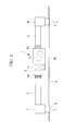
- Figure 1 is a schematic side-view showing one exemplary installation state of a duct-type air conditioner according to one embodiment of the present invention
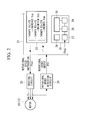
- Figure 2 is a control circuit diagram of the DC fan motor of the duct-type air conditioner shown in Figure 1 ;
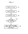
- Figure 3 is a flowchart showing the control at a time of air volume adjustment according to the control circuit diagram of the DC fan motor shown in Figure 2 ;
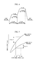
- Figure 4 is a chart showing timings of a revolution instruction to the DC fan motor at the time of air volume adjustment
- Figure 5 is a graph showing a relation among the rotational speed of the DC fan motor, the motor output (Vsp) and the static pressure at the time of air volume adjustment;
- ⁇ Fig. 6 ⁇ Figure 6 shows one example of a determination table for selecting a static pressure setting No from the difference of the motor outputs (Vsp) at the time of air volume adjustment;
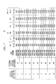
- Figure 7 shows one example of a table of rotational speed for each static pressure setting employed for setting the rotational speed of the DC fan motor at the time of air volume adjustment.
- Figure 1 is a schematic side-view showing one exemplary installation state of a duct-type air conditioner according to one embodiment of the present invention
- Figure 2 shows a control circuit diagram of the DC fan motor.
- the present embodiment illustrates a duct-type air conditioner embedded in the ceiling as one example of the duct-type air conditioner.
- a unit body 2 of this duct-type air conditioner 1, as shown in Figure 1 is configured to be installed so as to be hanged in the ceiling via a plurality of hanging bolts provided in the vertical direction on a beam or the like of the building. Drawings for an outside unit to be installed outside are omitted.
- This duct-type air conditioner 1 is configured to blow the air into a room through an air outlet duct 6, an air outlet unit 7 and an air outlet grille 8, or other elements, after cooling or heating in-room air sucked from the inside of a room through an air inlet grille 3, a noise reduction chamber 4 and an air inlet duct 5, by exchanging heat with a refrigerant.
- the length, diameter, shape, or the like, of the air outlet duct 6 are variously changed depending on the location of the air outlet unit 7, or other factors.
- the ceiling face 9 is provided with an access hole 10 to check or perform maintenance of the unit body 2 of the duct-type air conditioner 1.
- the unit body 2 is configured to have a box shape, and includes thereinside an inside heat exchanger 11 that exchanges heat between the refrigerant and the in-room air, a DC fan motor 12 including a plurality of pairs of sirocco fans that circulate in-room air and a DC motor, a drain pan that receives drain water generated in the inside heat exchanger 11, a drain pump that discharges drain water having accumulated in a drain pan to the outside and so on (drawings for the drain pan and the drain pump are omitted). Further, on the outside of the device, an air inlet 13 and an air outlet 14 to which the air inlet duct 5 and the air outlet duct 6 are connected are provided on the front and rear sides.
- the DC fan motor 12 is configured such that the DC motor 20 is driven to revolve through a driving circuit 23 based on a motor output value output from the motor control circuit 22 of the controller (control substrate) 21 (for example, rotational speed instruction voltage Vsp), and the rotational speed is detected by a rotational speed detection circuit 24, and by feeding back the output FG from the rotational speed detection circuit 24 to the motor control circuit 22 of the controller 21, the target value (target FG) and the rotational speed output FG are compared to adjust the output value (rotational speed instruction voltage Vsp) to the DC motor 20 so that the rotational speed of the DC fan motor 12 becomes the target FG.
- a motor output value output from the motor control circuit 22 of the controller (control substrate) 21 for example, rotational speed instruction voltage Vsp
- Vsp rotational speed instruction voltage
- an air volume adjustment circuit 25 that adjusts the air volume (rotational speed) of the DC fan motor 12 corresponding to the external static pressure determined according to a pressure loss that varies mainly according to the length, diameter, the shape, or the like, of the air outlet duct 6, is provided so that rated air volume is achieved even when the external static pressure varies.
- the air volume adjustment circuit 25 first drives the DC fan motor 12 according to an instruction from the driving instruction means 26 in step S1 for several minutes with rotational speed A rpm set in advance, as shown in Figure 3 .
- the air volume adjustment circuit 25 drives the DC fan motor 12 with the rotational speed B rpm set in advance for several minutes.
- the DC fan motor 12 is driven in a perflation mode.
- Figure 4 shows a timing chart of this case, in which a fan motor Duty is sampled for 1 minute before completion of driving of the motor initiated according to respective instructions to drive the motor with A rpm and B rpm.
- the fan motor Duty at the two respective rotational speeds A rpm and B rpm is sampled by reading ⁇ VspA and ⁇ VspB based on the graph showing the relation among the rotational speed (rpm) of the DC fan motor 12, the motor output (Vsp) and the static pressure, as shown in Figure 5 .
- step S3 when the difference ⁇ Vsp between the motor output values ( ⁇ VspA and ⁇ VspB) is calculated, the process proceeds to step S4.
- the determination means 28 uses an calculation value ⁇ Vsp calculated by the calculation means 27, to determine the external static pressure of the air conditioner 1, based on the determination table for the static pressure setting No according to the motor output difference ( ⁇ Vsp) for each type of the device, for example shown in Figure 6 and stored in the storage means 30, and by selecting the static pressure setting No therefrom.
- step S4 the static pressure setting No is selected and the external static pressure is determined
- the process proceeds to step S5.
- the rotational speed setting means 29 sets the rotational speed of the DC fan motor 12 so that the rated air volume is achieved from the rotational speed table 32 for each static pressure setting with a selected static pressure No.
- the static pressure setting No. 3 is selected and the external static pressure is determined as 30Pa
- the DC fan motor 12 is to be revolved at 1030 rpm by Uhi2 tap.
- the instructed air volume is 9 m 3 /min
- the DC fan motor 12 is revolved by the Me tap at 760 rpm.
- the present embodiment achieves the following working effect.
- the DC fan motor 12 is driven, and the in-room air is sucked through the air inlet grille 3, the noise reduction chamber 4 and the air inlet duct 5 into the unit body 2.
- the air is subjected to heat exchange in the inside heat exchanger 11 with the refrigerant delivered from the outside unit, and cooled or heated. Then, the air is blown into a room through the air outlet duct 6, the air outlet unit 7 and the air outlet grille 8 for air-conditioning the inside of the room.
- the DC fan motor 12 is driven with two predefined rotational speeds A rpm and B rpm by the air volume adjustment circuit 25; while driving, the motor output values, in other words, the rotational speed instruction voltages VspA, VspB, output from the motor control circuit 22 side to the DC fan motor, are read; and by the unit itself determines the external static pressure from the difference ⁇ Vsp between the motor output values VspA and VspB; and the rotational speed of the DC fan motor 12 is set so that the rated air volume is achieved based on the external static pressure and according to the rotational speed table 31 for each static pressure setting.
- the DC fan motor 12 is driven with two predefined rotational speeds A rpm and B rpm by the instruction from the driving instruction means 26, and the rotational speed instruction voltages VspA, VspB, which are the output values from the controller 21 to the DC fan motor 12 at that time, are read, and the difference ⁇ Vsp between the output values are calculated by the calculation means 27, and the external static pressure is determined based on the determination table 31 and from the value ⁇ Vsp by the determination means 28, and by setting the rotational speed of the DC fan motor 12 so as to achieve the rated air volume by the rotational speed setting means 29 and according to the rotational speed table 32 for each static pressure setting, based on the external static pressure. This allows rapidly performing the air volume adjustment.
- the present embodiment it is possible to drive the air conditioner 1 with the instructed air volume being secured and prevent performance decline caused by the reduction in the air volume where the external static pressure is high and a draft caused by increase in the air volume where the external static pressure is low.
- the present embodiment is configured so that the external static pressure is determined from the difference ⁇ Vsp between the motor output values VspA, VspB at the two rotational speeds A rpm and B rpm, it is possible to absorb variations in the voltage of the circuit components, the power supply voltage, the motor output value, or the like, at the controller 21 side, thereby allowing accurately adjusting the air volume.
- the present embodiment is configured as follows: the output values output from the motor control circuit 22 to the DC fan motor 21 are determined to be the rotational speed instruction voltages VspA and VspB; the calculation means 27 reads the rotational speed instruction voltages VspA and VspB and calculates the difference ⁇ Vsp therebetween; the determination means 28 determines the external static pressure from ⁇ Vsp calculated by the calculation means 27 based on the determination table 31; the rotational speed setting means 29 has a function to set the rotational speed of the DC fan motor 12 from the rotational speed table 32 for each static pressure setting based on the external static pressure.
- the present invention is not limited to that described in the above-described embodiment, and can be appropriately modified within an extent not to depart from the gist of the present invention.
- a sirocco fan is used as a DC fan motor 12
- the DC fan motor 12 is not limited to this.
- the air outlet duct 6, the air outlet unit 7 and the air outlet grille 8, and the like can have any shape or structure, and not specified in particular ones.
- the present invention is applicable also to an air conditioner 1 in which an air inlet is provided on the lower face of the unit body 2, and the in-room air is directly sucked into the unit body 2 from the air inlet.
- the output value (instruction value) output from the motor control circuit 22 to the DC fan motor 12 is determined as the rotational speed instruction voltage Vsp, the rotational speed instruction voltage Vsp should not necessarily be adopted, and any other instruction values may also be used.
Abstract
Description
- The present invention relates to an air volume adjustment device for an air conditioner of a type that blows air whose temperature is controlled into a room through a duct connected to a unit body.
- AC motors have been adopted as fan motors in a duct-type air conditioner which is configured to blow air into a room through a duct disposed, for example, inside of the ceiling, and in which the temperature of the air has been controlled in a unit body having a heat exchanger and a fan housed therein. In this case, since the fan is driven with a constant power, the stack loss varies according to the length, diameter, shape, or the like, of the duct. Therefore, there has been no way to grasp an external static pressure determined thereby. Accordingly, in old buildings or other constructions where ducts are appropriated as-is in installation of an air conditioner, if the external static pressure is large, the air volume of the air conditioner is reduced, resulting in performance decline. On the other hand, where the external static pressure is small, the air volume becomes too large, thereby degrading the draft. These have been problems.
- Then,
PTL 1 discloses a DC fan motor for constant air volume control for a ventilator that can drive with an instructed constant air volume even with varied pressure losses depending on the length, diameter, shape, or the like, of a duct, while being able to control the constant air volume without providing a special sensor or the like to detect the air volume. - The DC fan motor has storage means for storing rotational speeds corresponding to voltages applied to a DC motor for providing an air volume instructed by air volume instruction means that instructs the air volume, and voltage control means that compares the actual rotational speed of the DC motor detected by the rotational speed detection means and a prescribed rotational speed stored in the storage means and corresponding to both of the present instructed air volume and the applied voltage, and controls the voltage applied to the DC motor so that the actual rotational speeds becomes equal to the prescribed rotational speed.
- {PTL 1}
Publication of Japanese Patent No.3012721 - However, the device disclosed in
PTL 1 starts driving by applying voltage set in advance to the DC motor; compares the actual rotational speed Na of the motor detected by the rotational speed detection means with a prescribed rotational speed Nma corresponding to both of the present instructed air volume Qm and the applied voltage Va, stored in the storage means; and repeatedly drives by increasing and decreasing the voltage applied to the motor until the actual rotational speed Na becomes equal to the prescribed rotational speed Nma. By performing the above, the device achieves the instructed air volume, thereby making it possible to perform driving with a constant air volume. Due to the above procedure, the adjustment by the device takes a time, and because the device merely performs the control of the applied voltage such that the actual rotational speed becomes equal to the prescribed rotational speed, there have been problems in absorbing variations in the voltage of the control circuit component, a power supply voltage, and a motor instruction voltage, and in accurately adjusting to a constant air volume, or the like. - The present invention is made in view of the above-described circumstances, and an object of the present invention is to provide an air volume adjustment device for an air conditioner that can rapidly and accurately adjust the air volume by determining, by the unit itself, the external static pressure that varies according to the length, diameter, shape, or the like, of the duct so as to achieve a rated air volume with such an external static pressure.
- In order to solve the above-described problems, an air volume adjustment device for an air conditioner of the present invention adopts solutions stated in the following.
That is, an air volume adjustment device for an air conditioner according to one aspect of the present invention is an air volume adjustment device for an air conditioner of a type in which a heat exchanger and a DC fan motor are housed in a unit body and air whose temperature is controlled in the heat exchanger is blown into a room through an air outlet duct connected to the unit body, the air volume adjustment device including: an air volume adjustment circuit configured to: drive the DC fan motor at two predefined rotational speeds; read, while driving, a motor output value output from a motor control circuit side to the DC fan motor; determine an external static pressure from a difference between motor output values at the two rotational speeds, and set a rotational speed of the DC fan motor so that a rated air volume is achieved based on the external static pressure and from a rotational speed table for each static pressure setting. - According to the above-described aspect, the device has an air volume adjustment circuit configured to: drive the DC fan motor at two predefined rotational speeds; read, while driving, a motor output value output from a motor control circuit side to a DC fan motor; determine an external static pressure from a difference between motor output values at the two rotational speeds, and set a rotational speed of the DC fan motor so that a rated air volume is achieved based on the external static pressure and from a rotational speed table for each static pressure setting. Therefore, it is possible to rapidly adjust the air volume by determining an external static pressure by the unit itself from a difference between motor output values with the DC fan motor driven at two predefined rotational speeds after the installation of the air conditioner, and setting the rotational speed of the DC fan motor based on the external static pressure and the rotational speed table for each static pressure setting so that the rated air volume is achieved. Accordingly, it is possible to perform driving while securing the instructed air volume of the air conditioner, and prevent performance decline due to the reduction in the air volume where the external static pressure is high and the draft caused by increase in the air volume where the external static pressure is low. Moreover, since the external static pressure is determined from the difference between motor output values at the two rotational speeds, variations in the voltage of the circuit component at the controller side, power supply voltage or the motor output value can be absorbed to accurately adjust the air volume.
- Further, in the air volume adjustment device for an air conditioner according to the above-described aspect, the air volume adjustment circuit includes: driving instruction means that drives the DC fan motor at two predefined rotational speeds A and B; calculation means that reads the motor output value output from the motor control circuit to the DC fan motor according to the instruction from the driving instruction means and calculates a difference between the motor output values; determination means that determines an external static pressure based on a determination table and from the difference between the motor output values calculated by the calculation means; rotational speed setting means that sets the rotational speed of the DC fan motor based on the external static pressure and from the rotational speed table for each static pressure setting so that the rated air volume is achieved; and storage means that stores data including the determination table and the rotational speed table for each static pressure setting.
- According to the above-described aspect, the air volume adjustment circuit includes: driving instruction means that drives the DC fan motor at two predefined rotational speeds A and B; calculation means that reads the motor output value output from the motor control circuit to the DC fan motor according to the instruction from the driving instruction means and calculates a difference between the motor output values; determination means that determines an external static pressure based on a determination table and from the difference between the motor output values calculated by the calculation means; rotational speed setting means that sets the rotational speed of the DC fan motor based on the external static pressure and from the rotational speed table for each static pressure setting so that the rated air volume is achieved; and storage means that stores data including the determination table and the rotational speed table for each static pressure setting. Therefore, it is possible, after the installation of the air conditioner, to drive the DC fan motor with two predefined rotational speeds A and B according to the instruction by the driving instruction means, read the actual motor output value, and calculate the difference between the output values by the calculation means, and determine an external static pressure from the value by the determination means, and set the rotational speed of the DC fan motor by the rotational speed setting means based on the external static pressure and from the rotational speed table for each static pressure setting so that the rated air volume is achieved. Therefore, the external static pressure that varies according to the length, diameter, shape, or the like, of the duct can be determined by the unit itself, and the air volume can rapidly and accurately be adjusted so that the rated air volume can be achieved with the external static pressure.
- Further, in the air volume adjustment device for an air conditioner of the above-described aspect, the output value output from the motor control circuit to the DC fan motor is determined to be rotational speed instruction voltages VspA and VspB, and the calculation means reads the rotational speed instruction voltages VspA and VspB and calculates the difference ΔVsp therebetween, and the determination means determines an external static pressure on a side of the air outlet duct based on ΔVsp calculated by the calculation means, and the rotational speed setting means has a function to set the rotational speed of the DC fan motor based on the external static pressure and from the rotational speed table for each static pressure setting.
- According to the above-described aspect, the output value output from the motor control circuit to the DC fan motor is determined to be rotational speed instruction voltages VspA and VspB, and the calculation means reads the rotational speed instruction voltages VspA and VspB and calculates the difference ΔVsp therebetween, and the determination means determines an external static pressure based on ΔVsp calculated by the calculation means, and the rotational speed setting means has a function to set the rotational speed of the DC fan motor based on the external static pressure and from the rotational speed table for each static pressure setting. Therefore, it is possible, at normal operation, to read the rotational speed instruction voltages VspA and VspB at two rotational speeds corresponding to the outputs values (instruction values) output to the DC fan motor from the motor control circuit, calculate the difference ΔVsp therebetween, and from the value, determine by the unit itself the external static pressure, set the rotational speed of the DC fan motor corresponding thereto, based on the external static pressure. Therefore, it is not necessary to repeat driving by increasing and decreasing the applied voltage, and it is possible to comparatively easily and rapidly determine the external static pressure, and accurately adjust the air volume so as to achieve the rated air volume with the external static pressure.
- According to the present invention, it is possible to rapidly adjust the air volume by determining an external static pressure by the unit itself from a difference between actual motor output values of the DC fan motor driven with two predefined rotational speeds after the installation of the air conditioner, and setting the rotational speed of the DC fan motor based on the external static pressure and from the rotational speed table for each static pressure setting so that the rated air volume is achieved. Accordingly, it is possible to perform driving while securing the instructed air volume of the air conditioner, and prevent performance decline due to the reduction in the air volume where the external static pressure is high and the draft caused by increase in the air volume where the external static pressure is low. Moreover, since the external static pressure is determined from the difference between motor output values acquired at two rotational speeds, variations in the voltage of the circuit component at the controller side, power supply voltage, the motor output value, or the like, can be absorbed to accurately adjust the air volume.
-
Figure 1 is a schematic side-view showing one exemplary installation state of a duct-type air conditioner according to one embodiment of the present invention; -
Figure 2 is a control circuit diagram of the DC fan motor of the duct-type air conditioner shown inFigure 1 ; -
Figure 3 is a flowchart showing the control at a time of air volume adjustment according to the control circuit diagram of the DC fan motor shown inFigure 2 ; -
Figure 4 is a chart showing timings of a revolution instruction to the DC fan motor at the time of air volume adjustment; -
Figure 5 is a graph showing a relation among the rotational speed of the DC fan motor, the motor output (Vsp) and the static pressure at the time of air volume adjustment; {Fig. 6 }
Figure 6 shows one example of a determination table for selecting a static pressure setting No from the difference of the motor outputs (Vsp) at the time of air volume adjustment; and -
Figure 7 shows one example of a table of rotational speed for each static pressure setting employed for setting the rotational speed of the DC fan motor at the time of air volume adjustment. - Hereinafter, one embodiment of the present invention will be described with reference to
Figures 1 to 7 .
Figure 1 is a schematic side-view showing one exemplary installation state of a duct-type air conditioner according to one embodiment of the present invention, andFigure 2 shows a control circuit diagram of the DC fan motor. The present embodiment illustrates a duct-type air conditioner embedded in the ceiling as one example of the duct-type air conditioner.
Aunit body 2 of this duct-type air conditioner 1, as shown inFigure 1 , is configured to be installed so as to be hanged in the ceiling via a plurality of hanging bolts provided in the vertical direction on a beam or the like of the building. Drawings for an outside unit to be installed outside are omitted. - This duct-
type air conditioner 1 is configured to blow the air into a room through anair outlet duct 6, anair outlet unit 7 and anair outlet grille 8, or other elements, after cooling or heating in-room air sucked from the inside of a room through anair inlet grille 3, anoise reduction chamber 4 and anair inlet duct 5, by exchanging heat with a refrigerant. The length, diameter, shape, or the like, of theair outlet duct 6 are variously changed depending on the location of theair outlet unit 7, or other factors. Theceiling face 9 is provided with anaccess hole 10 to check or perform maintenance of theunit body 2 of the duct-type air conditioner 1. - The
unit body 2 is configured to have a box shape, and includes thereinside aninside heat exchanger 11 that exchanges heat between the refrigerant and the in-room air, aDC fan motor 12 including a plurality of pairs of sirocco fans that circulate in-room air and a DC motor, a drain pan that receives drain water generated in theinside heat exchanger 11, a drain pump that discharges drain water having accumulated in a drain pan to the outside and so on (drawings for the drain pan and the drain pump are omitted). Further, on the outside of the device, anair inlet 13 and anair outlet 14 to which theair inlet duct 5 and theair outlet duct 6 are connected are provided on the front and rear sides. - The
DC fan motor 12, as shown inFigure 2 , is configured such that theDC motor 20 is driven to revolve through adriving circuit 23 based on a motor output value output from themotor control circuit 22 of the controller (control substrate) 21 (for example, rotational speed instruction voltage Vsp), and the rotational speed is detected by a rotationalspeed detection circuit 24, and by feeding back the output FG from the rotationalspeed detection circuit 24 to themotor control circuit 22 of thecontroller 21, the target value (target FG) and the rotational speed output FG are compared to adjust the output value (rotational speed instruction voltage Vsp) to theDC motor 20 so that the rotational speed of theDC fan motor 12 becomes the target FG. - Further, in the
controller 21, an airvolume adjustment circuit 25 that adjusts the air volume (rotational speed) of theDC fan motor 12 corresponding to the external static pressure determined according to a pressure loss that varies mainly according to the length, diameter, the shape, or the like, of theair outlet duct 6, is provided so that rated air volume is achieved even when the external static pressure varies. - This air
volume adjustment circuit 25 includes driving instruction means 26 that drives a DC fan motor 12 (DC motor 20) with two predefined rotational speeds A and B; calculation means 27 that reads a motor output value output to theDC motor 20, in other words, the rotational speed instruction voltages VspA, VspB through themotor control circuit 22, according to an instruction from the driving instruction means 26, and calculates difference of motor output values ΔVsp (= VspB - VspA); determination means 28 that determines an external static pressure on the side of theair outlet duct 6 from the difference of the motor output values ΔVsp calculated by the calculation means 27 and based on the determination table 31 (seeFigure 6 ), and rotational speed setting means 29 that sets the rotational speed of theDC fan motor 12 so that a rated air volume is achieved based on the external static pressure and from the rotational speed table 32 for each static pressure setting (seeFigure 7 ); and storage means 30 that stores data including the above-described determination table 31, and rotational speed table 32 for each static pressure setting or the like. - Further, the air
volume adjustment circuit 25 first drives theDC fan motor 12 according to an instruction from the driving instruction means 26 in step S1 for several minutes with rotational speed A rpm set in advance, as shown inFigure 3 . Second, in step S2, the airvolume adjustment circuit 25 drives theDC fan motor 12 with the rotational speed B rpm set in advance for several minutes. In this case, theDC fan motor 12 is driven in a perflation mode.Figure 4 shows a timing chart of this case, in which a fan motor Duty is sampled for 1 minute before completion of driving of the motor initiated according to respective instructions to drive the motor with A rpm and B rpm. - The fan motor Duty at the two respective rotational speeds A rpm and B rpm is sampled by reading ΔVspA and ΔVspB based on the graph showing the relation among the rotational speed (rpm) of the
DC fan motor 12, the motor output (Vsp) and the static pressure, as shown inFigure 5 . The calculation means 27, in step S3, reads ΔVspA and ΔVspB onFigure 5 and calculates the difference ΔVsp (ΔVsp = ΔVspB - ΔVspA). - In step S3, when the difference ΔVsp between the motor output values (ΔVspA and ΔVspB) is calculated, the process proceeds to step S4. Here, the determination means 28 uses an calculation value ΔVsp calculated by the calculation means 27, to determine the external static pressure of the
air conditioner 1, based on the determination table for the static pressure setting No according to the motor output difference (ΔVsp) for each type of the device, for example shown inFigure 6 and stored in the storage means 30, and by selecting the static pressure setting No therefrom. - When in step S4 the static pressure setting No is selected and the external static pressure is determined, the process proceeds to step S5. Here, based on the rotational speed table 32, stored in the storage means 30, for each static pressure setting as shown in
Figure 7 for example, the rotational speed setting means 29 sets the rotational speed of theDC fan motor 12 so that the rated air volume is achieved from the rotational speed table 32 for each static pressure setting with a selected static pressure No. For example, in the types of models shown inFigure 7 , in the case where the static pressure setting No. 3 is selected and the external static pressure is determined as 30Pa, when the instructed air volume is 13 m3/min, theDC fan motor 12 is to be revolved at 1030 rpm by Uhi2 tap. Similarly, when the instructed air volume is 9 m3/min, theDC fan motor 12 is revolved by the Me tap at 760 rpm. - According to the above-described configuration, the present embodiment achieves the following working effect.
When the above-described duct-type air conditioner 1 is operated, theDC fan motor 12 is driven, and the in-room air is sucked through theair inlet grille 3, thenoise reduction chamber 4 and theair inlet duct 5 into theunit body 2. The air is subjected to heat exchange in theinside heat exchanger 11 with the refrigerant delivered from the outside unit, and cooled or heated. Then, the air is blown into a room through theair outlet duct 6, theair outlet unit 7 and theair outlet grille 8 for air-conditioning the inside of the room. - In such a duct-
type air conditioner 1, since the stack loss varies according to the length, diameter, the shape, or the like, of theair outlet duct 6, and the blow-off air volume varies according to the magnitude of the external static pressure determined thereby, it is necessary to achieve rated air volume regardless of the state of the external static pressure, by adjusting the air volume upon installation of theair conditioner 1. - Therefore, in the present embodiment, at the installation of the
air conditioner 1, theDC fan motor 12 is driven with two predefined rotational speeds A rpm and B rpm by the airvolume adjustment circuit 25; while driving, the motor output values, in other words, the rotational speed instruction voltages VspA, VspB, output from themotor control circuit 22 side to the DC fan motor, are read; and by the unit itself determines the external static pressure from the difference ΔVsp between the motor output values VspA and VspB; and the rotational speed of theDC fan motor 12 is set so that the rated air volume is achieved based on the external static pressure and according to the rotational speed table 31 for each static pressure setting. - More specifically, the
DC fan motor 12 is driven with two predefined rotational speeds A rpm and B rpm by the instruction from the driving instruction means 26, and the rotational speed instruction voltages VspA, VspB, which are the output values from thecontroller 21 to theDC fan motor 12 at that time, are read, and the difference ΔVsp between the output values are calculated by the calculation means 27, and the external static pressure is determined based on the determination table 31 and from the value ΔVsp by the determination means 28, and by setting the rotational speed of theDC fan motor 12 so as to achieve the rated air volume by the rotational speed setting means 29 and according to the rotational speed table 32 for each static pressure setting, based on the external static pressure. This allows rapidly performing the air volume adjustment. - As described above, according to the present embodiment, it is possible to drive the
air conditioner 1 with the instructed air volume being secured and prevent performance decline caused by the reduction in the air volume where the external static pressure is high and a draft caused by increase in the air volume where the external static pressure is low. Moreover, since the present embodiment is configured so that the external static pressure is determined from the difference ΔVsp between the motor output values VspA, VspB at the two rotational speeds A rpm and B rpm, it is possible to absorb variations in the voltage of the circuit components, the power supply voltage, the motor output value, or the like, at thecontroller 21 side, thereby allowing accurately adjusting the air volume. That is, it is possible to rapidly and accurately adjust the air volume with the external static pressure so that the rated air volume is achieved, by determining, by unit itself, the external static pressure that varies according to the length, diameter, shape, or other factors, of theair outlet duct 6. - Further, the present embodiment is configured as follows: the output values output from the
motor control circuit 22 to theDC fan motor 21 are determined to be the rotational speed instruction voltages VspA and VspB; the calculation means 27 reads the rotational speed instruction voltages VspA and VspB and calculates the difference ΔVsp therebetween; the determination means 28 determines the external static pressure from ΔVsp calculated by the calculation means 27 based on the determination table 31; the rotational speed setting means 29 has a function to set the rotational speed of theDC fan motor 12 from the rotational speed table 32 for each static pressure setting based on the external static pressure. - Therefore, it is possible, at normal operation, to read the rotational speed instruction voltages VspA and VspB at rotational speeds A rpm and B rpm that are of the same setting points as the output values (instruction values) output to the
DC fan motor 12 from themotor control circuit 22, calculate the difference ΔVsp therebetween, and from the value, determine by the unit itself the external static pressure that varies in response to theair outlet duct 6 or other elements, and based on the external static pressure, set the rotational speed of theDC fan motor 12 corresponding thereto.
Therefore, it is not necessary to repeat driving by increasing and decreasing the applied voltage, and it is possible to comparatively easily and rapidly determine the external static pressure, and accurately adjust the air volume so as to achieve the rated air volume with the external static pressure. - The present invention is not limited to that described in the above-described embodiment, and can be appropriately modified within an extent not to depart from the gist of the present invention. For example, although in the above-described embodiment, an example in which a sirocco fan is used as a
DC fan motor 12 is explained, theDC fan motor 12 is not limited to this. Of course, to any other fans, such as propeller fans, the present invention may also be applicable. Furthermore, theair outlet duct 6, theair outlet unit 7 and theair outlet grille 8, and the like can have any shape or structure, and not specified in particular ones. - Moreover, although the above-described embodiment has described a device to which the
noise reduction chamber 4 and theair inlet duct 5 are connected to the air inlet side of theunit body 2, of course, the present invention is applicable also to anair conditioner 1 in which an air inlet is provided on the lower face of theunit body 2, and the in-room air is directly sucked into theunit body 2 from the air inlet. Furthermore, although in the above-described embodiment, the output value (instruction value) output from themotor control circuit 22 to theDC fan motor 12 is determined as the rotational speed instruction voltage Vsp, the rotational speed instruction voltage Vsp should not necessarily be adopted, and any other instruction values may also be used. -
- 1:
- Air conditioner
- 2:
- Unit body
- 6:
- Air outlet duct
- 11:
- Inside heat exchanger
- 12:
- DC fan motor
- 20:
- DC motor
- 21:
- Controller (control substrate)
- 22:
- Motor control circuit
- 23:
- Driving circuit
- 24:
- Rotational speed detection circuit
- 25:
- Air volume adjustment circuit
- 26:
- Driving instruction means
- 27:
- Calculation means
- 28:
- Determination means
- 29:
- Rotational speed setting means
- 30:
- Storage means
- 31:
- Determination table
- 32:
- Rotational speed table for each static pressure setting
- Vsp:
- Rotational speed instruction voltage (motor output value)
Claims (3)
- An air volume adjustment device for an air conditioner (1) of a type in which a heat exchanger and a DC fan motor (12) are housed in a unit body (2) and air whose temperature is controlled in the heat exchanger is blown into a room through an air outlet duct (6) connected to the unit body (2), the air volume adjustment device being characterized in that it comprises:an air volume adjustment circuit (25) configured to:drive the DC fan motor (12) at two predefined rotational speeds; read, while driving, a motor output value output from a motor control circuit (22) side to the DC fan motor (12);determine an external static pressure from a difference between motor output values at the two rotational speeds, andset a rotational speed of the DC fan motor (12) so that a rated air volume is achieved based on the external static pressure and from a rotational speed table for each static pressure setting.
- The air volume adjustment device according to claim 1, wherein the air volume adjustment circuit (25) comprises:driving instruction means 126) that drives the DC fan motor (12) at two predefined rotational speeds A and B;calculation means (27) that reads the motor output value output from the motor control circuit (22) to the DC fan motor (12) according to the instruction from the driving instruction means (26) and calculates a difference between the motor output values;determination means (28) that determines an external static pressure based on a determination table (31) and from the difference between the motor output values calculated by the calculation means (27);rotational speed setting means (29) that sets the rotational speed of the DC fan motor (12) based on the external static pressure and from the rotational speed table for each static pressure setting (32) so that the rated air volume is achieved; andstorage means (30) that stores data including the determination table (31) and the rotational speed table for each static pressure setting (32).
- The air volume adjustment device according to claim 2, wherein the output value output from the motor control circuit (22) to the DC fan motor (12) is determined to be rotational speed instruction voltages VspA and VspB, and the calculation means (27) reads the rotational speed instruction voltages VspA VspB and calculates a difference ΔVsp therebetween, and the determination means (31) determines an external static pressure based on ΔVsp calculated by the calculation means (27), and the rotational speed setting means has a function to set the rotational speed of the DC fan motor (12) based on the external static pressure and from the rotational speed table for each static pressure setting (32).
Applications Claiming Priority (1)
| Application Number | Priority Date | Filing Date | Title |
|---|---|---|---|
| JP2011111749A JP2012241969A (en) | 2011-05-18 | 2011-05-18 | Air volume adjustment device for air conditioner |
Publications (2)
| Publication Number | Publication Date |
|---|---|
| EP2525102A2 true EP2525102A2 (en) | 2012-11-21 |
| EP2525102A3 EP2525102A3 (en) | 2015-01-14 |
Family
ID=46147306
Family Applications (1)
| Application Number | Title | Priority Date | Filing Date |
|---|---|---|---|
| EP12168111.8A Withdrawn EP2525102A3 (en) | 2011-05-18 | 2012-05-15 | Air volume adjustment device for air conditioner |
Country Status (3)
| Country | Link |
|---|---|
| EP (1) | EP2525102A3 (en) |
| JP (1) | JP2012241969A (en) |
| AU (1) | AU2012202762A1 (en) |
Cited By (13)
| Publication number | Priority date | Publication date | Assignee | Title |
|---|---|---|---|---|
| CN104121214A (en) * | 2013-04-23 | 2014-10-29 | 广达电脑股份有限公司 | Fan control device and method thereof |
| WO2015010454A1 (en) * | 2013-07-25 | 2015-01-29 | 青岛海信日立空调系统有限公司 | Free static pressure ducted air conditioning unit |
| CN104502531A (en) * | 2014-11-21 | 2015-04-08 | 小米科技有限责任公司 | Air quality acquisition method and device thereof |
| EP2871426A1 (en) * | 2013-11-08 | 2015-05-13 | Mitsubishi Heavy Industries, Ltd. | Air conditioning apparatus |
| CN104949202A (en) * | 2015-06-09 | 2015-09-30 | 广东美的暖通设备有限公司 | Air duct machine self-adaptive static pressure adjusting method and device and air duct machine |
| CN105091229A (en) * | 2015-08-03 | 2015-11-25 | 珠海格力电器股份有限公司 | Air conditioner and draught fan air volume control method and device thereof |
| CN105805889A (en) * | 2016-03-11 | 2016-07-27 | 珠海格力电器股份有限公司 | Control method and device for dry fan coil unit |
| WO2017113541A1 (en) * | 2015-12-31 | 2017-07-06 | 美的集团武汉制冷设备有限公司 | Air conditioner, air volume control method therefor and apparatus thereof |
| WO2017113543A1 (en) * | 2015-12-31 | 2017-07-06 | 美的集团武汉制冷设备有限公司 | Air conditioner, air volume control method therefor and apparatus thereof |
| CN108836628A (en) * | 2018-04-23 | 2018-11-20 | 常州迅安科技股份有限公司 | A kind of no sensor ventilator and its constant air-out amount control method |
| CN113266927A (en) * | 2021-05-20 | 2021-08-17 | 四川长虹空调有限公司 | Method for guaranteeing air volume of fresh air system |
| CN113266935A (en) * | 2021-05-20 | 2021-08-17 | 四川长虹空调有限公司 | Method for adjusting rotating speed of fan after installation of fresh air equipment |
| EP3881010A4 (en) * | 2018-11-16 | 2022-08-03 | LG Electronics Inc. | Air conditioner of fan motor and operating method thereof |
Families Citing this family (4)
| Publication number | Priority date | Publication date | Assignee | Title |
|---|---|---|---|---|
| JP6270521B2 (en) * | 2014-02-10 | 2018-01-31 | 三菱重工サーマルシステムズ株式会社 | DC fan motor drive device and duct type air conditioner |
| CN105485846B (en) * | 2015-12-21 | 2018-09-07 | 广东美的暖通设备有限公司 | Outdoor unit self application static pressure adjusting method and device |
| JP7034782B2 (en) * | 2018-03-16 | 2022-03-14 | 三菱重工サーマルシステムズ株式会社 | Step-out detector, duct type air conditioner equipped with it, step-out detection method, and step-out detection program |
| JP7325647B2 (en) | 2020-07-30 | 2023-08-14 | 三菱電機株式会社 | Air blower and method of controlling the air blower |
Family Cites Families (7)
| Publication number | Priority date | Publication date | Assignee | Title |
|---|---|---|---|---|
| JPH08152165A (en) * | 1994-11-29 | 1996-06-11 | Toshiba Corp | Air volume control device for ventilation fan |
| JP2002349478A (en) * | 2001-05-29 | 2002-12-04 | Toshiba Kyaria Kk | Fan motor controller |
| US20100076606A1 (en) * | 2006-08-23 | 2010-03-25 | Jakel Incorporated | Method and apparatus for producing a constant air flow from a blower by sensing blower housing vacuum |
| US8672733B2 (en) * | 2007-02-06 | 2014-03-18 | Nordyne Llc | Ventilation airflow rate control |
| KR100946719B1 (en) * | 2007-11-28 | 2010-03-12 | 영 춘 정 | Apparatus to control a multi programmable constant air flow with speed controllable brushless motor |
| JP5274296B2 (en) * | 2009-02-19 | 2013-08-28 | 三菱電機株式会社 | Ventilator and method for controlling ventilator |
| US20100256821A1 (en) * | 2009-04-01 | 2010-10-07 | Sntech Inc. | Constant airflow control of a ventilation system |
-
2011
- 2011-05-18 JP JP2011111749A patent/JP2012241969A/en active Pending
-
2012
- 2012-05-10 AU AU2012202762A patent/AU2012202762A1/en not_active Abandoned
- 2012-05-15 EP EP12168111.8A patent/EP2525102A3/en not_active Withdrawn
Non-Patent Citations (1)
| Title |
|---|
| None |
Cited By (21)
| Publication number | Priority date | Publication date | Assignee | Title |
|---|---|---|---|---|
| CN104121214A (en) * | 2013-04-23 | 2014-10-29 | 广达电脑股份有限公司 | Fan control device and method thereof |
| WO2015010454A1 (en) * | 2013-07-25 | 2015-01-29 | 青岛海信日立空调系统有限公司 | Free static pressure ducted air conditioning unit |
| EP2871426A1 (en) * | 2013-11-08 | 2015-05-13 | Mitsubishi Heavy Industries, Ltd. | Air conditioning apparatus |
| AU2014256428B2 (en) * | 2013-11-08 | 2015-09-03 | Mitsubishi Heavy Industries Thermal Systems, Ltd. | Air conditioning apparatus |
| CN104502531A (en) * | 2014-11-21 | 2015-04-08 | 小米科技有限责任公司 | Air quality acquisition method and device thereof |
| CN104949202A (en) * | 2015-06-09 | 2015-09-30 | 广东美的暖通设备有限公司 | Air duct machine self-adaptive static pressure adjusting method and device and air duct machine |
| US10317103B2 (en) | 2015-06-09 | 2019-06-11 | Gd Midea Heating & Ventilating Equipment Co., Ltd. | Method and device for adaptively regulating static pressure of ducted air conditioner and ducted air conditioner |
| WO2016197725A1 (en) * | 2015-06-09 | 2016-12-15 | 广东美的暖通设备有限公司 | Self-adaptive static pressure adjusting method and device of air duct machine, and air duct machine |
| CN104949202B (en) * | 2015-06-09 | 2017-04-12 | 广东美的暖通设备有限公司 | Air duct machine self-adaptive static pressure adjusting method and device and air duct machine |
| CN105091229B (en) * | 2015-08-03 | 2018-04-17 | 珠海格力电器股份有限公司 | Air-conditioning and its fan delivery control method and device |
| CN105091229A (en) * | 2015-08-03 | 2015-11-25 | 珠海格力电器股份有限公司 | Air conditioner and draught fan air volume control method and device thereof |
| WO2017113541A1 (en) * | 2015-12-31 | 2017-07-06 | 美的集团武汉制冷设备有限公司 | Air conditioner, air volume control method therefor and apparatus thereof |
| WO2017113543A1 (en) * | 2015-12-31 | 2017-07-06 | 美的集团武汉制冷设备有限公司 | Air conditioner, air volume control method therefor and apparatus thereof |
| CN105805889A (en) * | 2016-03-11 | 2016-07-27 | 珠海格力电器股份有限公司 | Control method and device for dry fan coil unit |
| CN108836628A (en) * | 2018-04-23 | 2018-11-20 | 常州迅安科技股份有限公司 | A kind of no sensor ventilator and its constant air-out amount control method |
| CN108836628B (en) * | 2018-04-23 | 2020-07-28 | 常州迅安科技股份有限公司 | Sensorless respirator and constant air output control method thereof |
| EP3881010A4 (en) * | 2018-11-16 | 2022-08-03 | LG Electronics Inc. | Air conditioner of fan motor and operating method thereof |
| US11953222B2 (en) | 2018-11-16 | 2024-04-09 | Lg Electronics Inc. | Fan motor of air conditioner and operating method thereof |
| CN113266927A (en) * | 2021-05-20 | 2021-08-17 | 四川长虹空调有限公司 | Method for guaranteeing air volume of fresh air system |
| CN113266935A (en) * | 2021-05-20 | 2021-08-17 | 四川长虹空调有限公司 | Method for adjusting rotating speed of fan after installation of fresh air equipment |
| CN113266935B (en) * | 2021-05-20 | 2022-04-08 | 四川长虹空调有限公司 | Method for adjusting rotating speed of fan after installation of fresh air equipment |
Also Published As
| Publication number | Publication date |
|---|---|
| EP2525102A3 (en) | 2015-01-14 |
| AU2012202762A1 (en) | 2012-12-06 |
| JP2012241969A (en) | 2012-12-10 |
Similar Documents
| Publication | Publication Date | Title |
|---|---|---|
| EP2525102A2 (en) | Air volume adjustment device for air conditioner | |
| JP6397050B2 (en) | Air conditioner | |
| KR101633793B1 (en) | A Control method of an air conditioner | |
| JP5896719B2 (en) | Air conditioner | |
| US20070289322A1 (en) | Air handler unit fan installation and control method | |
| WO2014094429A1 (en) | Precise air-conditioning system, and method and device for controlling blower thereof | |
| CN203771794U (en) | Air-cooled heat pump cooling-water machine and air conditioning outdoor machine | |
| CN103882665A (en) | Control method of inverter compressor of heat pump clothing dryer and heat pump clothing dryer | |
| JP2010014364A (en) | Air conditioning system, and method of controlling the same | |
| CN104848438A (en) | Variable frequency air conditioner and radiator of outdoor nit thereof | |
| US11451178B2 (en) | Motor drive operation at light load conditions | |
| US10830481B2 (en) | Detecting blockage of air conditioner unit based on fan speed | |
| JP6546870B2 (en) | Air conditioning system and control method thereof | |
| JP4710637B2 (en) | Fan drive device and air conditioner | |
| JP2010190484A (en) | Electronic apparatus cooling device | |
| KR101611310B1 (en) | Air-conditioner and method | |
| JP6292983B2 (en) | Air conditioning system | |
| US20210293438A1 (en) | Outdoor unit, indoor unit, and air conditioner | |
| JP2010211363A (en) | Electronic equipment cooling device | |
| JPWO2018134888A1 (en) | Air conditioner | |
| CN113405235A (en) | Air conditioner sterilization control method and device, air conditioner and storage medium | |
| JP7360234B2 (en) | Air conditioning system control device, control method, control program, and air conditioning system | |
| KR102470369B1 (en) | Air-conditioner and the method for the same | |
| JP2011202883A (en) | Heat source machine of refrigeration cycle device | |
| US11448415B2 (en) | Auto-adjusting fan assembly for an air conditioning appliance |
Legal Events
| Date | Code | Title | Description |
|---|---|---|---|
| PUAI | Public reference made under article 153(3) epc to a published international application that has entered the european phase |
Free format text: ORIGINAL CODE: 0009012 |
|
| AK | Designated contracting states |
Kind code of ref document: A2 Designated state(s): AL AT BE BG CH CY CZ DE DK EE ES FI FR GB GR HR HU IE IS IT LI LT LU LV MC MK MT NL NO PL PT RO RS SE SI SK SM TR |
|
| AX | Request for extension of the european patent |
Extension state: BA ME |
|
| PUAL | Search report despatched |
Free format text: ORIGINAL CODE: 0009013 |
|
| AK | Designated contracting states |
Kind code of ref document: A3 Designated state(s): AL AT BE BG CH CY CZ DE DK EE ES FI FR GB GR HR HU IE IS IT LI LT LU LV MC MK MT NL NO PL PT RO RS SE SI SK SM TR |
|
| AX | Request for extension of the european patent |
Extension state: BA ME |
|
| RIC1 | Information provided on ipc code assigned before grant |
Ipc: F04D 27/00 20060101AFI20141209BHEP Ipc: F24F 11/02 20060101ALI20141209BHEP |
|
| STAA | Information on the status of an ep patent application or granted ep patent |
Free format text: STATUS: THE APPLICATION IS DEEMED TO BE WITHDRAWN |
|
| 18D | Application deemed to be withdrawn |
Effective date: 20150715 |