EP2525073A1 - Internal combustion engine equipped with intake air heating and method to operate such an engine - Google Patents
Internal combustion engine equipped with intake air heating and method to operate such an engine Download PDFInfo
- Publication number
- EP2525073A1 EP2525073A1 EP11166157A EP11166157A EP2525073A1 EP 2525073 A1 EP2525073 A1 EP 2525073A1 EP 11166157 A EP11166157 A EP 11166157A EP 11166157 A EP11166157 A EP 11166157A EP 2525073 A1 EP2525073 A1 EP 2525073A1
- Authority
- EP
- European Patent Office
- Prior art keywords
- internal combustion
- combustion engine
- band
- engine according
- heating device
- Prior art date
- Legal status (The legal status is an assumption and is not a legal conclusion. Google has not performed a legal analysis and makes no representation as to the accuracy of the status listed.)
- Granted
Links
Images

Classifications
-
- F—MECHANICAL ENGINEERING; LIGHTING; HEATING; WEAPONS; BLASTING
- F02—COMBUSTION ENGINES; HOT-GAS OR COMBUSTION-PRODUCT ENGINE PLANTS
- F02M—SUPPLYING COMBUSTION ENGINES IN GENERAL WITH COMBUSTIBLE MIXTURES OR CONSTITUENTS THEREOF
- F02M35/00—Combustion-air cleaners, air intakes, intake silencers, or induction systems specially adapted for, or arranged on, internal-combustion engines
- F02M35/10—Air intakes; Induction systems
- F02M35/10242—Devices or means connected to or integrated into air intakes; Air intakes combined with other engine or vehicle parts
- F02M35/10262—Flow guides, obstructions, deflectors or the like
-
- F—MECHANICAL ENGINEERING; LIGHTING; HEATING; WEAPONS; BLASTING
- F02—COMBUSTION ENGINES; HOT-GAS OR COMBUSTION-PRODUCT ENGINE PLANTS
- F02M—SUPPLYING COMBUSTION ENGINES IN GENERAL WITH COMBUSTIBLE MIXTURES OR CONSTITUENTS THEREOF
- F02M31/00—Apparatus for thermally treating combustion-air, fuel, or fuel-air mixture
- F02M31/02—Apparatus for thermally treating combustion-air, fuel, or fuel-air mixture for heating
- F02M31/12—Apparatus for thermally treating combustion-air, fuel, or fuel-air mixture for heating electrically
- F02M31/13—Combustion air
-
- F—MECHANICAL ENGINEERING; LIGHTING; HEATING; WEAPONS; BLASTING
- F02—COMBUSTION ENGINES; HOT-GAS OR COMBUSTION-PRODUCT ENGINE PLANTS
- F02M—SUPPLYING COMBUSTION ENGINES IN GENERAL WITH COMBUSTIBLE MIXTURES OR CONSTITUENTS THEREOF
- F02M35/00—Combustion-air cleaners, air intakes, intake silencers, or induction systems specially adapted for, or arranged on, internal-combustion engines
- F02M35/10—Air intakes; Induction systems
- F02M35/10242—Devices or means connected to or integrated into air intakes; Air intakes combined with other engine or vehicle parts
- F02M35/10268—Heating, cooling or thermal insulating means
-
- F—MECHANICAL ENGINEERING; LIGHTING; HEATING; WEAPONS; BLASTING
- F02—COMBUSTION ENGINES; HOT-GAS OR COMBUSTION-PRODUCT ENGINE PLANTS
- F02M—SUPPLYING COMBUSTION ENGINES IN GENERAL WITH COMBUSTIBLE MIXTURES OR CONSTITUENTS THEREOF
- F02M35/00—Combustion-air cleaners, air intakes, intake silencers, or induction systems specially adapted for, or arranged on, internal-combustion engines
- F02M35/10—Air intakes; Induction systems
- F02M35/10242—Devices or means connected to or integrated into air intakes; Air intakes combined with other engine or vehicle parts
- F02M35/10281—Means to remove, re-atomise or redistribute condensed fuel; Means to avoid fuel particles from separating from the mixture
-
- F—MECHANICAL ENGINEERING; LIGHTING; HEATING; WEAPONS; BLASTING
- F02—COMBUSTION ENGINES; HOT-GAS OR COMBUSTION-PRODUCT ENGINE PLANTS
- F02M—SUPPLYING COMBUSTION ENGINES IN GENERAL WITH COMBUSTIBLE MIXTURES OR CONSTITUENTS THEREOF
- F02M35/00—Combustion-air cleaners, air intakes, intake silencers, or induction systems specially adapted for, or arranged on, internal-combustion engines
- F02M35/10—Air intakes; Induction systems
- F02M35/104—Intake manifolds
- F02M35/112—Intake manifolds for engines with cylinders all in one line
-
- F—MECHANICAL ENGINEERING; LIGHTING; HEATING; WEAPONS; BLASTING
- F02—COMBUSTION ENGINES; HOT-GAS OR COMBUSTION-PRODUCT ENGINE PLANTS
- F02B—INTERNAL-COMBUSTION PISTON ENGINES; COMBUSTION ENGINES IN GENERAL
- F02B29/00—Engines characterised by provision for charging or scavenging not provided for in groups F02B25/00, F02B27/00 or F02B33/00 - F02B39/00; Details thereof
- F02B29/04—Cooling of air intake supply
- F02B29/0406—Layout of the intake air cooling or coolant circuit
- F02B29/0418—Layout of the intake air cooling or coolant circuit the intake air cooler having a bypass or multiple flow paths within the heat exchanger to vary the effective heat transfer surface
-
- F—MECHANICAL ENGINEERING; LIGHTING; HEATING; WEAPONS; BLASTING
- F02—COMBUSTION ENGINES; HOT-GAS OR COMBUSTION-PRODUCT ENGINE PLANTS
- F02M—SUPPLYING COMBUSTION ENGINES IN GENERAL WITH COMBUSTIBLE MIXTURES OR CONSTITUENTS THEREOF
- F02M26/00—Engine-pertinent apparatus for adding exhaust gases to combustion-air, main fuel or fuel-air mixture, e.g. by exhaust gas recirculation [EGR] systems
- F02M26/13—Arrangement or layout of EGR passages, e.g. in relation to specific engine parts or for incorporation of accessories
- F02M26/22—Arrangement or layout of EGR passages, e.g. in relation to specific engine parts or for incorporation of accessories with coolers in the recirculation passage
- F02M26/23—Layout, e.g. schematics
-
- Y—GENERAL TAGGING OF NEW TECHNOLOGICAL DEVELOPMENTS; GENERAL TAGGING OF CROSS-SECTIONAL TECHNOLOGIES SPANNING OVER SEVERAL SECTIONS OF THE IPC; TECHNICAL SUBJECTS COVERED BY FORMER USPC CROSS-REFERENCE ART COLLECTIONS [XRACs] AND DIGESTS
- Y02—TECHNOLOGIES OR APPLICATIONS FOR MITIGATION OR ADAPTATION AGAINST CLIMATE CHANGE
- Y02T—CLIMATE CHANGE MITIGATION TECHNOLOGIES RELATED TO TRANSPORTATION
- Y02T10/00—Road transport of goods or passengers
- Y02T10/10—Internal combustion engine [ICE] based vehicles
- Y02T10/12—Improving ICE efficiencies
Definitions
- the invention relates to a method for operating such an internal combustion engine.
- internal combustion engine includes in particular gasoline engines, but also diesel engines and hybrid internal combustion engines.
- Internal combustion engines have a cylinder block and at least one cylinder head, which are connected together to form the cylinder.
- an internal combustion engine requires controls - usually in the form of valves - and actuators to operate these controls.
- the required for the movement of the valves valve actuating mechanism including the valves themselves is referred to as a valve train.
- the cylinder head serves to accommodate the valve train.
- the expulsion of the combustion gases via the outlet openings of the cylinder and the filling of the combustion chambers, ie the suction of the combustion air via the inlet openings takes place.
- the combustion air can also contain exhaust gas in addition to the fresh air sucked in from the environment. Does not the fuel directly into the cylinder injected, but introduced, for example, upstream of the cylinder in the intake, not only the combustion air, but also the fuel is supplied to the cylinders via inlet ports.
- valve train It is the task of the valve train to open the intake and exhaust ports in time or close, with a quick release of the largest possible flow cross sections is sought to keep the throttle losses in the incoming and outflowing gas flows low and the best possible filling of the combustion chamber Fresh mixture or an effective, d. H. To ensure complete removal of the exhaust gases.
- the intake ducts leading to the inlet openings are at least partially integrated in the cylinder head according to the prior art and are usually brought together to form at least one so-called intake manifold; often to a single overall suction line.
- an intake line also has an influence on the charge movement in the cylinder and thus on the mixture formation, especially in direct-injection internal combustion engines.
- the suction lines are formed with a view to generating a so-called tumbles or swirling flow which accelerate and assist mixture formation, a tumble being an air vortex about an imaginary axis parallel to the longitudinal axis of the crankshaft and a swirl designating an air vortex whose axis is parallel to the piston or cylinder longitudinal axis.
- the inlet area can be designed in such a way that at the inlet openings towards the end of the intake stroke Overpressure wave arrives, which leads to a compression and thus to a certain reloading effect.
- Targeting are in length variable suction lines.
- internal combustion engines can be equipped with a heating device, which in the inlet area, d. H. Intake, is arranged and the heating of the intake air is used.
- the heating of the intake air can serve different purposes, such as the shortening of the warm-up phase after a cold start, as in the DE 198 54 077 A1 described.
- German patent application DE 10 2006 030 464 A1 also uses the warm-up of intake air on large-volume diesel engines outside the start-up and warm-up phases to avoid misfiring when using low-cetane fuel at idle.
- the heating element is switched on during the regeneration of the particulate filter, as well as when the engine torque and the engine speed falls below a predetermined minimum value.
- a suitable for use in internal combustion engines heater is, for example, in the German patent application DE 102 14 166 A1 and in the European patent specification EP 0 793 399 B1 described.
- band-shaped heating elements which are electrically heated and have a rectangular in cross-section in the basic form.
- the band-shaped heating elements are arranged in the inlet region in such a way that their rectangular cross-section represents the smallest possible resistance to the intake combustion air.
- the band-shaped heating elements face the intake combustion air flow, whereas the long sides of the rectangular cross-section extend in the flow direction, so that the intake combustion air flows tangentially over the larger longitudinal sides.
- Such an orientation of the cross section is favorable in terms of flow, but also advantageous with regard to the heat transfer due to convection.
- An internal combustion engine in which at least one heating device is arranged in the Bacansuction für having at least one band-shaped heating element, which faces with a first narrow side of the cross section of the sucked combustion air flow, is also an object of the present invention.
- the arrangement of the heater in the intake of an internal combustion engine is according to the DE 198 54 077 A1 only concretized to the effect that the heating device can in principle also be arranged downstream of a charge air cooler provided in the intake region.
- the above-mentioned prior art deals with the structure of the heating device as such, in particular the flange serving as a receptacle or frame, as well as the design of the band-shaped heating elements and the materials or material mixtures used for this purpose.
- a further sub-task of the present invention is to show a method for operating such an internal combustion engine.
- the heater is arranged as close as possible to the inlet openings of the cylinder, namely adjacent to the distribution node of an intake manifold, at which branch off the individual intake to the at least two cylinders. This arrangement assists the heater in its proper function of providing the cylinders with preheated combustion air, i. H. to feed.
- the preheated combustion air is given as little as possible distance and time for cooling.
- the thermal inertia of the portion of the suction lines between the inlet port on the cylinder and the heater is minimized by reducing the mass and the length of this section.
- This measure ensures that the combustion air when entering the cylinder has the highest possible temperature, which in particular significantly reduces the warm-up phase after a cold start of the internal combustion engine. This offers advantages in particular with regard to pollutant emissions.
- Embodiments of the internal combustion engine are advantageous in which the intake lines of at least two cylinders, forming an intake manifold within the bring together at least one cylinder head to aPolansaug effet.
- the integration of the intake manifold into the cylinder head further shortens the presently relevant travel distance of the intake manifolds and hence the thermal inertia of the portion of the intake manifolds between the cylinder intake and the heater. This measure also allows tight packaging of the drive unit and reduces the number of components and thus the installation and deployment costs.
- embodiments of the internal combustion engine may be advantageous in which the intake lines of at least two cylinders outside the at least one cylinder head merge to form an overall intake manifold and form an external intake manifold.
- the inventive arrangement of the heating device near the distribution hub solves the first object underlying the invention, namely to provide an internal combustion engine, which is optimized in terms of the arrangement of the heater in the intake.
- the close arrangement of the heating device according to the invention on the cylinders makes it possible to align or form the band-shaped heating elements in such a way that they promote a uniform distribution of the intake combustion air to the individual cylinders.
- the heater also serves as a guide for the combustion air.
- Embodiments of the internal combustion engine in which the first narrow side of the cross section of the at least one band-shaped heating element is substantially perpendicular to the intake combustion air flow are advantageous.
- An internal combustion engine according to the invention may also have two cylinder heads, for example, when a plurality of cylinders are arranged distributed on two cylinder banks.
- the suction lines of all the cylinders of a cylinder head need not merge to form a total intake line, but only the intake lines of at least two cylinders.
- the intake ducts may also merge to form two total intake ducts, forming two distributor junctions, if more than two cylinders and / or more than one intake port per cylinder are provided. If necessary, then two heaters are provided.
- the distance ⁇ between the heater and the distribution node is less than half the diameter d of a cylinder with ⁇ ⁇ 0.5d.
- the distance ⁇ between the heater and the distribution node is less than a quarter of the diameter d of a cylinder with ⁇ ⁇ 0.25 d .
- the additional shortening of the distance ⁇ between the heating device and the distribution node helps to further shorten the distance to the cylinders for the preheated combustion air, i. H. reduce the thermal inertia of the portion of the suction lines between the cylinder inlet and the heater.
- the distance ⁇ between the heater and the distribution node is the distance between the exit from the heating device and the center of the distribution node in which the middle flow threads of the suction lines meet.
- embodiments are advantageous, which are characterized in that the at least one band-shaped Heating element is aligned substantially horizontally along a parallel to the longitudinal axis, preferably parallel to the longitudinal axis of the at least one cylinder head.
- Such an orientation of the band-shaped heating elements is particularly suitable to form or use the heating elements as a guide for the heated air flow.
- the intake combustion air can be guided and directed in an advantageous manner, in such a way that a uniform distribution of air is carried out on the individual cylinders.
- a uniform filling of the cylinder with fresh mixture is sought. This improves the operating behavior of the internal combustion engine, in particular with regard to the pollutant emissions, the fuel consumption and the available power.
- Embodiments of the internal combustion engine in which the at least one band-shaped heating element tapers toward a first narrow end side facing the intake combustion air flow are advantageous.
- the heating elements taper opposite to the direction of flow, less turbulence is generated when the air flow hits the heating device.
- the flow cross-section of the total intake line does not narrow abruptly, but continuously, whereby the constriction of the partial air flows is not abrupt.
- the heating elements cut like a knife into the incoming air.
- the resistance that the heater opposes to the air flow is determined by the described embodiment the at least one band-shaped heating element is reduced, whereby the adjusting itself via the heater pressure loss is reduced. With the embodiment in question, a deterioration of the degree of filling due to the heater is counteracted.
- a tapering first narrow end face of the at least one band-shaped heating element counteracts such deposits.
- Cross-sectional constrictions as a result of deposits or even channel blockades, caused by condensed exhaust gas constituents, are not to be feared or counteracted.
- Embodiments of the internal combustion engine in which the cross section of the at least one band-shaped heating element is arcuate are advantageous, so that the at least one band-shaped heating element has a blade-shaped form.
- An arcuate design of the band-shaped heating element is advantageous in terms of use of the heater as a guide. It should be noted that the distribution node is usually centered with respect to the at least two cylinders, the spatial extent of the node is limited and the preheated air therefore more or less strongly on the way to the cylinders almost every embodiment of the internal combustion engine is to divert.
- the blade-like shape of the at least one band-shaped heating element allows a lossless or low-pressure loss deflection of the intake combustion air and a uniform distribution of air to the individual cylinders.
- Embodiments of the internal combustion engine in which the heating device has at least two band-shaped heating elements are advantageous. With the number of heating elements and the heat transfer area increases and thus the amount of heat that is transferable to the intake combustion air.
- the number of heating elements is important in terms of heat transfer to importance, since the flow rates in theylonansaugtechnisch are high and the temperature of the heating elements and thus the temperature difference between the heating elements and the air can not be increased arbitrarily to increase the heat transfer.
- the design of the heater as a guide is also facilitated if several heating elements are provided and can be used to influence the flow.
- Embodiments of the internal combustion engine in which the at least two band-shaped heating elements are arranged at a distance from one another are advantageous. Only in this way, the benefits that provide several heating elements, can be used.
- Embodiments of the internal combustion engine in which the at least one heating element is received by a flange are advantageous. This embodiment makes it possible to provide the heater as a preassembled module and to use heaters of the same type in different internal combustion engines. This increases the number of units and thus reduces the unit costs. In addition, the replacement of a defective heater is facilitated.
- the intercooler lowers the air temperature and thus increases the density of the air, whereby the cooler also contributes to a better filling of the cylinder with air, ie to a larger air mass.
- the equipment of the intercooler with a bypass line in order Bypassing of the radiator proves to be particularly advantageous after a cold start of the internal combustion engine or during the warm-up phase. Cooling of the intake air in these operating states would be contrary to the heating in the heater, ie run counter.
- the recirculation of combustion gases from the exhaust side to the intake region is considered to be effective in meeting future nitrogen oxide emission limits, with high exhaust gas recirculation rates, which may be on the order of x AGR ⁇ 60% to 70%, to significantly reduce the emissions To achieve nitrogen oxide emissions.
- a cooling device In the exhaust gas recirculation line, a cooling device is often provided, with which the temperature is lowered in the hot exhaust gas flow, whereby the density of the exhaust gases is increased. The temperature of the combustion air, which is established in the mixture of fresh air with the recirculated exhaust gases, is thereby also lowered, which is why the cooling device of the exhaust gas recirculation contributes to a better filling of the cylinder.
- liquid cooling is used.
- this cooling device - such as the intercooler - with a bypass line.
- Gas streams introduced into the total intake line generate turbulence. If the bypass line of an intercooler and / or the return line of an exhaust gas recirculation feeds upstream of the heating device into the total intake line, the downstream heating device also ensures a calming of the combustion air flow.
- the charge is used primarily to increase the performance of the internal combustion engine. Charging is also a suitable means to reduce the displacement at the same power, which can - with the same vehicle boundary conditions - the load collective shift to higher loads where the specific fuel consumption is lower.
- Embodiments of the method in which the heating device is activated to heat the combustion air are advantageous if the fuel supply of the internal combustion engine is deactivated for a predefinable time interval ⁇ t 1 .
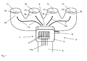
- FIG. 1 schematically shows a first embodiment of the inlet portion 5 of an internal combustion engine in an inclined plan view.
- the internal combustion engine comprises four cylinders 1a, 1b, 1c, 1d arranged in series along the longitudinal axis of the cylinder head.
- the cylinders 1a, 1b, 1c, 1d of the internal combustion engine are supplied with fresh air or combustion air 11a via the total intake line 6.
- a heater 7 for heating the combustion air 11 a is arranged.
- the Bacansaug him 6 goes to form a manifold node 4 in a plurality of intake manifolds 3a, 3b, 3c, 3d, which lead to the inlet openings 2a, 2b, 2c, 2d of the individual cylinders 1a, 1b, 1c, 1d.
- the heating device 7 has a multiplicity of band-shaped heating elements 8, which are oriented substantially vertically to a parallel to the longitudinal axis of the cylinder head, ie extend, and with a first narrow side of its cross section, face the sucked combustion air flow 11a.
- the heating elements 8 are received by a flange 9 and are electrically heated.
- An electrical connection 10 is provided.
- the combustion air 11a sucked in via the entire intake line 6 is heated as it flows through the activated heating device 7.
- the heated combustion air 11b is then, d. H. downstream of the heating device 7, distributed at the distribution node 4 to the individual cylinders 1a, 1b, 1c, 1d.
- FIG. 1 illustrated embodiment of an inlet portion 5 is characterized in that the heating device 7 is disposed adjacent to the distribution node 4, wherein the distance ⁇ between the heater 7 and the distribution node 4 is smaller than the diameter d of a cylinder 1a, 1b, 1c, 1d.
- FIG. 2a schematically shows a first embodiment of the band-shaped heating element 8 in cross section.
- the heating element 8 has a rectangular cross-section 8b in its basic form and faces, with a first narrow side 8a of the cross-section 8b, the intake combustion air flow 11a.
- FIG. 2b schematically shows a second embodiment of the band-shaped heating element 8 in cross section. It should only the differences to the in FIG. 2a Otherwise, reference will be made to FIG. 2a , The same reference numerals have been used for the same components.
- the cross section 8b tapers towards the first narrow side 8a, and thus the band-shaped heating element 8 tapers towards a first narrow end face 8c, which faces the aspirated combustion air flow 11a.
- FIG. 2c schematically shows a third embodiment of the band-shaped heating element 8 in cross section. It should only the differences to the in FIG. 2a Otherwise, reference will be made to FIG. 2a , The same reference numerals have been used for the same components.
- the first narrow side 8a of the cross section 8b tapers, and thus the first narrow end face 8c of the Heating element 8 to the intake combustion air flow 11a, ie against the flow direction.
- FIG. 2d schematically shows a fourth embodiment of the band-shaped heating element 8 in cross section. It should only the differences to the in FIG. 2a Otherwise, reference will be made to FIG. 2a , The same reference numerals have been used for the same components.
- the band-shaped heating element 8 has a blade-like shape with a concave side 8d and a convex side.
Abstract
Description
Die Erfindung betrifft eine Brennkraftmaschine mit mindestens einem Zylinderkopf und mindestens zwei Zylindern, bei der jeder Zylinder mindestens eine Einlaßöffnung zum Zuführen von Verbrennungsluft in den Zylinder aufweist, wobei
- zu jeder Einlaßöffnung eine Ansaugleitung führt,
- die Ansaugleitungen von mindestens zwei Zylindern unter Ausbildung eines Verteilerknotenpunktes zu einer Gesamtansaugleitung zusammenführen, und
- in der Gesamtansaugleitung eine Heizvorrichtung angeordnet ist, die mindestens ein bandförmiges Heizelement aufweist, welches mit einer ersten schmalen Seite des Querschnitts der angesaugten Verbrennungsluftströmung zugewandt ist.
- leads to each inlet opening a suction line,
- merge the suction lines of at least two cylinders to form a manifold node to a Gesamtansaugleitung, and
- in the Gesamtansaugleitung a heating device is arranged, which has at least one band-shaped heating element, which faces with a first narrow side of the cross section of the sucked combustion air flow.
Des Weiteren betrifft die Erfindung ein Verfahren zum Betreiben einer derartigen Brennkraftmaschine.Furthermore, the invention relates to a method for operating such an internal combustion engine.
Im Rahmen der vorliegenden Erfindung umfaßt der Begriff Brennkraftmaschine insbesondere Ottomotoren, aber auch Dieselmotoren und Hybrid-Brennkraftmaschinen.In the context of the present invention, the term internal combustion engine includes in particular gasoline engines, but also diesel engines and hybrid internal combustion engines.
Brennkraftmaschinen verfügen über einen Zylinderblock und mindestens einen Zylinderkopf, die zur Ausbildung der Zylinder miteinander verbunden werden. Um den Ladungswechsel zu steuern, benötigt eine Brennkraftmaschine Steuerorgane - in der Regel in Gestalt von Ventilen - und Betätigungseinrichtungen zur Betätigung dieser Steuerorgane. Der für die Bewegung der Ventile erforderliche Ventilbetätigungsmechanismus einschließlich der Ventile selbst wird als Ventiltrieb bezeichnet. Häufig dient der Zylinderkopf zur Aufnahme des Ventiltriebs.Internal combustion engines have a cylinder block and at least one cylinder head, which are connected together to form the cylinder. In order to control the charge cycle, an internal combustion engine requires controls - usually in the form of valves - and actuators to operate these controls. The required for the movement of the valves valve actuating mechanism including the valves themselves is referred to as a valve train. Often, the cylinder head serves to accommodate the valve train.
Im Rahmen des Ladungswechsels erfolgt das Ausschieben der Verbrennungsgase über die Auslaßöffnungen der Zylinder und das Füllen der Brennräume, d. h. das Ansaugen der Verbrennungsluft über die Einlaßöffnungen. Ist die Brennkraftmaschine mit einer Abgasrückführung ausgestattet, kann die Verbrennungsluft neben der aus der Umgebung angesaugten Frischluft auch Abgas enthalten. Wird der Kraftstoff nicht direkt in die Zylinder eingespritzt, sondern beispielsweise stromaufwärts der Zylinder in den Ansaugtrakt eingebracht, wird nicht nur die Verbrennungsluft, sondern vielmehr auch der Kraftstoff den Zylindern via Einlaßöffnungen zugeführt.As part of the charge exchange, the expulsion of the combustion gases via the outlet openings of the cylinder and the filling of the combustion chambers, ie the suction of the combustion air via the inlet openings takes place. If the internal combustion engine is equipped with exhaust gas recirculation, the combustion air can also contain exhaust gas in addition to the fresh air sucked in from the environment. Does not the fuel directly into the cylinder injected, but introduced, for example, upstream of the cylinder in the intake, not only the combustion air, but also the fuel is supplied to the cylinders via inlet ports.
Es ist die Aufgabe des Ventiltriebes die Einlaß- und Auslaßöffnungen rechtzeitig freizugeben bzw. zu schließen, wobei eine schnelle Freigabe möglichst großer Strömungsquerschnitte angestrebt wird, um die Drosselverluste in den ein- bzw. ausströmenden Gasströmungen gering zu halten und eine möglichst gute Füllung des Brennraumes mit Frischgemisch bzw. ein effektives, d. h. vollständiges Abführen der Abgase zu gewährleisten.It is the task of the valve train to open the intake and exhaust ports in time or close, with a quick release of the largest possible flow cross sections is sought to keep the throttle losses in the incoming and outflowing gas flows low and the best possible filling of the combustion chamber Fresh mixture or an effective, d. H. To ensure complete removal of the exhaust gases.
Die Ansaugleitungen, die zu den Einlaßöffnungen führen, sind nach dem Stand der Technik zumindest teilweise im Zylinderkopf integriert und werden in der Regel unter Ausbildung mindestens eines sogenannten Einlaßkrümmers zusammengeführt; häufig zu einer einzelnen Gesamtansaugleitung.The intake ducts leading to the inlet openings are at least partially integrated in the cylinder head according to the prior art and are usually brought together to form at least one so-called intake manifold; often to a single overall suction line.
An den Einlaßbereich einer Brennkraftmaschine werden unterschiedliche Anforderungen gestellt. So wird unter anderem eine Anordnung und Ausbildung der Ansaugleitungen angestrebt, die zu einem möglichst geringen Druckverlust in der angesaugten Verbrennungsluft führt, um eine gute Füllung der Zylinder mit Frischgemisch zu gewährleisten.At the inlet region of an internal combustion engine, different requirements. Thus, inter alia, an arrangement and design of the suction lines is sought, which leads to the lowest possible pressure loss in the intake combustion air in order to ensure a good filling of the cylinder with fresh mixture.
Die Geometrie einer Ansaugleitung hat zudem Einfluß auf die Ladungsbewegung im Zylinder und damit auf die Gemischbildung, insbesondere bei direkteinspritzenden Brennkraftmaschinen. Häufig werden die Ansaugleitungen daher im Hinblick auf die Erzeugung eines sogenannten Tumbles oder einer Drallströmung ausgebildet, die die Gemischbildung beschleunigen und unterstützen, wobei ein Tumble ein Luftwirbel um eine gedachte Achse ist, die parallel zur Längsachse der Kurbelwelle verläuft, und ein Drall einen Luftwirbel bezeichnet, dessen Achse parallel zur Kolben- bzw. Zylinderlängsachse verläuft.The geometry of an intake line also has an influence on the charge movement in the cylinder and thus on the mixture formation, especially in direct-injection internal combustion engines. Frequently, therefore, the suction lines are formed with a view to generating a so-called tumbles or swirling flow which accelerate and assist mixture formation, a tumble being an air vortex about an imaginary axis parallel to the longitudinal axis of the crankshaft and a swirl designating an air vortex whose axis is parallel to the piston or cylinder longitudinal axis.
Während des Ladungswechsels variiert der Druck entlang des Strömungsweges im Ansaugkanal. Derartige lokale Druckschwankungen breiten sich in gasförmigen Medien als Wellen aus. Um diese dynamischen Wellenvorgänge für die Optimierung des Ladungswechsels nutzbar zu machen, kann beispielsweise der Einlaßbereich in der Art ausgelegt werden, dass gegen Ende des Ansaugtaktes an den Einlaßöffnungen eine Überdruckwelle ankommt, die zu einer Verdichtung und damit zu einem gewissen Nachladeeffekt führt. Zielführend sind dabei in der Länge variable Ansaugleitungen.During the charge cycle, the pressure varies along the flow path in the intake passage. Such local pressure fluctuations propagate in gaseous media as waves. To make these dynamic wave processes usable for the optimization of the charge exchange, for example, the inlet area can be designed in such a way that at the inlet openings towards the end of the intake stroke Overpressure wave arrives, which leads to a compression and thus to a certain reloading effect. Targeting are in length variable suction lines.
In die Ansaugleitung bzw. Gesamtansaugleitung kann eine Vielzahl von zusätzlichen Leitungen einmünden, beispielsweise die Rückführleitung einer Abgasrückführung oder die Bypaßleitung eines Ladeluftkühlers bzw. eines Verdichters.In the intake or Gesamtansaugleitung can open a variety of additional lines, such as the return line of an exhaust gas recirculation or the bypass line of a charge air cooler or a compressor.
Darüber hinaus können Brennkraftmaschinen mit einer Heizvorrichtung ausgestattet werden, die im Einlaßbereich, d. h. Ansaugbereich, angeordnet ist und der Erwärmung der Ansaugluft dient.In addition, internal combustion engines can be equipped with a heating device, which in the inlet area, d. H. Intake, is arranged and the heating of the intake air is used.
Das Erwärmen der Ansaugluft kann unterschiedlichen Zielsetzungen dienen, beispielsweise der Verkürzung der Warmlaufphase nach einem Kaltstart, wie in der
Die deutsche Offenlegungsschrift
Eine für den Einsatz bei Brennkraftmaschinen geeignete Heizvorrichtung wird beispielsweise in der deutschen Offenlegungsschrift
Diese aus dem Stand der Technik bekannten Heizvorrichtungen umfassen bandförmige Heizelemente, die elektrisch beheizbar sind und einen in der Grundform rechteckigen Querschnitt aufweisen. Die bandförmigen Heizelemente werden in der Weise im Einlaßbereich angeordnet, dass ihr rechteckförmiger Querschnitt für die angesaugte Verbrennungsluft einen möglichst kleinen Widerstand darstellt. Mit einer ersten schmalen Seite des Querschnitts sind die bandförmigen Heizelemente der angesaugten Verbrennungsluftströmung zugewandt, wohingegen die langen Seiten des rechteckförmigen Querschnitts sich in Strömungsrichtung erstrecken, so dass die angesaugte Verbrennungsluft tangential über die größeren Längsseiten strömt. Eine derartige Ausrichtung des Querschnitts ist strömungstechnisch günstig, aber auch im Hinblick auf den Wärmeübergang infolge Konvektion vorteilhaft.These known from the prior art heating devices comprise band-shaped heating elements, which are electrically heated and have a rectangular in cross-section in the basic form. The band-shaped heating elements are arranged in the inlet region in such a way that their rectangular cross-section represents the smallest possible resistance to the intake combustion air. With a first narrow side of the cross section, the band-shaped heating elements face the intake combustion air flow, whereas the long sides of the rectangular cross-section extend in the flow direction, so that the intake combustion air flows tangentially over the larger longitudinal sides. Such an orientation of the cross section is favorable in terms of flow, but also advantageous with regard to the heat transfer due to convection.
Eine Brennkraftmaschine, bei der in der Gesamtansaugleitung mindestens eine Heizvorrichtung angeordnet ist, die mindestens ein bandförmiges Heizelement aufweist, welches mit einer ersten schmalen Seite des Querschnitts der angesaugten Verbrennungsluftströmung zugewandt ist, ist auch Gegenstand der vorliegenden Erfindung.An internal combustion engine in which at least one heating device is arranged in the Gesamtansuctionleitung having at least one band-shaped heating element, which faces with a first narrow side of the cross section of the sucked combustion air flow, is also an object of the present invention.
Die Anordnung der Heizvorrichtung im Ansaugbereich einer Brennkraftmaschine wird gemäß der
Vor dem Hintergrund des oben Gesagten ist es eine Aufgabe der vorliegenden Erfindung, eine Brennkraftmaschine gemäß dem Oberbegriff des Anspruchs 1 bereitzustellen, die hinsichtlich der Anordnung der Heizvorrichtung im Ansaugbereich optimiert ist.In light of the above, it is an object of the present invention to provide an internal combustion engine according to the preamble of claim 1, which is optimized with respect to the arrangement of the heater in the intake region.
Eine weitere Teilaufgabe der vorliegenden Erfindung ist es, ein Verfahren zum Betreiben einer derartigen Brennkraftmaschine aufzuzeigen.A further sub-task of the present invention is to show a method for operating such an internal combustion engine.
Gelöst wird die erste Teilaufgabe durch eine Brennkraftmaschine mit mindestens einem Zylinderkopf und mindestens zwei Zylindern, bei der jeder Zylinder mindestens eine Einlaßöffnung zum Zuführen von Verbrennungsluft in den Zylinder aufweist, wobei
- zu jeder Einlaßöffnung eine Ansaugleitung führt,
- die Ansaugleitungen von mindestens zwei Zylindern unter Ausbildung eines Verteilerknotenpunktes zu einer Gesamtansaugleitung zusammenführen, und
- in der Gesamtansaugleitung eine Heizvorrichtung angeordnet ist, die mindestens ein bandförmiges Heizelement aufweist, welches mit einer ersten schmalen Seite des Querschnitts der angesaugten Verbrennungsluftströmung zugewandt ist,
- die Heizvorrichtung benachbart zu dem Verteilerknotenpunkt angeordnet ist, in dem die Ansaugleitungen zu der Gesamtansaugleitung zusammenführen, wobei der Abstand Δ zwischen der Heizvorrichtung und dem Verteilerknotenpunkt kleiner ist als der Durchmesser d eines Zylinders mit Δ < d.
- leads to each inlet opening a suction line,
- merge the suction lines of at least two cylinders to form a manifold node to a Gesamtansaugleitung, and
- in the Gesamtansaugleitung a heating device is arranged, which has at least one band-shaped heating element, which faces with a first narrow side of the cross section of the sucked combustion air flow,
- the heating device is arranged adjacent to the distribution node, in which the suction lines merge to form the total intake line, wherein the distance Δ between the heating device and the distribution node is smaller than the diameter d of a cylinder with Δ < d .
Bei der erfindungsgemäßen Brennkraftmaschine ist die Heizvorrichtung möglichst nahe an den Einlaßöffnungen der Zylinder angeordnet, nämlich benachbart zu dem Verteilerknotenpunkt eines Einlaßkrümmers, an dem die einzelnen Ansaugleitungen zu den mindestens zwei Zylindern abzweigen. Diese Anordnung unterstützt die Heizvorrichtung in ihrer eigentlichen Funktion, nämlich den Zylindern vorerwärmte Verbrennungsluft zur Verfügung zu stellen, d. h. zu zuführen.In the internal combustion engine according to the invention, the heater is arranged as close as possible to the inlet openings of the cylinder, namely adjacent to the distribution node of an intake manifold, at which branch off the individual intake to the at least two cylinders. This arrangement assists the heater in its proper function of providing the cylinders with preheated combustion air, i. H. to feed.
Durch die Anordnung der Heizvorrichtung nahe am Verteilerknotenpunkt wird der Weg der vorerwärmten Verbrennungsluft zu den Zylindern weitestgehend verkürzt. Damit wird der vorerwärmten Verbrennungsluft möglichst wenig Wegstrecke und Zeit zur Abkühlung eingeräumt. Die thermische Trägheit des Teilstücks der Ansaugleitungen zwischen der Einlaßöffnung am Zylinder und der Heizvorrichtung wird minimiert und zwar durch Reduzierung der Masse und der Länge dieses Teilstückes.The arrangement of the heater close to the distribution hub, the way the preheated combustion air to the cylinders is largely shortened. Thus, the preheated combustion air is given as little as possible distance and time for cooling. The thermal inertia of the portion of the suction lines between the inlet port on the cylinder and the heater is minimized by reducing the mass and the length of this section.
Diese Maßnahme stellt sicher, dass die Verbrennungsluft bei Eintritt in die Zylinder eine möglichst hohe Temperatur aufweist, wodurch sich insbesondere die Warmlaufphase nach einem Kaltstart der Brennkraftmaschine deutlich verkürzt. Vorteile bietet dies insbesondere hinsichtlich der Schadstoffemissionen.This measure ensures that the combustion air when entering the cylinder has the highest possible temperature, which in particular significantly reduces the warm-up phase after a cold start of the internal combustion engine. This offers advantages in particular with regard to pollutant emissions.
Zu berücksichtigen ist in diesem Zusammenhang, dass eine zügige Aufheizung der Brennkraftmaschine mittels vorerwärmter Ansaugluft auch zu einer schnelleren, vorliegend indirekten Erwärmung des Motoröls führt. Die damit einhergehende Abnahme der Viskosität bedingt eine Verringerung der Reibung bzw. Reibleistung, insbesondere in den mit Öl versorgten Lagern. Ein Effekt der sich vorteilhaft auf den Kraftstoffverbrauch auswirkt.It should be noted in this context that a rapid heating of the internal combustion engine by means of preheated intake air also leads to a faster, in this case indirect heating of the engine oil. The concomitant decrease in viscosity causes a reduction in friction or friction, especially in the oil-supplied bearings. An effect that has an advantageous effect on fuel consumption.
Vorteilhaft sind Ausführungsformen der Brennkraftmaschine, bei denen die Ansaugleitungen von mindestens zwei Zylindern unter Ausbildung eines Einlaßkrümmers innerhalb des mindestens einen Zylinderkopfes zu einer Gesamtansaugleitung zusammenführen. Die Integration des Einlaßkrümmers in den Zylinderkopf verkürzt die vorliegend relevante Wegstrecke der Ansaugleitungen weiter und damit die thermische Trägheit des Teilstücks der Ansaugleitungen zwischen dem Zylindereinlaß und der Heizvorrichtung. Diese Maßnahme gestattet darüber hinaus ein dichtes Packaging der Antriebseinheit und verringert die Anzahl an Bauteilen und damit die Montage- und Bereitstellungskosten.Embodiments of the internal combustion engine are advantageous in which the intake lines of at least two cylinders, forming an intake manifold within the bring together at least one cylinder head to a Gesamtansaugleitung. The integration of the intake manifold into the cylinder head further shortens the presently relevant travel distance of the intake manifolds and hence the thermal inertia of the portion of the intake manifolds between the cylinder intake and the heater. This measure also allows tight packaging of the drive unit and reduces the number of components and thus the installation and deployment costs.
Nichtsdestotrotz können Ausführungsformen der Brennkraftmaschine vorteilhaft sein, bei denen die Ansaugleitungen von mindestens zwei Zylindern außerhalb des mindestens einen Zylinderkopfes zu einer Gesamtansaugleitung zusammenführen und einen externen Einlaßkrümmer ausbilden.Nonetheless, embodiments of the internal combustion engine may be advantageous in which the intake lines of at least two cylinders outside the at least one cylinder head merge to form an overall intake manifold and form an external intake manifold.
Die erfindungsgemäße Anordnung der Heizvorrichtung nahe des Verteilerknotenpunktes löst die erste der Erfindung zugrunde liegende Aufgabe, nämlich eine Brennkraftmaschine bereitzustellen, die hinsichtlich der Anordnung der Heizvorrichtung im Ansaugbereich optimiert ist.The inventive arrangement of the heating device near the distribution hub solves the first object underlying the invention, namely to provide an internal combustion engine, which is optimized in terms of the arrangement of the heater in the intake.
Im Gegensatz zu den aus dem Stand der Technik bekannten Konzepten ermöglicht die erfindungsgemäße nahe Anordnung der Heizvorrichtung an den Zylindern, die bandförmigen Heizelemente derart auszurichten bzw. auszubilden, dass diese eine gleichmäßige Verteilung der angesaugten Verbrennungsluft auf die einzelnen Zylinder unterstützen. Die Heizvorrichtung dient dabei auch als Leitvorrichtung für die Verbrennungsluft.In contrast to the concepts known from the prior art, the close arrangement of the heating device according to the invention on the cylinders makes it possible to align or form the band-shaped heating elements in such a way that they promote a uniform distribution of the intake combustion air to the individual cylinders. The heater also serves as a guide for the combustion air.
Vorteilhaft sind Ausführungsformen der Brennkraftmaschine, bei denen die erste schmale Seite des Querschnitts des mindestens einen bandförmigen Heizelementes im Wesentlichen senkrecht zu der angesaugten Verbrennungsluftströmung steht.Embodiments of the internal combustion engine in which the first narrow side of the cross section of the at least one band-shaped heating element is substantially perpendicular to the intake combustion air flow are advantageous.
Eine erfindungsgemäße Brennkraftmaschine kann auch zwei Zylinderköpfe aufweisen, beispielsweise, wenn mehrere Zylinder auf zwei Zylinderbänke verteilt angeordnet sind.An internal combustion engine according to the invention may also have two cylinder heads, for example, when a plurality of cylinders are arranged distributed on two cylinder banks.
Erfindungsgemäß müssen nicht die Ansaugleitungen sämtlicher Zylinder eines Zylinderkopfes zu einer Gesamtansaugleitung zusammenführen, sondern nur die Ansaugleitungen von mindestens zwei Zylindern.According to the invention, the suction lines of all the cylinders of a cylinder head need not merge to form a total intake line, but only the intake lines of at least two cylinders.
Vorteilhaft sind aber auch Ausführungsformen, bei denen die Ansaugleitungen sämtlicher Zylinder des mindestens einen Zylinderkopfes zu einer Gesamtansaugleitung zusammenführen.However, embodiments in which the intake lines of all the cylinders of the at least one cylinder head merge to form a total intake line are also advantageous.
Die Ansaugleitungen können auch unter Ausbildung von zwei Verteilerknotenpunkten zu zwei Gesamtansaugleitungen zusammenführen, wenn mehr als zwei Zylinder und/oder mehr als eine Einlaßöffnung je Zylinder vorgesehen sind. Gegebenenfalls sind dann zwei Heizvorrichtungen vorzusehen.The intake ducts may also merge to form two total intake ducts, forming two distributor junctions, if more than two cylinders and / or more than one intake port per cylinder are provided. If necessary, then two heaters are provided.
Weitere vorteilhafte Ausführungsformen der Brennkraftmaschine werden im Zusammenhang mit den Unteransprüchen erörtert.Further advantageous embodiments of the internal combustion engine are discussed in connection with the subclaims.
Vorteilhaft sind Ausführungsformen der Brennkraftmaschine, bei denen der Abstand Δ zwischen der Heizvorrichtung und dem Verteilerknotenpunkt kleiner ist als der halbe Durchmesser d eines Zylinders mit Δ < 0.5d.Advantageous embodiments of the internal combustion engine, in which the distance Δ between the heater and the distribution node is less than half the diameter d of a cylinder with Δ <0.5d.
Vorteilhaft sind insbesondere Ausführungsformen der Brennkraftmaschine, bei denen der Abstand Δ zwischen der Heizvorrichtung und dem Verteilerknotenpunkt kleiner ist als ein Viertel des Durchmesser d eines Zylinders mit Δ < 0.25d.Particularly advantageous embodiments of the internal combustion engine, in which the distance Δ between the heater and the distribution node is less than a quarter of the diameter d of a cylinder with Δ <0.25 d .
Die zusätzliche Verkürzung des Abstandes Δ zwischen der Heizvorrichtung und dem Verteilerknotenpunkt gemäß den beiden vorstehend genannten Ausführungsformen trägt dazu bei, die Wegstrecke zu den Zylindern für die vorerwärmte Verbrennungsluft weiter zu verkürzen, d. h. die thermische Trägheit des Teilstücks der Ansaugleitungen zwischen dem Zylindereinlaß und der Heizvorrichtung zu vermindern.The additional shortening of the distance Δ between the heating device and the distribution node according to the two aforementioned embodiments helps to further shorten the distance to the cylinders for the preheated combustion air, i. H. reduce the thermal inertia of the portion of the suction lines between the cylinder inlet and the heater.
Als Abstand Δ zwischen der Heizvorrichtung und dem Verteilerknotenpunkt wird im Rahmen der vorliegenden Erfindung die Wegstrecke zwischen dem Austritt aus der Heizvorrichtung und der Mitte des Verteilerknotenpunktes, in dem sich die mittleren Stromfäden der Ansaugleitungen treffen, bezeichnet.In the context of the present invention, the distance Δ between the heater and the distribution node is the distance between the exit from the heating device and the center of the distribution node in which the middle flow threads of the suction lines meet.
Bei Brennkraftmaschinen, bei denen die mindestens zwei Zylinder entlang der Längsachse des mindestens einen Zylinderkopfes in Reihe angeordnet sind, sind Ausführungsformen vorteilhaft, die dadurch gekennzeichnet sind, dass das mindestens eine bandförmige Heizelement im Wesentlichen horizontal entlang einer Parallelen zur Längsachse, vorzugsweise parallel zur Längsachse, des mindestens einen Zylinderkopfes ausgerichtet ist.In internal combustion engines, in which the at least two cylinders are arranged along the longitudinal axis of the at least one cylinder head in series, embodiments are advantageous, which are characterized in that the at least one band-shaped Heating element is aligned substantially horizontally along a parallel to the longitudinal axis, preferably parallel to the longitudinal axis of the at least one cylinder head.
Untersuchungen haben gezeigt, dass eine horizontale Ausrichtung der Heizelemente hinsichtlich der Verteilung der angesaugten Verbrennungsluft auf die einzelnen Zylinder vorteilhaft ist und auch Vorteile hinsichtlich des Füllungsgrades bietet.Investigations have shown that a horizontal orientation of the heating elements with regard to the distribution of the intake combustion air to the individual cylinders is advantageous and also offers advantages in terms of degree of filling.
Bei Brennkraftmaschinen der in Rede stehenden Art, bei der die mindestens zwei Zylinder entlang der Längsachse des mindestens einen Zylinderkopfes in Reihe angeordnet sind, sind insbesondere Ausführungsformen vorteilhaft, die dadurch gekennzeichnet sind, dass das mindestens eine bandförmige Heizelement im Wesentlichen vertikal quer, vorzugsweise senkrecht, zu einer Parallelen der Längsachse des mindestens einen Zylinderkopfes ausgerichtet ist.In internal combustion engines of the type in question, in which the at least two cylinders are arranged along the longitudinal axis of the at least one cylinder head in series, particular embodiments are advantageous, which are characterized in that the at least one band-shaped heating element substantially vertically transversely, preferably vertically, is aligned with a parallel of the longitudinal axis of the at least one cylinder head.
Eine derartige Ausrichtung der bandförmigen Heizelemente ist besonders geeignet, um die Heizelemente als Leiteinrichtung für die erwärmte Luftströmung auszubilden bzw. zu nutzen. Mit einer solchen Leiteinrichtung kann die angesaugte Verbrennungsluft in vorteilhafter Weise geführt und gelenkt werden, in der Art, dass eine gleichmäßige Verteilung der Luft auf die einzelnen Zylinder erfolgt. Eine gleichmäßige Füllung der Zylinder mit Frischgemisch wird angestrebt. Dadurch verbessert sich das Betriebsverhalten der Brennkraftmaschine, insbesondere im Hinblick auf die Schadstoffemissionen, den Kraftstoffverbrauch und die verfügbare Leistung.Such an orientation of the band-shaped heating elements is particularly suitable to form or use the heating elements as a guide for the heated air flow. With such a guide, the intake combustion air can be guided and directed in an advantageous manner, in such a way that a uniform distribution of air is carried out on the individual cylinders. A uniform filling of the cylinder with fresh mixture is sought. This improves the operating behavior of the internal combustion engine, in particular with regard to the pollutant emissions, the fuel consumption and the available power.
Vorteilhaft sind Ausführungsformen der Brennkraftmaschine, bei denen sich das mindestens eine bandförmige Heizelement zu einer ersten schmalen Stirnseite hin, die der angesaugten Verbrennungsluftströmung zugewandt ist, verjüngt.Embodiments of the internal combustion engine in which the at least one band-shaped heating element tapers toward a first narrow end side facing the intake combustion air flow are advantageous.
Es ergeben sich strömungstechnische Vorteile. Dadurch, dass sich die Heizelemente entgegengesetzt zur Strömungsrichtung verjüngen, werden beim Auftreffen der Luftströmung auf die Heizvorrichtung weniger Turbulenzen erzeugt. Zudem verengt sich der Strömungsquerschnitt der Gesamtansaugleitung nicht sprunghaft, sondern kontinuierlich, wodurch die Einschnürung der Luftteilströmungen nicht schlagartig erfolgt. Dabei schneiden die Heizelemente messerartig in die sie anströmende Luft ein. Der Widerstand, den die Heizvorrichtung der Luftströmung entgegensetzt, wird durch die beschriebene Ausbildung des mindestens einen bandförmigen Heizelementes verkleinert, wodurch auch der sich über die Heizvorrichtung einstellende Druckverlust verringert wird. Mit der in Rede stehenden Ausführungsform wird einer Verschlechterung des Füllungsgrades infolge der Heizvorrichtung entgegen gewirkt.This results in fluidic advantages. Due to the fact that the heating elements taper opposite to the direction of flow, less turbulence is generated when the air flow hits the heating device. In addition, the flow cross-section of the total intake line does not narrow abruptly, but continuously, whereby the constriction of the partial air flows is not abrupt. The heating elements cut like a knife into the incoming air. The resistance that the heater opposes to the air flow is determined by the described embodiment the at least one band-shaped heating element is reduced, whereby the adjusting itself via the heater pressure loss is reduced. With the embodiment in question, a deterioration of the degree of filling due to the heater is counteracted.
Vorteilhaft sind auch aus den vorstehend genannten Gründen Ausführungsformen der Brennkraftmaschine, bei denen sich eine erste schmale Stirnseite des mindestens einen bandförmigen Heizelementes, die der angesaugten Verbrennungsluftströmung zugewandt ist, verjüngt.Also advantageous for the above-mentioned reasons embodiments of the internal combustion engine, in which a first narrow end face of the at least one band-shaped heating element, which faces the sucked combustion air flow, tapers.
In diesem Zusammenhang muß zudem berücksichtigt werden, dass moderne Brennkraftmaschinen zunehmend mit einer Abgasrückführung ausgestattet werden, mit der Abgas in den Ansaugbereich zurückgeführt wird. Häufig wird das rückzuführende Abgas gekühlt, bevor es in den Ansaugbereich eingeleitet wird. Dies kann im Hinblick auf die Heizvorrichtung problematisch sein, wenn das Abgas stromaufwärts der Heizvorrichtung in den Ansaugbereich eingeleitet wird.In this context, it must also be considered that modern internal combustion engines are increasingly being equipped with exhaust gas recirculation, with which exhaust gas is returned to the intake. Often the recirculated exhaust gas is cooled before it is introduced into the intake. This may be problematic with respect to the heater when the exhaust gas is introduced into the intake area upstream of the heater.
Unter Umständen wird dem Abgasmassenstrom bei der Kühlung so viel Wärme entzogen, dass einzelne Abgasbestandteile aus dem heißen Abgas auskondensieren und sich in der Heizvorrichtung ablagern. Die auskondensierten Abgasbestandteile können eine klebrige, mit zunehmender Betriebsdauer anwachsende Schicht auf der Oberfläche der Heizelemente aufbauen, an der schließlich auch die festen Bestandteile des Abgasmassenstromes bei Berührung hängen bleiben, insbesondere im Abgas befindliche Rußpartikel. Die Ablagerungen führen zu einem verengten Strömungsquerschnitt, gegebenenfalls zu einem vollständigen Verschluß der Gesamtansaugleitung und verschlechtern den Wärmeübergang vom Heizelement auf die angesaugte Luft. Eine Verengung des Strömungsquerschnittes des Ansaugkanals wäre zudem mit einem Druckverlust in der Ansaugströmung und einer Verschlechterung des Füllungsgrades verbunden.Under certain circumstances, so much heat is removed from the exhaust gas mass flow during cooling that individual exhaust gas components condense out of the hot exhaust gas and deposit in the heating device. The condensed exhaust gas constituents can build up a sticky, with increasing operating time layer on the surface of the heating elements, at the end, even the solid components of the exhaust gas mass flow get caught in contact, especially in the exhaust gas located soot particles. The deposits lead to a narrowed flow cross-section, possibly to a complete closure of the Gesamtansaugleitung and worsen the heat transfer from the heating element to the intake air. A narrowing of the flow cross-section of the intake duct would also be associated with a pressure drop in the intake flow and a deterioration of the degree of filling.
Eine sich verjüngende erste schmale Stirnseite des mindestens einen bandförmigen Heizelementes wirkt derartigen Ablagerungen entgegen. Querschnittsverengungen infolge von Ablagerungen oder gar Kanalblockaden, hervorgerufen durch auskondensierte Abgasbestandteile, sind nicht zu befürchten bzw. wird entgegen gewirkt.A tapering first narrow end face of the at least one band-shaped heating element counteracts such deposits. Cross-sectional constrictions as a result of deposits or even channel blockades, caused by condensed exhaust gas constituents, are not to be feared or counteracted.
Vorteilhaft sind Ausführungsformen der Brennkraftmaschine, bei denen der Querschnitt des mindestens einen bandförmigen Heizelementes bogenförmig ausgebildet ist, so dass das mindestens eine bandförmige Heizelement eine schaufelförmige Gestalt aufweist.Embodiments of the internal combustion engine in which the cross section of the at least one band-shaped heating element is arcuate are advantageous, so that the at least one band-shaped heating element has a blade-shaped form.
Eine bogenförmige Ausbildung des bandförmigen Heizelementes ist vorteilhaft hinsichtlich einer Verwendung der Heizvorrichtung als Leiteinrichtung. Zu berücksichtigen ist dabei, dass der Verteilerknotenpunkt in Bezug auf die mindestens zwei Zylinder in der Regel mittig angeordnet ist, die räumliche Ausdehnung des Knotenpunktes begrenzt ist und die vorerwärmte Luft daher auf dem Weg zu den Zylindern nahezu bei jeder Ausführungsform der Brennkraftmaschine mehr oder weniger stark umzulenken ist.An arcuate design of the band-shaped heating element is advantageous in terms of use of the heater as a guide. It should be noted that the distribution node is usually centered with respect to the at least two cylinders, the spatial extent of the node is limited and the preheated air therefore more or less strongly on the way to the cylinders almost every embodiment of the internal combustion engine is to divert.
Die schaufelförmige Gestalt des mindestens einen bandförmigen Heizelementes gestattet eine verlustfreie bzw. druckverlustarme Umlenkung der angesaugten Verbrennungsluft und eine gleichmäßige Verteilung der Luft auf die einzelnen Zylinder.The blade-like shape of the at least one band-shaped heating element allows a lossless or low-pressure loss deflection of the intake combustion air and a uniform distribution of air to the individual cylinders.
Vorteilhaft sind Ausführungsformen der Brennkraftmaschine, bei denen die Heizvorrichtung mindestens zwei bandförmige Heizelemente aufweist. Mit der Anzahl der Heizelemente nimmt auch die wärmeübertragende Fläche zu und damit die Wärmemenge, die auf die angesaugte Verbrennungsluft übertragbar ist. Der Anzahl an Heizelementen kommt hinsichtlich des Wärmeübergangs eine nicht zu vernachlässigende Bedeutung zu, da die Strömungsgeschwindigkeiten in der Gesamtansaugleitung hoch sind und die Temperatur der Heizelemente und damit die Temperaturdifferenz zwischen den Heizelementen und der Luft nicht beliebig erhöht werden kann, um den Wärmeübergang zu steigern.Embodiments of the internal combustion engine in which the heating device has at least two band-shaped heating elements are advantageous. With the number of heating elements and the heat transfer area increases and thus the amount of heat that is transferable to the intake combustion air. The number of heating elements is important in terms of heat transfer to importance, since the flow rates in the Gesamtansaugleitung are high and the temperature of the heating elements and thus the temperature difference between the heating elements and the air can not be increased arbitrarily to increase the heat transfer.
Die Ausbildung der Heizvorrichtung als Leiteinrichtung wird ebenfalls erleichtert, wenn mehrere Heizelemente vorgesehen werden und zur Beeinflussung der Strömung verwendet werden können.The design of the heater as a guide is also facilitated if several heating elements are provided and can be used to influence the flow.
Vorteilhaft sind dabei Ausführungsformen der Brennkraftmaschine, bei denen die mindestens zwei bandförmigen Heizelemente beabstandet zueinander angeordnet sind. Erst auf diese Weise lassen sich die Vorteile, die mehrere Heizelemente bieten, nutzen.Embodiments of the internal combustion engine in which the at least two band-shaped heating elements are arranged at a distance from one another are advantageous. Only in this way, the benefits that provide several heating elements, can be used.
Bei Brennkraftmaschinen mit mindestens zwei bandförmigen Heizelementen, die im Wesentlichen vertikal quer zu einer Parallelen der Längsachse des mindestens einen Zylinderkopfes ausgerichtet sind, haben sich Ausführungsformen als vorteilhaft erwiesen, die dadurch gekennzeichnet sind, dass mindestens zwei bandförmige Heizelemente in einem spitzen Winkel zueinander angestellt sind. Eine derartige Anordnung der Heizelemente fächert den vorerwärmten Luftstrom auf, wodurch dieser auf die Zylinder verteilt wird.In internal combustion engines having at least two band-shaped heating elements, which are substantially vertically transverse to a parallel of the longitudinal axis of the at least one Aligned cylinder head, embodiments have proven to be advantageous, which are characterized in that at least two band-shaped heating elements are employed at an acute angle to each other. Such an arrangement of the heating elements fanned the preheated air flow, whereby this is distributed to the cylinders.
Bei der vorstehend genannten Art von Brennkraftmaschine, bei der die mindestens zwei bandförmigen Heizelemente im Wesentlichen vertikal ausgerichtet sind, sind des Weiteren Ausführungsformen vorteilhaft, bei denen mindestens zwei bandförmige Heizelemente eine schaufelförmige Gestalt aufweisen, wobei die konkave Seite nach außen gewandt ist.In the above-mentioned type of internal combustion engine in which the at least two band-shaped heating elements are aligned substantially vertically, further embodiments are advantageous in which at least two band-shaped heating elements have a blade-like shape, wherein the concave side facing outward.
Nach außen gewandt bedeutet in diesem Zusammenhang, dass die konkave, d. h. die nach innen gewölbte Seite der Wandung der Gesamtansaugleitung bzw. dem die Heizelemente aufnehmenden Flansch der Heizvorrichtung zugewandt und vom mittleren Stromfaden der Verbrennungsluftströmung abgewandt ist. Dabei öffnen sich die mindestens zwei Heizelemente vorzugsweise trichterähnlich.Turning outward in this context means that the concave, d. H. the inwardly curved side of the wall of the Gesamtansaugleitung or the heating elements receiving the flange facing the heater and facing away from the central stream of thread of the combustion air flow. In this case, the at least two heating elements preferably open like a funnel.
Vorteilhaft sind Ausführungsformen der Brennkraftmaschine, bei denen das mindestens eine Heizelement von einem Flansch aufgenommen wird. Diese Ausführungsform gestattet es, die Heizvorrichtung als vormontierte Baugruppe bereitzustellen und Heizvorrichtungen gleicher Bauart in unterschiedlichen Brennkraftmaschinen einzusetzen. Dies erhöht die Stückzahl und senkt damit die Stückkosten. Zudem wird der Austausch einer defekten Heizvorrichtung erleichtert.Embodiments of the internal combustion engine in which the at least one heating element is received by a flange are advantageous. This embodiment makes it possible to provide the heater as a preassembled module and to use heaters of the same type in different internal combustion engines. This increases the number of units and thus reduces the unit costs. In addition, the replacement of a defective heater is facilitated.
Vorteilhaft sind aber auch Ausführungsformen der Brennkraftmaschine, bei denen die Gesamtansaugleitung das mindestens eine Heizelement aufnimmt, d. h. den Flansch als Aufnahme ersetzt.But are also advantageous embodiments of the internal combustion engine, in which the Gesamtansaugleitung receives the at least one heating element, d. H. replaced the flange as a receptacle.
Vorteilhaft sind Ausführungsformen der Brennkraftmaschine, bei denen ein Ladeluftkühler vorgesehen ist, der mit einer Bypaßleitung ausgestattet ist, die stromaufwärts der Heizvorrichtung in die Gesamtansaugleitung mündet.Advantageous embodiments of the internal combustion engine, in which a charge air cooler is provided, which is equipped with a bypass line, which opens upstream of the heater in the Gesamtansaugleitung.
Der Ladeluftkühler senkt die Lufttemperatur und steigert damit die Dichte der Luft, wodurch auch der Kühler zu einer besseren Füllung der Zylinder mit Luft, d. h. zu einer größeren Luftmasse beiträgt. Die Ausstattung des Ladeluftkühlers mit einer Bypaßleitung zwecks Umgehung des Kühlers erweist sich insbesondere nach einem Kaltstart der Brennkraftmaschine bzw. während der Warmlaufphase als vorteilhaft. Eine Kühlung der angesaugten Luft in diesen Betriebszuständen würde dem Erwärmen in der Heizvorrichtung entgegen stehen, d. h. zuwiderlaufen.The intercooler lowers the air temperature and thus increases the density of the air, whereby the cooler also contributes to a better filling of the cylinder with air, ie to a larger air mass. The equipment of the intercooler with a bypass line in order Bypassing of the radiator proves to be particularly advantageous after a cold start of the internal combustion engine or during the warm-up phase. Cooling of the intake air in these operating states would be contrary to the heating in the heater, ie run counter.
Vorteilhaft sind Ausführungsformen der Brennkraftmaschine, bei denen eine externe Abgasrückführung vorgesehen ist, die mit einer Rückführleitung ausgestattet ist, die stromaufwärts der Heizvorrichtung in die Gesamtansaugleitung mündet.Advantageous embodiments of the internal combustion engine, in which an external exhaust gas recirculation is provided, which is equipped with a return line, which opens upstream of the heater in the Gesamtansaugleitung.
Die Rückführung von Verbrennungsgasen von der Abgasseite in den Ansaugbereich wird als zielführend angesehen, um zukünftige Grenzwerte für Stickoxidemissionen einzuhalten, wobei hohe Abgasrückführraten, die in der Größenordnung von xAGR ≈ 60% bis 70% liegen können, erforderlich sind, um eine deutliche Senkung der Stickoxidemissionen zu erreichen.The recirculation of combustion gases from the exhaust side to the intake region is considered to be effective in meeting future nitrogen oxide emission limits, with high exhaust gas recirculation rates, which may be on the order of x AGR ≈ 60% to 70%, to significantly reduce the emissions To achieve nitrogen oxide emissions.
Die Rückführrate xAGR bestimmt sich dabei zu xAGR = mAGR / (mAGR + mFrischluft), wobei mAGR die Masse an zurückgeführtem Abgas und mFrischluft die zugeführte Frischluft bezeichnet.The recirculation rate x AGR is determined to be x AGR = m AGR / (m AGR + m fresh air ), where m AGR designates the mass of recirculated exhaust gas and m fresh air the fresh air supplied.
In der Abgasrückführleitung ist häufig eine Kühlvorrichtung vorgesehen, mit der die Temperatur im heißen Abgasstrom gesenkt wird, wodurch die Dichte der Abgase erhöht wird. Die Temperatur der Verbrennungsluft, die sich bei der Mischung der Frischluft mit den rückgeführten Abgasen einstellt, wird hierdurch ebenfalls gesenkt, weshalb auch die Kühlvorrichtung der Abgasrückführung zu einer besseren Füllung der Zylinder beiträgt. In der Regel wird eine Flüssigkeitskühlung verwendet. Gegebenenfalls ist es vorteilhaft, diese Kühlvorrichtung - wie den Ladeluftkühler - mit einer Bypaßleitung auszustatten.In the exhaust gas recirculation line, a cooling device is often provided, with which the temperature is lowered in the hot exhaust gas flow, whereby the density of the exhaust gases is increased. The temperature of the combustion air, which is established in the mixture of fresh air with the recirculated exhaust gases, is thereby also lowered, which is why the cooling device of the exhaust gas recirculation contributes to a better filling of the cylinder. As a rule, liquid cooling is used. Optionally, it is advantageous to equip this cooling device - such as the intercooler - with a bypass line.
In die Gesamtansaugleitung eingeleitete Gasströme erzeugen Turbulenzen. Mündet die Bypaßleitung eines Ladeluftkühlers und/oder die Rückführleitung einer Abgasrückführung stromaufwärts der Heizvorrichtung in die Gesamtansaugleitung, sorgt die stromabwärts angeordnete Heizvorrichtung auch für eine Beruhigung der Verbrennungsluftströmung.Gas streams introduced into the total intake line generate turbulence. If the bypass line of an intercooler and / or the return line of an exhaust gas recirculation feeds upstream of the heating device into the total intake line, the downstream heating device also ensures a calming of the combustion air flow.
Vorteilhaft sind Ausführungsformen der Brennkraftmaschine, bei denen eine Aufladung vorgesehen ist.Advantageous embodiments of the internal combustion engine, in which a charge is provided.
Die Aufladung dient in erster Linie der Leistungssteigerung der Brennkraftmaschine. Die Aufladung ist aber auch ein geeignetes Mittel, bei gleicher Leistung den Hubraum zu reduzieren, wodurch sich - bei gleichen Fahrzeugrandbedingungen - das Lastkollektiv zu höheren Lasten hin verschieben läßt, wo der spezifische Kraftstoffverbrauch niedriger ist.The charge is used primarily to increase the performance of the internal combustion engine. Charging is also a suitable means to reduce the displacement at the same power, which can - with the same vehicle boundary conditions - the load collective shift to higher loads where the specific fuel consumption is lower.
Die zweite der Erfindung zugrunde liegende Teilaufgabe, nämlich ein Verfahren zum Betreiben einer Brennkraftmaschine einer zuvor beschriebenen Art aufzuzeigen, wird gelöst durch ein Verfahren, das dadurch gekennzeichnet ist, dass
- die Heizvorrichtung zur Erwärmung der Verbrennungsluft aktiviert wird, wenn die Kraftstoffzufuhr der Brennkraftmaschine deaktiviert ist.
- the heating device is activated to heat the combustion air when the fuel supply of the internal combustion engine is deactivated.
Das bereits für die erfindungsgemäße Brennkraftmaschine Gesagte gilt auch für das erfindungsgemäße Verfahren, weshalb auf die entsprechenden Ausführungen Bezug genommen wird.What has already been said for the internal combustion engine according to the invention also applies to the method according to the invention, for which reason reference is made to the corresponding explanations.
Wird die Kraftstoffzufuhr deaktiviert, fehlt die bei der Verbrennung durch die exotherme, chemische Umwandlung des Kraftstoffes freigesetzte Wärme, um die Brennkraftmaschine auf Betriebstemperatur zu halten.When the fuel supply is deactivated, the heat released during combustion by the exothermic chemical conversion of the fuel is lacking to keep the engine at operating temperature.
Daher ist es vorteilhaft, die Heizvorrichtung zur Erwärmung der Verbrennungsluft zu aktivieren, wenn die Kraftstoffzufuhr der Brennkraftmaschine deaktiviert wird.Therefore, it is advantageous to activate the heating device for heating the combustion air when the fuel supply of the internal combustion engine is deactivated.
Vorteilhaft sind dabei Ausführungsformen des Verfahrens, bei denen die Heizvorrichtung zur Erwärmung der Verbrennungsluft aktiviert wird, wenn die Kraftstoffzufuhr der Brennkraftmaschine für eine vorgebbare Zeitspanne Δt1 deaktiviert ist.Embodiments of the method in which the heating device is activated to heat the combustion air are advantageous if the fuel supply of the internal combustion engine is deactivated for a predefinable time interval Δt 1 .
Die Einführung einer zusätzlichen Bedingung für das Aktivieren der Heizvorrichtung soll ein zu häufiges An- und Abschalten der Heizvorrichtung verhindern, insbesondere ein Aktivieren der Heizvorrichtung, wenn die Kraftstoffzufuhr nur kurzzeitig deaktiviert wird, ohne dass ein Erwärmen der Ansaugluft mittels Heizvorrichtung erforderlich wäre.The introduction of an additional condition for activating the heater is to prevent too frequent switching on and off of the heater, in particular activation of the heater when the fuel supply is only briefly deactivated, without heating the intake air would be required by means of heating.
Im Folgenden wird die Erfindung anhand eines Ausführungsbeispiels gemäß den
- Fig. 1
- schematisch eine erste Ausführungsform des Einlaßbereiches einer Brennkraftmaschine in einer schräg angestellten Draufsicht, und
- Fig.2a
- schematisch eine erste Ausführungsform eines bandförmigen Heizelementes im Querschnitt, und
- Fig.2b
- schematisch eine zweite Ausführungsform eines bandförmigen Heizelementes im Querschnitt, und
- Fig.2c
- schematisch eine dritte Ausführungsform eines bandförmigen Heizelementes im Querschnitt, und
- Fig.2d
- schematisch eine vierte Ausführungsform eines bandförmigen Heizelementes im Querschnitt.
- Fig. 1
- schematically a first embodiment of the inlet region of an internal combustion engine in an inclined plane view, and
- 2a
- schematically a first embodiment of a band-shaped heating element in cross section, and
- 2b
- schematically a second embodiment of a band-shaped heating element in cross section, and
- Figure 2c
- schematically a third embodiment of a band-shaped heating element in cross section, and
- Figure 2d
- schematically a fourth embodiment of a band-shaped heating element in cross section.
Die Zylinder 1a, 1b, 1c, 1d der Brennkraftmaschine werden via Gesamtansaugleitung 6 mit Frischluft bzw. Verbrennungsluft 11a versorgt. In der Gesamtansaugleitung 6 ist eine Heizvorrichtung 7 zur Erwärmung der Verbrennungsluft 11a angeordnet.The
Stromabwärts der Heizvorrichtung 7 geht die Gesamtansaugleitung 6 unter Ausbildung eines Verteilerknotenpunktes 4 in mehrere Ansaugleitungen 3a, 3b, 3c, 3d über, die zu den Einlaßöffnungen 2a, 2b, 2c, 2d der einzelnen Zylinder 1a, 1b, 1c, 1d führen.Downstream of the
Die Heizvorrichtung 7 weist eine Vielzahl von bandförmigen Heizelementen 8 auf, die im Wesentlichen vertikal zu einer Parallelen der Längsachse des Zylinderkopfes ausgerichtet sind, d. h. verlaufen, und mit einer ersten schmalen Seite ihres Querschnitts der angesaugten Verbrennungsluftströmung 11a zugewandt sind. Die Heizelemente 8 werden von einem Flansch 9 aufgenommen und sind elektrisch beheizbar. Ein elektrischer Anschluß 10 ist vorgesehen.The
Die via Gesamtansaugleitung 6 angesaugte Verbrennungsluft 11a wird beim Durchströmen der aktivierten Heizvorrichtung 7 erwärmt. Die erwärmte Verbrennungsluft 11b wird anschließend, d. h. stromabwärts der Heizvorrichtung 7, am Verteilerknotenpunkt 4 auf die einzelnen Zylinder 1a, 1b, 1c, 1d verteilt.The
Die in
Im Unterschied zu der in
Im Unterschied zu der in
Im Unterschied zu der in
- 1a1a
- Zylindercylinder
- 1b1b
- Zylindercylinder
- 1c1c
- Zylindercylinder
- 1d1d
- Zylindercylinder
- 2a2a
- Einlaßöffnunginlet port
- 2b2 B
- Einlaßöffnunginlet port
- 2c2c
- Einlaßöffnunginlet port
- 2d2d
- Einlaßöffnunginlet port
- 3a3a
- Ansaugleitungsuction
- 3b3b
- Ansaugleitungsuction
- 3c3c
- Ansaugleitungsuction
- 3d3d
- Ansaugleitungsuction
- 44
- VerteilerknotenpunktDistribution hub
- 55
- Einlaßbereich, AnsaugbereichInlet area, intake area
- 66
- GesamtansaugleitungGesamtansaugleitung
- 77
- Heizvorrichtungheater
- 88th
- Heizelementeheating elements
- 8a8a
- erste schmale Seite des Querschnittsfirst narrow side of the cross section
- 8b8b
- Querschnitt eines HeizelementesCross section of a heating element
- 8c8c
- erste schmale Stirnseite eines Heizelementesfirst narrow end face of a heating element
- 8d8d
- konkave Seite eines schaufelförmigen Heizelementesconcave side of a paddle-shaped heating element
- 99
- Flanschflange
- 1010
- elektrischer Anschlußelectrical connection
- 11a11a
- angesaugte Verbrennungsluftsucked combustion air
- 11b11b
- erwärmte Verbrennungsluftheated combustion air
- ΔΔ
- Abstand zwischen der Heizvorrichtung und dem VerteilerknotenpunktDistance between the heater and the distribution hub
- dd
- Durchmesser eines ZylindersDiameter of a cylinder
- mAGR m AGR
- Masse an zurückgeführtem AbgasMass of recirculated exhaust gas
- mFrischluft Fresh air
- FrischluftmasseFresh air mass
- xAGR x AGR
- AbgasrückführrateExhaust gas recirculation rate
Claims (15)
Priority Applications (4)
| Application Number | Priority Date | Filing Date | Title |
|---|---|---|---|
| EP11166157.5A EP2525073B1 (en) | 2011-05-16 | 2011-05-16 | Internal combustion engine equipped with intake air heating and method to operate such an engine |
| EP12164547.7A EP2525074B1 (en) | 2011-05-16 | 2012-04-18 | Combustion engine with heating device for heating intake air and method for operating such a combustion engine |
| US13/467,847 US9038608B2 (en) | 2011-05-16 | 2012-05-09 | Internal combustion engine with intake air heating, and method for operating an internal combustion engine of said type |
| CN201210151646.0A CN102787951B (en) | 2011-05-16 | 2012-05-16 | There is explosive motor and the operational approach thereof of inlet air heating |
Applications Claiming Priority (1)
| Application Number | Priority Date | Filing Date | Title |
|---|---|---|---|
| EP11166157.5A EP2525073B1 (en) | 2011-05-16 | 2011-05-16 | Internal combustion engine equipped with intake air heating and method to operate such an engine |
Publications (2)
| Publication Number | Publication Date |
|---|---|
| EP2525073A1 true EP2525073A1 (en) | 2012-11-21 |
| EP2525073B1 EP2525073B1 (en) | 2017-07-12 |
Family
ID=45937126
Family Applications (2)
| Application Number | Title | Priority Date | Filing Date |
|---|---|---|---|
| EP11166157.5A Active EP2525073B1 (en) | 2011-05-16 | 2011-05-16 | Internal combustion engine equipped with intake air heating and method to operate such an engine |
| EP12164547.7A Active EP2525074B1 (en) | 2011-05-16 | 2012-04-18 | Combustion engine with heating device for heating intake air and method for operating such a combustion engine |
Family Applications After (1)
| Application Number | Title | Priority Date | Filing Date |
|---|---|---|---|
| EP12164547.7A Active EP2525074B1 (en) | 2011-05-16 | 2012-04-18 | Combustion engine with heating device for heating intake air and method for operating such a combustion engine |
Country Status (3)
| Country | Link |
|---|---|
| US (1) | US9038608B2 (en) |
| EP (2) | EP2525073B1 (en) |
| CN (1) | CN102787951B (en) |
Cited By (3)
| Publication number | Priority date | Publication date | Assignee | Title |
|---|---|---|---|---|
| EP3017181A2 (en) * | 2013-07-03 | 2016-05-11 | Hidria AET | Air intake heater system and methods |
| DE102017205849A1 (en) | 2017-04-06 | 2018-10-11 | Bayerische Motoren Werke Aktiengesellschaft | Internal combustion engine |
| US10371037B2 (en) | 2016-01-27 | 2019-08-06 | Ford Global Technologies, Llc | Internal combustion engine with exhaust-gas aftertreatment system and method for operating an internal combustion engine of said type |
Families Citing this family (22)
| Publication number | Priority date | Publication date | Assignee | Title |
|---|---|---|---|---|
| BRPI0504047C1 (en) * | 2005-09-12 | 2007-07-31 | Fiat Automoveis Sa | cold start auxiliary system for alcohol and flex engines with inlet air and alcohol heating |
| ITTO20120187A1 (en) * | 2012-03-02 | 2013-09-03 | Denso Thermal Systems Spa | COOLER / HEATER MODULE, INTEGRATED IN AN ASPIRATION MANIFOLD OF AN INTERNAL COMBUSTION ENGINE FOR THE CONDITIONING OF A GASEOUS SUCTION FLUID |
| CN103821641A (en) * | 2012-11-16 | 2014-05-28 | 重庆长安汽车股份有限公司 | Air incoming manifold assembly of engine |
| US20140150758A1 (en) * | 2012-12-04 | 2014-06-05 | General Electric Company | Exhaust gas recirculation system with condensate removal |
| CN103452601A (en) * | 2013-08-19 | 2013-12-18 | 浙江吉利汽车研究院有限公司 | Turbocharging system |
| US9683497B2 (en) | 2013-10-25 | 2017-06-20 | Ford Global Technologies, Llc | Methods and systems for adjusting engine airflow based on output from an oxygen sensor |
| US9657664B2 (en) * | 2015-02-02 | 2017-05-23 | Ford Global Technologies, Llc | Method and system for maintaining a DFSO |
| US9874191B2 (en) * | 2015-07-21 | 2018-01-23 | Ford Global Technologies, Llc | Method and system for assisting engine start with a supercharger |
| US10100719B2 (en) * | 2016-07-18 | 2018-10-16 | Delphi Technologies Ip Limited | GDCI intake air temperature control system and method |
| JP6536551B2 (en) * | 2016-12-12 | 2019-07-03 | トヨタ自動車株式会社 | Vehicle control device |
| JP6677202B2 (en) * | 2017-03-28 | 2020-04-08 | トヨタ自動車株式会社 | Intake manifold |
| JP2019100288A (en) * | 2017-12-06 | 2019-06-24 | 愛三工業株式会社 | EGR gas distributor |
| US10563605B2 (en) * | 2018-03-13 | 2020-02-18 | Ford Global Technologies, Llc | Systems and methods for reducing vehicle emissions |
| CN114341477A (en) | 2019-05-15 | 2022-04-12 | 清焰发动机公司 | Cold start for high octane fuel in diesel engine architecture |
| CN110219715B (en) * | 2019-06-11 | 2021-12-21 | 潍柴动力股份有限公司 | Closed circulation respiratory and car |
| CN110360031B (en) * | 2019-07-17 | 2020-08-21 | 安徽江淮汽车集团股份有限公司 | Engine intake air heating method, device, equipment and storage medium |
| US10995707B1 (en) * | 2019-12-18 | 2021-05-04 | GM Global Technology Operations LLC | Intake air heating with pre-chamber ignition in a gasoline engine |
| BR112022016440A2 (en) | 2020-02-26 | 2022-10-04 | Clearflame Engines Inc | FUEL Agnostic COMPRESSION IGNITION ENGINE |
| BR112023000330A2 (en) | 2020-07-09 | 2023-03-28 | Clearflame Engines Inc | CYLINDER DEACTIVATION SYSTEMS AND METHODS IN ENGINES WITH HIGH TEMPERATURE MIXTURE CONTROL |
| CN113586305B (en) * | 2021-09-16 | 2022-07-22 | 中国北方发动机研究所(天津) | Air distributor of diesel engine |
| US11619156B1 (en) * | 2021-12-14 | 2023-04-04 | Deere & Company | Heater control for engine exhaust |
| CN114909235A (en) * | 2022-06-21 | 2022-08-16 | 长城汽车股份有限公司 | Engine assembly, control method of engine assembly and vehicle |
Citations (11)
| Publication number | Priority date | Publication date | Assignee | Title |
|---|---|---|---|---|
| JPS6155356A (en) * | 1984-08-24 | 1986-03-19 | Toyota Motor Corp | Suction device for internal-combustion engine |
| US4685437A (en) * | 1984-09-05 | 1987-08-11 | Toyota Jidosha Kabushiki Kaisha | Intake air heater for internal combustion engine with perforated plate heater element partially traversing air passage |
| JPH0539757A (en) * | 1991-05-27 | 1993-02-19 | Ngk Spark Plug Co Ltd | Air heater for internal combustion engine |
| DE19854077A1 (en) | 1998-11-24 | 2000-05-31 | Daimler Chrysler Ag | Heating method for induction air, especially for diesel engines, involves selecting pre-heating heater period depending on cooling water temp. induced, unheated air temp. |
| EP0793399B1 (en) | 1996-02-29 | 2003-05-28 | Beru AG | Selfregulating heating element |
| DE10214166A1 (en) | 2002-03-28 | 2003-10-23 | David & Baader Gmbh | Heating flange, in particular for preheating air in an intake line of an internal combustion engine |
| DE10332936A1 (en) * | 2003-07-19 | 2005-02-10 | Daimlerchrysler Ag | Control of an electrically heated preheating device for the cold start of internal combustion engines |
| FR2876419A1 (en) * | 2004-10-12 | 2006-04-14 | Renault Sas | Fresh air and recycled exhaust gas oxidant mixture supplying method for e.g. diesel engine, involves heating part of charge air by heater before mixing air with cooled exhaust gas in order to adjust temperature of mixture |
| US20060150958A1 (en) * | 2003-07-28 | 2006-07-13 | Gill Alan P | Quick temperature rise air intake heater |
| DE102006030464A1 (en) | 2006-07-01 | 2008-01-03 | Daimlerchrysler Ag | Diesel motor air intake, with a heater, has a control to switch on the heater under idling and low loading conditions and when the particle filter is regenerated |
| US20080047944A1 (en) * | 2006-08-24 | 2008-02-28 | Mueller Paul T | Heater retention spring |
Family Cites Families (13)
| Publication number | Priority date | Publication date | Assignee | Title |
|---|---|---|---|---|
| CA2293134A1 (en) * | 1999-12-24 | 2001-06-24 | Mobile Climate Control Inc. | Cold starting aid system for an internal combustion engine and method of start-up sequencing for same |
| ATE360753T1 (en) * | 2002-07-24 | 2007-05-15 | Nagares Sa | SYSTEM FOR CONTROLLING INLET AIR TEMPERATURE IN DIESEL COMBUSTION ENGINES |
| CN2668882Y (en) * | 2003-07-24 | 2005-01-05 | 襄樊紫光汽车零部件有限公司 | Low temperature starter for engine |
| EP1681457B2 (en) * | 2003-10-08 | 2017-04-19 | Nagares, S.A. | Module for heating the intake gases of an automotive engine, with integrated electronic temperature control |
| DE102004004551A1 (en) * | 2004-01-29 | 2005-08-25 | Beru Ag | Heating flange for preheating the intake air for an internal combustion engine |
| US7621128B2 (en) * | 2005-12-02 | 2009-11-24 | Borgwarner Inc. | Combined EGR valve and cooler by-pass |
| US7788923B2 (en) * | 2006-02-02 | 2010-09-07 | International Engine Intellectual Property Company, Llc | Constant EGR rate engine and method |
| US7963832B2 (en) * | 2006-02-22 | 2011-06-21 | Cummins Inc. | Engine intake air temperature management system |
| CN101389839B (en) * | 2006-02-23 | 2010-12-15 | 马克卡车公司 | Charge air cooler arrangement with cooler bypass and method |
| CN200955459Y (en) * | 2006-09-30 | 2007-10-03 | 奇瑞汽车有限公司 | Air-intake heating device for engine |
| US8631642B2 (en) * | 2009-12-22 | 2014-01-21 | Perkins Engines Company Limited | Regeneration assist calibration |
| US8042335B2 (en) * | 2010-06-03 | 2011-10-25 | Ford Global Technologies, Llc | Intake air heating and exhaust cooling |
| EP2525072B1 (en) * | 2011-05-16 | 2014-01-01 | Ford Global Technologies, LLC | Method of heating up the intake air of an internal combustion engine and internal combustion engine suitable to coduct such a method |
-
2011
- 2011-05-16 EP EP11166157.5A patent/EP2525073B1/en active Active
-
2012
- 2012-04-18 EP EP12164547.7A patent/EP2525074B1/en active Active
- 2012-05-09 US US13/467,847 patent/US9038608B2/en not_active Expired - Fee Related
- 2012-05-16 CN CN201210151646.0A patent/CN102787951B/en active Active
Patent Citations (11)
| Publication number | Priority date | Publication date | Assignee | Title |
|---|---|---|---|---|
| JPS6155356A (en) * | 1984-08-24 | 1986-03-19 | Toyota Motor Corp | Suction device for internal-combustion engine |
| US4685437A (en) * | 1984-09-05 | 1987-08-11 | Toyota Jidosha Kabushiki Kaisha | Intake air heater for internal combustion engine with perforated plate heater element partially traversing air passage |
| JPH0539757A (en) * | 1991-05-27 | 1993-02-19 | Ngk Spark Plug Co Ltd | Air heater for internal combustion engine |
| EP0793399B1 (en) | 1996-02-29 | 2003-05-28 | Beru AG | Selfregulating heating element |
| DE19854077A1 (en) | 1998-11-24 | 2000-05-31 | Daimler Chrysler Ag | Heating method for induction air, especially for diesel engines, involves selecting pre-heating heater period depending on cooling water temp. induced, unheated air temp. |
| DE10214166A1 (en) | 2002-03-28 | 2003-10-23 | David & Baader Gmbh | Heating flange, in particular for preheating air in an intake line of an internal combustion engine |
| DE10332936A1 (en) * | 2003-07-19 | 2005-02-10 | Daimlerchrysler Ag | Control of an electrically heated preheating device for the cold start of internal combustion engines |
| US20060150958A1 (en) * | 2003-07-28 | 2006-07-13 | Gill Alan P | Quick temperature rise air intake heater |
| FR2876419A1 (en) * | 2004-10-12 | 2006-04-14 | Renault Sas | Fresh air and recycled exhaust gas oxidant mixture supplying method for e.g. diesel engine, involves heating part of charge air by heater before mixing air with cooled exhaust gas in order to adjust temperature of mixture |
| DE102006030464A1 (en) | 2006-07-01 | 2008-01-03 | Daimlerchrysler Ag | Diesel motor air intake, with a heater, has a control to switch on the heater under idling and low loading conditions and when the particle filter is regenerated |
| US20080047944A1 (en) * | 2006-08-24 | 2008-02-28 | Mueller Paul T | Heater retention spring |
Cited By (3)
| Publication number | Priority date | Publication date | Assignee | Title |
|---|---|---|---|---|
| EP3017181A2 (en) * | 2013-07-03 | 2016-05-11 | Hidria AET | Air intake heater system and methods |
| US10371037B2 (en) | 2016-01-27 | 2019-08-06 | Ford Global Technologies, Llc | Internal combustion engine with exhaust-gas aftertreatment system and method for operating an internal combustion engine of said type |
| DE102017205849A1 (en) | 2017-04-06 | 2018-10-11 | Bayerische Motoren Werke Aktiengesellschaft | Internal combustion engine |
Also Published As
| Publication number | Publication date |
|---|---|
| EP2525073B1 (en) | 2017-07-12 |
| US20120291760A1 (en) | 2012-11-22 |
| EP2525074B1 (en) | 2016-11-09 |
| US9038608B2 (en) | 2015-05-26 |
| CN102787951B (en) | 2016-12-21 |
| EP2525074A1 (en) | 2012-11-21 |
| CN102787951A (en) | 2012-11-21 |
Similar Documents
| Publication | Publication Date | Title |
|---|---|---|
| EP2525073B1 (en) | Internal combustion engine equipped with intake air heating and method to operate such an engine | |
| EP2525072B1 (en) | Method of heating up the intake air of an internal combustion engine and internal combustion engine suitable to coduct such a method | |
| EP2503126B1 (en) | Internal combustion engine equipped with waste gate turbines and method to operate such an engine | |
| EP2172635B1 (en) | Cylinder head for an internal combustion engine with two integrated exhaust manifolds and method to operate an internal combustion engine with such a cylinder head | |
| EP2522843B1 (en) | Supercharged internal combustion engine with separate exhaust manifolds and method to operate such an engine | |
| EP2503125B1 (en) | Internal combustion engine equipped with two turbochargers and method to operate such an engine | |
| DE102009000214A1 (en) | Internal combustion engine with turbocharging | |
| DE102012223808A1 (en) | Internal combustion engine with turbocharging and exhaust gas recirculation and method for operating such an internal combustion engine | |
| EP2146072A1 (en) | Internal combustion engine comprising a cylinder head and a turbine | |
| EP2503127B1 (en) | Charged internal combustion engine and method to operate such an engine | |
| DE102011078454B4 (en) | Internal combustion engine with charge air cooling | |
| DE102014208703A1 (en) | Exhaust-driven turbocharged internal combustion engine with at least two turbines and method for operating such an internal combustion engine | |
| DE102012200014A1 (en) | Multi-cylinder internal combustion engine and method for operating such a multi-cylinder internal combustion engine | |
| DE102014200573A1 (en) | Supercharged internal combustion engine with at least one exhaust gas turbocharger and method for operating such an internal combustion engine | |
| DE202015101924U1 (en) | Exhaust Turbo-supercharged internal combustion engine with at least two turbines and switchable outlet openings | |
| DE102017200184A1 (en) | Internal combustion engine with at least one cylinder head comprising at least two cylinders | |
| DE102014216814A1 (en) | Exhaust Turbo-charged internal combustion engine and method for operating such an internal combustion engine | |
| DE102014218655B4 (en) | Method for operating a partially switched off self-igniting internal combustion engine and internal combustion engine for carrying out such a method | |
| DE102014208723B4 (en) | Internal combustion engine with at least one cylinder head | |
| DE202014100168U1 (en) | Charged internal combustion engine with at least one exhaust gas turbocharger | |
| DE102012210303A1 (en) | Spark ignition internal combustion engine i.e. petrol engine, for use as drive for motor car, has outer cylinders whose exhaust openings have prolonged aperture duration, and inner cylinders whose openings have short aperture duration | |
| EP2278148A1 (en) | Internal combustion engine with exhaust gas recirculation and method to operate such an internal combustion engine | |
| DE102017217542A1 (en) | Liquid-cooled internal combustion engine with integrated exhaust manifold and method for controlling the cooling of such an internal combustion engine | |
| DE102014208726B4 (en) | Self-igniting internal combustion engine with an intake system comprising an overall intake line | |
| DE102015225364A1 (en) | Exhaust system for an internal combustion engine with cylinder deactivation |
Legal Events
| Date | Code | Title | Description |
|---|---|---|---|
| PUAI | Public reference made under article 153(3) epc to a published international application that has entered the european phase |
Free format text: ORIGINAL CODE: 0009012 |
|
| AK | Designated contracting states |
Kind code of ref document: A1 Designated state(s): AL AT BE BG CH CY CZ DE DK EE ES FI FR GB GR HR HU IE IS IT LI LT LU LV MC MK MT NL NO PL PT RO RS SE SI SK SM TR |
|
| AX | Request for extension of the european patent |
Extension state: BA ME |
|
| 17P | Request for examination filed |
Effective date: 20130521 |
|
| RIC1 | Information provided on ipc code assigned before grant |
Ipc: F02N 19/00 20100101ALI20170130BHEP Ipc: F02M 35/112 20060101ALI20170130BHEP Ipc: F02M 35/10 20060101ALI20170130BHEP Ipc: F02M 31/13 20060101AFI20170130BHEP |
|
| GRAP | Despatch of communication of intention to grant a patent |
Free format text: ORIGINAL CODE: EPIDOSNIGR1 |
|
| INTG | Intention to grant announced |
Effective date: 20170404 |
|
| GRAS | Grant fee paid |
Free format text: ORIGINAL CODE: EPIDOSNIGR3 |
|
| GRAA | (expected) grant |
Free format text: ORIGINAL CODE: 0009210 |
|
| AK | Designated contracting states |
Kind code of ref document: B1 Designated state(s): AL AT BE BG CH CY CZ DE DK EE ES FI FR GB GR HR HU IE IS IT LI LT LU LV MC MK MT NL NO PL PT RO RS SE SI SK SM TR |
|
| REG | Reference to a national code |
Ref country code: GB Ref legal event code: FG4D Free format text: NOT ENGLISH |
|
| REG | Reference to a national code |
Ref country code: CH Ref legal event code: EP |
|
| REG | Reference to a national code |
Ref country code: AT Ref legal event code: REF Ref document number: 908586 Country of ref document: AT Kind code of ref document: T Effective date: 20170715 |
|
| REG | Reference to a national code |
Ref country code: IE Ref legal event code: FG4D Free format text: LANGUAGE OF EP DOCUMENT: GERMAN |
|
| REG | Reference to a national code |
Ref country code: DE Ref legal event code: R096 Ref document number: 502011012584 Country of ref document: DE |
|
| REG | Reference to a national code |
Ref country code: RO Ref legal event code: EPE |
|
| REG | Reference to a national code |
Ref country code: NL Ref legal event code: MP Effective date: 20170712 |
|
| REG | Reference to a national code |
Ref country code: LT Ref legal event code: MG4D |
|
| PG25 | Lapsed in a contracting state [announced via postgrant information from national office to epo] |
Ref country code: SE Free format text: LAPSE BECAUSE OF FAILURE TO SUBMIT A TRANSLATION OF THE DESCRIPTION OR TO PAY THE FEE WITHIN THE PRESCRIBED TIME-LIMIT Effective date: 20170712 Ref country code: LT Free format text: LAPSE BECAUSE OF FAILURE TO SUBMIT A TRANSLATION OF THE DESCRIPTION OR TO PAY THE FEE WITHIN THE PRESCRIBED TIME-LIMIT Effective date: 20170712 Ref country code: HR Free format text: LAPSE BECAUSE OF FAILURE TO SUBMIT A TRANSLATION OF THE DESCRIPTION OR TO PAY THE FEE WITHIN THE PRESCRIBED TIME-LIMIT Effective date: 20170712 Ref country code: NO Free format text: LAPSE BECAUSE OF FAILURE TO SUBMIT A TRANSLATION OF THE DESCRIPTION OR TO PAY THE FEE WITHIN THE PRESCRIBED TIME-LIMIT Effective date: 20171012 Ref country code: FI Free format text: LAPSE BECAUSE OF FAILURE TO SUBMIT A TRANSLATION OF THE DESCRIPTION OR TO PAY THE FEE WITHIN THE PRESCRIBED TIME-LIMIT Effective date: 20170712 Ref country code: NL Free format text: LAPSE BECAUSE OF FAILURE TO SUBMIT A TRANSLATION OF THE DESCRIPTION OR TO PAY THE FEE WITHIN THE PRESCRIBED TIME-LIMIT Effective date: 20170712 |
|
| PG25 | Lapsed in a contracting state [announced via postgrant information from national office to epo] |
Ref country code: IS Free format text: LAPSE BECAUSE OF FAILURE TO SUBMIT A TRANSLATION OF THE DESCRIPTION OR TO PAY THE FEE WITHIN THE PRESCRIBED TIME-LIMIT Effective date: 20171112 Ref country code: LV Free format text: LAPSE BECAUSE OF FAILURE TO SUBMIT A TRANSLATION OF THE DESCRIPTION OR TO PAY THE FEE WITHIN THE PRESCRIBED TIME-LIMIT Effective date: 20170712 Ref country code: GR Free format text: LAPSE BECAUSE OF FAILURE TO SUBMIT A TRANSLATION OF THE DESCRIPTION OR TO PAY THE FEE WITHIN THE PRESCRIBED TIME-LIMIT Effective date: 20171013 Ref country code: PL Free format text: LAPSE BECAUSE OF FAILURE TO SUBMIT A TRANSLATION OF THE DESCRIPTION OR TO PAY THE FEE WITHIN THE PRESCRIBED TIME-LIMIT Effective date: 20170712 Ref country code: RS Free format text: LAPSE BECAUSE OF FAILURE TO SUBMIT A TRANSLATION OF THE DESCRIPTION OR TO PAY THE FEE WITHIN THE PRESCRIBED TIME-LIMIT Effective date: 20170712 Ref country code: ES Free format text: LAPSE BECAUSE OF FAILURE TO SUBMIT A TRANSLATION OF THE DESCRIPTION OR TO PAY THE FEE WITHIN THE PRESCRIBED TIME-LIMIT Effective date: 20170712 Ref country code: BG Free format text: LAPSE BECAUSE OF FAILURE TO SUBMIT A TRANSLATION OF THE DESCRIPTION OR TO PAY THE FEE WITHIN THE PRESCRIBED TIME-LIMIT Effective date: 20171012 |
|
| REG | Reference to a national code |
Ref country code: DE Ref legal event code: R097 Ref document number: 502011012584 Country of ref document: DE |
|
| REG | Reference to a national code |
Ref country code: FR Ref legal event code: PLFP Year of fee payment: 8 |
|
| PG25 | Lapsed in a contracting state [announced via postgrant information from national office to epo] |
Ref country code: CZ Free format text: LAPSE BECAUSE OF FAILURE TO SUBMIT A TRANSLATION OF THE DESCRIPTION OR TO PAY THE FEE WITHIN THE PRESCRIBED TIME-LIMIT Effective date: 20170712 Ref country code: DK Free format text: LAPSE BECAUSE OF FAILURE TO SUBMIT A TRANSLATION OF THE DESCRIPTION OR TO PAY THE FEE WITHIN THE PRESCRIBED TIME-LIMIT Effective date: 20170712 |
|
| PLBE | No opposition filed within time limit |
Free format text: ORIGINAL CODE: 0009261 |
|
| STAA | Information on the status of an ep patent application or granted ep patent |
Free format text: STATUS: NO OPPOSITION FILED WITHIN TIME LIMIT |
|
| PG25 | Lapsed in a contracting state [announced via postgrant information from national office to epo] |
Ref country code: IT Free format text: LAPSE BECAUSE OF FAILURE TO SUBMIT A TRANSLATION OF THE DESCRIPTION OR TO PAY THE FEE WITHIN THE PRESCRIBED TIME-LIMIT Effective date: 20170712 Ref country code: SK Free format text: LAPSE BECAUSE OF FAILURE TO SUBMIT A TRANSLATION OF THE DESCRIPTION OR TO PAY THE FEE WITHIN THE PRESCRIBED TIME-LIMIT Effective date: 20170712 Ref country code: EE Free format text: LAPSE BECAUSE OF FAILURE TO SUBMIT A TRANSLATION OF THE DESCRIPTION OR TO PAY THE FEE WITHIN THE PRESCRIBED TIME-LIMIT Effective date: 20170712 Ref country code: SM Free format text: LAPSE BECAUSE OF FAILURE TO SUBMIT A TRANSLATION OF THE DESCRIPTION OR TO PAY THE FEE WITHIN THE PRESCRIBED TIME-LIMIT Effective date: 20170712 |
|
| 26N | No opposition filed |
Effective date: 20180413 |
|
| PG25 | Lapsed in a contracting state [announced via postgrant information from national office to epo] |
Ref country code: SI Free format text: LAPSE BECAUSE OF FAILURE TO SUBMIT A TRANSLATION OF THE DESCRIPTION OR TO PAY THE FEE WITHIN THE PRESCRIBED TIME-LIMIT Effective date: 20170712 |
|
| PG25 | Lapsed in a contracting state [announced via postgrant information from national office to epo] |
Ref country code: MT Free format text: LAPSE BECAUSE OF FAILURE TO SUBMIT A TRANSLATION OF THE DESCRIPTION OR TO PAY THE FEE WITHIN THE PRESCRIBED TIME-LIMIT Effective date: 20170712 |
|
| REG | Reference to a national code |
Ref country code: CH Ref legal event code: PL |
|
| REG | Reference to a national code |
Ref country code: BE Ref legal event code: MM Effective date: 20180531 |
|
| PG25 | Lapsed in a contracting state [announced via postgrant information from national office to epo] |
Ref country code: MC Free format text: LAPSE BECAUSE OF FAILURE TO SUBMIT A TRANSLATION OF THE DESCRIPTION OR TO PAY THE FEE WITHIN THE PRESCRIBED TIME-LIMIT Effective date: 20170712 |
|
| REG | Reference to a national code |
Ref country code: IE Ref legal event code: MM4A |
|
| PG25 | Lapsed in a contracting state [announced via postgrant information from national office to epo] |
Ref country code: CH Free format text: LAPSE BECAUSE OF NON-PAYMENT OF DUE FEES Effective date: 20180531 Ref country code: LI Free format text: LAPSE BECAUSE OF NON-PAYMENT OF DUE FEES Effective date: 20180531 |
|
| PG25 | Lapsed in a contracting state [announced via postgrant information from national office to epo] |
Ref country code: LU Free format text: LAPSE BECAUSE OF NON-PAYMENT OF DUE FEES Effective date: 20180516 |
|
| PG25 | Lapsed in a contracting state [announced via postgrant information from national office to epo] |
Ref country code: IE Free format text: LAPSE BECAUSE OF NON-PAYMENT OF DUE FEES Effective date: 20180516 |
|
| PG25 | Lapsed in a contracting state [announced via postgrant information from national office to epo] |
Ref country code: BE Free format text: LAPSE BECAUSE OF NON-PAYMENT OF DUE FEES Effective date: 20180531 |
|
| REG | Reference to a national code |
Ref country code: AT Ref legal event code: MM01 Ref document number: 908586 Country of ref document: AT Kind code of ref document: T Effective date: 20180516 |
|
| PGFP | Annual fee paid to national office [announced via postgrant information from national office to epo] |
Ref country code: RO Payment date: 20190502 Year of fee payment: 9 Ref country code: FR Payment date: 20190417 Year of fee payment: 9 Ref country code: TR Payment date: 20190426 Year of fee payment: 9 |
|
| PG25 | Lapsed in a contracting state [announced via postgrant information from national office to epo] |
Ref country code: AT Free format text: LAPSE BECAUSE OF NON-PAYMENT OF DUE FEES Effective date: 20180516 |
|
| PGFP | Annual fee paid to national office [announced via postgrant information from national office to epo] |
Ref country code: GB Payment date: 20190430 Year of fee payment: 9 |
|
| PG25 | Lapsed in a contracting state [announced via postgrant information from national office to epo] |
Ref country code: HU Free format text: LAPSE BECAUSE OF FAILURE TO SUBMIT A TRANSLATION OF THE DESCRIPTION OR TO PAY THE FEE WITHIN THE PRESCRIBED TIME-LIMIT; INVALID AB INITIO Effective date: 20110516 Ref country code: PT Free format text: LAPSE BECAUSE OF FAILURE TO SUBMIT A TRANSLATION OF THE DESCRIPTION OR TO PAY THE FEE WITHIN THE PRESCRIBED TIME-LIMIT Effective date: 20170712 |
|
| PG25 | Lapsed in a contracting state [announced via postgrant information from national office to epo] |
Ref country code: CY Free format text: LAPSE BECAUSE OF FAILURE TO SUBMIT A TRANSLATION OF THE DESCRIPTION OR TO PAY THE FEE WITHIN THE PRESCRIBED TIME-LIMIT Effective date: 20170712 Ref country code: MK Free format text: LAPSE BECAUSE OF NON-PAYMENT OF DUE FEES Effective date: 20170712 |
|
| PG25 | Lapsed in a contracting state [announced via postgrant information from national office to epo] |
Ref country code: AL Free format text: LAPSE BECAUSE OF FAILURE TO SUBMIT A TRANSLATION OF THE DESCRIPTION OR TO PAY THE FEE WITHIN THE PRESCRIBED TIME-LIMIT Effective date: 20170712 |
|
| PG25 | Lapsed in a contracting state [announced via postgrant information from national office to epo] |
Ref country code: RO Free format text: LAPSE BECAUSE OF NON-PAYMENT OF DUE FEES Effective date: 20200516 |
|
| GBPC | Gb: european patent ceased through non-payment of renewal fee |
Effective date: 20200516 |
|
| PG25 | Lapsed in a contracting state [announced via postgrant information from national office to epo] |
Ref country code: GB Free format text: LAPSE BECAUSE OF NON-PAYMENT OF DUE FEES Effective date: 20200516 Ref country code: FR Free format text: LAPSE BECAUSE OF NON-PAYMENT OF DUE FEES Effective date: 20200531 |
|
| PG25 | Lapsed in a contracting state [announced via postgrant information from national office to epo] |
Ref country code: TR Free format text: LAPSE BECAUSE OF NON-PAYMENT OF DUE FEES Effective date: 20200516 |
|
| P01 | Opt-out of the competence of the unified patent court (upc) registered |
Effective date: 20230620 |
|
| PGFP | Annual fee paid to national office [announced via postgrant information from national office to epo] |
Ref country code: DE Payment date: 20230412 Year of fee payment: 13 |